INTERNATIONAL JOURNAL OF PURE AND … 145.pdfINTERNATIONAL JOURNAL OF PURE AND APPLIED RESEARCH IN...
10
Research Article ISSN: 2319-507X Parag Warghade, IJPRET, 2013; Volume 1(8): 234- 244 IJPRET Available Online At www.ijpret.com INTERNATIONAL JOURNAL OF PURE AND APPLIED RESEARCH IN ENGINEERING AND TECHNOLOGY A PATH FOR HORIZING YOUR INNOVATIVE WORK ELECTREOMAGNETIC FORMING PARAG S WARGHADE Prof. Ram Meghe College of Engineering & Tech, Badnera Amravati. Accepted Date: 27/02/2013 Publish Date: 01/04/2013 Keywords Microstrip Transmission Line Ultra Wide Band Planar Antenna Corresponding Author Mr. Parag S Warghade Abstract This paper presents a Microstrip Antenna for Ultra Wide Band frequency for cover a large bandwidth of 3.1 GHz and 13.1GHz for the resonance frequency of 6.5 and its wide application like WLAN, Wi-MAX, Medical Application, radar imaging technology, PC Peripherals, Wireless USB. The gain and directivity of the proposed antenna are presented at different UWB band frequencies. For HFSS is used to design and simulation of antenna.
Transcript of INTERNATIONAL JOURNAL OF PURE AND … 145.pdfINTERNATIONAL JOURNAL OF PURE AND APPLIED RESEARCH IN...

Research Article ISSN: 2319-507X
Parag Warghade, IJPRET, 2013; Volume 1(8): 234- 244 IJPRET
Available Online At www.ijpret.com
INTERNATIONAL JOURNAL OF PURE AND
APPLIED RESEARCH IN ENGINEERING AND
TECHNOLOGY A PATH FOR HORIZING YOUR INNOVATIVE WORK
ELECTREOMAGNETIC FORMING
PARAG S WARGHADE
Prof. Ram Meghe College of Engineering & Tech, Badnera Amravati.
Accepted Date:
27/02/2013
Publish Date:
01/04/2013
Keywords
Microstrip Transmission
Line
Ultra Wide Band
Planar Antenna
Corresponding Author
Mr. Parag S Warghade
Abstract
This paper presents a Microstrip Antenna for Ultra Wide Band
frequency for cover a large bandwidth of 3.1 GHz and
13.1GHz for the resonance frequency of 6.5 and its wide
application like WLAN, Wi-MAX, Medical Application, radar
imaging technology, PC Peripherals, Wireless USB. The gain
and directivity of the proposed antenna are presented at
different UWB band frequencies. For HFSS is used to design
and simulation of antenna.

Research Article
Parag Warghade, IJPRET, 2013; Volume 1(8
Available Online At www.ijpret.com
INTRODUCTION
Electronic magnetic Forming (EMF) is a
process of using electromagnetic forces to
form metal, without a tool or punch coming
into contact with the part. It is also an ideal
process for mechanically joining or
assembling dissimilar metal components.
An appropriate electromagnetic coil driven
by an electric current in the form of a sharp
pulse generates the required force for
metal forming. A product formed by this
process is free from toll marks and heat
effects as there is neither tool coming in
contact with the job nor any abnormal heat
being produced during the process.
This process is ideally suited for
forming techniques on aluminum leave
wrinkles on the job and has other problems
such as spring back and poor
reproducibility. Aluminum is one of the
potential lightweight materials for certain
automobile and other components and
parts. Hence EMF process has potent
application in automobile and other
industries especially for forming sheet
metal components.
Research Article
, IJPRET, 2013; Volume 1(8): 234- 244
Available Online At www.ijpret.com
Electronic magnetic Forming (EMF) is a
process of using electromagnetic forces to
form metal, without a tool or punch coming
contact with the part. It is also an ideal
process for mechanically joining or
assembling dissimilar metal components.
An appropriate electromagnetic coil driven
by an electric current in the form of a sharp
pulse generates the required force for
orming. A product formed by this
process is free from toll marks and heat
effects as there is neither tool coming in
contact with the job nor any abnormal heat
being produced during the process.
This process is ideally suited for
chniques on aluminum leave
wrinkles on the job and has other problems
such as spring back and poor
reproducibility. Aluminum is one of the
potential lightweight materials for certain
automobile and other components and
parts. Hence EMF process has potential
application in automobile and other
industries especially for forming sheet
PROCESS DESCRIPTION
Electromagnetic forming relies on the force
generated by a magnetic field to produce
the desired shapes in electrically conductive
metal work pieces. Essential components
of an EMF system include a conductive coil,
called the work coil, a charging and control
system and energy storage capacitors. A
typical setup is shown schematically fig 1.
The capacitors are charged from the line
voltage supply, then the entire circuit is
isolated from the power source. When the
forming circuit switch is closed, charge
stored in the capacitors flows as current
through the work coil. The current creates a
strong magnetic field (lenze’s law) between
the coil and the work piece. This field in
turn induces a current in the conductive
work piece and sets up an opposing
ISSN: 2319-507X
IJPRET
PROCESS DESCRIPTION
Electromagnetic forming relies on the force
generated by a magnetic field to produce
the desired shapes in electrically conductive
work pieces. Essential components
of an EMF system include a conductive coil,
called the work coil, a charging and control
system and energy storage capacitors. A
typical setup is shown schematically fig 1.
The capacitors are charged from the line
ltage supply, then the entire circuit is
isolated from the power source. When the
forming circuit switch is closed, charge
stored in the capacitors flows as current
through the work coil. The current creates a
strong magnetic field (lenze’s law) between
he coil and the work piece. This field in
turn induces a current in the conductive
work piece and sets up an opposing

Research Article
Parag Warghade, IJPRET, 2013; Volume 1(8
Available Online At www.ijpret.com
magnetic field. The integration between
the two magnetic fields creates a magnetic
pressure pulse strong enough to force the
work piece into a new shape. The shape
created depends on the type and location
of the work coil. A tubular coil around the
outside of a work piece will deform it
inward. This is the most common
application for EMF since it can be used to
attach and assemble a wide
components. A tubular coil inside a work
piece will bulge or flange it outward. A flat
coil is used most frequently for
electromagnetic riveting for removing dents
in sheet products.
PRINCIPLE OF WORKING OF EMF MACHINE
Fig. 2 shows the schematic of an
Electromagnetic-forming machine. The
machine consists of the main structure as
shown in the figure. The function of the
structure is to hold the die, the coil and to
Research Article
, IJPRET, 2013; Volume 1(8): 234- 244
Available Online At www.ijpret.com
magnetic field. The integration between
the two magnetic fields creates a magnetic
pressure pulse strong enough to force the
nto a new shape. The shape
created depends on the type and location
of the work coil. A tubular coil around the
outside of a work piece will deform it
inward. This is the most common
application for EMF since it can be used to
attach and assemble a wide variety of
components. A tubular coil inside a work
piece will bulge or flange it outward. A flat
coil is used most frequently for
electromagnetic riveting for removing dents
PRINCIPLE OF WORKING OF EMF MACHINE
hematic of an
forming machine. The
machine consists of the main structure as
shown in the figure. The function of the
structure is to hold the die, the coil and to
give the required flexibility to move the coil
assembly for forming operat
Main components of the machine are:
• The structure
• The Die
• Hydraulic power-
circuit
• Machine Control Circuit
• Electromagnetic coil with accessories
• Capacitor
• Voltage multiplier circuit for capacitor
charging
• Capacitor charging circuit
• Capacitor Discharging circuit
TECHNICAL CONSIDERATION
In deciding whether EMF is the appropriate
technique for a particular application
following should be considered:
� Work piece characteristics
� Work coils
� Die forms
� Energy storage and control
WORKPIECE CHARACTERISTICS
For EMF to work well the work piece must
be electrically conductive, continuous, and
fairly thin. EMF works best with materials
such as copper, aluminum, low
ISSN: 2319-507X
IJPRET
give the required flexibility to move the coil
assembly for forming operation.
Main components of the machine are:
-pack and hydraulic
Machine Control Circuit
Electromagnetic coil with accessories
Voltage multiplier circuit for capacitor
Capacitor charging circuit
Capacitor Discharging circuit
TECHNICAL CONSIDERATION
In deciding whether EMF is the appropriate
technique for a particular application
following should be considered:
Work piece characteristics
Energy storage and control
CHARACTERISTICS
For EMF to work well the work piece must
be electrically conductive, continuous, and
fairly thin. EMF works best with materials
such as copper, aluminum, low-carbon and

Research Article
Parag Warghade, IJPRET, 2013; Volume 1(8
Available Online At www.ijpret.com
400 series steel, gold, silver and brass that
have relatively high electrical conductivity.
Lower conductivity materials, such as 300
series stainless steels, titanium and nickel
based alloys, can be formed by using a
“driver”-a piece of copper or aluminum that
is placed between the coil and the work
piece. The magnetic field exerts pressure
on the driver that in turn, forces the work
piece into the desired shape. After forming,
the driver is sometimes removed and
discarded.
Work piece geometry must allow
uninterrupted current flow. If, for example,
a tube is to be shaped, its wall must be
continuous; long slots would inhibit current
flow and prevent proper forming.
Material thickness is another important
characteristic. EMF works best with
materials thinner than about
a trade-off among conductiv
strength and thickness. Since aluminum is
more conductive and requires less energy
to form than, say, stainless steel, the same
strength electromagnetic pulse will form a
thicker piece of aluminum.
WORK COIL
Research Article
, IJPRET, 2013; Volume 1(8): 234- 244
Available Online At www.ijpret.com
400 series steel, gold, silver and brass that
ctrical conductivity.
Lower conductivity materials, such as 300
series stainless steels, titanium and nickel
based alloys, can be formed by using a
a piece of copper or aluminum that
is placed between the coil and the work
eld exerts pressure
on the driver that in turn, forces the work
piece into the desired shape. After forming,
the driver is sometimes removed and
Work piece geometry must allow
uninterrupted current flow. If, for example,
aped, its wall must be
continuous; long slots would inhibit current
flow and prevent proper forming.
Material thickness is another important
characteristic. EMF works best with
materials thinner than about 6mm. There is
off among conductivity, yield
strength and thickness. Since aluminum is
more conductive and requires less energy
to form than, say, stainless steel, the same
strength electromagnetic pulse will form a
EMF operations fall into three main
categories compression, expansion, and
sheet contouring. The operation performed
is determined by the coil design and its
placement. The three types of coils are
shown in Figure 4 (a,b,c).
COMPRESSION COIL
Compression coil enclose a tubular work
piece and deform it radially inward (figure
4a). They are generally used for attaching
tubing to fittings and for clamping
components to produce tight seals as in
attaching tubing to fittings and for clamping
components to produce tight seals as in
attaching rubber boots to automobile ball
joints. Another application is shaped
tubular work pieces to fittapered
components. Compression forming is done
on work piece ranging from
600mm in diameter
EXPANSION COILS
ISSN: 2319-507X
IJPRET
EMF operations fall into three main
categories compression, expansion, and
sheet contouring. The operation performed
is determined by the coil design and its
placement. The three types of coils are
shown in Figure 4 (a,b,c).
Compression coil enclose a tubular work
and deform it radially inward (figure
4a). They are generally used for attaching
tubing to fittings and for clamping
components to produce tight seals as in
attaching tubing to fittings and for clamping
components to produce tight seals as in
bber boots to automobile ball
joints. Another application is shaped
tubular work pieces to fittapered
components. Compression forming is done
on work piece ranging from-about 3mm to

Research Article
Parag Warghade, IJPRET, 2013; Volume 1(8
Available Online At www.ijpret.com
Expansion coils are placed inside
work piece and deform it radially outward
(Figure 4b). they are commonly used to
bulge, flange or shape work pieces ranging
from about 50 to 1800mm in diameter and
up to 1200mm. long. Expansion coils are
also used to make contoured ducting
intersection parts, and to punch holes in
tubing. A coil can also be attached to a rigid
or flexible rod for insertion into tubular
work pieces where only part of the length is
to be formed.
SHEET CONTOURING COILS
Research Article
, IJPRET, 2013; Volume 1(8): 234- 244
Available Online At www.ijpret.com
Expansion coils are placed inside tubular
work piece and deform it radially outward
(Figure 4b). they are commonly used to
bulge, flange or shape work pieces ranging
from about 50 to 1800mm in diameter and
up to 1200mm. long. Expansion coils are
also used to make contoured ducting
tion parts, and to punch holes in
tubing. A coil can also be attached to a rigid
or flexible rod for insertion into tubular
work pieces where only part of the length is
Sheet metal contouring coils are flat, and
are placed above or below a flat work piece
(Figure 4c). These coils are typically used
with a die to form coin, dimple or blank a
work piece as in, for example, faceted
lighting reflectors. Recently, flat coils have
found a couple of novel uses as a magneti
hammer for correcting deformations on
very large surfaces, such as aircraft wings,
and for electromagnetic riveting. Two
facing EM coils drive rams that head both
ends of rivet at the same time. Magnetic
hammering and riveting are now the main
uses for flat coils.
Coil design and placement determine
product quality in EMF. No matter which
type of coil is used, the gap between it and
the work piece should be as small as
possible to maximize the pressure pulse for
a given energy input. For a shop making
ISSN: 2319-507X
IJPRET
Sheet metal contouring coils are flat, and
placed above or below a flat work piece
(Figure 4c). These coils are typically used
with a die to form coin, dimple or blank a
work piece as in, for example, faceted
lighting reflectors. Recently, flat coils have
found a couple of novel uses as a magnetic
hammer for correcting deformations on
very large surfaces, such as aircraft wings,
and for electromagnetic riveting. Two
facing EM coils drive rams that head both
ends of rivet at the same time. Magnetic
hammering and riveting are now the main
Coil design and placement determine
product quality in EMF. No matter which
type of coil is used, the gap between it and
the work piece should be as small as
possible to maximize the pressure pulse for
a given energy input. For a shop making a
Research Article
Parag Warghade, IJPRET, 2013; Volume 1(8
Available Online At www.ijpret.com
range of products, this could mean a range
of relatively expensive work coils. Usually,
though, large compression coils are
adopted to make smaller products by using
a field shaper, an electrically conductive
insert placed between the coil and the work
piece.A final consideration is coil wear.
Compression coils are designed for
1,000,000 shots and expansion coils for
100,000. Generally, the greater the force
applied to the work piece, greater the
opposing force on the coil and the shorter
the coil life.
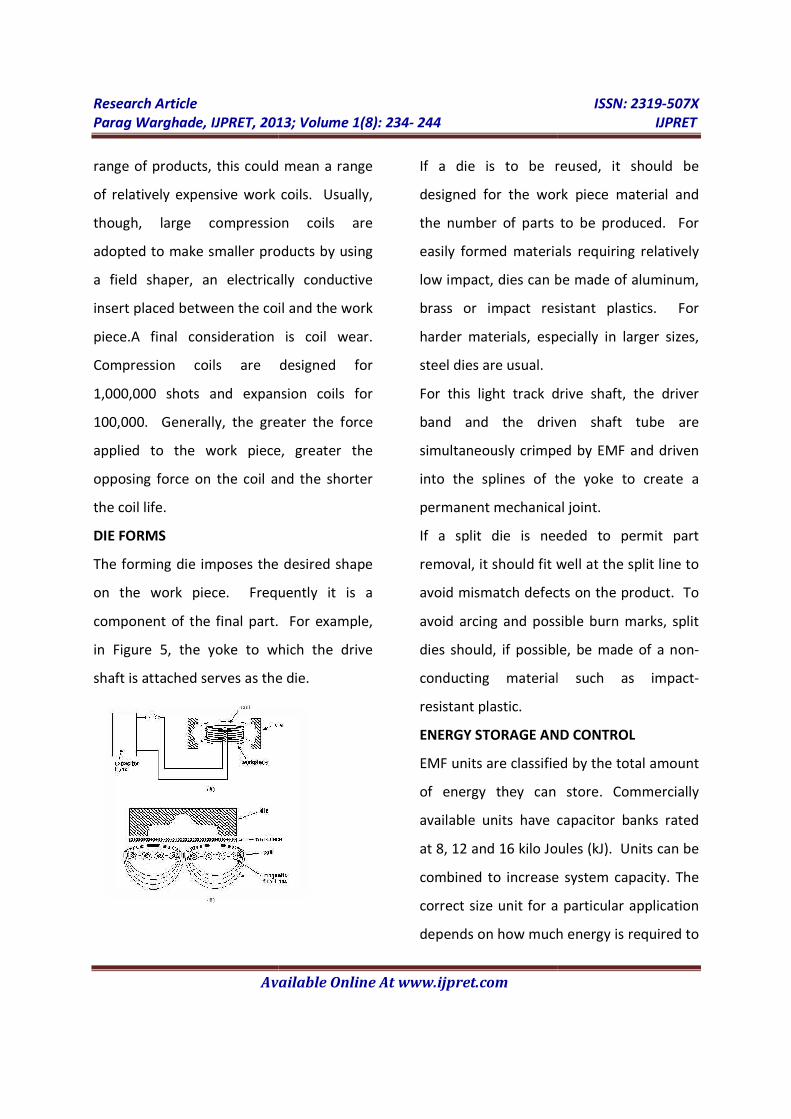
DIE FORMS
The forming die imposes the desired shape
on the work piece. Frequently it is a
component of the final part. For example,
in Figure 5, the yoke to which the drive
shaft is attached serves as the die.
Research Article
, IJPRET, 2013; Volume 1(8): 234- 244
Available Online At www.ijpret.com
range of products, this could mean a range
of relatively expensive work coils. Usually,
though, large compression coils are
adopted to make smaller products by using
a field shaper, an electrically conductive
insert placed between the coil and the work
piece.A final consideration is coil wear.
Compression coils are designed for
1,000,000 shots and expansion coils for
100,000. Generally, the greater the force
applied to the work piece, greater the
opposing force on the coil and the shorter
The forming die imposes the desired shape
on the work piece. Frequently it is a
component of the final part. For example,
in Figure 5, the yoke to which the drive
shaft is attached serves as the die.
If a die is to be reused, it should be
designed for the work piece material and
the number of parts to be produced. For
easily formed materials requiring relatively
low impact, dies can be made of aluminum,
brass or impact resistant plastics. For
harder materials, especially in larger sizes,
steel dies are usual.
For this light track drive shaft, the driver
band and the driven shaft tube are
simultaneously crimped by EMF and driven
into the splines of the yoke to create a
permanent mechanical joint.
If a split die is needed to permit part
removal, it should fit well at the split line to
avoid mismatch defects on the product. To
avoid arcing and possible burn marks, split
dies should, if possible, be made of a non
conducting material such as impact
resistant plastic.
ENERGY STORAGE AND CONTROL
EMF units are classified by the total amount
of energy they can store. Commercially
available units have capacitor banks rated
at 8, 12 and 16 kilo Joules (kJ). Units can be
combined to increase system capacity. The
correct size unit for a particular appli
depends on how much energy is required to
ISSN: 2319-507X
IJPRET
If a die is to be reused, it should be
esigned for the work piece material and
the number of parts to be produced. For
easily formed materials requiring relatively
low impact, dies can be made of aluminum,
brass or impact resistant plastics. For
harder materials, especially in larger sizes,
For this light track drive shaft, the driver
band and the driven shaft tube are
simultaneously crimped by EMF and driven
into the splines of the yoke to create a
permanent mechanical joint.
If a split die is needed to permit part
al, it should fit well at the split line to
avoid mismatch defects on the product. To
avoid arcing and possible burn marks, split
dies should, if possible, be made of a non-
conducting material such as impact-
ENERGY STORAGE AND CONTROL
MF units are classified by the total amount
of energy they can store. Commercially
available units have capacitor banks rated
at 8, 12 and 16 kilo Joules (kJ). Units can be
combined to increase system capacity. The
correct size unit for a particular application
depends on how much energy is required to
Research Article ISSN: 2319-507X
Parag Warghade, IJPRET, 2013; Volume 1(8): 234- 244 IJPRET
Available Online At www.ijpret.com
form each part, the rate at which magnetic
pulses are applied (production rate), and
how fast the coil and other electronic
components can dissipate heat.
To maintain close tolerance and consistent
product shape, the electromagnetic pulses
must be carefully controlled. Pulse must be
carefully controlled. Pulse magnitude
depends on the amount of energy released
from the capacitor bank. The voltage
charging the capacitors is carefully
measured and is turned off as soon as a
present level is reached. The timing of the
electromagnetic pulses is also carefully
controlled to ensure maximum production
rates. Rates of 200-600 parts/hour with
manual loading, and up to 12,000
parts/hour with automatic loading, are
possible.
EMF equipment operates at high voltage
and current, so appropriate caution is
needed to avoid accidents. Points at
different potentials, such the coil and the
work piece, must be adequately insulated
to prevent shorting and the insulation
checked frequently for signs of wear. All
coils fail eventually, usually as a result of
insulation breakdown. Since failure may be
accompanied by flying debris, a safety
shield is used between personnel and the
work coil.
ECONOMICAL CONSIDERATIONS
In deciding whether an EMF installation is
economically feasible, both startup and
operating cost have to be considered.
STARTUP COST
Start up costs include capital equipment
and training expenses. Equipment cost is
determined mostly by energy storage
capacity. An 8kJ unit, the smallest available,
cost around $35,000. A 16kJ unit, the size
most frequently used, cost $60,000-65,000.
EMF does not require particularly skilled
operators hence training costs are not high.
OPERATING COST
These include new coils ($4000-8000) or
field shapers ($1000-5000) for different
products, dies or drivers if these are
necessary, and electric power. EMF
equipment places no special demands on
the power supply.
Energy consumption is 1kWs per kJ
capacity. Therefore, assuming 1kwh cost
Rs. 6-00, the cost per form (second) in a
16kj system is (16x6)/3600 or Rs 0.026.
ADVANTAGES
Research Article ISSN: 2319-507X
Parag Warghade, IJPRET, 2013; Volume 1(8): 234- 244 IJPRET
Available Online At www.ijpret.com
Compared with other competing
technologies EMF is:
• Easy to use. The process is easy to
implement and requires no special
operator skill.
• Non-contact. There is generally no need
for lubricants, and usually no surface
marring, so cleaning and post finishing
are rarely necessary.
• Fast. Energy release to the work coil
takes only microseconds and capacitors
recharge in a few seconds.
• Repeatable. All process variables can be
precisely controlled.
• Amenable to automation. High
production rates are possible.
• Clean room compatible. Parts made in
an ultra clean or sterile environment
can be sealed in a plastic bag and
formed through the bag.
• Cost effective. The whole process is
performed in one step rather than the
two or three typical of competing
techniques.
• Joins metals to other metals or
nonmetals. Since only one component
needs to be conductive, metals also can
be jointed to rubber, glass, ceramics,
plastics and fiberglass.
• Save dies. In assembling, the “die” is
often an integral part of the product.
Other parts may required only half of a
matched-die set—the electromagnetic
force forms the other half.
• Causes minimal tool wear. Only the
coils need to be replaced occasionally.
• Forms most parts cold. Product
handling is simplified.
LIMITATIONS
• Work piece must be electrically
conductive, and, preferably, have a low
electrical resistivity (high conductivity).
• Process works best with thinner
materials.
• Minimum internal diameter of the tube
should be about 50mm for expansion
applications.
• Work coils are relatively expensive.
• High-resistance work pieces usually
require drivers, which can be used only
one and may have to be removed.
• Number of equipment suppliers is
limited.
Research Article ISSN: 2319-507X
Parag Warghade, IJPRET, 2013; Volume 1(8): 234- 244 IJPRET
Available Online At www.ijpret.com
APPLICATIONS
EMF is widely used in Automotive,
aerospace, appliance, ordnance, electrical
and nuclear industries for:
• Fastening clamping rings over rubber
sleeves on shock absorbers
• Attaching reinforcing bands on oil filters
• Assembling aluminum gas tank, filler
tubes and plastic gas cap holders.
• Clamping steel covers on aluminum
automobile fuel pumps
• Attaching aluminum drive shafts to
yokes.
• Assembling coaxial-cable termination
joints.
• Assembling lighter-fluid nozzles and
wicks
• Attaching flanges to tubing
• Forming contoured tubing parts for
ductile intersections.
• Correcting surface deformations on
aircraft skins.
• Riveting aircraft wing spars.
• Welding end closures on nuclear reactor
fuel rod.
Some of the Manufacturing problems
successfully solved with EMF include:
• On Blower wheels, the louvers that
move the air must be tightly fastened to
three discs mounted on a shaft. Possible
fastening method includes fastening
each lover simultaneously by
electromagnetic forming. EMF was
chosen because it was least expensive,
fastest and produced the most
satisfactory product.
• Nuclear fuel elements and closures
were made by tungsten-inert-gas
welding. Such welds were difficult to
make, difficult to inspect and unreliable.
By changing to EM pulse welding, the
manufacturer obtained more
consistent, metallurgically-bonded
joints at a lower cost. The time to
manufacture and inspect each fuel
element was reduced from 40 to 8
hours.
COMPETING TECHNOLOGIES
In compression applications, the main
competing technologies are conventional
swaging, rotary roll forming and multiple-
jaw shrinking. Multiple-piece steel mandrels
and steel roller bearing tools are
traditionally used in expansion applications.

Research Article ISSN: 2319-507X
Parag Warghade, IJPRET, 2013; Volume 1(8): 234- 244 IJPRET
Available Online At www.ijpret.com
Standard joining methods include welding,
brazing, bolting and pinning. Most of these
methods include welding, brazing, bolting
and pinning. Most of these methods
require two or three separate steps, and all
involve direct mechanical contact between
the tool and the work piece, resulting in
surface flaws that may have to be removed
in a later finishing process. EMF is a one-
step, non-contact process, so surface
finishing is not a problem: Furthermore,
the magnetic field passes through non
conducting materials so parts can be
formed after anodizing or application of
other surface finishes, or after they have
been sealed in plastic bags in a clean room.
Although research is underway to improve
the process, EMF does not yet easily handle
thick-walled, high strength materials. For
these applications, contact methods are
more cost effective.
CONCLUSION
• Excellent technique for forming thin
metals.
• Good for mechanically joining metals or
non-metals.
• Its quicker, easier, and easy to
implement.
• Easily automated and product formed is
free from any defects.
• Likely rapid growth of EMF machines.
REFRENCES
1. MANUFACTURING TECHNOLOGY
TODAY(NICMAP Publication),Volume-6,
Issue-1, January 2007
2. M. Padmanabhan, M.S., 1997,
"Wrinkling and Springback in
Electromagnetic Sheet Metal Forming and
Ring Compression".
3. Wen-Fu Pon, Ph.D., 1997,"A Model for
Electromagnetic Ring Expansion and Its
Application to Material Characterization ".
4. M. Plum, "Electromagnetic Forming",
Metals Handbook, volume 14, 9th edition,
ASM, 645, (1995).
5. V. S. Balanethiram, Ph.D., 1996,
"Hyperplasticity : Enhanced Formability of
Sheet Metals at High Workpiece Velocity".
6. Wikipedia