INTERNATIONAL JOURNAL OF ADVANCED PRODUCTION AND ...
8
Available online at www.ijapie.org INTERNATIONAL JOURNAL OF ADVANCED PRODUCTION AND INDUSTRIAL ENGINEERING IJAPIE-2020-01-146, Vol 5 (1), 49-56 https://doi.org/10.35121/ijapie202001146 IJAPIE Connecting Science & Technology with Management. A Journal for all Products & Processes. | IJAPIE | ISSN: 2455–8419 | www.ijapie.org | Vol. 5 | Issue. 1 | 2020 | 49 | Microstructural and Fracture Surface Study of Friction Stir Welded AA5082- AA7075 Butt Joints Gaurav Kumar 1, *, Rajeev Kumar 1 and Ratnesh Kumar 1 1 Birla Institute of Technology, Mesra, Jharkhand, India-835215 *Email: [email protected] ABSTRACT: In this study, experiments were performed to analyse the fracture surface and microstructural behaviour of friction stir welded (FSW) AA5082-AA7075butt joints. Three samples at varying speed and constant feed were prepared to identify optimum tool speed to produce FSW AA5082-AA7075 butt joints having maximum tensile strength and fatigue life. A scanning electron microscope (SEM) was used to analyse microstructure and fracture surfaces. The samples prepared exhibited a considerable difference in their fatigue life and tensile strength. Microstructural analysis showed the refinement of grains present in the stir zone (SZ), also known as the weld nugget, and thermo-mechanically affected zone (TMAZ). The study of the fracture surface showed that the mode of failure was ductile in nature Keywords: Friction Stir Welding, Solid state welding, Dissimilar Al welding, Microstructure, Fracture. INTRODUCTION In today’s scenario, the automobile and aerospace industries is moving towards the usage material with high strength to weight ratio. Due to this, the manufacturers have shifted their focus from steel to aluminium. Aluminium has a better strength to weight ratio than steel. But aluminium is very difficult to weld. The few processes used for welding aluminium, viz. resistance spot welding, tungsten inert gas welding, gas metal arc welding, etc., produce welds of poor quality. To overcome this problem, Mr Wayne Thomas [1]of The Welding Institute (TWI) in Cambridge, UK developed friction stir welding (FSW) in year 1991. InFSW, the materials are joined below their melting point making ita solid state joining process. As the process happens below the melting point of the material, there is no observable change in the properties of the weld from the base material. In FSW, a cylindrical tool which comprisesof a shoulder and apin is rotated and plunged into the joint line of the materials that are to be joined[5]. As the tool shoulder comes in contact with the material, it generates enough heat for the materialto reach its plastic region, and then the tool is traversed along the joint line. As the tool traverses along the joint line, the pin collects material from its front and throws it towards its back forging a solid state joint[6]. It is important to maintain the contact between the tool shoulder and the material as it is a critical criteria for the forging action happening behind the tool. For the constant shoulder-material contact, sufficient down force is applied and maintained throughout[7][8]. FSW has appealedtonumerous industrial sectors, such as, transportation, aeronautics and automotiveas it has much industrial potential and many other advantages[2]. The most substantial advantage being its ability to weld alloys that are impossible or challenging to join using the fusion welding techniques. The FSW is a solid state process and hence, re-solidification and the associated problems, such as, second phase formation, brittleness, porosity and cracking, does not happen[3]. As FSW occurs at a lower temperature, it allows joining of the material with lower residual stress and lower distortion. FSW does not require shielding gases or filler material
Transcript of INTERNATIONAL JOURNAL OF ADVANCED PRODUCTION AND ...

Available online at www.ijapie.org
INTERNATIONAL JOURNAL OF ADVANCED PRODUCTION AND INDUSTRIAL ENGINEERING
IJAPIE-2020-01-146, Vol 5 (1), 49-56
https://doi.org/10.35121/ijapie202001146
IJAPIE Connecting
Science & Technology with Management.
A Journal for all Products & Processes.
| IJAPIE | ISSN: 2455–8419 | www.ijapie.org | Vol. 5 | Issue. 1 | 2020 | 49 |
Microstructural and Fracture Surface Study of Friction Stir Welded AA5082-AA7075 Butt Joints
Gaurav Kumar1,*, Rajeev Kumar1 and Ratnesh Kumar1
1Birla Institute of Technology, Mesra, Jharkhand, India-835215
*Email: [email protected]
ABSTRACT: In this study, experiments were performed to analyse the fracture surface and microstructural behaviour of friction stir welded (FSW) AA5082-AA7075butt joints. Three samples at varying speed and constant feed were prepared to identify optimum tool speed to produce FSW AA5082-AA7075 butt joints having maximum tensile strength and fatigue life. A scanning electron microscope (SEM) was used to analyse microstructure and fracture surfaces. The samples prepared exhibited a considerable difference in their fatigue life and tensile strength. Microstructural analysis showed the refinement of grains present in the stir zone (SZ), also known as the weld nugget, and thermo-mechanically affected zone (TMAZ). The study of the fracture surface showed that the mode of failure was ductile in nature
Keywords: Friction Stir Welding, Solid state welding, Dissimilar Al welding, Microstructure, Fracture.
INTRODUCTION
In today’s scenario, the automobile and aerospace industries is moving towards the usage material with high strength to weight ratio. Due to this, the manufacturers have shifted their focus from steel to aluminium. Aluminium has a better strength to weight ratio than steel. But aluminium is very difficult to weld. The few processes used for welding aluminium, viz. resistance spot welding, tungsten inert gas welding, gas metal arc welding, etc., produce welds of poor quality. To overcome this problem, Mr Wayne Thomas [1]of The Welding Institute (TWI) in Cambridge, UK developed friction stir welding (FSW) in year 1991. InFSW, the materials are joined below their melting point making ita solid state joining process. As the process happens below the melting point of the material, there is no observable change in the properties of the weld from the base material. In FSW, a cylindrical tool which comprisesof a shoulder and apin is rotated and plunged into the joint line of the materials that are to be joined[5]. As the tool shoulder comes in contact with the material, it generates enough heat for the materialto reach its plastic region, and then the tool is traversed along the joint line. As the tool traverses along the joint line, the pin collects material from its front and throws it towards its back forging a solid state joint[6]. It is important to maintain the contact between the tool shoulder and the material as it is a critical criteria for the forging action happening behind the tool. For the constant shoulder-material contact, sufficient down force is applied and maintained throughout[7][8].
FSW has appealedtonumerous industrial sectors, such as, transportation, aeronautics and automotiveas it has much industrial potential and many other advantages[2]. The most substantial advantage being its ability to weld alloys that are impossible or challenging to join using the fusion welding techniques. The FSW is a solid state process and hence, re-solidification and the associated problems, such as, second phase formation, brittleness, porosity and cracking, does not happen[3]. As FSW occurs at a lower temperature, it allows joining of the material with lower residual stress and lower distortion. FSW does not require shielding gases or filler material

Gaurav Kumar et al., International Journal of Advanced Production and Industrial Engineering
| IJAPIE | ISSN: 2455–8419 | www.ijapie.org | Vol. 5 | Issue. 1 | 2020 | 50 |
making it an energy efficient process. FSW, also, does not generate spatter, arc flash,fumes and pollution which makes it better in comparison to fusion welding techniques[4].
II MATERIALS AND METHODS
The Al alloys, AA5082 and AA7075, used for the study were 6mm thick sheets. These materials have similarities in their areas of application. Both AA5082 and AA7075 can be used for general purposes. However, the main reason that they are used for general purpose is their cost. Accordingly, AA5082 is mainly used in the field of marine and shipbuilding industries. The high cost of AA7075 limits its application to aircraft and aerospace industries[9].Dissimilar FSW butt joints of AA5082-AA7075 were produced under varying tool speed at constant feed, as shown in Table 1. High strength steel (HSS) was used to produce FSW tool. The tool had three parts: shank, shoulder, and pin. The tool has a cylindrical shank of diameter 15.18 mm and a shoulder of 17.97 mm diameter. The pin was tapered with6.1 mm base diameter and 4.15 mm top diameter as shown in Fig. 1.The HAAS VF-1CNC milling machine was used to produce the FSW welds. Tables 1 and 2 discuss the parameters used for producingthe welds. Figure 2 shows the setup for FSW.
Table 1: Varying speed at constant feed for FSW
Sample No.
Speed (RPM) Feed (mm/min)
1 500 20
2 700 20
3 900 20
Table 2: Various Parameter for FSW
FSW Control Parameters
Rotation Direction Counter Clock Wise (CCW)
Advancing Side AA7075
Retreating Side AA5082
Fig. 1: FSW Tool

Gaurav Kumar et al., International Journal of Advanced Production and Industrial Engineering
| IJAPIE | ISSN: 2455–8419 | www.ijapie.org | Vol. 5 | Issue. 1 | 2020 | 51 |
III EXPERIMENTS
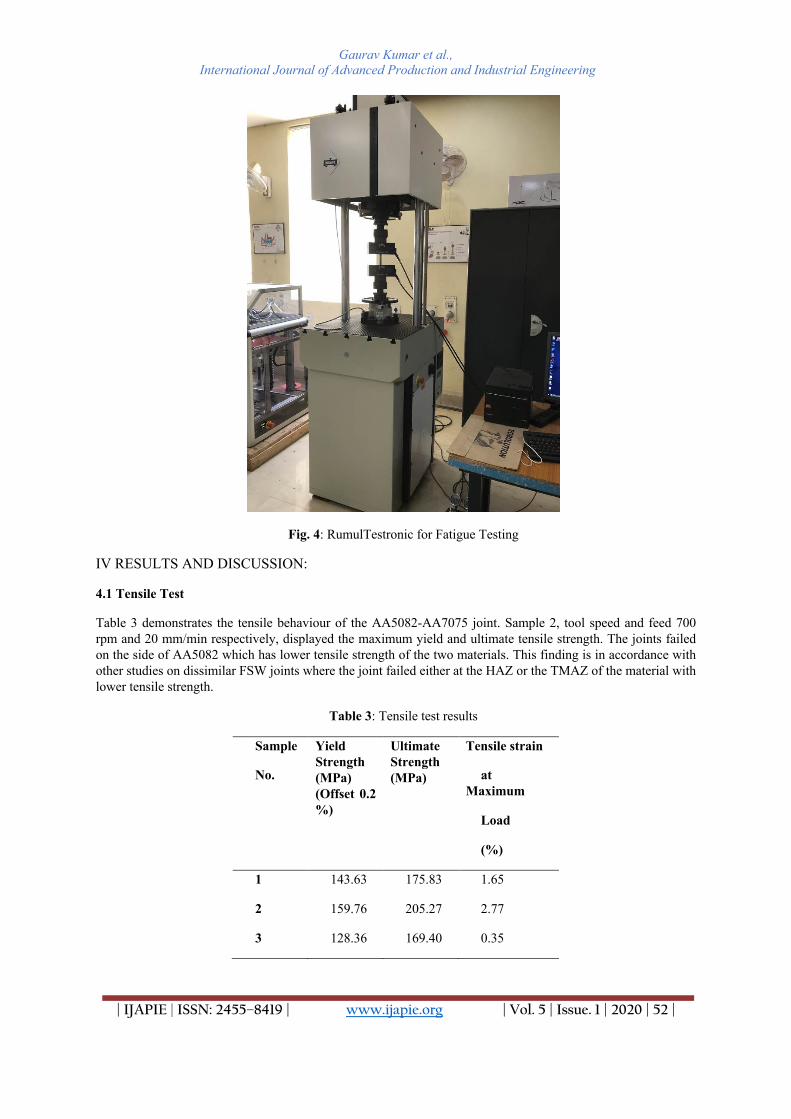
The test samples for fatigue and tensile tests were prepared and are shown in Fig. 3. Subsequently, the tensile test was performed on Instron® 8801 which is a servo-hydraulic testing system having a 100 kN load cell. The strain rate was set to 5 mm/min. For fatigue testings, RUMUL TESTRONIC (Fig. 4) was used fully reversed load condition, i.e. R=-1. The failure of the test sample was defined as the criterion for stopping the fatigue test. Fractured surface of the failed samples were studied using SEM techniques. For studying the microstructure, samples of size 30 mm × 2 mm × 6mm were cut and polished in STRUERS Labpool-5 polishing machine. Subsequently, the sample was etched using Keller’s reagent (HNO3, HCl, HFl and distilled water). Finally the sample studied under JEOL JSM-6390LV scanning electron microscope.
Fig. 2: FSW Setup for production of AA5082-AA7075 butt joints
Fig. 3: AA5082-AA7075 butt welds prepared at different speeds
Gaurav Kumar et al., International Journal of Advanced Production and Industrial Engineering
| IJAPIE | ISSN: 2455–8419 | www.ijapie.org | Vol. 5 | Issue. 1 | 2020 | 52 |
Fig. 4: RumulTestronic for Fatigue Testing
IV RESULTS AND DISCUSSION:
4.1 Tensile Test
Table 3 demonstrates the tensile behaviour of the AA5082-AA7075 joint. Sample 2, tool speed and feed 700 rpm and 20 mm/min respectively, displayed the maximum yield and ultimate tensile strength. The joints failed on the side of AA5082 which has lower tensile strength of the two materials. This finding is in accordance with other studies on dissimilar FSW joints where the joint failed either at the HAZ or the TMAZ of the material with lower tensile strength.
Table 3: Tensile test results
Sample
No.
Yield Strength (MPa) (Offset 0.2 %)
Ultimate Strength (MPa)
Tensile strain
at Maximum
Load
(%)
1 143.63 175.83 1.65
2 159.76 205.27 2.77
3 128.36 169.40 0.35

Gaurav Kumar et al., International Journal of Advanced Production and Industrial Engineering
| IJAPIE | ISSN: 2455–8419 | www.ijapie.org | Vol. 5 | Issue. 1 | 2020 | 53 |
4.2 Fatigue Test
Figure 5 shows the results of the fatigue tests performed at 20 MPa, 35MPa and 50 MPa stress. The results demonstrate that Sample 2 (tool speed = 700 rpm and feed = 20 mm/min) has higher fatigue life at any given stress than the other samples tested. This result is in accordance with tensile test results where Sample 2 had the highest tensile strength.
Fig. 5: Fatigue test results
4.3 Microstructural Analysis
The microstructure of FSW AA5082-AA7075 of Sample 2, i.e. at a tool rotation speed of 900 RPM and feed of 40 mm/minis shown in Fig. 6. The material on left of the centre of the weld is AA5082 (RS) and on the right is AA7075(AS).The effect of etching on the surface of the sample was different for both the materials which displayed two distinct colours.The three zones of FSW can easily be distinguished, the zones being the SZ, TMAZ and HAZ. After examining the microstructure, it can be seen that the grain structure is different in each zone as FSW led to the restructuring of the grains in these zones. This restructuring of the grain after FSW is witnessed in numerous aluminium alloys. Further, it is observed that the grain size in all the regions is different and the SZ has the smallest grain size. The grain size increases in every successive zone. The refinement of the grains is a result of stirring action performed by the tool pin.This stirring action leads to the simultaneous action of frictionalheating and plastic deformation during the welding process which results in dynamic recrystallization of the material and hence restructuring and refinement of the grains[10][11].

Gaurav Kumar et al., International Journal of Advanced Production and Industrial Engineering
| IJAPIE | ISSN: 2455–8419 | www.ijapie.org | Vol. 5 | Issue. 1 | 2020 | 54 |
Fig. 6: Microstructure of different areas of FSW AA5082-AA7075 butt weld (a) Base material (AA7075) (b) HAZ (AA7075) (c) TMAZ (AA7075) (d) SZ (AA7075) (e) Base material (AA5082) (f) HAZ (AA5082) (g) TMAZ (AA5082) (h) SZ (AA5082)
4.4 Fracture Analysis
For the fracture study, the central and bottom zones of the weld were considered and the upper zone of the weld was neglected as the difference in the fracture morphology can be observed only in the central and the bottom zones due to lack of penetration of the tool pin. However, no considerable difference was apparent in these zones which suggests that tool pin had good penetration. The fracture surface of Sample 2 was studied. The fracture surface was observed and the point of crack initiation was recognised. The fatigue crack growth does not depend upon material properties as it is greatly confined to the normal stress plane. At high stress intensity, crack growth leaves a mark during each load cycle.This creates a band of markings along the fracture surface and these markings are referred to as striation[12][13]. Striations help to determine the direction of crack growth.The centre of the striations was identified which helped in recognising the point of crack initiation and the area around it is shown in Fig. 7(a).Fig. 7(b) shows a magnified view of the area highlighted in Fig.7(a). The areas A, B and C shows the presence of striations which is evident due to the formation of ridge like structures during fatigue loading. The presence of these striationsin the fracture surface show that the failure was ductile innature.

Gaurav Kumar et al., International Journal of Advanced Production and Industrial Engineering
| IJAPIE | ISSN: 2455–8419 | www.ijapie.org | Vol. 5 | Issue. 1 | 2020 | 55 |
Fig. 7: (a) Fracture surface of FSW Sample 2 as seen under SEM (b) Magnified view of the highlighted region A (c) Magnified view of the region B showing striations (d) Magnified view of the region C
V CONCLUSIONS
Fracture surface and the microstructural behaviour of dissimilar AA5082-AA7075 butt FSW joints produced at varying tool speed and feed were studied. No post-welding treatments, such as surface finish or heat treatment, were carried out on the samples. The following conclusions are presented:
• The microstructural analysis illustrated the restructuring and refinement of grains due to the dynamic recrystallization of the material. This was evident by the smaller grain size of the weld zone, specifically in the SZ, than the base material. • The tensile and the fatigue test showed that Sample 2, prepared at a tool rotational speed of
700 rpm, has the maximum ultimate tensile strength, yield strength, tensile strain at maximum load and also the maximum fatigue life. Also, the results demonstrate that for tool speed, the ultimate strength increases with increasing tool speed to a maximum and then it decreases. • The study of fracture surface demonstrated that the welded regions were ductile in nature.
This was established by the presence of striations samples.
From the studies made it can be established that Sample 2 was the best specimen as it exhibited the best fatigue life and the tensile strength. Moreover, there were no surface defects or pores found in Sample 2 which makes it more reliable in real-world conditions.Sample 2 was prepared at a tool rotational speed of 700 RPM and canbe considered as optimal tool rotational speed for preparing AA5082-AA7075 FSW butt welds at a feed of 20 mm/min.

Gaurav Kumar et al., International Journal of Advanced Production and Industrial Engineering
| IJAPIE | ISSN: 2455–8419 | www.ijapie.org | Vol. 5 | Issue. 1 | 2020 | 56 |
References
[1] W. M. Thomas, E. D. Nicholas, J. C. Needham, M. G. Murch, P. Temple-Smith, and C. J. Dawes, “Friction Stir Butt Welding, International Patent Appl. n. PCT/GB92/02203 and GB Patent Appl. n. 9125978.8,” US Pat., no. 5,460,317, 1991.
[2] A. J. Barnes, H. Raman, A. Lowerson, and D. Edwards, “Recent Application of Superformed 5083 Aluminum Alloy in the Aerospace Industry,” Mater. Sci. Forum, vol. 735, pp. 361–371, 2013.
[3] A. S. Sedmak et al., “Heat input effect of friction stir welding on aluminum alloy AA 6061-T6 welded joint,” Therm. Sci., vol. 20, no. 2, pp. 637–641, 2016.
[4] J. Zhao, F. Jiang, H. Jian, K. Wen, L. Jiang, and X. Chen, “Comparative investigation of tungsten inert gas and friction stir welding characteristics of Al-Mg-Sc alloy plates,” Mater. Des., vol. 31, no. 1, pp. 306–311, 2010.
[5] R. Nandan, T. DebRoy, and H. K. D. H. Bhadeshia, “Recent advances in friction-stir welding - Process, weldment structure and properties,” Prog. Mater. Sci., vol. 53, no. 6, pp. 980–1023, 2008.
[6] V. Infante, D. F. O. Braga, F. Duarte, P. M. G. Moreira, M. De Freitas, and P. M. S. T. De Castro, “Study of the fatigue behaviour of dissimilar aluminium joints produced by friction stir welding,” Int. J. Fatigue, vol. 82, pp. 310–316, 2016.
[7] H. M. Rao et al., “Fatigue and fracture of friction stir linear welded dissimilar aluminum-to-magnesium alloys,” Int. J. Fatigue, vol. 82, pp. 737–747, 2016.
[8] L. Ceschini, I. Boromei, G. Minak, A. Morri, and F. Tarterini, “Effect of friction stir welding on microstructure, tensile and fatigue properties of the AA7005/10 vol.%Al2O3p composite,” Compos. Sci. Technol., vol. 67, no. 3–4, pp. 605–615, 2007.
[9] C. G. Rhodes, M. W. Mahoney, W. H. Bingel, R. A. Spurling, and C. C. Bampton, “Effects of friction stir welding on microstructure of 7075 aluminum,” Scr. Mater., vol. 36, no. 1, pp. 69–75, 1997.
[10] R. John, K. V. Jata, and K. Sadananda, “Residual stress effects on near-threshold fatigue crack growth in friction stir welds in aerospace alloys,” Int. J. Fatigue, vol. 25, no. 9–11, pp. 939–948, 2003.
[11] J. Q. Su, T. W. Nelson, R. Mishra, and M. Mahoney, “Microstructural investigation of friction stir welded 7050-T651 aluminium,” Acta Mater., vol. 51, no. 3, pp. 713–729, 2003.
[12] R. J. Parrington, “Fractography of metals and plastics,” Pract. Fail. Anal., vol. 2, no. 5, pp. 16–19, 2002. [13] S.-W. Song, B.-C. Kim, T.-J. Yoon, N.-K. Kim, I.-B. Kim, and C.-Y. Kang, “Effect of welding parameters on
weld formation and mechanical properties in dissimilar Al alloy joints by FSW,” Mater. Trans., vol. 51, no. 7, pp. 1319–1325, 2010.