Internal Langmuir Probe Mapping of a Hall Thruster with
18
American Institute of Aeronautics and Astronautics 1 Internal Langmuir Probe Mapping of a Hall Thruster with Xenon and Krypton Propellant Jesse A. Linnell * and Alec D. Gallimore † Plasmadynamics and Electric Propulsion Laboratory, Department of Aerospace Engineering, University of Michigan, Ann Arbor, MI 48109 USA A cylindrical Langmuir probe is used with the Plasmadynamics and Electric Propulsion Laboratory High-speed Axial Reciprocating Probe system to map the plasma properties internal to the NASA-173Mv1 Hall thruster using xenon and krypton propellant. Measurements are taken for xenon at an anode flow rate of 10 mg/s and discharge voltages of 300 V and 500 V. Two 500-V krypton points are also presented below; one that matches discharge current and one that matches the magnetic field topology of the 500-V xenon case. These data yield information that aid in the fundamental understanding of discharge channel physics with xenon and krypton propellant. The measured plasma properties include ion number density and electron temperature. For the xenon points, the maximum electron temperatures reach 40 and 50 eV for the 300 and 500-V cases, respectively. Due to lower ionization losses, the krypton points have slightly higher maximum electron temperature of 60 eV. The maximum ion number densities are approximately 3×10 12 and 4×10 12 cm -3 for xenon and krypton, respectively. With these data, the approximate location of the ionization zone is determined. Xenon ionization zone is found to be strongly connected to the Hall current region, whereas the krypton ionization zone is located upstream of the Hall current. The plasma lens topology is shown to focus the ions toward the center of the discharge channel and the magnetic mirror is shown to aid in propellant ionization. With these measured properties in combination with previous emissive probe measurements, it is also possible to calculate the location and magnitude of the Hall current. When krypton is operated with the same magnetic field topology as xenon, the locations of the acceleration zone, Hall current location, and beam focusing are found to resemble the xenon case. Investigation of discharge current perturbations yields useful information in determining the location of the Hall current and acceleration zone, and helps further our understanding of interaction between the plasma and probe. Nomenclature A p = Probe surface area A s = Probe collection area B = Magnetic field E = Electric Field e = Elementary charge f B = Breathing mode frequency I i = Ion current J E×B = E×B drift current k B = Boltzmann’s constant K n = Knudsen number L i = Ionization zone length l p = Probe length m e = Electron mass * Ph.D. Candidate, Aerospace Engineering, [email protected], 1919 Green Rd Room B107, Member AIAA † Arthur F. Thurnau Professor of Aerospace Engineering and of Applied Physics, Associate Dean for Academic Programs and Initiatives, Aerospace Engineering, [email protected], 1919 Green Rd Room B107, Associate Fellow AIAA. 42 nd AIAA/ASME/SAE/ASEE Joint Propulsion Conference and Exhibit AIAA-2006-4470 9-12 July 2006, Sacramento, California
Transcript of Internal Langmuir Probe Mapping of a Hall Thruster with
American Institute of Aeronautics and Astronautics
1
Internal Langmuir Probe Mapping of a Hall Thruster with Xenon and Krypton Propellant
Jesse A. Linnell* and Alec D. Gallimore† Plasmadynamics and Electric Propulsion Laboratory, Department of Aerospace Engineering, University of
Michigan, Ann Arbor, MI 48109 USA
A cylindrical Langmuir probe is used with the Plasmadynamics and Electric Propulsion Laboratory High-speed Axial Reciprocating Probe system to map the plasma properties internal to the NASA-173Mv1 Hall thruster using xenon and krypton propellant. Measurements are taken for xenon at an anode flow rate of 10 mg/s and discharge voltages of 300 V and 500 V. Two 500-V krypton points are also presented below; one that matches discharge current and one that matches the magnetic field topology of the 500-V xenon case. These data yield information that aid in the fundamental understanding of discharge channel physics with xenon and krypton propellant. The measured plasma properties include ion number density and electron temperature. For the xenon points, the maximum electron temperatures reach 40 and 50 eV for the 300 and 500-V cases, respectively. Due to lower ionization losses, the krypton points have slightly higher maximum electron temperature of 60 eV. The maximum ion number densities are approximately 3×10¹² and 4×1012 cm-3 for xenon and krypton, respectively. With these data, the approximate location of the ionization zone is determined. Xenon ionization zone is found to be strongly connected to the Hall current region, whereas the krypton ionization zone is located upstream of the Hall current. The plasma lens topology is shown to focus the ions toward the center of the discharge channel and the magnetic mirror is shown to aid in propellant ionization. With these measured properties in combination with previous emissive probe measurements, it is also possible to calculate the location and magnitude of the Hall current. When krypton is operated with the same magnetic field topology as xenon, the locations of the acceleration zone, Hall current location, and beam focusing are found to resemble the xenon case. Investigation of discharge current perturbations yields useful information in determining the location of the Hall current and acceleration zone, and helps further our understanding of interaction between the plasma and probe.
Nomenclature Ap = Probe surface area As = Probe collection area B = Magnetic field E = Electric Field e = Elementary charge fB = Breathing mode frequency Ii = Ion current JE×B = E×B drift current kB = Boltzmann’s constant Kn = Knudsen number Li = Ionization zone length lp = Probe length me = Electron mass
* Ph.D. Candidate, Aerospace Engineering, [email protected], 1919 Green Rd Room B107, Member AIAA † Arthur F. Thurnau Professor of Aerospace Engineering and of Applied Physics, Associate Dean for Academic Programs and Initiatives, Aerospace Engineering, [email protected], 1919 Green Rd Room B107, Associate Fellow AIAA.
42nd AIAA/ASME/SAE/ASEE Joint Propulsion Conference and Exhibit AIAA-2006-4470 9-12 July 2006, Sacramento, California
American Institute of Aeronautics and Astronautics
2
Mi = Ion mass ne = Electron number density ni = Ion number density po = Containment vessel pressure rp = Probe radius Te = Electron temperature V = Voltage Vi = Ion velocity Vn = Neutral velocity δ = Sheath thickness λD = Debye length λMFP = Ion mean free path τl = End effect parameter
I. Introduction all thrusters are space propulsion devices that use crossed electric and magnetic fields to ionize and accelerate propellant atoms to high exhaust velocities. Electron mobility is impeded by a large applied magnetic field,
which results in the creation of a self-consistent electric field. The crossed electric and magnetic fields cause the electrons to follow a closed drift path, and for this reason Hall thrusters are often referred to as closed-drift thrusters. Generally, noble gases of high atomic weight are used as propellant.
Of the noble gases, xenon has historically been the preferred propellant because of its high molecular weight and low ionization potential. The use of a lighter propellant increases ion velocities and therefore can increase specific impulse, which in turn extends Hall thrusters into a larger range of mission applications. However, the higher ionization potentials of the lighter noble gases result in an efficiency deficit that has precluded these propellants from any serious discussion as viable options for space application. Although previous studies report krypton to have an inferior performance as compared to xenon, results using the NASA-457M1 and the NASA-400M2 indicate that krypton can be operated at efficiencies comparable to xenon. In order to better understand and reduce the efficiency gap between xenon and krypton, it will be necessary to conduct a detailed study of krypton propellant in Hall thrusters including an investigation of the processes internal to the Hall thruster discharge channel.
In conjunction with a previous internal emissive probe investigation of krypton propellant,3 the internal mapping with a single Langmuir probe is conducted. A cylindrical Langmuir probe is mounted on the Plasmadynamics and Electric Propulsion Laboratory’s (PEPL) High-Speed Axial Reciprocating Probe (HARP) system and the internal plasma properties are measured. The measured properties include ion number density and electron temperature. A similar investigation on the UM/AFRL P5 Hall thruster has been conducted by Haas using a double Langmuir probe.4 A single Langmuir probe is used in this investigation to improve the accuracy of the electron temperature measurements by avoiding the artificial electron saturation seen in double probe I-V characteristics. In recent years there has been extensive work mapping of ion engine discharge chambers and near cathode region using a similar technique.5-10 With the combination of floating emissive probe measurement and Langmuir probe measurements, it is now possible to take a deeper look at internal plasma processes. Areas of investigation for this paper include quantifying the Hall current, analyzing discharge current perturbation trends, and approximating the location of the ionization zone.
II. Experimental Apparatus
A. Facility The measurements reported in this paper are conducted in the Large Vacuum Test Facility (LVTF) at the
University of Michigan’s Plasmadynamics and Electric Propulsion Laboratory. The LVTF is a cylindrical stainless-steel tank that is 9 m long and 6 m in diameter. The vacuum chamber is evacuated using 7 CVI model TM-1200 internal cryopumps. The pumps are capable of pumping 240,000 l/s of xenon and 252,000 l/s of krypton. The pressure is monitored by using two hot-cathode ionization gauges. The vacuum chamber operates at a base pressure of 1.7×10⁻⁷ torr and approximately 3.4×10⁻⁶ torr during both the krypton and xenon thruster operation points.
High-purity research grade xenon and krypton are used as propellants for the following measurements. The purity level of xenon and krypton are both 99.999%. The propellants are supplied through propellant feel lines using 20 and 200 sccm mass flow controllers for the cathode and anode, respectively. The mass flow controllers are calibrated using a constant volume method. The compressibility correction factor for xenon and krypton are
H

American Institute of Aeronautics and Astronautics
3
calculated using the Redlich-Kwong equation of state. Error in the mass flow controllers is approximately ±1% of full scale.
B. Experimental Setup As shown in Fig. 1, the NASA-173Mv1 is mounted on two linear (radial and axial) tables that control the probe
alignment and positioning. The Langmuir probe is mounted on the HARP system, which is securely fixed downstream of the thruster to dampen any vibrations caused by the high acceleration of the probe. These individual components are discussed in greater detail below.
C. Thruster The NASA-173Mv1 Hall thruster11 (Fig. 2) is used for all measurements.
In addition to the standard inner and outer magnetic coils, the NASA-173Mv1 uses a trim coil to shape the magnetic field topology. The thruster is run for one hour for initial conditioning and is warmed up for at least 30 minutes at a given operation point before data are collected.
The magnetic field created by the trim coil is found to improve thruster efficiency by establishing what is commonly referred to as a plasma lens. A plasma lens uses curved magnetic field lines to focus ions toward the center of the discharge channel.3,12 This phenomenon can be explained because to first order the magnetic field lines chart the equipotential lines inside a Hall thruster. Another feature of the magnetic field topology is the magnetic mirror effect, which pushes electrons away from the walls and toward the center of the discharge channel. The magnetic field topology has been shown to improve ion acceleration processes and internal electron dynamics.11,13
A Busek BHC-50-3UM hollow cathode is used for all measurements. The cathode flow rate is equal to 10% of the anode flow rate. The cathode axial centerline is mounted 30 degrees off horizontal and the center of the cathode orifice is placed 30 mm downstream and 30 mm above the thruster outer face.
D. High-Speed Axial Reciprocating Probe The HARP14,15 (Fig. 3) has a linear motor
assembly providing direct linear motion at very high speed and large acceleration. The linear motor is an LM210 manufactured by Trilogy that has a three-phase brushless DC servomotor consisting of a linear, “U”-shaped magnetic track and a “T”-shaped coil moving on a set of linear tracks. A linear encoder provides positioning resolution to 5 microns. The table is covered by a stainless steel
HARP
Single Langmuir Probe
NASA-173Mv1
Axial Table
Rad
ial
Tab
le
Figure 1. Internal Langmuir Probe Experimental Setup
Figure 2. NASA-173Mv1 Hall
Thruster
Figure 3. High-Speed Axial Reciprocating Probe System

American Institute of Aeronautics and Astronautics
4
and graphite shroud to protect the HARP from excessive heating and high-energy ions. One side has a thin slit running the length of the table through which a probe boom extends. The HARP is capable of moving small probes at speeds of 250 cm/s with linear accelerations of 7 g’s.
E. Langmuir Probe 1. Theory of Operation
Electrostatic probes are one of the most widely used diagnostics for determining plasma parameters. Due to the early work of Irving Langmuir, these electrostatic probes are often referred to as Langmuir probes.16,17 The single Langmuir probe consists of an electrode connected to an electrical circuit allowing variation of probe voltage with respect to the local plasma, and the collection of current at each corresponding voltage. The current and voltage measurements create a current-voltage (I-V) characteristic from which properties including plasma potential, floating potential, electron temperature, and plasma density can be extracted. Although simple in operation, interpretation of the I-V characteristics is greatly complicated by a host of effects.
Langmuir probe operation can be divided into different probe regimes based on the two non-dimensional parameters: the Knudsen number (Kn) and Debye length (λD). The Knudsen number (Kn=λMFP/rp) relates the ion mean free path (λMFP) to the probe radius (rp) and gives a relative measure of the number of ion collisions as compared to the length scale of the probe. The Knudsen number also determines if the probe is in the collisionless or continuum plasma regimes. Since the mean free path of ions and electrons in the Hall thruster discharge channel is much larger than the probe radius, the Knudsen number is much greater than one and the probe operates in the collisionless regime.
The next parameter used to determine the sheath analysis is the ratio of the Debye length (λD=(kBTe/4πnee2)1/2) to probe radius. In the Debye length equation, kB is the Boltzmann constant, Te is the electron temperature, ne is the electron number density, and e is the elementary charge. The Debye length is proportional to the sheath width surrounding the probe and for this reason, this ratio can be used to determine the sheath regime. When rp/λD<3 it is appropriate to use the orbital motion limited (OML) analysis and when rp/λD>10 the thin sheath analysis is appropriate. Due to a range in electron temperature (5-60 eV) and plasma number density (1011-1012 cm-3), the Langmuir probe spans both of these sheath regimes. Selection of the proper sheath analysis is discussed in Section II.E.4.
2. Probe Design and Operation
For this investigation, a single cylindrical Langmuir probe is aligned with the axis of the thruster. The design of the Langmuir probe can be seen in Fig. 4. The collector is a single tungsten wire routed through a 99.8% pure double bore alumina tube measuring a diameter of 1.5 mm and a length of 100 mm. The length of the collector is 2 mm with a diameter of 0.254 mm. However, in the 300-V case, the tungsten collector is 1.5 mm long with a diameter of 0.1016 mm. A 6.35-mm-diameter stainless steal tube is used to mount the probe and support the thin ceramic tube. The tungsten collector is connected to a BNC line through a pin connection and the stainless steel tube is connected to the BNC shield. Before and after the experiment, the probe is inspected under a microscope to verify probe dimensions and/or look for damage. There are several design considerations that are used for the selection of these probe dimensions including probe survival, current signal strength, magnetic field effects, end effects, and data resolution.
A first concern in the design of the probe is robustness. The tungsten probe must be large enough to survive the
energy flux from large, high-energy electron currents. The most extreme case occurs if there is a poorly timed probe bias pulse. A large tungsten collector also enables a strong, clean signal that greatly aids the analysis of these data.
2 mm
0.254 mm,Tungsten
BNC Cable 6.35 mm, SS Tube1.5 mm, Alumina Tube
Ceramic Paste Insulation
100 mm
Figure 4. Langmuir Probe Design
American Institute of Aeronautics and Astronautics
5
The drawback of increasing collector size is a reduction in spatial resolution. The alumina also needs to be robust in order to withstand the interaction with the Hall current for several successive sweeps. However, larger-diameter alumina tube results in greater discharge current perturbation.
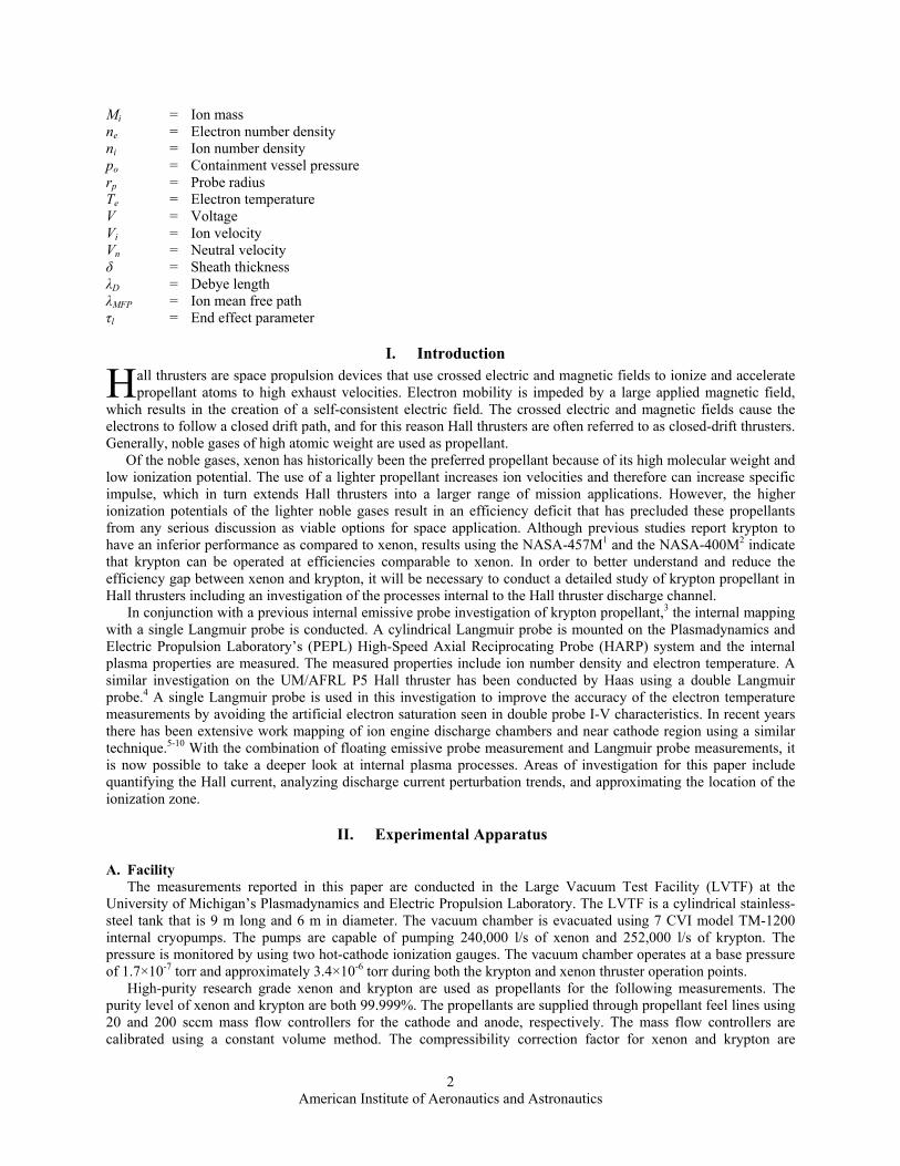
For this experiment, the probe voltage oscillates at high-frequency during the HARP sweep to give a current-voltage curve corresponding to every spatial location. The probe voltage oscillates in a triangle wave pattern at 350 Hz. As the Langmuir probe is swept into the discharge channel, the floating potential (and plasma potential) increases several hundred volts over the length of a few millimeters. In order to capture sufficient data from the ion saturation and electron retarding regimes at every location, an offset voltage is superimposed on the voltage oscillation. This offset allows the probe bias voltage to always oscillate about the floating potential. To ensure that useful data are taken over the entire region, a second shallower set of sweeps is taken with a smaller bias voltage pulse. The voltage pulse is triggered by the HARP position. This probe bias pulsing is illustrated in Fig. 5. In this figure, the plasma potential is shown in black and two bias voltage sweeps are labeled Bias Sweep 1 and 2. The location of the voltage pulse is determined from the internal emissive probe measurement presented previously.3,12
In order to decrease the thruster perturbations it is necessary to increase the HARP speed, decrease the probe
residence time, and decrease the probe size while keeping the probe large enough to ensure probe survival. However, in order to maximize the number of I-V characteristics per length, it is necessary to minimize the HARP speed and maximize the bias oscillation frequency while minimizing the stray capacitance associated with the high-voltage oscillations. Probe resolution can be increased by decreasing the length of the probe tip at the cost of a weaker probe signal and a greater end effect. With all of these considerations in mind, the probe is operated in the following manner.
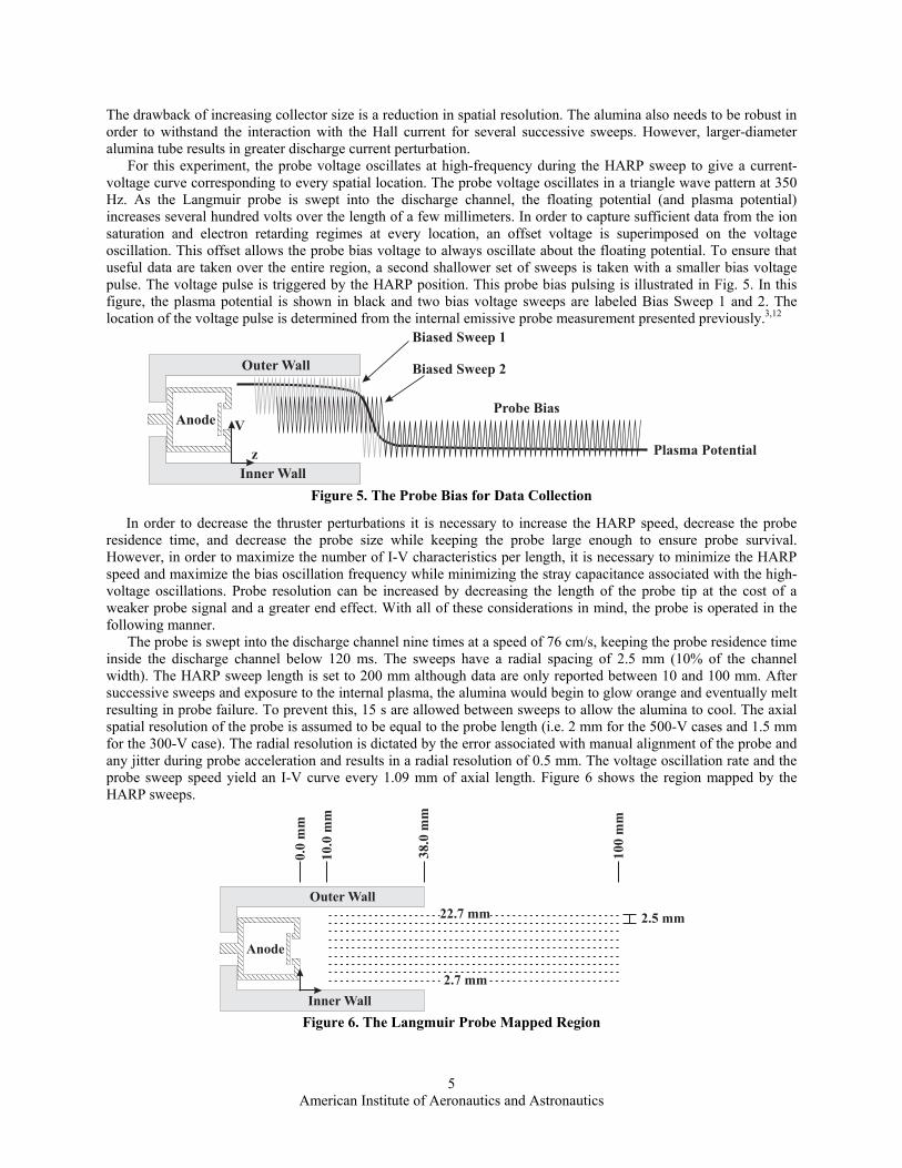
The probe is swept into the discharge channel nine times at a speed of 76 cm/s, keeping the probe residence time inside the discharge channel below 120 ms. The sweeps have a radial spacing of 2.5 mm (10% of the channel width). The HARP sweep length is set to 200 mm although data are only reported between 10 and 100 mm. After successive sweeps and exposure to the internal plasma, the alumina would begin to glow orange and eventually melt resulting in probe failure. To prevent this, 15 s are allowed between sweeps to allow the alumina to cool. The axial spatial resolution of the probe is assumed to be equal to the probe length (i.e. 2 mm for the 500-V cases and 1.5 mm for the 300-V case). The radial resolution is dictated by the error associated with manual alignment of the probe and any jitter during probe acceleration and results in a radial resolution of 0.5 mm. The voltage oscillation rate and the probe sweep speed yield an I-V curve every 1.09 mm of axial length. Figure 6 shows the region mapped by the HARP sweeps.
Anode
Inner Wall
Outer Wall
0.0
mm
38.0
mm
100
mm
10.0
mm
2.7 mm
22.7 mm 2.5 mm
Figure 6. The Langmuir Probe Mapped Region
Anode
Inner Wall
Outer Wall
Plasma Potential
Probe Bias
Biased Sweep 1
Biased Sweep 2
V
z
Figure 5. The Probe Bias for Data Collection

American Institute of Aeronautics and Astronautics
6
-150
-100
-50
0
Vol
tage
, V
8x10⁻³
6420Time, s
-0.4
-0.2
0.0
0.2
0.4 Capacitive C
urrent, mA
Probe Voltage Capacitive Current
Figure 7. Stray Capacitance Effects in Vacuum
Due to the fast, high-voltage oscillation associated with the probe voltage sweep, stray capacitance becomes a concern. However, by characterizing the stray capacitance in a vacuum without the plasma, the classic trend where the capacitive current is equal to capacitance times the derivative of the voltage with respect to time (ICap=C dV/dt) can be easily observed, characterized, and accounted for. Therefore, the raw data can be appropriately corrected and capacitive effects can be effectively removed. An example of the stray capacitance in the Langmuir probe circuit is shown in Fig. 7.
Another possible source of error is thermionic emissions from the probe. If the tungsten probe reaches very high temperatures, it is possible for the probe to emit electron in the same manner as an emissive probe. In these cases, the emitted electron current will appear to be an increased ion current and the I-V characteristic will be shifted. Because the collected ion current is rather small, in comparison to the electron current, this effect is crucially important. Although it is possible for the probe to gain significant heating due to the high-density, high-temperature electrons, very careful selection of the pulse location and modest probe bias voltages should prevent this behavior. A simple method to check for thermionic emission is to compare the floating potentials measured by the Langmuir probe with those measured with a cold emissive probe.3,12 This comparison suggests that the effects of thermionic emission can be ignored in this investigation.
A schematic of Langmuir probe circuit is shown if Fig. 8. The triangle wave and square pulse are sent to a non-inverting summing amplifier, which then sends a signal to a bipolar power supply. This signal is amplified and sent to the Langmuir probe. The Langmuir probe current and voltage are monitored by two AD210 isolation amplifiers and their signals are monitored by a data acquisition system. The probe current, probe voltage, HARP location, and thruster discharge current are acquired at 100 kHz per channel. For each data sweep, 25,000 points are recorder per channel resulting in about 143 points per I-V curve.
For these data, the thruster discharge current perturbations reached a maximum of between 10 and 22%.
Segmented graphite or tungsten coatings are used by other researchers18 to reduce thruster perturbations by decreasing the secondary electron emission from the alumina probe. However, for this experiment, due to the high-power and high-voltage of the Hall thruster operation, the high-temperature graphite paint is unable to withstand the extreme conditions in the discharge channel and no segmented coating is used.
3. Simplifying Assumptions for Probe Analysis
The magnetic field can affect Langmuir probe results by constraining the motion of charged particles (particularly electrons) and subsequently altering the I-V characteristic. As a result, sheath structures around probes are no longer symmetric and can become oblong. A magnetic field can most adversely affect the I-V characteristic by suppressing the electron saturation current, causing the greatest problems near and above the plasma potential. This effect results in difficulty in measuring the electron number density and the plasma potential. Since the ions are
Kepco BOP 500MBipolar Supply
Wavetek Model 19Function Generator
BK Precision3300 Pulse Generator Tektronix
AM501Op-Amp
+
_
10 kW
10 kW10 kW
10 kW
+_ 8.16 MW
131 kW
100 W
Langmuir Probe
+
_
+
_
AD210
+
_
+
_
AD210
CurrentSignal
VoltageSignal
Figure 8. Langmuir Probe Circuit

American Institute of Aeronautics and Astronautics
7
unmagnetized in the Hall thruster discharge chambers, and this study uses the ion saturation current to calculate the ion number density, the ion number density is unaffected by the magnetic field. Also since, the plasma potential is not the focus of this study, any magnetic field effects on plasma potential measurements are not important for this investigation. The magnetic field can also cause anisotropy in the electron energy distribution function (EEDF), which can affect the electron temperature measurement. The magnetic field effects can be considered small based on the following argument. Passoth19 determined that EEDF anisotropy depends upon the ratio B/po, where po is the pressure in the containment vessel. Aikawa20 showed experimentally that EEDF anisotropy is negligible for B/po<2.5×106
G/torr. With a pressure inside the discharge channel on the order of 10-3 torr and using the a maximum magnetic field of 300 G, one finds a B/po ratio of 3×10⁵ G/torr, which is well below the threshold value proposed by Aikawa.
When a cylindrical Langmuir probes is used in a flowing plasmas, one must consider end effects.21 In this situation, an additional parameter becomes important: the probe length to Debye length ratio (lp/λD). Chung, Talbot, and Touryan21 offer the parameter given in Eq. 1 for the relative importance of end effects in the collisionless regime, where Mi is ion mass, Vi is the ion velocity, and lp is the probe length. When τl is much greater than unity the end effects are very small.
( )i
ieB
D
pl V
MTkl 21
λτ = (1)
In the prime area of interest, internal to the discharge channel, the ions have undergone little acceleration and the
end effect is negligible. Consider, the worst case scenario, 100 mm downstream of the anode where the plasma number density and electron temperature are approximately 5×1011 cm-3 and 8 eV, respectively. Assuming that a propellant ion falls through 470 V of potential3,13 as it passes through the acceleration zone, and given the probe dimension in this experiment, the value of τl is greater than 6. Accordingly, the end effects have been neglected in the following analysis.
It is possible that aligning the probe parallel to the electric field may distort the I-V characteristic near the plasma potential by rounding the knee of the I-V curve.19 However, this effect mostly affects the I-V characteristic near the plasma potential, and will have little influence on electron temperature and ion number density measurements. For this reason, this effect is not considered important and has been neglected.
4. Data Analysis
The scientific graphing package Igor is used to analyze these data. The raw Langmuir probe data are first separated into current-voltage pairs resulting in approximately 4,000 I-V characteristics. Each I-V pair is analyzed separately and the extracted plasma properties are then reassembled into one output file. This output file is then plotted in contour maps.
Each I-V curve undergoes three passes with a three-point box smoothing algorithm to smooth the signal and increase the ease of analysis in difficult regions. Internal to the discharge channel, the I-V characteristics sometimes become noisy due to the breathing mode instability creating an oscillation in the probe current. An extreme case of this can be seen if Fig. 9, which shows a breathing mode instability of 20 kHz. In this figure, one can see the raw I-V curve and the I-V curve after the smoothing. Also plotted is the discharge current versus time. The top and bottom axes (Time and Probe Voltage, respectively) correspond point by point so it is possible to see the correlation between the discharge current and probe current. Due to this smoothing, the calculated plasma properties can be considered time averaged and any fluctuation in the ionization zone will be averaged in time.
During the analysis of the I-V characteristic, the floating potential is first calculated and then if possible the plasma potential is measured by finding the maximum of the first derivative of the I-V characteristic. The electron
20
15
10
5
0Pro
be C
urre
nt, m
A
440400360320Probe Voltage, V
12
8
4
0
Discharge C
urrent, A
0.80.60.40.20.0Time, ms
Probe Current Discharge Current Smoothed Probe Current
Figure 9. The Effect of the Breathing Mode on the I-V Characteristics

American Institute of Aeronautics and Astronautics
8
population is assumed to be purely Maxwellian and the ion current is then subtracted from the I-V curve. Based on the floating potential and plasma potential, the electron retarding region is defined and the electron temperature is calculated. The inverse slope of the natural log of electron current versus voltage gives the Maxwellian electron temperature.
The ion saturation current is then calculated. For consistency, the ion saturation current (Ii,sat) is always measured between a voltage range that varies relative to the floating potential. That is to say, if the floating potential is equal to 10 V, then the ion saturation current would equal the average of the ion current between -50 and 0 V. If the floating potential is 300 V, then the ion current would be averaged between 240 and 290 V. Based on the ion saturation current and the electron temperature, the ion number density for the thin sheath assumption (ni,thin) can be calculated by Eq. 2. In this equation, As is the probe collector area.
eB
i
s
satithini Tk
MeA
In
61.0,
, = (2)
The true probe collection area depends upon the thickness of the sheath surrounding the probe. For this reason, it
is necessary to modify the probe collection area to calculate the true ion number density for the thin sheath assumption. Based on the calculated plasma properties, the new probe collection area is calculated and the iteration is continued until convergence is reached. Assuming quasineutrality for the calculation of the Debye length, the sheath thickness (δ) is calculated from Eq. 3 and the sheath collection area is calculated from Eq. 4.22,23 In these equations, Ap is the physical probe surface area.
+
−
−
−= 2ln
21
21ln
2102.1
212
12
1
i
e
i
eD M
mMmλδ (3)
( )pps rAA δ+= 1 (4)
The next step is to calculate the ion number density (ni,OML) based on the OML assumption. This regime is
analyzed by the techniques developed by Laframboise24,25 that assume a cylindrical probe immersed in a cold, collisionless, stationary plasma. In this case, the sheath dimensions are assumed to increase with probe bias such that the collected ion current is affected. In the OML regime, the number density for cylindrical probes is calculated from the slope of the ion current squared versus bias voltage according to Eq. 5.25-27
=
dVdI
eM
An ii
pomli
2
3, 27.121 π
(5)
Chen26 suggests that the OML regime is entered when the ratio of probe radius to Debye length is less than
approximately three. Whereas a probe radius to Debye length ratio of greater than ten indicates that the probe is in the thin sheath regime. Unfortunately, a great deal of these Langmuir probe data fall between the thin and OML regimes. To account for these data, a weighted average (based on the Debye length to probe radius) is used to give smooth transition between these regimes. The analysis techniques used in this investigation can be found in Refs.17, 21, 22, 26, 28-32.
A traditional error estimate of 20% for electron temperature and 50% for ion number density are assumed in this experiment.22 Although the magnitude errors of these measurements are somewhat inaccurate, the relative error should be low and the relative trends are expected to be consistent with the exact properties inside the discharge channel.
III. Results and Discussion
A. Probe Induced Perturbations Much can be learned from simply observing the trends in the thruster perturbations. The statistics of the
discharge current are calculated during each I-V characteristic and the results are mapped in Fig. 10, which shows

American Institute of Aeronautics and Astronautics
9
results from the 500-V xenon case (Point 2, Table 1). The discharge current perturbation is calculated by averaging the discharge current during each I-V characteristic sweep and comparing it to the unperturbed discharge current. Similarly, the discharge current standard deviation is calculated at each spatial location. For every spatial location, a fast Fourier transform of the discharge current is taken to find the dominant current oscillation. This current oscillation, which is referred to as the breathing mode, is also mapped. Superimposed on Fig. 10 are the magnetic field pathlines. Additionally, the boundary of the acceleration zone, which appears in Fig. 15, is overlaid using black circles. These boundaries were found in a previous experiment.3,12
The largest perturbation to the thruster is approximately 22% and occurs near the center of the discharge channel and just upstream of the Hall current and acceleration zone (see Figs. 15 and 16). However, the standard deviation of the discharge current is the highest in the Hall current region and it is also slightly increased near the channel walls. By monitoring the discharge current and with this very simple analysis, one can find important information about the location of the acceleration zone and the Hall current (See Section III.B.4.).
The breathing mode frequency also decreases in the area of high perturbation. When the probe tip is upstream of the Hall current the typical breathing mode oscillation (~22 kHz) decreases to approximately 12 kHz. The breathing
Figure 10. Probe Induced Perturbations for the 500 V, Xenon Case

American Institute of Aeronautics and Astronautics
10
mode33,34 is a low-frequency discharge current instability related to predator-prey relation between the electron and neutral propellant atoms. Due to the large magnetic field near the channel exit, the electron conductivity is low, resulting in a large electric field in this region, and a high ionization rate that acts to deplete the neutral density. The front of the neutral flow retreats upstream to a region where the ionization rate is low. As the front of the neutral flow once again moves downstream into the region of high electric field, the neutral density is replenished and the ionization rate increases, thus the process is repeated. This behavior results in an oscillation in the location of the ionization zone and an oscillation in the electric field. Fife et al.35 offer a simple predator-prey model that gives the relation for the breathing mode frequency shown in Eq. 6, where Li is the length of the ionization zone, and Vn is the neutral velocity.
iniB LVVf π2= (6)
As the tip of the probe passes thought the Hall current, the ionization process is disturbed, resulting in greater oscillation in the electric field and the ionization zone location. Although in a time-averaged sense, the ionization and acceleration zone are probably not strongly affected by the presence of the probe tip. As the tip continues to move upstream of the acceleration zone, the probe shaft interacts with the Hall current. The presence of the alumina probe shaft increases the electron collisions, resulting in increased cross-field mobility and hence increased electron flow to the anode, which manifests as an increased discharge current. Moreover, the high secondary electron emission from the electron-alumina interaction further increases the electron flow toward the anode. This enhanced electron conductivity in the Hall current region, decreases the magnitude of and broadens the high-electric field region. At least local to the probe, this effect acts to decrease the ionization rate and increase the length of the ionization zone since the ionization rate is inversely proportional to the ionization zone length.35 The increase in ionization zone length results in the decreased breathing mode frequency observed in Fig. 10. Another possible explanation is that due to the probe shaft obstructing the flow of the Hall current, a great deal of energy is deposited into the alumina shaft. This energy loss in the plasma (cooling) decreases the ionization rate and increases the ionization zone length. Again, this decrease in ionization rate and increase in the ionization zone length decreases the breathing mode frequency.
Because the Hall current is so focused in the center of the discharge channel, there is very little perturbation when the probe is swept near the walls. Near the center of the channel, it is difficult to tell how damaging the thruster perturbations are to the Langmuir probe results. Most of the thruster perturbation is caused in the Hall current region, when the probe collector is upstream of the Hall current. Since the probe collector is not located in this region of high disturbance, it is conceivable that the plasma measurements are less affected by these perturbations than feared.
B. Operation Points A list of the operating conditions appears in Table 1. Point 1 uses xenon propellant and operates at 300 V and
102.4 sccm. Points 2 and 3 compare xenon and krypton operation at a discharge voltage of 500 V and discharge current of 9.44 A. Point 4 is identical to the 500-V krypton point except that it is operated using the same magnetic coil settings as the 500-V xenon point. The internal mapping is not conducted for krypton at 300 V due to the relatively poor performance of krypton at low voltages. Due to low propellant utilization, krypton performance is relatively low below a discharge voltage of approximately 500 V.36 For each operation point the electron temperatures and ion number densities are shown. The magnetic coil settings for these operation points were found in a previous experiment by calculating real-time thruster efficiencies as a function of thruster settings. The optimum magnetic currents are found when the efficiency is maximized and not when discharge current is minimized.
Table 1. Thruster Operating Conditions Point
# Propellant Vk, V
Vd, V
Id, A
Anode Flow, sccm
Cathode Flow, sccm
Inner Coil, A
Outer Coil, A
Trim Coil, A
1 Xenon -12.8 300 8.54 102.4 10.24 1.88 2.21 -0.51 2 Xenon -12.9 500 9.44 102.4 10.24 2.90 2.87 -0.87 3 Krypton -15.1 500 9.44 126.6 12.65 1.79 2.27 -0.43 4 Krypton -15.7 500 10.15 126.6 12.65 2.90 2.87 -0.87
American Institute of Aeronautics and Astronautics
11
For each operation point the boarders of the acceleration and ionization zones are also plotted (Figs. 12, 15, and 18). The acceleration zones are based on floating emissive probe measurements reported in previous papers.3,12 The acceleration zone is located between 10 and 90% of the total potential fall. The ionization zone boarders are calculated by finding the point at which the ion number density is equal to 40% of the maximum ion number density in the discharge channel. This method is used as a simple way of approximating the location of the ionization zones and to identify general trends in these data. In reality, the actual ionization zone is dictated by the location of high ion production. Finding the ionization zone precisely requires solving the two-dimensional ion velocity field and then measuring the ion production by solving the ion continuity equation. Although this analysis will be conducted at a later date, it is out of the scope of this paper. For brevity, the approximate ionization zone will be simply referred to as the “ionization zone” in the remainder of the paper.
For each operation point, the electric fields calculated with a floating emissive probe3,12 are used in conjunction with the Langmuir probe results to calculate the Hall current density. The Hall current density is calculated assuming quasineutral plasma and using Eq. 7. Since the magnetic field approaches zero inside the discharge channel, a singularity can occur at these locations. To avoid this problem, the E×B current is only calculated in cases where the electrons are magnetized. That is, the electron gyroradius is ten times smaller than the discharge channel width. Since no emissive probe data exist for Point 4, this analysis is not conducted for this condition.
2B
BEenJ iBE v
vv×
=× (7)
1. 300-V Xenon Case
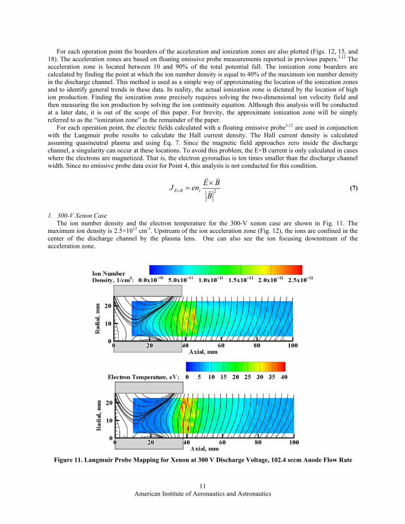
The ion number density and the electron temperature for the 300-V xenon case are shown in Fig. 11. The maximum ion density is 2.5×1012 cm-3. Upstream of the ion acceleration zone (Fig. 12), the ions are confined in the center of the discharge channel by the plasma lens. One can also see the ion focusing downstream of the acceleration zone.
Figure 11. Langmuir Probe Mapping for Xenon at 300 V Discharge Voltage, 102.4 sccm Anode Flow Rate
American Institute of Aeronautics and Astronautics
12
The electron temperature increases in the acceleration zone and reaches a maximum of 40 eV. Electron temperature is strongly tied to the magnetic fieldlines, which appear to be approximately isothermal in electron temperature as expected. This finding is true in the entire mapped region and is no surprise since the electrons should diffuse freely along the B-field lines.
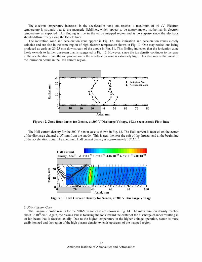
The ionization zone and acceleration zone appear in Fig. 12. The ionization and acceleration zones closely coincide and are also in the same region of high electron temperature shown in Fig. 11. One may notice ions being produced as early as 20-25 mm downstream of the anode in Fig. 11. This finding indicates that the ionization zone likely extends to further upstream than is suggested in Fig. 12. However, since the ion density continues to increase in the acceleration zone, the ion production in the acceleration zone is extremely high. This also means that most of the ionization occurs in the Hall current region.
The Hall current density for the 300-V xenon case is shown in Fig. 13. The Hall current is focused on the center of the discharge channel at 37 mm from the anode. This is near the near the exit of the thruster and at the beginning of the acceleration zone. The maximum Hall current density is approximately 106 A/m2.
2. 500-V Xenon Case The Langmuir probe results for the 500-V xenon case are shown in Fig. 14. The maximum ion density reaches
about 3×1012 cm-3. Again, the plasma lens is focusing the ions toward the center of the discharge channel resulting in an ion beam that is focused axially. Due to the higher temperature in the higher voltage operation, xenon is more easily ionized and the region of the high plasma density extends upstream of the mapped region.
Figure 13. Hall Current Density for Xenon, at 300 V Discharge Voltage
25
20
15
10
5
0
Rad
ial,
mm
80706050403020100
Axial, mm
20100 30
Ionization Zone Acceleration Zone
Figure 12. Zone Boundaries for Xenon, at 300 V Discharge Voltage, 102.4 sccm Anode Flow Rate

American Institute of Aeronautics and Astronautics
13
The maximum electron temperature exceeds 40 eV in the bulk of the discharge channel and reaching a maximum
of 50 eV. The region of high electron temperature is clearly outlined by the magnetic field lines, which is expected since the electrons freely move along the B-field lines and are impeded across the field lines. Just as in the 300-V case, the electrons are very close to isothermal along the B-field lines.
Figure 15 shows the acceleration and ionization zones for Point 2. Similar to the 300-V case, the ionization zone overlaps with a great deal of the acceleration zone and Hall current region. Although at the higher voltage, the region of high ion density extends further upstream than in the 300-V xenon case. The highest ionization is located in the center of the discharge channel.
The Hall current density for the 500-V xenon case is shown in Fig. 16. As with the 300-V case, the Hall current
is focused on the center of the discharge channel and located at the beginning of the acceleration zone. The maximum Hall current is density is approximately 1.8×10⁶ A/m2, 80% higher than the 300-V case. The Hall current density maximum is approximately 34 mm from the anode at the beginning of the acceleration zone. This larger Hall current is expected since the large axial electric field should be directly proportional to the discharge voltage.
25
20
15
10
5
0
Rad
ial,
mm
80706050403020100
Axial, mm
20100 30
Ionization Zone Acceleration Zone
Figure 15. Zone Boundaries for Xenon, at 500 V Discharge Voltage, 102.4 sccm Anode Flow Rate
Figure 14. Langmuir Probe Mapping for Xenon at 500 V Discharge Voltage, 102.4 sccm Anode Flow Rate

American Institute of Aeronautics and Astronautics
14
3. 500-V Krypton Case with Matched Power Case
Figure 17 shows the Langmuir probe results for Point 3. The maximum ion number density reaches 4×1012 cm-3, which is larger than the xenon operation points. Unlike the xenon cases, the majority of the krypton ionization occurs upstream of the acceleration zone, as opposed to in the Hall current region. Downstream of the acceleration zone, the ion number densities contours show a slight focusing toward the centerline of the thruster as opposed to predominantly axially as seen in the xenon cases. This result is consistent with the focusing effects shown by the internal emissive probe results.3 The highest plasma density is located in the center of the discharge channel near the anode in a region where the magnetic mirror effect (or “magnetic bottle”) is particularly strong. This finding is not entirely surprising since the magnetic mirror acts to confine the electrons and increase the electron number density in the center of the “bottle”.37 The increased electron density increases the ionization collision rate and hence dictates the location of the ionization zone. This correlation between magnetic field topology and ion production is an interesting trend and an obvious area for future study.
Electron temperature reaches a maximum of 60 eV near the outer wall of the discharge channel and is around 45
eV in the bulk of the discharge channel. This electron temperature for krypton is slightly higher than the electron
Figure 16. Hall Current Density for Xenon, at 500 V Discharge Voltage
Figure 17. Langmuir Probe Mapping for Krypton at 500 V Discharge Voltage, 126.6 sccm Anode Flow Rate

American Institute of Aeronautics and Astronautics
15
temperature in the xenon case although both have approximately the same magnitude. Inside and downstream of the acceleration zone, the magnetic field pathlines again appear to approximately match electron isothermal lines.
Figure 18 shows the acceleration and ionization zones for Point 3. The region of high plasma density is located entirely upstream of the acceleration zone, indicating that most of ionization occurs in the upstream region. The low ionization rate in the Hall current region is likely due to the krypton’s high ionization potential and low residence time. It is unclear what role the magnetic field topology plays in influencing this behavior. Although the location of the krypton ionization zone may be unexpected, its location is consistent with retarding potential analyzer measurements, which indicate that the krypton ion velocity dispersion is lower than xenon’s.13
Krypton’s slightly larger maximum electron temperature is consistent with the location of the krypton ionization
zone. Since the ion production in the acceleration zone is lower in the krypton case, the electrons energy loss to ionization is small resulting in a slightly higher maximum electron temperature. With this said, the difference in electron temperature in the krypton and xenon case is not significant, which indicates that the energy loss to ionization may not the dominant loss term associated with the electron temperature saturation.38-40
The Hall current density for the 500-V krypton case is shown in Fig. 19. The maximum Hall current is approximately 1.8×10⁶ A/m2 and is focused into the center of the discharge channel. The maximum Hall current is at the start of the acceleration zone, which is located around 35 mm from the anode. These results are similar to the 500-V xenon results although the size of the Hall current region is slightly smaller than the xenon case.
4. 500-V Krypton Case with Matched B-Field
The results from the Langmuir Probe investigation of Point 4 are shown in Fig. 20. Just as in the power-matched krypton case, the B-field matched case has a maximum number density of 4×1012 cm-3. By following the lines of constant density, it can be seen that the ions are accelerated more along the center of discharge channel than in the power-matched krypton case. Consequently, it appears that the beam divergence may be improved for the B-field matched case. Similar to the power-matched case, the ion number density is highest in the middle of a strong magnetic mirror in the center-rear of the discharge channel.
The electron temperatures are approximately 45 eV on average and reach a maximum of 60 eV upstream of the acceleration zone. The data collected at this condition are more erratic than the other data sets due to the large
25
20
15
10
5
0
Rad
ial,
mm
80706050403020100
Axial, mm
20100 30
Ionization Zone Acceleration Zone
Figure 18. Zone Boundaries for Krypton, at 500 V Discharge Voltage, 126.6 sccm Anode Flow Rate
Figure 19. Hall Current Density for Krypton, at 500 V Discharge Voltage

American Institute of Aeronautics and Astronautics
16
discharge current oscillations associated with Point 4 operation. Nevertheless, both trends and values of the data are consistent with the power-matched krypton case.
The discharge current standard deviation is shown in Fig. 21. This figure displays the very large discharge
oscillations with these non-optimized magnet settings. Just as in Fig. 10, the magnetic field pathlines are plotted over the contour map. As a point of reference, the acceleration zone boundaries from the 500-V xenon case are also overlaid on the contour plot. Again, the region of highest current oscillation indicates the location of the Hall current. This figure shows that for this krypton case, the Hall current and acceleration zone locations are very similar to the xenon case, which implies that the magnetic field alone is enough to match the acceleration zone regardless of the propellant. However, because of the different ionization properties of krypton, the ionization is not stable, resulting in large current oscillations and lower thruster performance. In other words, the different properties of krypton and xenon mandate that the thruster operate with different magnetic field topologies to optimize the performance of each propellant.
Figure 20. Langmuir Probe Mapping for Krypton at 500 V Discharge Voltage, 126.6 sccm Anode Flow Rate,
and with Matched Magnetic Field
Figure 21. Probe Induced Perturbations for the 500-V Krypton Case with Matched B-field

American Institute of Aeronautics and Astronautics
17
IV. Conclusions Internal plasma properties including electron temperature and ion number density have been mapped for cases
comparing xenon and krypton propellants. The electron temperatures for xenon are found to reach a maximum of 40 eV for the 300-V case and 50 eV for the 500-V case. The 500-V krypton operation points have a higher maximum electron temperature of 60 eV. The maximum ion number densities are approximately 3×10¹² and 4×1012 cm-3 for xenon and krypton, respectively.
The effect of the magnetic field topology is shown to be centrally important to the behavior internal to the Hall thruster. The plasma lens is shown to focus ions toward the center of the discharge channel, which results in a substantial contribution to the reduction of beam divergence. The electrons are also isothermal along the magnetic field pathlines. This last finding is of no surprise since electrons diffuse freely along the magnetic field lines and are impeded across the field lines.
The location and magnitude of the Hall current is successfully shown for the different operating conditions. The maximum Hall current density is shown to be between 106-2×10⁶ A/m2. The Hall current is focused in the center of the discharge channel near the exit. The krypton case has a slightly smaller Hall current region.
This study also revealed useful information about the ionization zone inside the discharge channel. For the xenon cases, ionization is largely connected to the Hall current, although the ionization zone begins farther upstream for high-voltage operation. When ionization occurs upstream of the Hall current region, the peak ionization is located at the center of the magnetic mirror. For the krypton case, the majority of the ionization occurs at the center of a strong magnetic mirror. There is very little krypton ionization in the Hall current region. With fewer ionizing collisions in the Hall current region, it is not surprising that the electron temperature is slightly higher for the krypton cases.
When the krypton propellant is operated with the same magnetic field topology as the xenon case, the acceleration zone and Hall current zone are in the same location and there appears to be improved beam divergence. However, due to the different ionization properties of krypton, the discharge current oscillations are very high and thruster efficiency is not optimized.
A simple discharge current analysis is shown to yield valuable information about discharge channel phenomena. Specifically, the location of the acceleration zone and the Hall current region can be found by analyzing thruster perturbations and oscillations. This analysis also sheds light on probe-plasma interaction during probe insertion. When the probe is inside the discharge channel, the Hall current is disrupted, resulting in increased thruster perturbations and a decrease in the breathing mode frequency.
Acknowledgments We would like to thank the Association Francois-Xavier Bagnoud for their financial support during Mr. Jesse
Linnell’s graduate studies. We would also like to thank Dr. Daniel Herman and Dr. Josh Rovey for their valuable discussion.
References 1Jacobson, D. T., Manzella, D. H., "50 KW Class Krypton Hall Thruster Performance," 39th AIAA/ASME/SAE/ASEE Joint
Propulsion Conference, AIAA-2003-4550, Huntsville, AL, July 20-23, 2003. 2Peterson, P. Y., Jacobson, D. T., Manzella, D. H., John, J. W., "The Performance and Wear Characterization of a High-
Power High-Isp NASA Hall Thruster," 41st AIAA/ASME/SAE/ASEE Joint Propulsion Conference, AIAA-2005-4243, Tucson, Arizona, 10-13 July 2005.
3Linnell, J. A., Gallimore, A. D., "Internal Plasma Structure Measurements of a Hall Thruster Using Xenon and Krypton Propellant," 29th International Electric Propulsion Conference, IEPC-2005-024, Princeton, NJ, October 31 - November 4, 2005.
4Haas, J. M., Gallimore, A. D., "An Investigation of Internal Ion Number Density and Electron Temperature Profiles in a Laboratory-Model Hall Thruster," 36th AIAA/ASME/SAE/ASEE Joint Propulsion Conference, AIAA-2000-3422, Huntsville, AL, July 16-19.
5Rovey, J. L., "A Multiple-Cathode, High-Power, Rectangular Ion Thruster Discharge Chamber for Increasing Thruster Lifetime," Thesis, Dept. of Aerospace Engineering, University of Michigan, Ann Arbor, 2006.
6Herman, D. A., Gallimore, A. D., "Discharge Chamber Plasma Structure of a 40-cm NEXT-type Ion Engine," 41st AIAA/ASME/SAE/ASEE Joint Propulsion Conference, AIAA-2005-4250, Tucson, AZ, July 10-13, 2005.
7Sengupta, A., Goebel, D. M., Fitzgerald, D., Owens, A., Tynan, G., Doerner, R., "Experimentally Determined Neutral Density and Plasma Parameters in a 30cm Ion Engine," 40th AIAA/ASME/SAE/ASEE Joint Propulsion Conference, AIAA-2004-3613, Fort Lauderdale, FL, July 11-14, 2004.
8Jameson, K. K., Goebel, D. M., Watkins, R. M., "Hollow Cathode and Thruster Discharge Chamber Plasma Measurements Using High-Speed Scanning Probes," 29th International Electric Propulsion Conference, IEPC-2005-269, Princeton, NJ, Oct. 31-Nov. 4, 2005.

American Institute of Aeronautics and Astronautics
18
9Goebel, D. M., Jameson, K. K., Watkins, R. M., Katz, I., "Hollow Cathode and Keeper-Region Plasma Measurements using Ultra-fast Miniature Scanning Probes," 40th AIAA/ASME/SAE/ASEE Joint Propulsion Conference, AIAA-2004-3430, Fort Lauderdale, FL, July 11-14, 2004.
10Martin, R. H., Farnell, C. C., Williams, J. D., "Direct and Remote Measurements of Plasma Properties nearby Hollow Cathodes," 29th International Electric Propulsion Conference, IEPC-2005-294, Princeton, NJ, Oct. 31-Nov. 4, 2005.
11Hofer, R. R., "Development and Characterization of High-Efficiency, High-Specific Impulse Xenon Hall Thrusters," Doctoral Thesis, Dept. of Aerospace Engineering, University of Michigan, Ann Arbor, MI, 2004.
12Linnell, J. A., Gallimore, A. D., "Internal Plasma Structure Measurements of a Hall Thruster Using Plasma Lens Focusing," 41st AIAA/ASME/SAE/ASEE Joint Propulsion Conference, AIAA-2005-4402, Tucson, Arizona, July 10-13, 2005.
13Linnell, J. A., Gallimore, A. D., "Efficiency Analysis of a Hall Thruster Operating with Krypton and Xenon," Journal of Propulsion and Power, "Efficiency Analysis of a Hall Thruster Operating with Krypton and Xenon", Accepted for Publication, 2006.
14Haas, J. M., "Low-perturbation Interrogation of the Internal and Near-field Plasma Structure of a Hall Thruster Using a High-Speed Probe Positioning System," Thesis, Dept. of Aerospace Engineering, University of Michigan, 2001.
15Haas, J. M., Gallimore, A. D., McFall, K., Spanjers, G., "Development of a High-Speed, Reciprocating Electrostatic Probe System for Hall Thruster Interrogation," Review of Scientific Instruments, 71, 11, 2000, 4131-4138.
16Langmuir, I., "The Interaction of Electron and Positive Ion Space Charges in Cathode Sheaths," Physical Review, 33, 6, 1929, 954-989.
17Mott-Smith, H. M., Langmuir, I., "The Theory of Collectors in Gaseous Discharges," Physical Review, 28, 4, 1926, 727–763.
18Staack, D., Raitses, Y., Fisch, N. J., "Sheilded Electrostatic Probe for Nonperturbing Plasma Measurements in Hall Thrusters," Review of Scientific Instruments, 75, 2, 2004, 393-399.
19Passoth, E., Kudrna, P., Csambal, C., Behnke, J. F., Tichy, M., Helbig, V., "An Experimental Study of Plasma Density Determination by a Cylindrical Langmuir Probe at Different Pressures and Magnetic Fields in a Cylindrical Magnetron Discharge in Heavy Rare Gases," Journal of Physics D: Applied Physics, 30, 1997, 1763-1777.
20Aikawa, H., "The Measurement of the Anisotropy of Electron Distribution Function of a Magnetized Plasma," Journal of the Physical Society of Japan, 40, 6, 1976, 1741-1749.
21Chung, P. M., Talbot, L., Touryan, K. J., "Electric Probes in Stationary and Flowing Plasma: Part 1. Collisionless and Transitional Probes," AIAA Journal, 12, 2, 1974, 133-144.
22Hutchinson, I. H., Principles of Plasma Diagnostics, Second Ed., Cambridge University Press, Cambridge, 2002. 23Schott, L., Plasma Diagnostics, North-Holland Publishing Company, Amsterdam, Netherlands, 1968. 24Laframboise, J. G., Parker, L. W., "Probe Design for Orbit-Limited Current Collection," Physics of Fluids, 16, 5, 1973,
629-636. 25Laframboise, J. G., "Theory of Spherical and Cylindrical Langmuir probes in a Collisionless, Maxwellian Plasma at Rest,"
UTIAS Report No. 100, Institute for Aerospace Studies, University of Toronto, Toronto, Canada, June 1966. 26Chen, F. F., "Electric Probes," Plasma Diagnostic Techniques, R. H. Huddlestone and S. L. Leonard, eds., Academic Press,
New York,1965. 27Steinbrüchel, C., Journal of the Electrochemical Society, 130, 648. 28Hershkowitz, N., "How Langmuir Probes Work," Plasma Diagnostics, O. Auciello and D. L. Flamm, eds., Academic Press,
Inc., Boston, pp. 113-184,1989. 29Chen, F. F., "Langmuir Probe Analysis for High Density Plasmas," Physics of Plasmas, 8, 6, 2001, 3029-3041. 30Herman, D. A., "The Use of Electrostatic Probes to Characterize the Discharge Plasma Structure and Identify Discharge
Cathode Erosion Mechanisms in Ring-Cusp Ion Thrusters," Thesis, Dept. of Aerospace Engineering, University of Michigan, Ann Arbor, 2005.
31Peterson, E. W., Talbot, L., "Collisionless Electrostatic Single-Probe and Double Probe Measurements," AIAA Journal, 8, 12, 1970, 2215-2219.
32Narasimhan, G., Steinbruchel, C., "Analysis of Langmuir Probe Data: Analytical Parametrization, and the Importance of the End Effect," Journal of Vacuum Science and Technology A, 19, 1, 2001, 376-378.
33Choueiri, E. Y., "Plasma Oscillations in Hall Thrusters," Physics of Plasmas, 8, 4, 2001, 1411-1426. 34Boeuf, J. P., Garrigues, L., "Low Frequency Oscillations in a Stationary Plasma Thruster," Journal of Applied Physics, 84,
7, 1998, 3541-3554. 35Fife, J. M., Martinez-Sanchez, M., Szabo, J., "A Numerical Study of Low-Frequency Discharge Oscillations in Hall
Thrusters," 33rd AIAA/ASME/SAE/ASEE Joint Propulsion Conference, 1997-3052, Seattle, WA, July 6-9, 1997. 36Linnell, J. A., Gallimore, A. D., "Krypton Performance Optimization in High Voltage Hall Thrusters," Journal of
Propulsion and Power, Accepted for Publication, 2006. 37King, L. B., "A (Re-) examination of Electron Motion in Hall Thruster Fields," 29th International Electric Propulsion
Conference, IEPC-2005-258, Princeton, NJ, Oct. 31 – Nov. 4, 2005. 38Raitses, Y., Staack, D., Smirnov, A., Fisch, N. J., "Space Charge Saturated Sheath Regime and Electron Temperature
Saturation in Hall Thrusters," Physics of Plasmas, 12, 073507, 2005. 39Ahedo, E., Escobar, D., "Influence of Design and Operation Parameters on Hall Thruster Performances," Journal of Applied
Physics, 96, 2, 2004, 983-992. 40Barral, S., Makowski, K., Peradzyski, Z., Gascon, N., Dudeck, M., "Wall Material Effects in Stationary Plasma Thrusters.
II. Near-Wall and In-Wall Conductivity," Physics of Plasmas, 10, 10, 2003, 4137-4152.