Internal Forces and Moments Solved Problems
19
1 © 2019 Montogue Quiz Quiz SM104 Internal Forces and Moments Lucas Montogue Problems PROBLEM ❶ The simply supported beam shown in the figure below carries two concentrated loads. Which of the following pairs of graphs best approximates the shear and bending moment diagrams for this system? A) B)
Transcript of Internal Forces and Moments Solved Problems

1 © 2019 Montogue Quiz
Quiz SM104
Internal Forces and Moments Lucas Montogue
Problems
PROBLEM ❶
The simply supported beam shown in the figure below carries two concentrated loads. Which of the following pairs of graphs best approximates the shear and bending moment diagrams for this system?
A)
B)

2 © 2019 Montogue Quiz
C)
D)
PROBLEM ❷ (Beer et al., 2013, w/ permission)
Consider beam AB shown below. What are the maximum values for shear force and bending moment for this system?
A) |𝑉𝑉max| = 365 lb and |𝑀𝑀max| = 3510 lb∙in. B) |𝑉𝑉max| = 365 lb and |𝑀𝑀max| = 5110 lb∙in. C) |𝑉𝑉max| = 515 lb and |𝑀𝑀max| = 3510 lb∙in. D) |𝑉𝑉max| = 515 lb and |𝑀𝑀max| = 5110 lb∙in.
PROBLEM ❸ (Hibbeler, 2010, w/ permission)
Which of the following graphs best illustrates the shear force and bending moment diagrams for the beam illustrated below?

3 © 2019 Montogue Quiz
A)
B)
C)
D)
PROBLEM ❹ (Merriam & Kraige, 2002, w/ permission)
Consider a beam with the loading pattern shown below. Find the distance x, measured from the left end, for which the bending moment is maximum.
A) 𝑥𝑥 = 4.47 ft B) 𝑥𝑥 = 6.12 ft C) 𝑥𝑥 = 7.54 ft D) 𝑥𝑥 = 10.0 ft
4 © 2019 Montogue Quiz
PROBLEM ❺ (Beer et al., 2013, w/ permission)
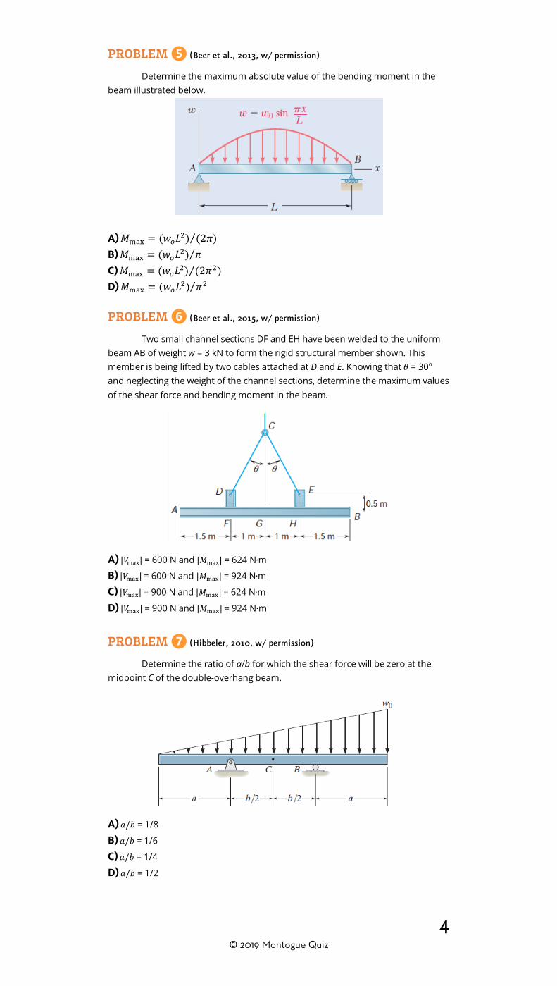
Determine the maximum absolute value of the bending moment in the beam illustrated below.
A) 𝑀𝑀max = (𝑤𝑤𝑜𝑜𝐿𝐿2) (2𝜋𝜋)⁄ B) 𝑀𝑀max = (𝑤𝑤𝑜𝑜𝐿𝐿2) 𝜋𝜋⁄ C) 𝑀𝑀max = (𝑤𝑤𝑜𝑜𝐿𝐿2) (2𝜋𝜋2)⁄ D) 𝑀𝑀max = (𝑤𝑤𝑜𝑜𝐿𝐿2) 𝜋𝜋2⁄ PROBLEM ❻ (Beer et al., 2015, w/ permission)
Two small channel sections DF and EH have been welded to the uniform beam AB of weight w = 3 kN to form the rigid structural member shown. This member is being lifted by two cables attached at D and E. Knowing that 𝜃𝜃 = 30o and neglecting the weight of the channel sections, determine the maximum values of the shear force and bending moment in the beam.
A) |𝑉𝑉max| = 600 N and |𝑀𝑀max| = 624 N∙m B) |𝑉𝑉max| = 600 N and |𝑀𝑀max| = 924 N∙m C) |𝑉𝑉max| = 900 N and |𝑀𝑀max| = 624 N∙m D) |𝑉𝑉max| = 900 N and |𝑀𝑀max| = 924 N∙m
PROBLEM ❼ (Hibbeler, 2010, w/ permission)
Determine the ratio of a/b for which the shear force will be zero at the midpoint C of the double-overhang beam.
A) 𝑎𝑎/𝑏𝑏 = 1/8 B) 𝑎𝑎/𝑏𝑏 = 1/6 C) 𝑎𝑎/𝑏𝑏 = 1/4 D) 𝑎𝑎/𝑏𝑏 = 1/2

5 © 2019 Montogue Quiz
PROBLEM ❽ (Hibbeler, 2010, w/ permission)
Determine the internal normal force, shear force, and moment at point E of the two-member frame shown. True or false?
1. ( ) The absolute value of the internal normal force at E is less than 1 kN.
2.( ) The absolute value of the shear force at E is less than 1 kN. 3. ( ) The absolute value of the internal moment at E is less than 1.2 kN∙m. PROBLEM ❾ (Hibbeler, 2010, w/ permission)
If L = 9 m, the beam will fail when the maximum shear force is Vmax = 5 kN or the maximum bending moment is Mmax = 22 kN∙m. Determine the largest couple moment M0 the beam will support.
A) M0 = 22 kN∙m B) M0 = 44 kN∙m C) M0 = 66 kN∙m D) M0 = 88 kN∙m
PROBLEM ❿ (Hibbeler, 2010, w/ permission)
Determine the largest intensity w0 of the distributed load that the beam can support if the beam can withstand a maximum shear force Vmax = 1200 lb and a maximum bending moment of Mmax = 600 lb∙ft.
A) w = 13.9 lb/ft B) w = 21.8 lb/ft C) w = 32.5 lb/ft D) w = 44.1 lb/ft
6 © 2019 Montogue Quiz
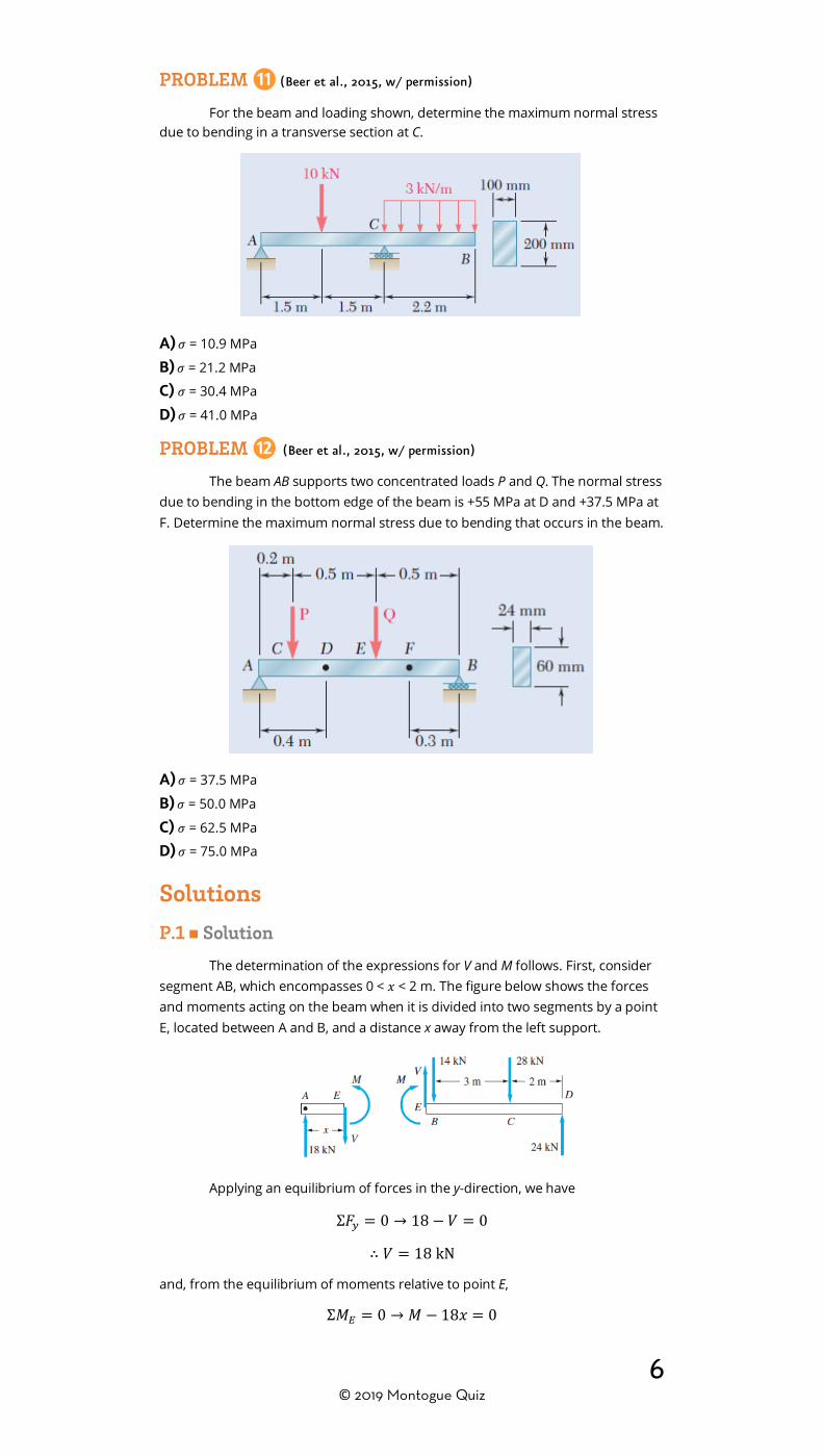
PROBLEM ⓫ (Beer et al., 2015, w/ permission)
For the beam and loading shown, determine the maximum normal stress due to bending in a transverse section at C.
A) 𝜎𝜎 = 10.9 MPa B) 𝜎𝜎 = 21.2 MPa C) 𝜎𝜎 = 30.4 MPa D) 𝜎𝜎 = 41.0 MPa
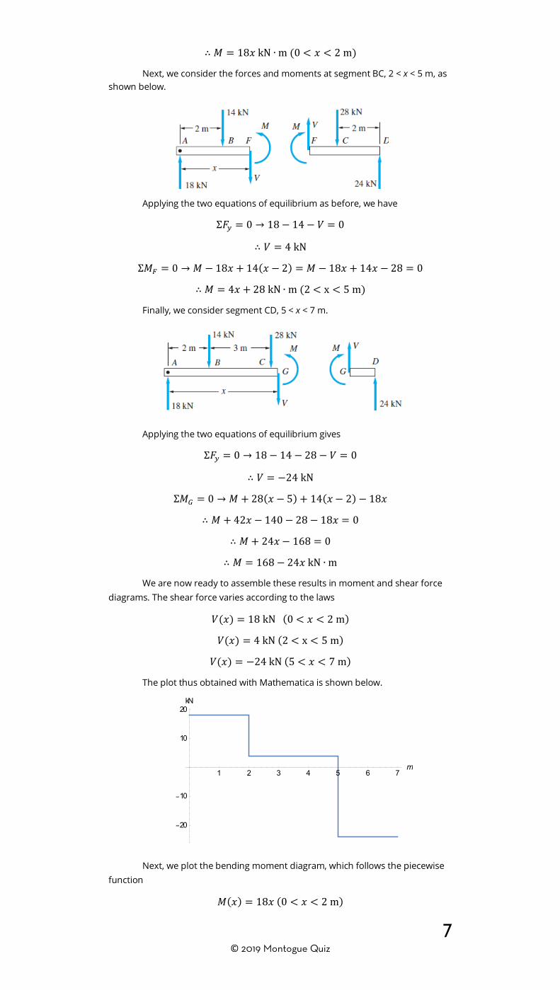
PROBLEM ⓬ (Beer et al., 2015, w/ permission)
The beam AB supports two concentrated loads P and Q. The normal stress due to bending in the bottom edge of the beam is +55 MPa at D and +37.5 MPa at F. Determine the maximum normal stress due to bending that occurs in the beam.
A) 𝜎𝜎 = 37.5 MPa B) 𝜎𝜎 = 50.0 MPa C) 𝜎𝜎 = 62.5 MPa D) 𝜎𝜎 = 75.0 MPa
Solutions
P.1 ■ Solution
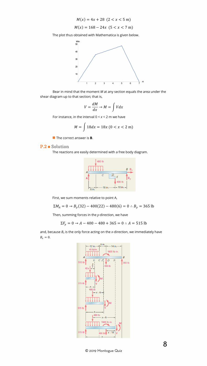
The determination of the expressions for V and M follows. First, consider segment AB, which encompasses 0 < 𝑥𝑥 < 2 m. The figure below shows the forces and moments acting on the beam when it is divided into two segments by a point E, located between A and B, and a distance x away from the left support.
Applying an equilibrium of forces in the y-direction, we have
Σ𝐹𝐹𝑦𝑦 = 0 → 18 − 𝑉𝑉 = 0
∴ 𝑉𝑉 = 18 kN
and, from the equilibrium of moments relative to point E,
Σ𝑀𝑀𝐸𝐸 = 0 → 𝑀𝑀 − 18𝑥𝑥 = 0
7 © 2019 Montogue Quiz
∴ 𝑀𝑀 = 18𝑥𝑥 kN ∙ m (0 < 𝑥𝑥 < 2 m)
Next, we consider the forces and moments at segment BC, 2 < x < 5 m, as shown below.
Applying the two equations of equilibrium as before, we have
Σ𝐹𝐹𝑦𝑦 = 0 → 18 − 14 − 𝑉𝑉 = 0
∴ 𝑉𝑉 = 4 kN
Σ𝑀𝑀𝐹𝐹 = 0 → 𝑀𝑀 − 18𝑥𝑥 + 14(𝑥𝑥 − 2) = 𝑀𝑀 − 18𝑥𝑥 + 14𝑥𝑥 − 28 = 0
∴ 𝑀𝑀 = 4𝑥𝑥 + 28 kN ∙ m (2 < x < 5 m)
Finally, we consider segment CD, 5 < x < 7 m.
Applying the two equations of equilibrium gives
Σ𝐹𝐹𝑦𝑦 = 0 → 18 − 14 − 28 − 𝑉𝑉 = 0
∴ 𝑉𝑉 = −24 kN
Σ𝑀𝑀𝐺𝐺 = 0 → 𝑀𝑀 + 28(𝑥𝑥 − 5) + 14(𝑥𝑥 − 2)− 18𝑥𝑥
∴ 𝑀𝑀 + 42𝑥𝑥 − 140 − 28 − 18𝑥𝑥 = 0
∴ 𝑀𝑀 + 24𝑥𝑥 − 168 = 0
∴ 𝑀𝑀 = 168 − 24𝑥𝑥 kN ∙ m
We are now ready to assemble these results in moment and shear force diagrams. The shear force varies according to the laws
𝑉𝑉(𝑥𝑥) = 18 kN (0 < 𝑥𝑥 < 2 m)
𝑉𝑉(𝑥𝑥) = 4 kN (2 < x < 5 m)
𝑉𝑉(𝑥𝑥) = −24 kN (5 < 𝑥𝑥 < 7 m)
The plot thus obtained with Mathematica is shown below.
Next, we plot the bending moment diagram, which follows the piecewise function
𝑀𝑀(𝑥𝑥) = 18𝑥𝑥 (0 < 𝑥𝑥 < 2 m)
1 2 3 4 5 6 7m
20
10
10
20kN
8 © 2019 Montogue Quiz
𝑀𝑀(𝑥𝑥) = 4𝑥𝑥 + 28 (2 < 𝑥𝑥 < 5 m)
𝑀𝑀(𝑥𝑥) = 168− 24𝑥𝑥 (5 < 𝑥𝑥 < 7 m)
The plot thus obtained with Mathematica is given below.
Bear in mind that the moment M at any section equals the area under the shear diagram up to that section; that is,
𝑉𝑉 =𝑑𝑑𝑀𝑀𝑑𝑑𝑥𝑥 → 𝑀𝑀 = �𝑉𝑉𝑑𝑑𝑥𝑥
For instance, in the interval 0 < x < 2 m we have
𝑀𝑀 = �18𝑑𝑑𝑥𝑥 = 18𝑥𝑥 (0 < 𝑥𝑥 < 2 m)
■ The correct answer is B.
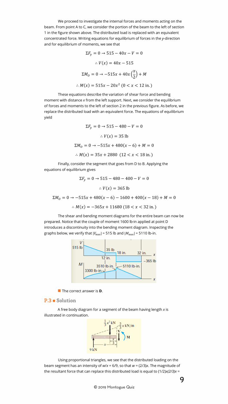
P.2 ■ Solution The reactions are easily determined with a free body diagram.
First, we sum moments relative to point A,
Σ𝑀𝑀𝐴𝐴 = 0 → 𝐵𝐵𝑦𝑦(32)− 400(22)− 480(6) = 0 ∴ 𝐵𝐵𝑦𝑦 = 365 lb
Then, summing forces in the y-direction, we have
Σ𝐹𝐹𝑦𝑦 = 0 → 𝐴𝐴 − 400 − 480 + 365 = 0 ∴ 𝐴𝐴 = 515 lb
and, because Bx is the only force acting on the x-direction, we immediately have 𝐵𝐵𝑥𝑥 = 0.
1 2 3 4 5 6 7m
10
20
30
40
50kNm
9 © 2019 Montogue Quiz
We proceed to investigate the internal forces and moments acting on the beam. From point A to C, we consider the portion of the beam to the left of section 1 in the figure shown above. The distributed load is replaced with an equivalent concentrated force. Writing equations for equilibrium of forces in the y-direction and for equilibrium of moments, we see that
Σ𝐹𝐹𝑦𝑦 = 0 → 515− 40𝑥𝑥 − 𝑉𝑉 = 0
∴ 𝑉𝑉(𝑥𝑥) = 40𝑥𝑥 − 515
Σ𝑀𝑀𝑂𝑂 = 0 → −515𝑥𝑥 + 40𝑥𝑥 �𝑥𝑥2� + 𝑀𝑀
∴ 𝑀𝑀(𝑥𝑥) = 515𝑥𝑥 − 20𝑥𝑥2 (0 < 𝑥𝑥 < 12 in. )
These equations describe the variation of shear force and bending moment with distance x from the left support. Next, we consider the equilibrium of forces and moments to the left of section 2 in the previous figure. As before, we replace the distributed load with an equivalent force. The equations of equilibrium yield
Σ𝐹𝐹𝑦𝑦 = 0 → 515− 480 − 𝑉𝑉 = 0
∴ 𝑉𝑉(𝑥𝑥) = 35 lb
Σ𝑀𝑀𝑂𝑂 = 0 → −515𝑥𝑥 + 480(𝑥𝑥 − 6) + 𝑀𝑀 = 0
∴ 𝑀𝑀(𝑥𝑥) = 35𝑥𝑥 + 2880 (12 < 𝑥𝑥 < 18 in. )
Finally, consider the segment that goes from D to B. Applying the equations of equilibrium gives
Σ𝐹𝐹𝑦𝑦 = 0 → 515 − 480− 400− 𝑉𝑉 = 0
∴ 𝑉𝑉(𝑥𝑥) = 365 lb
Σ𝑀𝑀𝑂𝑂 = 0 → −515𝑥𝑥 + 480(𝑥𝑥 − 6)− 1600 + 400(𝑥𝑥 − 18) + 𝑀𝑀 = 0
∴ 𝑀𝑀(𝑥𝑥) = −365𝑥𝑥 + 11680 (18 < 𝑥𝑥 < 32 in. )
The shear and bending moment diagrams for the entire beam can now be prepared. Notice that the couple of moment 1600 lb∙in applied at point D introduces a discontinuity into the bending moment diagram. Inspecting the graphs below, we verify that |𝑉𝑉max| = 515 lb and |𝑀𝑀max| = 5110 lb-in.
■ The correct answer is D.
P.3 ■ Solution
A free body diagram for a segment of the beam having length x is illustrated in continuation.
Using proportional triangles, we see that the distributed loading on the beam segment has an intensity of w/x = 6/9, so that w = (2/3)x. The magnitude of the resultant force that can replace this distributed load is equal to (1/2)x(2/3)x =

10 © 2019 Montogue Quiz
(1/3)x2. This force acts through the centroid of the distributed loading area, a distance (1/3)x from the right end, as shown in the previous figure. Writing equations for equilibrium of forces in the y-direction and for equilibrium of moments, we see that
Σ𝐹𝐹𝑦𝑦 = 0 → 9 −13𝑥𝑥
2 − 𝑉𝑉 = 0
∴ 𝑉𝑉(𝑥𝑥) = 9 −13𝑥𝑥2
Σ𝑀𝑀𝑂𝑂 = 0 → −9𝑥𝑥 +13 𝑥𝑥
2 �𝑥𝑥3�+ 𝑀𝑀 = 0
∴ 𝑀𝑀(𝑥𝑥) = 9𝑥𝑥 −𝑥𝑥3
9 (0 < 𝑥𝑥 < 9 m)
Plots of shear and bending moment are given below.
Note that the shear force diagrams in options A and C are quite similar. However, they differ in the point of zero shear, which can be easily obtained by setting the equation of V(x) to zero; that is,
𝑉𝑉(𝑥𝑥) = 9 −13𝑥𝑥
2 = 0 →13 𝑥𝑥
2 = 9
∴ 𝑥𝑥 = 271 2⁄ = 5.2 m
Hence, the graph in A is the correct shear force diagram.
■ The correct answer is A.
P.4 ■ Solution
The support reactions are most easily obtained by considering the resultants of the distributed loads on the whole beam. In doing so, the reactions are determined as R1 = 247 lb and R2 = 653 lb.
11 © 2019 Montogue Quiz
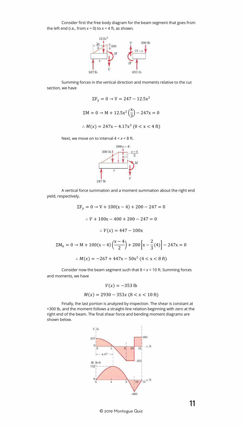
Consider first the free body diagram for the beam segment that goes from the left end (i.e., from x = 0) to x = 4 ft, as shown.
Summing forces in the vertical direction and moments relative to the cut section, we have
ΣFy = 0 → V = 247− 12.5x2
ΣM = 0 → M + 12.5x2 �x3� − 247x = 0
∴ 𝑀𝑀(𝑥𝑥) = 247x− 4.17x3 (0 < x < 4 ft)
Next, we move on to interval 4 < x < 8 ft.
A vertical force summation and a moment summation about the right end yield, respectively,
ΣFy = 0 → V + 100(x− 4) + 200− 247 = 0
∴ 𝑉𝑉 + 100x− 400 + 200− 247 = 0
∴ 𝑉𝑉(𝑥𝑥) = 447− 100x
ΣM0 = 0 → M + 100(x− 4) �x− 4
2 �+ 200 �x −23 (4)� − 247x = 0
∴ 𝑀𝑀(𝑥𝑥) = −267 + 447x− 50x2 (4 < x < 8 ft)
Consider now the beam segment such that 8 < x < 10 ft. Summing forces and moments, we have
𝑉𝑉(𝑥𝑥) = −353 lb
𝑀𝑀(𝑥𝑥) = 2930 − 353𝑥𝑥 (8 < 𝑥𝑥 < 10 ft)
Finally, the last portion is analyzed by inspection. The shear is constant at +300 lb, and the moment follows a straight-line relation beginning with zero at the right end of the beam. The final shear force and bending moment diagrams are shown below.

12 © 2019 Montogue Quiz
After graphing the diagrams, we note that the maximum positive bending moment occurs somewhere in the interval 0 < x < 8 ft, while the maximum negative bending moment is readily seen to be −600 lb∙ft at x = 10 ft. To obtain the maximum positive bending moment, recall that the internal moment is maximum when the shear force equals zero. In segment 0 < x < 8 ft, we have V(x) = 447 – 100x. Setting this to zero, we obtain x = 4.47 m. The bending moment at this position is
𝑀𝑀(4.47) = −267 + 447(4.47)− 50(4.47)2 = 732.0 lb ∙ ft
which is greater in absolute value than 600 lb∙ft; therefore, it is taken as the maximum bending moment acting on the structure.
■ The correct answer is A.
P.5 ■ Solution
We begin with the assertion that the derivative of shear with respect to x equals the distributed load w, while the derivative of bending moment with respect to x yields the shear force. Mathematically,
𝑑𝑑𝑉𝑉𝑑𝑑𝑥𝑥
= −𝑤𝑤 →𝑑𝑑𝑉𝑉𝑑𝑑𝑥𝑥 = −𝑤𝑤0 sin
𝜋𝜋𝑥𝑥𝐿𝐿
∴ 𝑉𝑉(𝑥𝑥) = −�𝑤𝑤0 sin𝜋𝜋𝑥𝑥𝐿𝐿 𝑑𝑑𝑥𝑥 =
𝑤𝑤0𝐿𝐿𝜋𝜋 cos
𝜋𝜋𝑥𝑥𝐿𝐿 + 𝐶𝐶1 =
𝑑𝑑𝑀𝑀𝑑𝑑𝑥𝑥
∴ 𝑀𝑀(𝑥𝑥) =𝑤𝑤0𝐿𝐿2
𝜋𝜋2 sin𝜋𝜋𝑥𝑥𝐿𝐿 + 𝐶𝐶1𝑥𝑥 + 𝐶𝐶2
We have two boundary conditions, namely, M(0) = 0 and M(L) = 0. Applying these gives
𝑀𝑀(0) =𝑤𝑤0𝐿𝐿2
𝜋𝜋2 sin 0 + 𝐶𝐶1(0) + 𝐶𝐶2 = 0 → 𝐶𝐶2 = 0
𝑀𝑀(𝐿𝐿) =𝑤𝑤0𝐿𝐿2
𝜋𝜋2 sin𝜋𝜋�=0
+ 𝐶𝐶1𝐿𝐿 + 𝐶𝐶2⏟=0
= 0 → 𝐶𝐶1 = 0
Thus the expression for shear force is simply
𝑉𝑉(𝑥𝑥) =𝑤𝑤0𝐿𝐿𝜋𝜋
cos𝜋𝜋𝑥𝑥𝐿𝐿
while for bending moment,
𝑀𝑀(𝑥𝑥) =𝑤𝑤0𝐿𝐿2
𝜋𝜋2 sin𝜋𝜋𝑥𝑥𝐿𝐿 (0 < 𝑥𝑥 < 𝐿𝐿)
We set 𝑑𝑑𝑀𝑀 𝑑𝑑𝑥𝑥⁄ = V = 0. Inspecting the equation for V(x), we see that V(L/2) = 0, in which case we have
𝑉𝑉 �𝐿𝐿
2𝜋𝜋� =𝑤𝑤0𝐿𝐿𝜋𝜋 cos �
𝜋𝜋𝐿𝐿 �
𝐿𝐿2�� =
𝑤𝑤0𝐿𝐿𝜋𝜋 cos �
𝜋𝜋2������
=0
= 0
The maximum bending moment is then
𝑀𝑀max = 𝑀𝑀�𝐿𝐿2� =
𝑤𝑤0𝐿𝐿2
𝜋𝜋2 sin �𝜋𝜋𝐿𝐿 �
𝐿𝐿2�� =
𝑤𝑤0𝐿𝐿2
𝜋𝜋2 sin𝜋𝜋2 =
𝑤𝑤0𝐿𝐿2
𝜋𝜋2
■ The correct answer is D.
P.6 ■ Solution
Consider the free body diagram for this structure.
From symmetry, we can infer that Ey = Dy. Further, Ex = Dx = Dy tan𝜃𝜃. Summing forces in the y-direction, we have

13 © 2019 Montogue Quiz
Σ𝐹𝐹𝑦𝑦 = 0 → 𝐷𝐷𝑦𝑦 + 𝐸𝐸𝑦𝑦 − 3 = 0
∴ 𝐷𝐷𝑦𝑦 = 𝐸𝐸𝑦𝑦 = 1.5 kN
From the previous equality, we have Dx = 1.5tan𝜃𝜃 → and Ex = 1.5tan𝜃𝜃 ←. We replace the forces at D and E with equivalent force-couple systems, as illustrated below.
The equivalent moment M0 is such that M0 = 1.5tan𝜃𝜃 × 0.5 = (750 N∙m)tan𝜃𝜃. Note that the weight of the beam per unit length is
𝑤𝑤 =𝑊𝑊𝐿𝐿 =
3 kN5 m = 0.6
kNm = 600
Nm
We are now ready to prepare the shear and bending moment diagrams. First, consider the segment that goes from A to F.
The sum of forces in the y-direction is such that
Σ𝐹𝐹𝑦𝑦 = 0 → −𝑉𝑉 − 600𝑥𝑥 = 0 ∴ 𝑉𝑉(𝑥𝑥) = −600𝑥𝑥
The sum of moments relative to the right end of this segment is
Σ𝑀𝑀0 = 0 → 𝑀𝑀 + 600𝑥𝑥 �𝑥𝑥2� = 0 ∴ 𝑀𝑀(𝑥𝑥) = −300𝑥𝑥2 (0 < 𝑥𝑥 < 1.5 m)
Note that, for x = 0, we have V(0) = 0 and M(0) = 0, while, for x = 1.5 m, it is seen that V(1.5) = −900 N and M(1.5) = −675 N∙m. Next, consider the segment that goes from F to H. The sum of vertical forces and the sum of moments relative to the right end yield, respectively,
Σ𝐹𝐹𝑦𝑦 = 0 → 1500− 600𝑥𝑥 − 𝑉𝑉 = 0
∴ 𝑉𝑉(𝑥𝑥) = 1500 − 600𝑥𝑥
Σ𝑀𝑀0 = 0 → −1500(𝑥𝑥 − 1.5) + 600𝑥𝑥 �𝑥𝑥2�+ 𝑀𝑀−𝑀𝑀0 = 0
∴ −1500𝑥𝑥 + 2250 + 300𝑥𝑥2 −𝑀𝑀0 + 𝑀𝑀 = 0
∴ 𝑀𝑀(𝑥𝑥) = 𝑀𝑀0 − 300𝑥𝑥2 + 1500𝑥𝑥 − 2250 (1.5 < 𝑥𝑥 < 2.5 m) At x = 1.5 m, we have V(1.5) = 600 N and M(1.5) = M0 – 675 N∙m, while, at x = 2.5 m, we note that V(2.5) = 0 and M(2.5) = M0 – 375 N∙m. From G to B, the diagrams can be easily obtained through symmetry. The ensuing shear and bending moment diagrams are as shown.
It is easy to see that the largest shear force is |𝑉𝑉max| = 900 N at x = 1.5 m and 3.5 m. Now, making 𝜃𝜃 = 60o, moment M0 becomes M0 = 750× tan 60o = 1299 N∙m. Hence, we have, just to the right of point F, M(1.5) = M0 – 675 = 1299 – 675 =

14 © 2019 Montogue Quiz
624 N∙m, while, just to the right of point G, we have M(2.5) = M0 – 375 = 1299 – 375 = 924 N∙m. Accordingly,|Mmax| = 924 N∙m.
■ The correct answer is D.
P.7 ■ Solution
Consider the following free body diagram for the beam segment that extends itself from the left end to the right of point B.
Taking moments about point B in the beam, we have
Σ𝑀𝑀𝐵𝐵 = 0 →12
(2𝑎𝑎 + 𝑏𝑏) × 𝑤𝑤 �13
(𝑏𝑏 − 𝑎𝑎)� − 𝐴𝐴𝑦𝑦𝑏𝑏 = 0
∴ 𝐴𝐴𝑦𝑦 =𝑤𝑤2𝑏𝑏 (2𝑎𝑎 + 𝑏𝑏)(𝑏𝑏 − 𝑎𝑎)
Consider now the following free body diagram.
The problem requires that VC = 0. Summing forces in the vertical direction, then, we have
Σ𝐹𝐹𝑦𝑦 = 0 →𝑤𝑤6𝑏𝑏
(2𝑎𝑎 + 𝑏𝑏)(𝑏𝑏 − 𝑎𝑎) −12�𝑎𝑎 +
𝑏𝑏2�𝑤𝑤2 = 0
∴𝑤𝑤6𝑏𝑏
(2𝑎𝑎 + 𝑏𝑏)(𝑏𝑏 − 𝑎𝑎) =𝑤𝑤8
(2𝑎𝑎 + 𝑏𝑏)
∴𝑎𝑎𝑏𝑏
=14
■ The correct answer is C.
P.8 ■ Solution
Consider first the free body diagram for member AB.
The vertical component of the reaction at B can be obtained by taking moments about point A; that is,
Σ𝑀𝑀𝐵𝐵 = 0 → 𝐵𝐵𝑦𝑦 × 4 − 1000 × 2 = 0 ∴ 𝐵𝐵𝑦𝑦 = 500 N
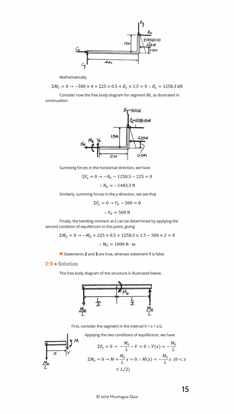
Similarly, the horizontal component of B can be obtained by taking moments about point C, as shown.
15 © 2019 Montogue Quiz
Mathematically,
Σ𝑀𝑀𝐶𝐶 = 0 → −500 × 4 + 225 × 0.5 + 𝐵𝐵𝑥𝑥 × 1.5 = 0 ∴ 𝐵𝐵𝑥𝑥 = 1258.3 kN
Consider now the free body diagram for segment BE, as illustrated in continuation.
Summing forces in the horizontal direction, we have
Σ𝐹𝐹𝑥𝑥 = 0 → −𝑁𝑁𝐸𝐸 − 1258.3− 225 = 0
∴ 𝑁𝑁𝐸𝐸 = −1483.3 N
Similarly, summing forces in the y-direction, we see that
Σ𝐹𝐹𝑦𝑦 = 0 → 𝑉𝑉𝐸𝐸 − 500 = 0
∴ 𝑉𝑉𝐸𝐸 = 500 N
Finally, the bending moment at E can be determined by applying the second condition of equilibrium to this point, giving
Σ𝑀𝑀𝐸𝐸 = 0 → −𝑀𝑀𝐸𝐸 + 225 × 0.5 + 1258.3 × 1.5 − 500 × 2 = 0
∴ 𝑀𝑀𝐸𝐸 = 1000 N ∙ m
■ Statements 2 and 3 are true, whereas statement 1 is false.
P.9 ■ Solution
The free body diagram of the structure is illustrated below.
First, consider the segment in the interval 0 < x < L/2.
Applying the two conditions of equilibrium, we have
Σ𝐹𝐹𝑦𝑦 = 0 → −𝑀𝑀0
𝐿𝐿 − 𝑉𝑉 = 0 ∴ 𝑉𝑉(𝑥𝑥) = −𝑀𝑀0
𝐿𝐿
Σ𝑀𝑀0 = 0 → 𝑀𝑀 +𝑀𝑀0
𝐿𝐿 𝑥𝑥 = 0 ∴ 𝑀𝑀(𝑥𝑥) = −𝑀𝑀0
𝐿𝐿 𝑥𝑥 (0 < 𝑥𝑥
< 𝐿𝐿 2⁄ )

16 © 2019 Montogue Quiz
Next, consider the segment located in the interval L/2 < x < L. Applying the two conditions of equilibrium, we see that
Σ𝐹𝐹𝑦𝑦 = 0 → −𝑀𝑀0𝐿𝐿− 𝑉𝑉 = 0 ∴ 𝑉𝑉(𝑥𝑥) = −𝑀𝑀0
𝐿𝐿
Σ𝑀𝑀0 = 0 → 𝑀𝑀 +𝑀𝑀0
𝐿𝐿 𝑥𝑥 −𝑀𝑀0 = 0 ∴ 𝑀𝑀(𝑥𝑥)
= 𝑀𝑀0 −𝑀𝑀0
𝐿𝐿 𝑥𝑥
= 𝑀𝑀0 �1 −𝑥𝑥𝐿𝐿� �
𝐿𝐿2 < 𝑥𝑥 < 𝐿𝐿�
When M0 = 500 N∙m and L = 9 m, and noting that Vmax = 5 kN and Mmax = 22 kN∙m, we make use of the expressions
𝑉𝑉max =𝑀𝑀0
𝐿𝐿 → 5 =𝑀𝑀0
9
∴ 𝑀𝑀0 = 45 kN ∙ m
and
𝑀𝑀max =𝑀𝑀0
2 → 22 =𝑀𝑀0
2
∴ 𝑀𝑀0 = 44 kN ∙ m
The lower result controls; thus, the largest couple moment that the beam is capable of withstanding is M0 = 44 kN∙m.
■ The correct answer is B.
P.10 ■ Solution
Since the loading is discontinuous at the midspan, the shear and moment equations must be written for regions 0 < x < 6 ft and 6 < x < 12 ft of the beam. The free-body diagrams of the beam’s segment sectioned through the arbitrary point within these two regions are shown in figures (b) and (c) below. The reactions at A and B were found as Ay = 7.5w0 and By = 10.5w0.
Consider first the segment for which 0 < x < 6 ft. Summing forces in the vertical direction and moments, we obtain
Σ𝐹𝐹𝑦𝑦 = 0 → 7.5𝑤𝑤0 − 𝑤𝑤0𝑥𝑥 − 𝑉𝑉 = 0
∴ 𝑉𝑉(𝑥𝑥) = 𝑤𝑤0(7.5 − 𝑥𝑥) (I)
Σ𝑀𝑀0 = 0 → 𝑤𝑤0𝑥𝑥 �𝑥𝑥2� − 7.5𝑤𝑤0𝑥𝑥 + 𝑀𝑀 = 0
∴ 𝑀𝑀(𝑥𝑥) = 7.5𝑤𝑤0𝑥𝑥 − 0.5𝑤𝑤0𝑥𝑥2 =𝑤𝑤02
(15𝑥𝑥 − 𝑥𝑥2) (0 < 𝑥𝑥 < 6 ft) (II)
Next, consider the segment that encompasses 6 < x < 12 ft. Summing forces and moments as before, we see that

17 © 2019 Montogue Quiz
Σ𝐹𝐹𝑦𝑦 = 0 → 10.5𝑤𝑤0 − 2𝑤𝑤0(12 − 𝑥𝑥) + 𝑉𝑉 = 0 ∴ 𝑉𝑉(𝑥𝑥)= 2𝑤𝑤0(12 − 𝑥𝑥)− 10.5𝑤𝑤0 = 24𝑤𝑤0 − 2𝑤𝑤0𝑥𝑥 − 10.5𝑤𝑤0= 𝑤𝑤0(13.5− 2𝑥𝑥) (III)
Σ𝑀𝑀0 = 0 → 10.5𝑤𝑤0(12− 𝑥𝑥)− 2𝑤𝑤0(12 − 𝑥𝑥) �12
(12− 𝑥𝑥)� − 𝑀𝑀 = 0
∴ 𝑀𝑀(𝑥𝑥) = 𝑤𝑤0(−𝑥𝑥2 + 13.5𝑥𝑥 − 18) (6 < 𝑥𝑥 < 12 ft) (IV)
The shear diagram is plotted using Equations (I) and (III). The value of the shear force at x = 6 ft can be evaluated using either equation,
𝑉𝑉(6) = 𝑤𝑤0(7.5− 6) = 1.5𝑤𝑤0
The location at which the shear is equal to zero is obtained by setting V = 0 in Equation (III),
𝑤𝑤0(13.5− 2𝑥𝑥) = 0
∴ 13.5𝑤𝑤0 − 2𝑤𝑤0𝑥𝑥 = 0
∴ 𝑥𝑥 =13.5
2 = 6.75 ft
The moment diagram in the figure below is plotted using Equations (II) and (IV).
The value of the moment at x = 6 ft is evaluated as
𝑀𝑀(6) =𝑤𝑤02 (15 × 6 − 62) = 27𝑤𝑤0
The value of the moment at x = 6.75 ft is evaluated using Equation (IV),
𝑀𝑀(6.75) = 𝑤𝑤0(−6.752 + 13.5 × 6.75− 18) = 27.56𝑤𝑤0
By observing the shear and moment diagrams, we verify that Vmax = 10.5w0 and Mmax = 27.56w0. We can then propose two equalities,
𝑉𝑉max = 10.5𝑤𝑤0 = 1200
∴ 𝑤𝑤0 = 114.3 lb ∙ ft−1
and 𝑀𝑀max = 27.56𝑤𝑤0 = 600
∴ 𝑤𝑤0 =600
27.56 = 21.8 lb ∙ ft−1
The second result governs, and the largest intensity of the distributed load is taken as w0 = 21.8 lb/ft.
■ The correct answer is B.

18 © 2019 Montogue Quiz
P.11 ■ Solution Consider segment CB, as shown.
The sum of moments relative to point C (the left end of the cut off segment) must equal zero; that is,
Σ𝑀𝑀𝐶𝐶 = 0 → −𝑀𝑀 + 2.2 × 3 × 103 × 1.1 = 0
∴ 𝑀𝑀 = 7.26 kN
Next, we compute the section modulus for the rectangular section, which is given by
𝑆𝑆 =𝑏𝑏ℎ2
6 =100 × 2002
6 = 6.67 × 105 mm3 = 6.67 × 10⁻⁴ m3
Finally, the normal stress can be obtained as the ratio of moment to section modulus (i.e., the flexure formula),
𝜎𝜎 =𝑀𝑀𝑆𝑆 =
72606.67 × 10−4 = 1.088 × 10⁷ Pa = 10.9 MPa
■ The correct answer is A.
P.12 ■ Solution As in Problem 11, the cross-section of the beam is rectangular, and its
section modulus equals
𝑆𝑆 =𝑏𝑏ℎ2
6=
24 × 602
6= 14,400 mm3 = 1.44 × 10⁻⁵ m3
Using the flexure formula, we can write 𝜎𝜎 = 𝑀𝑀 𝑆𝑆⁄ , so that 𝑀𝑀 = 𝑆𝑆𝜎𝜎. At point D, we have 𝑀𝑀𝐷𝐷 = 1.44 × 10⁻⁵(55 × 106) = 792 N ∙ m, while at point F we have 𝑀𝑀𝐹𝐹 =1.44 × 10⁻⁵(37.5 × 10⁶) = 540 N ∙ m. Now, consider segment FB of the beam.
The sum of moments relative to point F must equal zero. Hence,
Σ𝑀𝑀𝐹𝐹 = 0 → −540 + 0.3𝐵𝐵 = 0 ∴ 𝐵𝐵 =5400.3
= 1800 N
Next, using free body DEFB, we have the sum of moments
Σ𝑀𝑀𝐷𝐷 = 0 → −792 − 0.3𝑄𝑄 +0.8(1800) = 0
∴ 𝑄𝑄 =(−792 + 0.8 × 1800)
0.3= 2160 N
Then, consider the beam as a whole.
Σ𝑀𝑀𝐴𝐴 = 0 → −0.2𝑃𝑃 − 0.7 × 2160 + 1.2× 1800 = 0
𝑃𝑃 =−0.7 × 2160 + 1.2 × 1800
0.2= 3240 N
Summing forces in the y-direction, we obtain the value of reaction A,
Σ𝐹𝐹𝑦𝑦 = 0 → 𝐴𝐴− 3240− 2160 + 1800 = 0 ∴ 𝐴𝐴 = 3600 N
We are now ready to consider the shear diagram and its areas, from which the moments can be determined.

19 © 2019 Montogue Quiz
From A to C- (just to the left of C), 𝑉𝑉(𝑥𝑥) = 3600 N and 𝐴𝐴𝐴𝐴𝐶𝐶 = 0.2(3600) =720 N ∙ m = 𝑀𝑀; from C+ (just to the right of C) to E-, we have 𝑉𝑉(𝑥𝑥) = 3600− 3240 =360 N and 𝐴𝐴𝐶𝐶𝐸𝐸 = 0.5(360) = 180 N ∙ m = 𝑀𝑀; finally, from E+ to B, it follows that 𝑉𝑉(𝑥𝑥) = 360− 2160 = −1800 N and 𝐴𝐴EB = 0.5(−1800) = −900 N ∙ m. Now, the bending moments are found to be 𝑀𝑀𝐴𝐴 = 0,𝑀𝑀𝐶𝐶 = 0 + 720 = 720 N ∙m, 𝑀𝑀𝐸𝐸 = 720 +180 = 900 N ∙m, and 𝑀𝑀𝐵𝐵 = 900− 900 = 0. Clearly, the maximum bending moment is |𝑀𝑀max| = 900 N ∙m at point E. The maximum normal stress follows from the flexure formula,
𝜎𝜎max =|𝑀𝑀max|𝑆𝑆 =
9001.44 × 10−5 = 62.5 MPa
■ The correct answer is C.
Answer Summary
Problem 1 B Problem 2 D Problem 3 A Problem 4 A Problem 5 D Problem 6 D Problem 7 C Problem 8 T/F Problem 9 B
Problem 10 B Problem 11 A Problem 12 C
References BEER, F., JOHNSTON, E., DEWOLF, J. and MAZUREK, D. (2015). Mechanics of
Materials. 7th edition. New York: McGraw-Hill. BEER, F., JOHNSTON, E., MAZUREK, D. and CORNWELL, P. (2013). Vector
Mechanics for Engineers: Statics. 10th edition. New York: McGraw-Hill. HIBBELER, R. (2013). Engineering Mechanics: Statics. 13th edition. Upper
Saddle River: Pearson. MERIAM, J. and KRAIGE, L. (2002). Engineering Mechanics: Statics. 5th
edition. Hoboken: John Wiley and Sons.
Got any questions related to this quiz? We can help! Send a message to [email protected] and we’ll
answer your question as soon as possible.