Interferometer based on strongly coupled multi-core optical fiber for ... · 1Department of...
7
Interferometer based on strongly coupled multi-core optical fiber for accurate vibration sensing JOEL VILLATORO, 1,2,* ENRIQUE ANTONIO-LOPEZ, 3 JOSEBA ZUBIA, 1 AXEL SCHÜLZGEN, 3 AND RODRIGO AMEZCUA-CORREA 3 1 Department of Communications Engineering, Escuela de Ingeniería de Bilbao, University of the Basque Country (UPV/EHU), Alda. Urquijo s/n, E-48013, Bilbao, Spain 2 IKERBASQUE—Basque Foundation for Science, E-48011 Bilbao, Spain 3 CREOL, The College of Optics & Photonics, University of Central Florida, P.O. Box 162700, Orlando, Florida 32816-2700, USA *[email protected] Abstract: We report on the use of a simple interferometer built with strongly-coupled core optical fiber for accurate vibration sensing. Our multi-core fiber (MCF) is designed to mode match a standard single-mode optical fiber (SMF). The interferometer consists of a low insertion loss SMF-MCF-SMF structure where only two super-modes interfere. The polymer coating of the MCF was structured and the interferometer was sandwiched between a flat piece and a V-groove. In this manner our device is highly sensitive to force with sensitivity reaching −4225 pm/N. To make the MCF interferometer sensitive to vibrations the flat piece was allowed to move, thus, its periodic movements exert cyclic localized pressure on the MCF which makes the interference pattern to shift periodically. Our sensors can be used to monitor vibrations in a broad frequency range with the advantage that the measurements are unaffected by temperature changes. © 2017 Optical Society of America OCIS codes: (060.2370) Fiber optics sensors; (060.4005) Microstructured fibers; (280.4788) Optical sensing and sensors. References and links 1. T. K. Gangopadhyay, “Prospects for fiber Bragg gratings and Fabry-Perot interferometers in fiber-optic vibration sensing,” Sensor Actuat. A-Phys. 113, 20–38 (2004). 2. Y. R. García, J. M. Corres, and J. Goicoechea, “Vibration detection using optical fiber sensors,” J. Sens. 2010, 936487 (2010). 3. T. A. Berkoff and A. D. Kersey, “Experimental demonstration of a fiber Bragg grating accelerometer,” IEEE Photonics Technol. Lett. 8(12), 1677–1679 (1996). 4. M. D. Todd, G. A. Johnson, B. A. Althouse, and S. T. Vohra, “Flexural beam-based fiber Bragg grating accelerometers,” IEEE Photonics Technol. Lett. 10(11), 1605–1607 (1998). 5. A. Fender, W. N. MacPherson, R. R. Maier, J. S. Barton, D. S. George, R. I. Howden, and R. Suo, “Two-axis temperature-insensitive accelerometer based on multicore fiber Bragg gratings,” IEEE Sens. J. 8(7), 1292–1298 (2008). 6. P. F. da Costa Antunes, H. F. T. Lima, N. J. Alberto, H. Rodrigues, P. M. F. Pinto, J. de Lemos Pinto, R. N. Nogueira, H. Varum, A. G. Costa, and P. S. de Brito Andre, “Optical fiber accelerometer system for structural dynamic monitoring,” IEEE Sens. J. 9(11), 1347–1354 (2009). 7. Q. Liu, Z. A. Jia, H. Fu, D. Yu, H. Gao, and X. Qiao, “Double cantilever beams accelerometer using short fiber Bragg grating for eliminating chirp,” IEEE Sens. J. 16(17), 6611–6616 (2016). 8. R. P. Linessio, K. de Morais Sousa, T. da Silva, C. A. Bavastri, P. F. da Costa Antunes, and J. C. C. da Silva, “Induction motors vibration monitoring using a biaxial optical fiber accelerometer,” IEEE Sens. J. 16(22), 8075– 8082 (2016). 9. B. Dong, B. Zhang, J. Ng, Y. Wang, and C. Yu, “Ultrahigh-sensitivity fiber acoustic sensor with a dual cladding modes fiber up-taper interferometer,” IEEE Photonics Technol. Lett. 27(21), 2234–2237 (2011). 10. B. Xu, Y. Li, M. Sun, Z. W. Zhang, X. Y. Dong, Z. X. Zhang, and S. Z. Jin, “Acoustic vibration sensor based on nonadiabatic tapered fibers,” Opt. Lett. 37(22), 4768–4770 (2012). 11. X. Wu, X. Wang, S. Li, S. Huang, Q. Ge, and B. Yu, “Cantilever fiber-optic accelerometer based on modal interferometer,” IEEE Photonics Technol. Lett. 27(15), 1632–1635 (2015). Vol. 25, No. 21 | 16 Oct 2017 | OPTICS EXPRESS 25734 #297062 https://doi.org/10.1364/OE.25.025733 Journal © 2017 Received 31 May 2017; revised 11 Jul 2017; accepted 13 Jul 2017; published 9 Oct 2017
Transcript of Interferometer based on strongly coupled multi-core optical fiber for ... · 1Department of...
Interferometer based on strongly coupled multi-core optical fiber for accurate vibration sensing
JOEL VILLATORO,1,2,* ENRIQUE ANTONIO-LOPEZ,3 JOSEBA ZUBIA,1 AXEL SCHÜLZGEN,3 AND RODRIGO AMEZCUA-CORREA
3 1Department of Communications Engineering, Escuela de Ingeniería de Bilbao, University of the Basque Country (UPV/EHU), Alda. Urquijo s/n, E-48013, Bilbao, Spain 2IKERBASQUE—Basque Foundation for Science, E-48011 Bilbao, Spain 3CREOL, The College of Optics & Photonics, University of Central Florida, P.O. Box 162700, Orlando, Florida 32816-2700, USA *[email protected]
Abstract: We report on the use of a simple interferometer built with strongly-coupled core optical fiber for accurate vibration sensing. Our multi-core fiber (MCF) is designed to mode match a standard single-mode optical fiber (SMF). The interferometer consists of a low insertion loss SMF-MCF-SMF structure where only two super-modes interfere. The polymer coating of the MCF was structured and the interferometer was sandwiched between a flat piece and a V-groove. In this manner our device is highly sensitive to force with sensitivity reaching −4225 pm/N. To make the MCF interferometer sensitive to vibrations the flat piece was allowed to move, thus, its periodic movements exert cyclic localized pressure on the MCF which makes the interference pattern to shift periodically. Our sensors can be used to monitor vibrations in a broad frequency range with the advantage that the measurements are unaffected by temperature changes. © 2017 Optical Society of America
OCIS codes: (060.2370) Fiber optics sensors; (060.4005) Microstructured fibers; (280.4788) Optical sensing and sensors.
References and links
1. T. K. Gangopadhyay, “Prospects for fiber Bragg gratings and Fabry-Perot interferometers in fiber-optic vibration sensing,” Sensor Actuat. A-Phys. 113, 20–38 (2004).
2. Y. R. García, J. M. Corres, and J. Goicoechea, “Vibration detection using optical fiber sensors,” J. Sens. 2010, 936487 (2010).
3. T. A. Berkoff and A. D. Kersey, “Experimental demonstration of a fiber Bragg grating accelerometer,” IEEE Photonics Technol. Lett. 8(12), 1677–1679 (1996).
4. M. D. Todd, G. A. Johnson, B. A. Althouse, and S. T. Vohra, “Flexural beam-based fiber Bragg grating accelerometers,” IEEE Photonics Technol. Lett. 10(11), 1605–1607 (1998).
5. A. Fender, W. N. MacPherson, R. R. Maier, J. S. Barton, D. S. George, R. I. Howden, and R. Suo, “Two-axis temperature-insensitive accelerometer based on multicore fiber Bragg gratings,” IEEE Sens. J. 8(7), 1292–1298 (2008).
6. P. F. da Costa Antunes, H. F. T. Lima, N. J. Alberto, H. Rodrigues, P. M. F. Pinto, J. de Lemos Pinto, R. N. Nogueira, H. Varum, A. G. Costa, and P. S. de Brito Andre, “Optical fiber accelerometer system for structural dynamic monitoring,” IEEE Sens. J. 9(11), 1347–1354 (2009).
7. Q. Liu, Z. A. Jia, H. Fu, D. Yu, H. Gao, and X. Qiao, “Double cantilever beams accelerometer using short fiber Bragg grating for eliminating chirp,” IEEE Sens. J. 16(17), 6611–6616 (2016).
8. R. P. Linessio, K. de Morais Sousa, T. da Silva, C. A. Bavastri, P. F. da Costa Antunes, and J. C. C. da Silva, “Induction motors vibration monitoring using a biaxial optical fiber accelerometer,” IEEE Sens. J. 16(22), 8075–8082 (2016).
9. B. Dong, B. Zhang, J. Ng, Y. Wang, and C. Yu, “Ultrahigh-sensitivity fiber acoustic sensor with a dual cladding modes fiber up-taper interferometer,” IEEE Photonics Technol. Lett. 27(21), 2234–2237 (2011).
10. B. Xu, Y. Li, M. Sun, Z. W. Zhang, X. Y. Dong, Z. X. Zhang, and S. Z. Jin, “Acoustic vibration sensor based on nonadiabatic tapered fibers,” Opt. Lett. 37(22), 4768–4770 (2012).
11. X. Wu, X. Wang, S. Li, S. Huang, Q. Ge, and B. Yu, “Cantilever fiber-optic accelerometer based on modal interferometer,” IEEE Photonics Technol. Lett. 27(15), 1632–1635 (2015).
Vol. 25, No. 21 | 16 Oct 2017 | OPTICS EXPRESS 25734
#297062 https://doi.org/10.1364/OE.25.025733 Journal © 2017 Received 31 May 2017; revised 11 Jul 2017; accepted 13 Jul 2017; published 9 Oct 2017
12. D. Pawar, C. N. Rao, R. K. Choubey, and S. N. Kale, “Mach-Zehnder interferometric photonic crystal fiber for low acoustic frequency detections,” Appl. Phys. Lett. 108(4), 041912 (2016).
13. K. Park, Y. S. Kim, S. Jo, and Y. W. Lee, “Polarization-interference-based fiber vibration sensor incorporating polarization-diversity loop structure,” IEEE Sens. J. 16(7), 1949–1955 (2016).
14. T. K. Gangopadhyay, “Non-contact vibration measurement based on an extrinsic Fabry–Perot interferometer implemented using arrays of single mode fibers,” Meas. Sci. Technol. 15(5), 911–917 (2004).
15. Z. Wang, W. Zhang, J. Han, W. Huang, and F. Li, “Diaphragm-based fiber optic Fabry–Perot accelerometer with high consistency,” J. Lightwave Technol. 32, 4208–4213 (2014).
16. J. Guo and C. Yang, “Non-contact fiber vibration sensor based on intracavity modulation of an extrinsic Fabry–Perot interferometer,” IEEE Sens. J. 15(12), 7229–7233 (2015).
17. J. E. Antonio-Lopez, Z. S. Eznaveh, P. LiKamWa, A. Schülzgen, and R. Amezcua-Correa, “Multicore fiber sensor for high-temperature applications up to 1000°C,” Opt. Lett. 39(15), 4309–4312 (2014).
18. G. Salceda-Delgado, A. Van Newkirk, J. E. Antonio-Lopez, A. Martinez-Rios, A. Schülzgen, and R. Amezcua Correa, “Compact fiber-optic curvature sensor based on super-mode interference in a seven-core fiber,” Opt. Lett. 40(7), 1468–1471 (2015).
19. J. Villatoro, A. Van Newkirk, E. Antonio-Lopez, J. Zubia, A. Schülzgen, and R. Amezcua-Correa, “Ultrasensitive vector bending sensor based on multicore optical fiber,” Opt. Lett. 41(4), 832–835 (2016).
20. J. Villatoro, O. Arrizabalaga, G. Durana, I. Sáez de Ocáriz, E. Antonio-Lopez, J. Zubia, A. Schülzgen, and R. Amezcua-Correa, “Accurate strain sensing based on super-mode interference in strongly coupled multi-core optical fibres,” Sci. Rep. 7(1), 4451 (2017).
21. C. Xia, N. Bai, I. Ozdur, X. Zhou, and G. Li, “Supermodes for optical transmission,” Opt. Express 19(17), 16653–16664 (2011).
22. C. Xia, M. A. Eftekhar, R. Amezcua-Correa, J. E. Antonio-Lopez, A. Schülzgen, D. Christodoulides, and G. Li, “Supermodes in coupled multi-core waveguide structures,” IEEE J. Sel. Top. Quantum Electron. 22(2), 196–207 (2016).
23. A. Sánchez, S. Orozco, A. V. Porta, and M. A. Ortiz, “Elasto–optical behavior model of a step-index fiber under localized pressure,” Mater. Chem. Phys. 139(1), 176–180 (2013).
24. A. Bichler, S. Lecler, B. Serio, S. Fischer, and P. Pfeiffer, “Mode couplings and elasto-optic effects study in a proposed mechanical microperturbed multimode optical fiber sensor,” J. Opt. Soc. Am. A 29(11), 2386–2393 (2012).
25. K. Misiakos, I. Raptis, A. Salapatas, E. Makarona, A. Botsialas, M. Hoekman, R. Stoffer, and G. Jobst, “Broad-band Mach-Zehnder interferometers as high performance refractive index sensors: theory and monolithic implementation,” Opt. Express 22(8), 8856–8870 (2014).
26. J. Villatoro, E. Antonio-Lopez, A. Schülzgen, and R. Amezcua-Correa, “Miniature multicore optical fiber vibration sensor,” Opt. Lett. 42(10), 2022–2025 (2017).
1. Introduction
The monitoring of vibrations is crucial in a number of industrial and scientific applications. Through vibrations analysis one can study or analyze, for instance, seismic events, or the structural health of machines and critical civil infrastructures such as buildings, towers, bridges, etc. The frequency range, vibration amplitude, and environmental conditions differ from one application to another. For example, the detection of seismic waves (produced by earthquakes or volcano eruptions) requires vibrations sensors that can respond to low frequencies (below a few tens of Hz) while the detection of vibration in industrial machines require sensors that can respond to medium or high frequencies (from a few hundred Hz to several kHz). For these reasons there exist a great variety of vibration sensors (also called accelerometers).
Monitoring vibrations with optical fibers has several important advantages, as for example, immunity to electromagnetic interference and corrosion, long distance interrogation, and flexibility, amongst others. All these advantages have promoted the development of fiber optic vibration sensors which have reached a high readiness level [1,2]. Currently, there are two main approaches to sense vibrations with optical fibers [1,2]. One of them is a contact method and involves a test mass that moves with vibration and induces strain to an optical fiber. The other approach is a contactless method and consists of monitoring changes of a small gap between the tip of an optical fiber and a vibrating object. In the first approach, vibrations cause periodic strain to the optical fiber which can be monitored with high resolution, for example, with fiber Bragg gratings (FBG) [1–8] or with different types of interferometers [9–13]. In the second approach, vibrations cause cyclic changes in the gap which can be monitored by means of Fabry-Perot interferometry (FPI) [14–16]. In spite of
Vol. 25, No. 21 | 16 Oct 2017 | OPTICS EXPRESS 25735

their advantages, FBG-, interferometer-, and FPI-based vibration sensors have some drawbacks. Due to the need of a test mass much heavier than the optical fiber, FBG and
Fig. 1. (a) Micrograph of the cross section of the MCF used to build the devices. (b) Drawing of an MCF interferometer showing the two coated regions. Lf is the length of the MCF. (c) Illustration of the MCF interferometer placed on a V-groove. (d) Illustration of the coated zone of the interferometer with the forces that act on the MCF. F0 is the force on the MCF caused vibrations or acoustic waves and F1 and F2 are the reaction forces. (e) Simulated 2D mode profiles of the two super-modes excited in MCF shown in Fig. 1(a).
interferometric vibration sensors tend to be bulky. Moreover, these sensors typically operate well below their fundamental resonance frequency which is determined primarily by the test mass. In addition, the instrumentation to interrogate FBG sensors is usually expensive as picometre-resolution spectrometers are required. The disadvantage of contactless vibrations sensors is their critical alignment between the fiber tip and the vibrating object and the limited distance they can monitor.
Here, we report an approach to build simple, hence cost-effective, vibration (and acoustic) sensors based on a strongly coupled multi-core fiber (MCF). The MCF comprises seven cores embedded in a pure silica cladding [17–20]. To fabricate interferometric vibration sensors, a short segment of the MCF is inserted into conventional single-mode optical fiber (SMF) via the well-established fusion splicing process. The insertion loss is on the order of 0.1 dB [17–20]. The MCF segment has structured coating and is packaged with a piece than has a V-groove. In our design, vibration or acoustic waves cause local periodic pressure to the MCF which causes cyclic changes to the interfering super-modes, and consequently, periodic shift to the interference pattern. To interrogate our sensors, a broadband light source, a miniature spectrometer, and widely available and affordable telecommunications fiber components are necessary. We demonstrate that our sensors can be used to monitor vibrations from 2 to 2500 Hz. They are not affected by abrupt temperature changes. Thus, we believe that the devices here proposed are suitable for a variety of practical applications.
2. Sensor design and operation principle
The strongly-coupled cores MCF used to fabricate our sensors consists of seven identical cores made of germanium doped silica; one core is located in the center of the fiber and the other cores surround the central core. Such an MCF is designed to operate between 1250 to 1650 nm. Figure 1(a) shows a micrograph of the MCF cross section. The size of each core is 9.2 μm, the separation between adjacent cores is 11 μm and the external diameter of our MCF is ca 140 μm. The numerical aperture (NA) at 1550 nm of each of the cores of the MCF is 0.14, i.e., the same NA of telecommunications SMF. Therefore, the coupling between SMF
Vol. 25, No. 21 | 16 Oct 2017 | OPTICS EXPRESS 25736

and MCF is maximized which in turn leads to sensors with minimal insertion loss. The fabrication of the MCF was carried out at the facilities of the University of Central Florida (Orlando, USA).
To make an interferometer, a few centimeters of MCF are fusion spliced to standard telecommunications optical fiber [17–20]. The fabrication of the SMF-MCF-SMF structure; see Fig. 1(b), involves only conventional, well-established cleaving and splicing processes. The MCF preparation (striping and cleaning), cleaving and splicing are carried out with hardware widely used in the telecommunications industry. The junction between the SMF and the MCF can be produced with a conventional or with a specialty fusion splicer. In our case, we used a Fujikura FSM-100P + . The default programs for splicing multimode fibers were used. Under these conditions, the splicer uses a cladding alignment method for which the core of the SMF and the central core of the MCF get precisely aligned, and the SMF and MCF are permanently joined together. In general, the SMF-MCF junctions have high tensile strength and the splicing process takes a few seconds. To make the device to operate in reflection mode we used a commercial single mode retro-reflector (P5-SMF28ER-P01-1 from Thorlabs, Munich, Germany).
Immediately after the splicing, the polymer coating of the MCF was removed; except for two regions, each with a length of approximately 4 mm. The separation between the coated regions was 5 mm. It is important to point out that the length of the coated regions and their separations were found empirically. To achieve the structure shown in Fig. 1(b) we first immersed the MCF in ethanol, approximately during 40 s, and then we removed the undesired coating with an optical fiber stripper. Figures 1(b) and (c) illustrate the final geometry of our device. After coating removal, the MCF interferometer was placed into a precision V-groove (HFV001 from Thorlabs, Munich, Germany) and it was covered with a 2 mm-thick flat plastic piece whose weight was ca 5 g, see Fig. 1(c). The latter was allowed to move under the presence of vibrations or acoustic waves. Figure 1(d) shows an illustration of the MCF resting on the V-groove and covered with a flat piece. It should be noted that in a practical situation the sensor packaging may include springs or similar elements as shown in Fig. 1(d).
To fully understand the operating principle of our devices, first, we will discuss the role of the MCF as its optical properties will determine the sensors’ performance. The guided modes of a coupled-cores MCF are called super-modes [21, 22] as they can be considered as the superposition of isolated LP modes supported by each core. The design of the MCF; which includes the cores’ refractive indices and diameters, the number of cores and their separation, will determine the number and type of super-modes that the MCF can support. However, the excitation conditions will determine the super-modes that can be excited in the MCF. In our case, the MCF is excited with the fundamental mode of an SMF (or LP01). This combined with the axial symmetry of the SMF-MCF-SMF structure and the symmetry of the MCF result in exclusive excitation of only two circularly symmetric super-modes with non-zero intensity in the central core of the MCF. The profiles of such super-modes are shown in Fig. 1(e). To simulate them, we used commercial simulation software (FimmWave by PhotonDesign, Oxford, UK). For the simulations, the core arrangement and dimensions shown in Fig. 1(e) were considered.
It is important to point out that if more than one mode is excited in a waveguide, interference between them will occur. The super-modes excited in our MCF have different propagation constants which can be termed as β1 and β2. Thus, the accumulated phase difference when they pass twice Lf, or the length of MCF, is Δφ = 2(β1 - β2)Lf. The reflection spectrum of our device, like of any other two-beam interferometer, will be proportional to cos(Δφ). Therefore, the reflection of our MCF interferometer will be maximum at certain wavelengths and minimum at others.
Now, if the MCF interferometer is exposed to vibrations or acoustic waves, the flat piece of mass m that covers the MCF will sense a time-varying inertial force, F0 = ma, where a is
Vol. 25, No. 21 | 16 Oct 2017 | OPTICS EXPRESS 25737
acceleration. As m ≈5 g, the force F0 ≈0.049 N will exert a small periodic localized pressure at the coated regions of the MCF since the bare sections of the fiber do not experience such
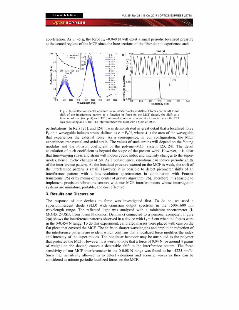
Fig. 2. (a) Reflection spectra observed in an interferometer at different forces on the MCF and shift of the interference pattern as a function of force on the MCF (inset). (b) Shift as a function of time (top plot) and FFT (bottom plot) observed in an interferometer when the PZT was oscillating at 310 Hz. The interferometer was built with a 5 cm of MCF.
perturbations. In Refs [23]. and [24] it was demonstrated in great detail that a localized force F0 on a waveguide induces stress, defined as σ = F0/A, where A is the area of the waveguide that experiences the external force. As a consequence, in our configuration, the MCF experiences transversal and axial strain. The values of such strains will depend on the Young modulus and the Poisson coefficient of the polymer-MCF system [23, 24]. The detail calculation of such coefficient is beyond the scope of the present work. However, it is clear that time-varying stress and strain will induce cyclic index and intensity changes to the super-modes, hence, cyclic changes of Δφ. As a consequence, vibrations can induce periodic shifts of the interference pattern. As the localized pressure exerted on the MCF is weak, the shift of the interference pattern is small. However, it is possible to detect picometer shifts of an interference pattern with a low-resolution spectrometer in combination with Fourier transforms [25] or by means of the center of gravity algorithm [26]. Therefore, it is feasible to implement precision vibrations sensors with our MCF interferometers whose interrogation systems are miniature, portable, and cost effective.
3. Results and Discussion
The response of our devices to force was investigated first. To do so, we used a superluminescent diode (SLD) with Gaussian output spectrum in the 1500-1600 nm wavelength range. The reflected light was analyzed with a miniature spectrometer (I-MON512-USB, from Ibsen Photonics, Denmark) connected to a personal computer. Figure 2(a) shows the interference patterns observed in a device with Lf = 5 cm when the forces were in the 0-0.454 N range. To do this experiment, calibrated masses were placed with care on the flat piece that covered the MCF. The shifts to shorter wavelengths and amplitude reduction of the interference patterns are evident which confirms that a localized force modifies the index and intensity of the super-modes. The nonlinear behavior may be attributed to the polymer that protected the MCF. However, it is worth to note that a force of 0.04 N (or around 4 grams of weight on the device) causes a detectable shift to the interference pattern. The force sensitivity of our MCF interferometer in the 0-0.08 N range was found to be −4225 pm/N. Such high sensitivity allowed us to detect vibrations and acoustic waves as they can be considered as minute periodic localized forces on the MCF.
Vol. 25, No. 21 | 16 Oct 2017 | OPTICS EXPRESS 25738

To study the vibration sensitivity of our MCF interferometer we placed a piezo-electric transducer (PZT, model SVR 150/1 from Piezomechanik GmbH, Germany) in direct contact with the flat piece on the MCF. The PZT was driven with a function generator (model
Fig. 3. (a) Frequency of the PZT and frequency measured (at room temperature) with a MCF interferometer. The inset shows the amplitude of the FFT at each frequency. (b) Frequency of the PZT and frequency measured at 25 and 80 degree Celsius. The inset graph shows the FFT at 2 Hz. In all cases, Lf was 5 cm.
33120A, from Hewlett-Packard, USA). Figure 2(b) shows the shift of the interference pattern as a function of time when the MCF interferometer was in contact with the mentioned PZT vibrating at 310 Hz. The period of the oscillation is clear and can be measured precisely by means of the fast Fourier transform (FFT) which is also shown in the figure.
Figure 3(a) shows the frequency measured (at room temperature) with our MCF interferometer as a function of the frequency applied to the PZT. Due to technical limitations we were able to monitor frequencies in the 2-2400 Hz range. The inset shows the amplitude of the FFT for each frequency. It is important to mention here that the driving voltage of the PZT was set to 10 V in all frequencies.
The measurements were carried out also at 80°C which is the maximum temperature that the polymer coating of the MCF can resist. Figure 3(b) shows the results. We found that at room temperature and at 80°C the fitting equation was fMCF(Hz) = 0,99983fPZT(Hz), where fMCF is the frequency measured with the MCF interferometer and fPZT is the applied frequency to the PZT. The correlation factor was R2 = 1. From Fig. 3(b) it can be concluded that an abrupt temperature change has no effect on the measurements. The insensitivity of the measurements to temperature can be explained as follows. The MCF interferometer is sensitive to temperature; the thermal sensitivity is around 30 pm/°C [17]. However, to detect vibrations we do not monitor the shift of the interference pattern but the period of the shift. The FFT gives with high precision such a period.
The influence of other external parameters in the measurements of vibrations with our MCF interferometer was also investigated. Figure 4(a) shows the shift of the interference pattern as a function of time when the MCF interferometer was in contact with a PZT vibrating at 500 Hz and a force of 0.009N was exerted twice on the device. For this reason two dips are shown in Fig. 4(a). Under these conditions the frequency measured was 500 Hz which suggests that an external force does not distort the measurements.
Acoustic waves were also monitored with our MCF interferometer. Due to acoustic pressure, such waves exert a tiny force on the interferometer which causes the interference pattern to shift. For this experiment, a loudspeaker (model GF0776MX, from Amaoto Industrial Co., Kaohsiung City, Taiwan) was placed close to the MCF interferometer. Like in the experiments discussed above our device was also in the configuration shown in Fig. 1(d). The frequency of the speaker was changed with the function generator mentioned above. Figure 4(b) shows the observed FFTs at different frequencies of the speaker. The maximum amplitude (height) of the FFT was found to be at 320 Hz which coincides with the resonance
Vol. 25, No. 21 | 16 Oct 2017 | OPTICS EXPRESS 25739

frequency of the speaker provided by the manufacturer. The frequency of the speaker and the frequency measured with our device are shown in the inset of Fig. 4(b). Due to the weak acoustic pressure of the speaker outside the resonance frequency, the minimum frequency we
Fig. 4. (a) Shift as a function of time when a force of 0.009N was exerted on the MCF interferometer in contact to a PZT vibrating at 500 Hz. The bottom graph shows the FFT of the oscillation and the zone around 0.010 s of the shift vs time graph. (b) FFTs observed for frequencies of the speaker in the 80-490 Hz range. The dotted line shows the height of the FFT at each frequency. The inset graph shows the frequency applied to the speaker and that measured with our MCF interferometer. In all cases, Lf was 5 cm.
could measure was 60 Hz.
4. Conclusions
In this paper, we have demonstrated the potential of strongly-coupled multi-core optical fibers to develop highly functional interferometers which are suitable for vibration and acoustic sensing. The interferometers reported here consist of a short segment of MCF, inserted, via standard fusion splicing, between two single mode fibers. The fabrication of the SMF-MCF-SMF structure is fast, reproducible and inexpensive as it is carried out with hardware widely used in the telecommunications industry. Due to the geometry of the MCF and the axial symmetry of the SMF-MCF-SMF structure, it is possible to exclusively excite (and interfere) specific super-modes in the MCF; hence to develop devices with predictable super-mode interference. We demonstrated that our MCF interferometers are highly sensitive to localized force when they are placed in a V-groove. The periodic localized pressure exerted on the MCF by vibrations alters the interfering super-modes and, consequently, the interference pattern shifts periodically in wavelength. The monitoring of the periodic shift is easy by means of the fast Fourier transform. This allowed us to monitor vibrations or acoustic waves with high precision. We found that a temperature increment of tens of degrees Celsius has no effect on the measurements of vibrations. Therefore, the vibration sensor here proposed can be useful in applications of practical interest.
Finally, we would like to point out that there are different alternatives to improve the performance of the device reported here. For example, the MCF can be coated with temperature-resistant materials and the dimensions of such coatings can also be optimized.
Acknowledgments
This work has been funded by the Fondo Europeo de Desarrollo Regional (FEDER); by the Ministerio de Economía y Competitividad under project TEC2015‐638263‐C03‐1‐R; by the Gobierno Vasco/Eusko Jaurlaritza under projects IT933‐16 and ELKARTEK.
Vol. 25, No. 21 | 16 Oct 2017 | OPTICS EXPRESS 25740