Interfacing An LCD With ARM Controller LPC2148 · Interfacing An LCD With ARM Controller LPC2148...
13
© 2018 IJEDR | Volume 6, Issue 1 | ISSN: 2321-9939 IJEDR1801105 International Journal of Engineering Development and Research (www.ijedr.org) 606 Interfacing An LCD With ARM Controller LPC2148 Md. Moyeed Abrar Assistant Professor Department of Computer Science and Engineering Khaja Banda Nawaz College of Engineering, Kalaburagi, Karnataka,India ________________________________________________________________________________________________________ Abstract—The real world devices such as Liquid crystal displays (LCDs), Stepper motor, Analog to Digital converter and Digital to Analog converter and sensors can be interfaced with the ARM processor. LCDs are extensively used in today’s world to display numbers, characters as well as graphics. Whenever the user wants to get the directions or data values the microprocessors and microcontrollers play a vital role in displaying the letters of the alphabet and numbers. Whenever there is a need for large amount of data to be displayed Cathode ray tube (CRT) is a good option to display the data. On the other hand when a small amount of data is to be displayed, simple digit type displays are generally used. The digit oriented displays use various technologies. One among these technologies is the use of LCD which is in limelight. Higher performance microcontrollers is the need of the hour and has a significant impact on the industry’s changing needs, such as the case where microcontrollers are needed to handle bulk of the work without increasing a product’s frequency or power. Now a days ARM controllers are drawing attention owing to its numerous advantages. The state of the art presented in this paper is the interfacing of LCD with ARM controller LPC2148 to display a suitable text message on the LCD. The text message “DYNAMIC PERSON MOYEED ABRAR” was displayed on the LCD. IndexTerms—Liquid crystal displays, ARM controller LPC2148, interfacing, text message, numbers, characters, graphics, cathode ray tube.(keywords) ________________________________________________________________________________________________________ I. INTRODUCTION (HEADING 1) Liquid crystals are materials that manifest clearly the properties of both solids and liquids. To be more specific they are an intermediate phase of matter. They are generally classified into three different groups namely nematic, smectic and cholestric. For the fabrication of liquid crystal displays (LCDs), nematic liquid crystals are usually used with twisted nematic material being the most common. The construction of Liquid crystal display is depicted in figure 1. Fig.1 Construction of Liquid Crystal display LCDs possess the ability to produce both positive as well as negative images. A positive image is defined as a dark image on a light background. In a positive image display, the front and rear polarizer’s are perpendicular to each other. A negative image is a light image on a dark background. In negative image displays, the front and the rear polarizer’s are aligned parallel to each other. LCDs are preferred over LEDs because of the following reasons. LCDs are capable of displaying numbers, characters and graphics in contrast to LEDs which are limited to displaying numbers and a few characters. The refreshing controller is incorporated into the LCD itself, hence the CPU is relieved of the task of refreshing the LCD, where as in the case of LED, it must be refreshed by the CPU to keep displaying the data. In the case of LCDs there is ease of programming for both characters and graphics [1]. In this paper the interfacing of an LCD with ARM controller LPC 2148 is presented. The rest of the paper is organized into sections as follows: section 2 includes the ARM controller LPC 2148 overview. Section 3 focuses on the system design. Results and discussions are reported in section 4. Finally section 5 summarizes the paper and presents the concluding remark.
Transcript of Interfacing An LCD With ARM Controller LPC2148 · Interfacing An LCD With ARM Controller LPC2148...

© 2018 IJEDR | Volume 6, Issue 1 | ISSN: 2321-9939
IJEDR1801105 International Journal of Engineering Development and Research (www.ijedr.org) 606
Interfacing An LCD With ARM Controller LPC2148
Md. Moyeed Abrar Assistant Professor
Department of Computer Science and Engineering
Khaja Banda Nawaz College of Engineering, Kalaburagi, Karnataka,India
________________________________________________________________________________________________________
Abstract—The real world devices such as Liquid crystal displays (LCDs), Stepper motor, Analog to Digital converter and
Digital to Analog converter and sensors can be interfaced with the ARM processor. LCDs are extensively used in today’s
world to display numbers, characters as well as graphics. Whenever the user wants to get the directions or data values the
microprocessors and microcontrollers play a vital role in displaying the letters of the alphabet and numbers. Whenever
there is a need for large amount of data to be displayed Cathode ray tube (CRT) is a good option to display the data. On
the other hand when a small amount of data is to be displayed, simple digit type displays are generally used. The digit
oriented displays use various technologies. One among these technologies is the use of LCD which is in limelight. Higher
performance microcontrollers is the need of the hour and has a significant impact on the industry’s changing needs, such
as the case where microcontrollers are needed to handle bulk of the work without increasing a product’s frequency or
power. Now a days ARM controllers are drawing attention owing to its numerous advantages. The state of the art
presented in this paper is the interfacing of LCD with ARM controller LPC2148 to display a suitable text message on the
LCD. The text message “DYNAMIC PERSON MOYEED ABRAR” was displayed on the LCD.
IndexTerms—Liquid crystal displays, ARM controller LPC2148, interfacing, text message, numbers, characters, graphics,
cathode ray tube.(keywords)
________________________________________________________________________________________________________
I. INTRODUCTION (HEADING 1)
Liquid crystals are materials that manifest clearly the properties of both solids and liquids. To be more specific they are an
intermediate phase of matter. They are generally classified into three different groups namely nematic, smectic and cholestric. For
the fabrication of liquid crystal displays (LCDs), nematic liquid crystals are usually used with twisted nematic material being the
most common. The construction of Liquid crystal display is depicted in figure 1.
Fig.1 Construction of Liquid Crystal display
LCDs possess the ability to produce both positive as well as negative images. A positive image is defined as a dark image on a
light background. In a positive image display, the front and rear polarizer’s are perpendicular to each other. A negative image is a
light image on a dark background. In negative image displays, the front and the rear polarizer’s are aligned parallel to each other.
LCDs are preferred over LEDs because of the following reasons. LCDs are capable of displaying numbers, characters and graphics
in contrast to LEDs which are limited to displaying numbers and a few characters. The refreshing controller is incorporated into the
LCD itself, hence the CPU is relieved of the task of refreshing the LCD, where as in the case of LED, it must be refreshed by the
CPU to keep displaying the data. In the case of LCDs there is ease of programming for both characters and graphics [1].
In this paper the interfacing of an LCD with ARM controller LPC 2148 is presented. The rest of the paper is organized into sections
as follows: section 2 includes the ARM controller LPC 2148 overview. Section 3 focuses on the system design. Results and
discussions are reported in section 4. Finally section 5 summarizes the paper and presents the concluding remark.
© 2018 IJEDR | Volume 6, Issue 1 | ISSN: 2321-9939
IJEDR1801105 International Journal of Engineering Development and Research (www.ijedr.org) 607
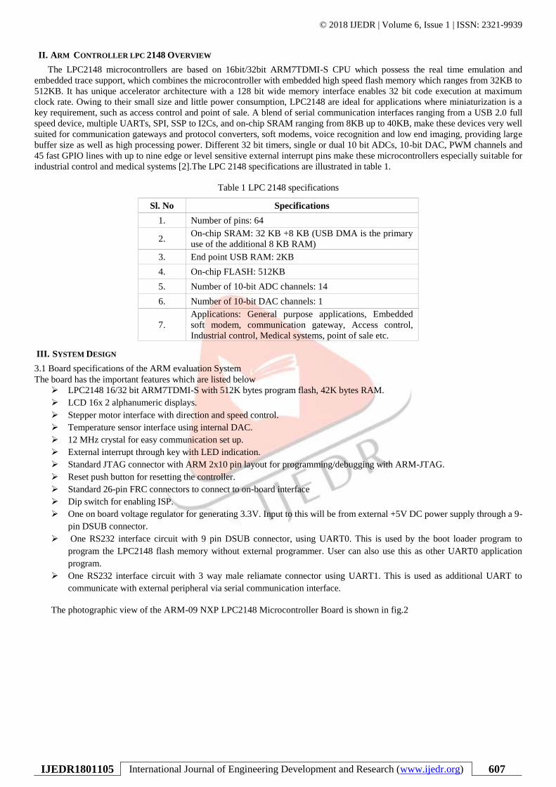
II. ARM CONTROLLER LPC 2148 OVERVIEW
The LPC2148 microcontrollers are based on 16bit/32bit ARM7TDMI-S CPU which possess the real time emulation and
embedded trace support, which combines the microcontroller with embedded high speed flash memory which ranges from 32KB to
512KB. It has unique accelerator architecture with a 128 bit wide memory interface enables 32 bit code execution at maximum
clock rate. Owing to their small size and little power consumption, LPC2148 are ideal for applications where miniaturization is a
key requirement, such as access control and point of sale. A blend of serial communication interfaces ranging from a USB 2.0 full
speed device, multiple UARTs, SPI, SSP to I2Cs, and on-chip SRAM ranging from 8KB up to 40KB, make these devices very well
suited for communication gateways and protocol converters, soft modems, voice recognition and low end imaging, providing large
buffer size as well as high processing power. Different 32 bit timers, single or dual 10 bit ADCs, 10-bit DAC, PWM channels and
45 fast GPIO lines with up to nine edge or level sensitive external interrupt pins make these microcontrollers especially suitable for
industrial control and medical systems [2].The LPC 2148 specifications are illustrated in table 1.
Table 1 LPC 2148 specifications
Sl. No Specifications
1. Number of pins: 64
2. On-chip SRAM: 32 KB +8 KB (USB DMA is the primary
use of the additional 8 KB RAM)
3. End point USB RAM: 2KB
4. On-chip FLASH: 512KB
5. Number of 10-bit ADC channels: 14
6. Number of 10-bit DAC channels: 1
7.
Applications: General purpose applications, Embedded
soft modem, communication gateway, Access control,
Industrial control, Medical systems, point of sale etc.
III. SYSTEM DESIGN
3.1 Board specifications of the ARM evaluation System
The board has the important features which are listed below
➢ LPC2148 16/32 bit ARM7TDMI-S with 512K bytes program flash, 42K bytes RAM.
➢ LCD 16x 2 alphanumeric displays.
➢ Stepper motor interface with direction and speed control.
➢ Temperature sensor interface using internal DAC.
➢ 12 MHz crystal for easy communication set up.
➢ External interrupt through key with LED indication.
➢ Standard JTAG connector with ARM 2x10 pin layout for programming/debugging with ARM-JTAG.
➢ Reset push button for resetting the controller.
➢ Standard 26-pin FRC connectors to connect to on-board interface
➢ Dip switch for enabling ISP.
➢ One on board voltage regulator for generating 3.3V. Input to this will be from external +5V DC power supply through a 9-
pin DSUB connector.
➢ One RS232 interface circuit with 9 pin DSUB connector, using UART0. This is used by the boot loader program to
program the LPC2148 flash memory without external programmer. User can also use this as other UART0 application
program.
➢ One RS232 interface circuit with 3 way male reliamate connector using UART1. This is used as additional UART to
communicate with external peripheral via serial communication interface.
The photographic view of the ARM-09 NXP LPC2148 Microcontroller Board is shown in fig.2

© 2018 IJEDR | Volume 6, Issue 1 | ISSN: 2321-9939
IJEDR1801105 International Journal of Engineering Development and Research (www.ijedr.org) 608
Fig.2 Photographic view of the proposed system
3.2 Proposed System Specifications
The system specifications are illustrated in table.2.
Table 1 LPC 2148 specifications
Sl. No System Specifications
1. Domain :Microprocessors and Microcontrollers, Assembly
language programming
2. ARM controller: LPC2148 32-bit RISC microcontroller from
NXP founded by Philips.
3. LCD: 16x2 alphanumeric display.
4. Desktop computer: Dual core, 1 GB RAM, Processor speed 2.5
GHz.
5. Port line: P0.2-P0.7
6. POT details: 50K ANVI POT for LCD contrast.
7. Software: Keil µ vision-4
8. In-system Programming (ISP): Flash magic software can be used
to download the HEX files to the flash magic of the controller.
9.
Serial communication: RS 232 cross cable connections required
for establishing communication between the evaluation board and
a display terminal/host computer.
10. Applications: Display of any text, numbers etc on the LCD
3.3 LCD interface
A 16x2 Alphanumeric LCD display with back light is provided along with the Evaluation board. The LCD is interfaced using the 4
bit mode. The circuit schematic for LCD interface is illustrated in figure 3.
Register select (RS): There are two registers inside the LCD and the RS pin is used for their selection as follows. If RS=0, the
instruction command code register is selected which allows the user to send a command such as clear display, cursor at home and
so on. On the other hand when RS=1, the data register is selected which allows the user to send the data to be displayed on the LCD
(or data to be retrieved). In our proposed system
RS=0 for sending command to the LCD, controlled by port P0.2
RS=1 for sending data to the LCD, controlled by port P0.2
R/W, Read/Write: R/W input allows the user to write information into the LCD or read information from it. R/W=0 for writing and
R/W=1 for Reading.
In the proposed system
R/W=0 for writing from the LCD, normally it is grounded.
R/W=1 for reading from the LCD.
Enable EN: the LCD uses the Enable pin to latch the information presented to its data pins. When data is supplied or send to the
data pins, a high to low pulse must be applied to this pin so that the LCD can latch in the data available at the data pins.
In the proposed system
EN=0 for Disabling the LCD
EN=1 for Enabling the LCD, controlled by port P0.3
© 2018 IJEDR | Volume 6, Issue 1 | ISSN: 2321-9939
IJEDR1801105 International Journal of Engineering Development and Research (www.ijedr.org) 609
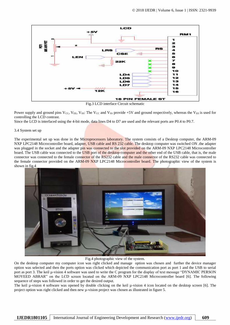
Fig.3 LCD interface Circuit schematic
Power supply and ground pins VCC, VEE, VSS: The VCC and VSS provide +5V and ground respectively, whereas the VEE is used for
controlling the LCD contrast.
Since the LCD is interfaced using the 4-bit mode, data lines D4 to D7 are used and the relevant ports are P0.4 to P0.7.
3.4 System set up
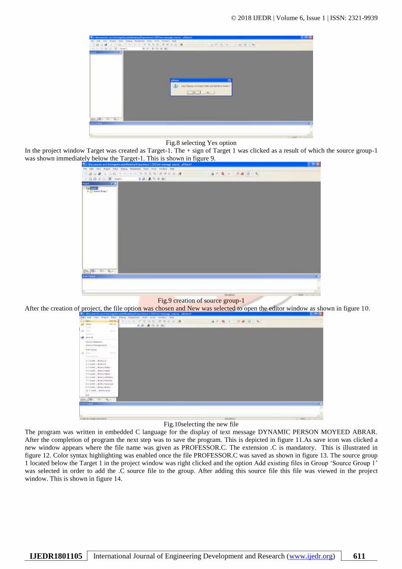
The experimental set up was done in the Microprocessors laboratory. The system consists of a Desktop computer, the ARM-09
NXP LPC2148 Microcontroller board, adapter, USB cable and RS 232 cable. The desktop computer was switched ON .the adapter
was plugged in the socket and the adapter pin was connected to the slot provided on the ARM-09 NXP LPC2148 Microcontroller
board. The USB cable was connected to the USB port of the desktop computer and the other end of the USB cable, that is, the male
connector was connected to the female connector of the RS232 cable and the male connector of the RS232 cable was connected to
the female connector provided on the ARM-09 NXP LPC2148 Microcontroller board. The photographic view of the system is
shown in fig.4
Fig.4 photographic view of the system.
On the desktop computer my computer icon was right clicked and manage option was chosen and further the device manager
option was selected and then the ports option was clicked which depicted the communication port as port 1 and the USB to serial
port as port 3. The keil µ-vision 4 software was used to write the C program for the display of text message “DYNAMIC PERSON
MOYEED ABRAR” on the LCD screen located on the ARM-09 NXP LPC2148 Microcontroller board [6]. The following
sequence of steps was followed in order to get the desired output.
The keil µ-vision 4 software was opened by double clicking on the keil µ-vision 4 icon located on the desktop screen [6]. The
project option was right clicked and then new µ-vision project was chosen as illustrated in figure 5.

© 2018 IJEDR | Volume 6, Issue 1 | ISSN: 2321-9939
IJEDR1801105 International Journal of Engineering Development and Research (www.ijedr.org) 610
Fig.5 selecting new µ-vision project
Create New project window appears on the screen. A folder with the named Experiment LCD was created on the desktop screen
and the file with name Text message was saved in the folder Experiment LCD as shown in figure 6.
Fig.6 creation of folder and naming the file.
Another new window named Select Device for Target ‘Target 1’appeared where the user has to select the ARM microcontroller.
The NXP series founded by Philips was chosen and in this category the LPC2148 was selected. The LPC2148 features were
displayed and OK option was clicked. This is illustrated in figure 7.
Fig.7 selecting the microcontroller LPC2148.
A new window appears named µ-vision copy startup project folder and Add file to the project with two options Yes and No. the
Yes option was chosen as depicted in figure 8.
© 2018 IJEDR | Volume 6, Issue 1 | ISSN: 2321-9939
IJEDR1801105 International Journal of Engineering Development and Research (www.ijedr.org) 611
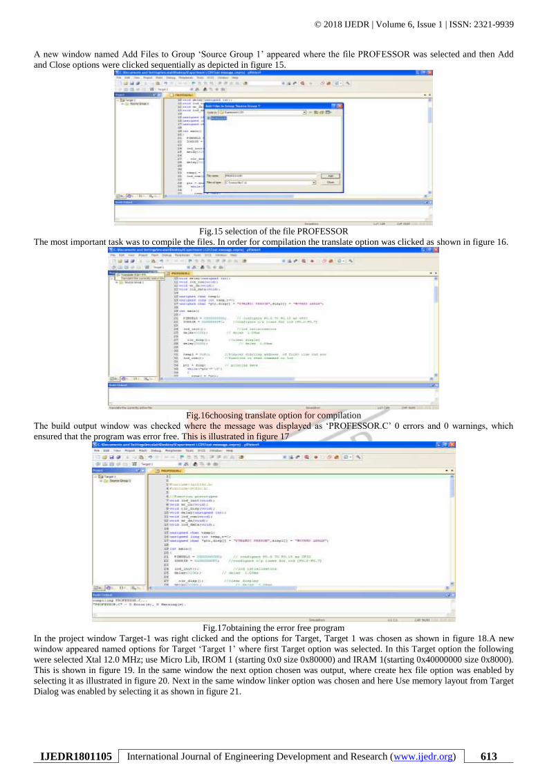
Fig.8 selecting Yes option
In the project window Target was created as Target-1. The + sign of Target 1 was clicked as a result of which the source group-1
was shown immediately below the Target-1. This is shown in figure 9.
Fig.9 creation of source group-1
After the creation of project, the file option was chosen and New was selected to open the editor window as shown in figure 10.
Fig.10selecting the new file
The program was written in embedded C language for the display of text message DYNAMIC PERSON MOYEED ABRAR.
After the completion of program the next step was to save the program. This is depicted in figure 11.As save icon was clicked a
new window appears where the file name was given as PROFESSOR.C. The extension .C is mandatory. This is illustrated in
figure 12. Color syntax highlighting was enabled once the file PROFESSOR.C was saved as shown in figure 13. The source group
1 located below the Target 1 in the project window was right clicked and the option Add existing files in Group ‘Source Group 1’
was selected in order to add the .C source file to the group. After adding this source file this file was viewed in the project
window. This is shown in figure 14.

© 2018 IJEDR | Volume 6, Issue 1 | ISSN: 2321-9939
IJEDR1801105 International Journal of Engineering Development and Research (www.ijedr.org) 612
Fig.11saving the program
Fig.12 naming the file as PROFESSOR.C
Fig.13colour syntax highlighting after saving the file
Fig.14 adding existing files to source group-1.
© 2018 IJEDR | Volume 6, Issue 1 | ISSN: 2321-9939
IJEDR1801105 International Journal of Engineering Development and Research (www.ijedr.org) 613
A new window named Add Files to Group ‘Source Group 1’ appeared where the file PROFESSOR was selected and then Add
and Close options were clicked sequentially as depicted in figure 15.
Fig.15 selection of the file PROFESSOR
The most important task was to compile the files. In order for compilation the translate option was clicked as shown in figure 16.
Fig.16choosing translate option for compilation
The build output window was checked where the message was displayed as ‘PROFESSOR.C’ 0 errors and 0 warnings, which
ensured that the program was error free. This is illustrated in figure 17
Fig.17obtaining the error free program
In the project window Target-1 was right clicked and the options for Target, Target 1 was chosen as shown in figure 18.A new
window appeared named options for Target ‘Target 1’ where first Target option was selected. In this Target option the following
were selected Xtal 12.0 MHz; use Micro Lib, IROM 1 (starting 0x0 size 0x80000) and IRAM 1(starting 0x40000000 size 0x8000).
This is shown in figure 19. In the same window the next option chosen was output, where create hex file option was enabled by
selecting it as illustrated in figure 20. Next in the same window linker option was chosen and here Use memory layout from Target
Dialog was enabled by selecting it as shown in figure 21.

© 2018 IJEDR | Volume 6, Issue 1 | ISSN: 2321-9939
IJEDR1801105 International Journal of Engineering Development and Research (www.ijedr.org) 614
Fig.18choosing options for Target, Target-1
Fig.19enabling Xtal, use Micro Lib, IROM and IRAM1
Fig.20selecting create hex file option
Fig.21enabling use memory layout from target dialog

© 2018 IJEDR | Volume 6, Issue 1 | ISSN: 2321-9939
IJEDR1801105 International Journal of Engineering Development and Research (www.ijedr.org) 615
Finally, to come out of this window OK option was clicked. Lastly, Rebuild icon was clicked for building all the source files such
as .C, .h etc. This is shown in figure 22.
Fig.22selecting rebuild option for building source file.
This created the .HEX file as 0 Error(s), 0 Warning(s) and this was displayed in the Build output window. This is illustrated in
figure 23.
Fig.23creation of .HEX file
IV. EXPERIMENTAL RESULTS AND DISCUSSION
The output in the form of text message DYNAMIC PERSON MOYEED ABRAR was displayed on the LCD. The first part of the
text DYNAMIC PERSON was displayed in the first row and the last part of the text MOYEED ABRAR was displayed on the last
row. The Flash Magic software was opened by double clicking the Flash magic icon located on the desktop. The five mandatory
steps were done in order to get the final output on the LCD screen.
STEP1: COMMUNICATIONS
In this step the following selections are done
Device : LPC2148
Com port : COM 3 (as the USB cable is connected to this port)
Baud rate : 19200
Interface : None (ISP)
Oscillator : 12 MHz
This is shown in figure 24.
Fig.24 STEP1: COMMUNICATIONS
© 2018 IJEDR | Volume 6, Issue 1 | ISSN: 2321-9939
IJEDR1801105 International Journal of Engineering Development and Research (www.ijedr.org) 616
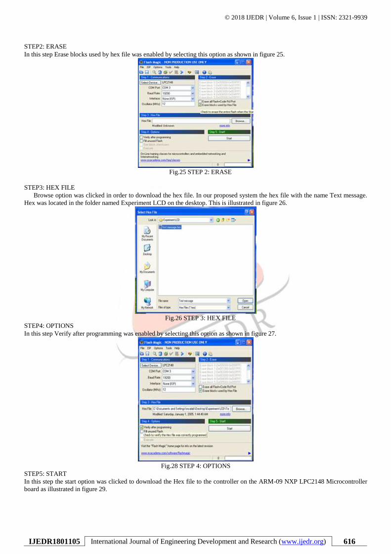
STEP2: ERASE
In this step Erase blocks used by hex file was enabled by selecting this option as shown in figure 25.
Fig.25 STEP 2: ERASE
STEP3: HEX FILE
Browse option was clicked in order to download the hex file. In our proposed system the hex file with the name Text message.
Hex was located in the folder named Experiment LCD on the desktop. This is illustrated in figure 26.
Fig.26 STEP 3: HEX FILE
STEP4: OPTIONS
In this step Verify after programming was enabled by selecting this option as shown in figure 27.
Fig.28 STEP 4: OPTIONS
STEP5: START
In this step the start option was clicked to download the Hex file to the controller on the ARM-09 NXP LPC2148 Microcontroller
board as illustrated in figure 29.

© 2018 IJEDR | Volume 6, Issue 1 | ISSN: 2321-9939
IJEDR1801105 International Journal of Engineering Development and Research (www.ijedr.org) 617
Fig. 29 STEP 5: START
As soon as step 5 was completed the text message DYNAMIC PERSON MOYEED ABRAR was displayed on the LCD screen
as shown in figure 30.
Fig.30 Photographic view of the output DYNAMIC PERSON MOYEED ABRAR
In order to display another text DYNAMIC PROFESSOR MOYEED ABRAR suitable changes were made in the program but the
complete desired text was not displayed as the LCD on the ARM-09 NXP LPC2148 Microcontroller board is a 16x2 LCD. Just the
text DYNAMIC PROFESS MOYEED ABRAR was displayed on the screen. This is illustrated in figure 31.
Fig.31Display of text DYNAMIC PROFESS MOYEED ABRAR

© 2018 IJEDR | Volume 6, Issue 1 | ISSN: 2321-9939
IJEDR1801105 International Journal of Engineering Development and Research (www.ijedr.org) 618
V. CONCLUSION
The ARM-09 NXP LPC2148 Microcontroller board with many salient features is easy for the programmer to operate and is user
friendly. Care was taken in properly interconnecting the USB cable and the RS232 cable to the COM port and to the ARM-09
NXP LPC2148 Microcontroller board respectively. The ARM-09 NXP LPC2148 Microcontroller board with many salient
features is easy for the programmer to operate and is user friendly. The output in the form of text message DYNAMIC PERSON
MOYEED ABRAR obtained was very precise and clear. Various types of text messages can be displayed on the LCD depending
on the choice of the programmer. The main limitation is that the display being a 16x2 alphanumeric display, the text in the first
row cannot exceed 16 characters or numbers and similarly in the last row the text cannot exceed 16 characters or numbers. This
limitation can be overcome by using a different LCD which can display more text such as 32x2 alphanumeric display.
VI. ACKNOWLEDGMENT
First of all I would like to thank Almighty Allah by the grace of whom I reached the stage of completion of this work. This
avenue has been a turning point in my career to mold me into a thorough and dynamic Professional. My sincere thanks to the
Principal Dr. S Kamal Mohd. Azam, Vice Principal Dr. Ruksar Fatima and Dr. Asma Parveen H.O.D Computer Science and
Engineering department of my esteemed institution for their inspiration and support. Lastly I am also thankful to my beloved
Parents who have helped me pave this path to success.
REFERENCES
[1] Anil K Maini, V Agarwal, Electronic Devices and Circuits, New Delhi: Wiley India pvt.ltd, 2009.
[2] Datasheet LPC2141/42/44/46/48, Philips semiconductor, October 2005 pp.1-2.
[3] Andrew N Sloss, Dominic Symes, Chris Wright, ARM System Developer’s guide Designing and optimizing system
software. USA: Morgan Kaufman publications, 2004.
[4] Muhammad Ali Mazidi, Janice Gillespie Mazidi and Danny Causey, The x86 PC Assembly Language, Design and
Interfacing, India: Dorling Kindersley Pvt.ltd, fifth edition, 2011.
[5] Barry B. Brey, Introduction to the Microprocessor and Computer, The Intel Microprocessors – Architecture,
Programming and Interfacing, India: Dorling Kindersley Pvt.ltd, Pearson-Prentice Hall Eighth Edition, 2009.
[6] Trevor Martin, The Insiders guide to the Philips ARM7 based Microcontrollers, February 2005, pp.124-126.
[7] Chia-Ting Hsieh, Ghung-Yin Li, Tsung-Tai Wu, Chi-YenHuang, Ching-JuiTien, Kuang-Yao Lo, Chi-Huang Lin,
“Twisted Nematic Dual –View Liquid Crystal Display Based on Patterned Electrodes”, IEEE journals and magazines:
Journal of Display Technology, vol.10, pp. 464-469, June 2014.
[8] Chih-Lung Lin, Ming-Yang Deng, Chia-En Wu, Chih-Cheng Hsu, Chia-Lun Lee, “Hydrogenated Amorphous Silicon
Gate Driver With Low Leakage for Thin-Film Transistor Liquid Crystal Display Applications”, IEEE Transactions on
Electron Devices, vol.64, issue 8, pp. 3193-3198, August 2017.
[9] Jong-Man Kim, Dong-Gun Lee, Seung-Woo Lee, “Temperature-Dependent Behavioral Model of Active-Matrix Liquid
Crystal Displays for All Types of Liquid Crystals”, IEEE journals and Magazines: Journal of Display Technology,
vol.12, issue 9, pp. 881-887, September 2016.
[10] Byunghee Kim, Seungjae Lee, “Conducted emission reduction technologyfor liquid crystal display devices”, IEEE
International Symposium on Electromagnetic Compatibilty& Signal/Power Integrity (EMCSI), Washington DC, USA pp.
65-67, 2017.