
INTERCHANGE RAMP TERMINALS - againc.net · Highway Capacity Manual 2000 26-1 Chapter 26 -...
19
Highway Capacity Manual 2000 26-i Chapter 26 - Interchange Ramp Terminals CHAPTER 26 INTERCHANGE RAMP TERMINALS CONTENTS I. INTRODUCTION ..................................................................................................... 26-1 Types of Interchanges ...................................................................................... 26-1 Diamond Interchanges .............................................................................. 26-1 Partial Cloverleaf Interchanges ................................................................. 26-1 Influence of Interchange Type on Turning Movements ............................. 26-3 Unique Operations at Signalized Diamond Interchanges ................................. 26-4 Queuing Characteristics ............................................................................ 26-5 Lane Change Movements ......................................................................... 26-6 Lane Utilization ......................................................................................... 26-6 Platoon Behavior ....................................................................................... 26-6 Demand Starvation ................................................................................... 26-7 Signal Phasing and Timing Strategies ...................................................... 26-7 II. METHODOLOGY .................................................................................................... 26-7 LOS Framework ............................................................................................... 26-7 Saturation Flow Rates for Interchange Lane Groups ....................................... 26-9 III. APPLICATIONS .................................................................................................... 26-10 IV. EXAMPLE PROBLEMS ......................................................................................... 26-11 V. REFERENCES ...................................................................................................... 26-11 APPENDIX A. TIMING CONSIDERATIONS FOR SIGNALIZED DIAMOND INTERCHANGES .............................................................. 26-11 Phasing Options ............................................................................................. 26-12 Establishing Offsets ....................................................................................... 26-13 APPENDIX B. ASSESSMENT OF ALTERNATIVE INTERCHANGE CONFIGURATIONS ................................................. 26-14 EXHIBITS Exhibit 26-1. Types of Diamond Interchanges ........................................................... 26-2 Exhibit 26-2. Types of Cloverleaf Interchanges .......................................................... 26-3 Exhibit 26-3. Effects of Interchange Type on Turning Movements ............................. 26-4 Exhibit 26-4. Typical Signalized Diamond Interchange .............................................. 26-5 Exhibit 26-5. Lane Change Movements at a Diamond Interchange ........................... 26-6 Exhibit 26-6. Movements in a Diamond Interchange .................................................. 26-8 Exhibit 26-7. Components of Interchange Delay ........................................................ 26-8 Exhibit 26-8. LOS Criteria for Interchanges ................................................................ 26-9 Exhibit 26-9. Framework for Comprehensive Interchange Ramp Terminal Analysis ................................................................................ 26-10 Exhibit A26-1. Common Signalization Schemes for Diamond Interchanges .............. 26-12 Exhibit A26-2. Four-Phase Plan with Overlap ............................................................. 26-13
Transcript of INTERCHANGE RAMP TERMINALS - againc.net · Highway Capacity Manual 2000 26-1 Chapter 26 -...
Highway Capacity Manual 2000
26-i Chapter 26 - Interchange Ramp Terminals
CHAPTER 26
INTERCHANGE RAMP TERMINALS
CONTENTS
I. INTRODUCTION ..................................................................................................... 26-1Types of Interchanges...................................................................................... 26-1
Diamond Interchanges .............................................................................. 26-1Partial Cloverleaf Interchanges ................................................................. 26-1Influence of Interchange Type on Turning Movements ............................. 26-3
Unique Operations at Signalized Diamond Interchanges................................. 26-4Queuing Characteristics............................................................................ 26-5Lane Change Movements ......................................................................... 26-6Lane Utilization ......................................................................................... 26-6Platoon Behavior ....................................................................................... 26-6Demand Starvation ................................................................................... 26-7Signal Phasing and Timing Strategies ...................................................... 26-7
II. METHODOLOGY .................................................................................................... 26-7LOS Framework ............................................................................................... 26-7Saturation Flow Rates for Interchange Lane Groups ....................................... 26-9
III. APPLICATIONS .................................................................................................... 26-10IV. EXAMPLE PROBLEMS......................................................................................... 26-11V. REFERENCES ...................................................................................................... 26-11APPENDIX A. TIMING CONSIDERATIONS FOR SIGNALIZED
DIAMOND INTERCHANGES .............................................................. 26-11Phasing Options ............................................................................................. 26-12Establishing Offsets ....................................................................................... 26-13
APPENDIX B. ASSESSMENT OF ALTERNATIVEINTERCHANGE CONFIGURATIONS ................................................. 26-14
EXHIBITS
Exhibit 26-1. Types of Diamond Interchanges ........................................................... 26-2Exhibit 26-2. Types of Cloverleaf Interchanges.......................................................... 26-3Exhibit 26-3. Effects of Interchange Type on Turning Movements ............................. 26-4Exhibit 26-4. Typical Signalized Diamond Interchange .............................................. 26-5Exhibit 26-5. Lane Change Movements at a Diamond Interchange ........................... 26-6Exhibit 26-6. Movements in a Diamond Interchange.................................................. 26-8Exhibit 26-7. Components of Interchange Delay ........................................................ 26-8Exhibit 26-8. LOS Criteria for Interchanges................................................................ 26-9Exhibit 26-9. Framework for Comprehensive Interchange Ramp
Terminal Analysis ................................................................................ 26-10Exhibit A26-1. Common Signalization Schemes for Diamond Interchanges .............. 26-12Exhibit A26-2. Four-Phase Plan with Overlap............................................................. 26-13


Highway Capacity Manual 2000
26-1 Chapter 26 - Interchange Ramp TerminalsIntroduction
I. INTRODUCTION
This chapter presents general material for analyzing interchange ramp terminalsinvolving freeways, major highways, and urban streets. Although the chapter presentsideas and concepts relating to most types of interchanges that include two intersections, itfocuses primarily on signalized, two-intersection diamond interchanges. The closeproximity of the two signalized intersections forming the diamond creates interactiveeffects that complicate the analysis. A complete methodology for predicting the impactof these effects is not yet available; this chapter therefore is primarily conceptual incontent.
TYPES OF INTERCHANGES
Several interchange types are recognized in the literature. The common types thatmay result in two closely spaced surface intersections are illustrated and discussed here.The single-point diamond interchange, with only one signalized intersection, also isillustrated. The term freeway is used here to denote a freeway, expressway, or a majorthrough highway.
Diamond Interchanges
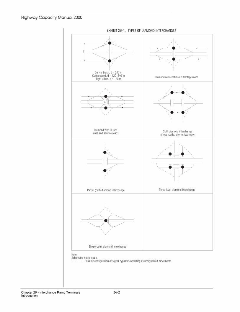
Most forms of diamond interchanges result in two or more closely spaced surfaceintersections, as illustrated in Exhibit 26-1. On a diamond interchange, only oneconnection is made for each freeway entry and exit, with one connection per quadrant.Left- and right-turning movements are used for entry to or exit from the two directions ofthe surface facility; diamond interchanges require left-turn movements. In rural areas, thejunction of diamond interchange ramps with the surface facility is often controlled bystop or yield signs. If traffic demand is high, signalization becomes necessary.
There are many variations on the diamond interchange. The typical diamond hasthree subcategories defined by the spacing of the intersections formed by the ramp-streetconnections. Conventional diamond interchanges provide a separation of 240 m or morebetween the two intersections. Compressed diamond interchanges have intersectionsspaced between 120 m and 240 m, and tight urban diamond interchanges feature spacingof less than 120 m.
Split diamond interchanges have freeway entry and exit ramps separated at the streetlevel, creating four intersections. Diamond configurations also can be combined withcontinuous one-way frontage roads. The frontage roads become one-way arterials, andturning movements at the intersections created by the diamond interchange become evenmore complex, due to the additional need to serve movements to and from the frontageroad. Separated U-turn lanes also may be added, removing U-turns from the signalscheme, if there is a signal. A partial diamond interchange has fewer than four ramps, sothat not all of the freeway-street or street-freeway movements are served. A three-leveldiamond interchange features two divided levels, so that ramps are necessary on bothfacilities to allow continuous through movements. Two interlocking split diamonds arecreated.
A single-point diamond interchange combines all the ramp movements into a singlesignalized intersection and has the advantage of operating as such. The design eliminatesthe critical issue of coordinating the operation of two closely spaced intersections.
All of these forms of diamond interchanges are depicted in Exhibit 26-1.
Partial Cloverleaf Interchanges
Partial cloverleaf interchanges—or parclos—are depicted in Exhibit 26-2. A varietyof partial cloverleaf interchanges can be created with one or two loop ramps. In suchcases, one or two of the outer ramps take the form of a diamond ramp, allowing amovement to take place by making a left turn. In some partial cloverleaf configurations,left turns also may be made onto or off of a loop ramp.
Highway Capacity Manual 2000
Chapter 26 - Interchange Ramp Terminals 26-2Introduction
EXHIBIT 26-1. TYPES OF DIAMOND INTERCHANGES
Note:Schematic, not to scale.
Conventional, d > 240 mCompressed, d = 120–240 m
Tight urban, d < 120 m Diamond with continuous frontage roads
Diamond with U-turnlanes and service roads Split diamond interchange
(cross roads, one- or two-way)
Partial (half) diamond interchange Three-level diamond interchange
d
Possible configuration of signal bypasses operating as unsignalized movements
Single-point diamond interchange

Highway Capacity Manual 2000
26-3 Chapter 26 - Interchange Ramp TerminalsIntroduction
EXHIBIT 26-2. TYPES OF CLOVERLEAF INTERCHANGES
Possible configuration of signal bypasses operating as unsignalized movements
Diamond Plus One Loop(Loop in any one of four quadrants) Parclo A, 4 Quadrants
Parclo AB, 2 Quadrants Parclo AB, 4 Quadrants
Parclo A, 2 Quadrants Parclo B, 4 Quadrants
Influence of Interchange Type on Turning Movements
The type of interchange has a major influence on turning movements. Movementsthat involve a right-side merge in one configuration become left turns in another.Movements approaching the interchange on the surface facility are also affected by theinterchange type, depending on whether the ramp movements involve left or right turns.Lane-changing and weaving movements also are affected.
Exhibit 26-3 shows the impact of interchange type on turning movements. The eightbasic movements between the freeway or major highway and the surface facility arelisted. The exhibit indicates whether the movement is a merge (M), diverge (D), orturning (T) movement at the surface facility terminal, and whether the movementinvolves a right-side (R) or left-side (L) maneuver.

Highway Capacity Manual 2000
Chapter 26 - Interchange Ramp Terminals 26-4Introduction
EXHIBIT 26-3. EFFECTS OF INTERCHANGE TYPE ON TURNING MOVEMENTS
N
E
S
W
Type of Movement Required for:
From Surface Street From Freeway/Highway
Type of Interchange S-E S-W N-W N-E E-N E-S W-N W-S
Diamond TRa TL TRa TL TRb TL TL TRb
Split Diamond TRa TL TRa TL TRb TL TL TRb
Parclo A - 4 Quad DR DR DR DR TRb TL TL TRb
Parclo A - 2 Quad TL TRa TL TRa TRb TL TL TRb
Parclo B - 4 Quad TRa TL TRa TL MR MR MR MRParclo B - 2 Quad TRa TL TRa TL TL TRb TRb TLParclo AB - 4 Quadc DR TL TR DR MR MR TL TRb
Parclo AB - 2 Quadc TRa DR TL TL TRb TL MR TL
Notes:Assumes freeway movements are eastbound and westbound. Movement types are with respect to surface street. Merges anddiverges may be with or without conflicting flows.T = turn against conflicting flow R = right-side movementM = merge with traffic L = left-side movementD = diverge from traffica. Could be diverge.b. Could be merge.c. Movements are correct only if loop ramps are on east side.
In selecting an appropriate type of interchange, the impacts on the turningmovements should be considered. Left-turning movements are always the most difficultin terms of efficiency of operation, and high-volume left-turning movements should beavoided, if possible. By selecting a type of interchange that requires left turns only ofminor movements, the overall operation can be enhanced considerably. However, it isnot always possible to accomplish this. Right-of-way limitations may preclude the use ofloop ramps, and economic and environmental constraints may make multilevel structuresundesirable. In the final analysis, a diamond configuration may be required even thoughit generates heavy left-turn volumes.
UNIQUE OPERATIONS AT SIGNALIZED DIAMOND INTERCHANGES
The signalized diamond interchange presents several unique situations for analysis.In effect, the diamond interchange configuration—except for that of the single-pointdiamond—places two signalized intersections in proximity, with heavier-than-usual left-turning and right-turning movements as vehicles enter and exit the freeway or majorhighway. The two intersections do not operate in isolation—each affects the other inways that are unique to the configuration. Some of these effects, however, also mayoccur at other signalized intersections that are closely spaced and that have a largeamount of left-turn movements. Two-quadrant parclos, for example, typically encounterthe same types of problems because their three-phase signalization is similar to that ofdiamond interchanges. These concepts, therefore, also can apply to similar
Highway Capacity Manual 2000
26-5 Chapter 26 - Interchange Ramp TerminalsIntroduction
noninterchange situations in which closely spaced signalized intersections—includingclosely spaced intersections adjacent to interchange ramp terminals—interact.
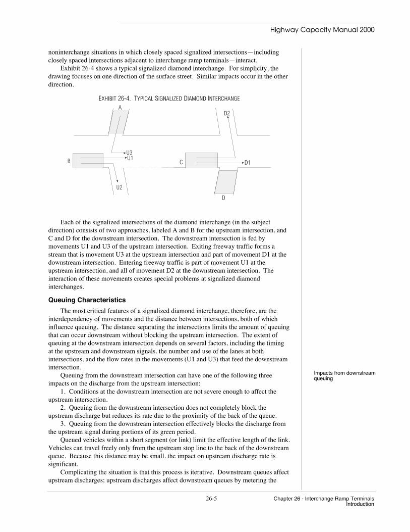
Exhibit 26-4 shows a typical signalized diamond interchange. For simplicity, thedrawing focuses on one direction of the surface street. Similar impacts occur in the otherdirection.
EXHIBIT 26-4. TYPICAL SIGNALIZED DIAMOND INTERCHANGE
A
B C
D
D1
D2
U3U1
U2
Each of the signalized intersections of the diamond interchange (in the subjectdirection) consists of two approaches, labeled A and B for the upstream intersection, andC and D for the downstream intersection. The downstream intersection is fed bymovements U1 and U3 of the upstream intersection. Exiting freeway traffic forms astream that is movement U3 at the upstream intersection and part of movement D1 at thedownstream intersection. Entering freeway traffic is part of movement U1 at theupstream intersection, and all of movement D2 at the downstream intersection. Theinteraction of these movements creates special problems at signalized diamondinterchanges.
Queuing Characteristics
The most critical features of a signalized diamond interchange, therefore, are theinterdependency of movements and the distance between intersections, both of whichinfluence queuing. The distance separating the intersections limits the amount of queuingthat can occur downstream without blocking the upstream intersection. The extent ofqueuing at the downstream intersection depends on several factors, including the timingat the upstream and downstream signals, the number and use of the lanes at bothintersections, and the flow rates in the movements (U1 and U3) that feed the downstreamintersection.
Impacts from downstreamqueuingQueuing from the downstream intersection can have one of the following three
impacts on the discharge from the upstream intersection:1. Conditions at the downstream intersection are not severe enough to affect the
upstream intersection.2. Queuing from the downstream intersection does not completely block the
upstream discharge but reduces its rate due to the proximity of the back of the queue.3. Queuing from the downstream intersection effectively blocks the discharge from
the upstream signal during portions of its green period.Queued vehicles within a short segment (or link) limit the effective length of the link.
Vehicles can travel freely only from the upstream stop line to the back of the downstreamqueue. Because this distance may be small, the impact on upstream discharge rate issignificant.
Complicating the situation is that this process is iterative. Downstream queues affectupstream discharges; upstream discharges affect downstream queues by metering the

Highway Capacity Manual 2000
Chapter 26 - Interchange Ramp Terminals 26-6Introduction
number of vehicles that can enter the short link between the diamond intersections. Thiscomplex relationship has not been fully studied and documented; therefore, the materialin this chapter is conceptual and is not based on a definitive model for signalizeddiamond interchange operations.
Lane Change MovementsInternal links Because of the turning movements at diamond interchanges, the internal link of the
surface street (the link between the two signalized diamond intersections) is subject toabnormally high numbers of lane-changing maneuvers. Exhibit 26-5 depicts thisphenomenon.
EXHIBIT 26-5. LANE CHANGE MOVEMENTS AT A DIAMOND INTERCHANGE
The lane changes occur because of origin-destination patterns. The turbulence of thelane changing can decrease the normal link speed. In addition, if there is queuing on thelink, it reduces the effective weaving or lane-changing distance, increasing the turbulenceand its potential effects on the traffic. In many cases, drivers try to pre-positionthemselves in the appropriate upstream lane, and left turns from the surface street canenter a turn bay at the entry point on the internal link. This tends to minimize lane-changing turbulence.
Lane Utilization
Because of the potential for heavy turning flows at signalized diamond interchanges,lane utilization may differ from that at other signalized intersections. At the downstreamintersection, heavy left-turning and through flows normally will segregate, and lane-useregulations generally encourage maximum segregation. While this might occur at anysignalized intersection with turning flows, the difference is in the impact on the upstreamintersection. Because the internal link generally is short, segregation may occur at theupstream intersection by driver selection or by designated signing and striping. Thus, theupstream approach flow can be segregated substantially into two flows, both of which arethrough flows at the upstream intersection: one will turn left at the downstreamintersection, and one will continue through it. This can create lane-use imbalances thatexceed those at normal intersections but that must be taken into account by creatingseparate lane groups for through vehicles at the upstream intersection.
Platoon Behavior
Because of the high volume of turns at a diamond interchange, it is difficult tomaintain platoons as vehicles pass through the two intersections. It is also difficult tomaintain the signal progression through the interchange. Platooned arrivals at thedownstream intersection come from two sources: left turns from an interchange ramp,and through movements from the surface street. The ramp may contribute a highervolume than the surface street and therefore would be the primary candidate forprogressed movement. In any case, the two sources arrive from two different signal
Highway Capacity Manual 2000
26-7 Chapter 26 - Interchange Ramp TerminalsIntroduction
phases. No matter what signalization is adopted, one of the movements will bedisadvantaged. Some portion of the lesser movement will arrive at the downstreamintersection during a red period, and the queued vehicles then will alter the platoonstructure that proceeds down the surface link.
Although heavy turning movements from the interchange ramps add vehicles toplatoons on the surface link, heavy left-turning movements of vehicles onto the freewayor major highway remove significant numbers of vehicles, creating gaps in the platoons.
Demand Starvation
Demand starvation occurs when portions of the green at the downstream intersectionare not used because conditions prevent vehicles at the upstream intersection fromreaching the downstream stop line. These conditions at the upstream intersection caninclude delays or blockage due to queue overflow from another lane group. Demandstarvation occurs in one of two ways:
1. Queues from the downstream intersection effectively block departures from theupstream intersection during part or all of the upstream green. This reduces the effectivegreen time for flow at the upstream location during the green time at the downstreamintersection.
2. Signal coordination between the two intersections is suboptimal even withoutdownstream queuing. As a result, sometimes the upstream signal is red while unsaturatedflow conditions prevail during the green at the downstream signal.
Signal Phasing and Timing StrategiesAppendix A provides moreinformation about thesignalization of diamondinterchanges
Because of the unique operational characteristics of signalized diamondinterchanges, special signal phase plans and timing often are appropriate. Appendix Acovers the signalization of diamond interchanges in greater detail. Capacity ofInterchange Ramp Terminals (1) describes a range of interchange signalization practices.The key point is that interchange performance is closely linked to signal timing, due tothe interdependence of flows, queuing, and timing.
II. METHODOLOGY
Because this chapter outlines only a conceptual approach for analyzing signalizeddiamond interchanges, it does not present a detailed analytic methodology withapplications. The conceptual methodology has two primary components:
• A level-of-service (LOS) framework, and• A framework for estimating saturation flow rates.
LOS FRAMEWORK
The recommended framework for LOS is to treat the diamond interchange as a pointrather than as a segment or system, and to focus on the total control delay experienced bydrivers as they move through the interchange.
Exhibit 26-6 shows the various movements at the diamond interchange. In theexhibit, movements are labeled as coming from the west intersection (W) or the eastintersection (E). An r designation indicates that the movement originates from one of theramps. The next two letters indicate whether the movement is a left turn (L), a right turn(R), or a through movement (T) first at the upstream intersection and then at thedownstream intersection, if both intersections are traversed. For example, the designationWrLT means a left turn from the west intersection ramp proceeding straight through theeast intersection.

Highway Capacity Manual 2000
Chapter 26 - Interchange Ramp Terminals 26-8Methodology
EXHIBIT 26-6. MOVEMENTS IN A DIAMOND INTERCHANGE
North
U-turn
U-turn
WrR
WR
WrLTWTTBA
CWest Intersection
ErLTETT
ETL
ER
ErR
E D
F
East Intersection
WTL
WrLL
ErLL
Exhibit 26-7 indicates the components of delay that must be included in the LOSanalysis of each movement. Each movement experiences the delay of each lane group ituses while passing through the interchange. Since the diamond interchange is beingconsidered as a point, the recommended LOS framework does not account for the traveltime between the two diamond intersections.
EXHIBIT 26-7. COMPONENTS OF INTERCHANGE DELAY
Movement Control Delay from Lane Groups of Approacha
WTLWTTWRWrRWrLTWrLLETLETTERErRErLTErLL
A and BA and BA onlyC onlyC and BC and BD and ED and ED onlyF onlyF and EF and E
Note:a. See Exhibit 26-6 for approach designations.
The control delay for each of the approach lane groups can be estimated using thesignalized and unsignalized intersection methodologies of Chapters 16 and 17, taking intoaccount progressive flows by estimating an appropriate arrival type. Unsignalized yieldand free-flow movements are to be included in the analysis, because performancedifferences between alternate interchange forms can be seen only by considering all rampterminal movements. For instance, the benefits of free-flow movements may be hidden

Highway Capacity Manual 2000
26-9 Chapter 26 - Interchange Ramp TerminalsMethodology
unless delays and volumes of all movements are incorporated, as shown in the example inAppendix B.
LOS for the individual groups is then determined from Exhibit 26-8, which uses LOScriteria for signalized intersections described in Chapter 16. If any lane group performspoorly—that is, if it falls in the LOS E or F range—the impact on the rest of theinterchange likely will not be identified unless queuing is analyzed in greater detail. Ifthere is severe queuing or upstream blockage, timing or design changes should beconsidered, regardless of the LOS. In all cases, spillback onto the mainline freewayshould be avoided because of the potential for high-speed rear-end accidents. To reduceramp queuing, the timing may be adjusted so that the surface street approaches, ratherthan the exit ramp approaches, perform at LOS F.
EXHIBIT 26-8. LOS CRITERIA FOR INTERCHANGES
Level of Service Delay (s/veh)
ABCDEF
≤ 10> 10–20> 20–35> 35–55> 55–80> 80
A comprehensive analysis would consider the interaction of flows, queues, andsignal timing. The LOS analysis could be based on complete movements through theinterchange, as defined in Exhibits 26-6 and 26-7. Such a procedure may be presented infuture editions of this manual.
Finally, a combined average control delay per vehicle for the interchange iscomputed:
dINT = Σ (div i )A−F
Σ (v i )A−F(26-1)
wheredINT = average control delay per vehicle for the interchange (s/veh),di = average control delay for Lane Group i on Approaches A–F (s/veh),
andvi = demand flow rate for Lane Group i (veh/h).
The equation includes the delays and the flow rates from all lane groups in A throughF. The computed delay therefore is the weighted average intersection delay of the tworamp terminal intersections. LOS is determined using the criteria in Exhibit 26-8.
SATURATION FLOW RATES FOR INTERCHANGE LANE GROUPS
The estimation of saturation flow rates at signalized intersections within a diamondor other interchange generally follows the procedures of Chapter 16. However, there arenecessary modifications for the unique interactions that occur in closely spaced,signalized intersections with high turning volumes. Currently, there are no fullydeveloped and evaluated methodologies for making these modifications, although somehave been proposed and are under study.

Highway Capacity Manual 2000
Chapter 26 - Interchange Ramp Terminals 26-10Applications
III. APPLICATIONS
Without a complete methodology, specific applications cannot be discussed orillustrated. However, the methodologies of Chapters 16 and 17 can be applied as a roughapproximation, as presented above, and the LOS criteria listed in Exhibit 26-8 then can beused to estimate LOS.
Nonetheless, such an application does not take into account all of the uniqueoperating conditions that affect operations at interchanges. Exhibit 26-9 lists theprincipal components of the framework for a complete interchange analysis.
EXHIBIT 26-9. FRAMEWORK FOR COMPREHENSIVE INTERCHANGE RAMP TERMINAL ANALYSIS
Inputs
• Traffic characteristics,• Geometrics, and• Control characteristics.
Signalized Movement Analysis
• Generally follow Chapter 16;• Modify to include
- Appropriate lane group definition, including pre-positioning,- Blockage by downstream queues,- Proximity to downstream queues (reduced speed),- Traffic pressure and interchange site effects,- Left- and right-turn radius effects, and- Demand starvation, and
• Analyze resulting capacity, queuing, delay, and LOS.
Weaving and Merge Movements
• Consider operational effects (no procedure defined in HCM) and• Analyze capacity, queuing, delay, and LOS.
Unsignalized Movements
• Apply Chapter 17 methodology and• Analyze resulting capacity, queuing, delay, and LOS.
Evaluation
• Measure performance (including queuing effects) of approach lane groups and movements through theinterchange;
• Perform an iterative analysis, to account for queue interactions;• Determine average performance of interchange;• Determine overall LOS of interchange; and• Analyze short interchange area segments comprising three to four closely spaced intersections.
When determining the LOS for diamond interchanges, the analyst should identifyseveral components integral to operational analysis, including, but not limited to
• Interchange geometry, including the number of lanes and storage;• Lane use and utilization;• Peak-hour turning volumes; and• Anticipated signal phasing and cycle lengths.The first step is to determine the current or projected queuing by lane group and by
traffic signal phase. If the queuing between traffic signals is due to the signal phasingand if this is causing backups that cannot be stored, then alternative signal phasing shouldbe identified so that the interchange may operate more efficiently within its geometriclimitations. However, the ramifications of this new signal phasing must be explored todetermine its impact on the operational efficiency of the interchange.

Highway Capacity Manual 2000
26-11 Chapter 26 - Interchange Ramp TerminalsApplications
An example of analyzing phasing would be to determine if the traffic queuing andstorage for three-phase operation at a diamond interchange will function without causingqueue spillback and additional traffic delays. If three-phase operation causes queuespillback and is inefficient, then changing to four-phase operation may be necessary.Four-phase signal timing basically allows each of the four approaches to the interchangeto operate on a separate phase. There are many different ways to achieve four-phaseoperation, by changing phase order and by sequencing signal overlaps. Three-phaseoperation allows two directions of travel to move concurrently most of the time, but four-phase operation requires that three phases wait while one is served. Changing from three-phase to four-phase operation at a diamond interchange normally creates a significantadverse impact on delays and LOS.
There are many other phasing sequences and offset relationships to consider.Variations on the basic sequence should stem from the interchange configuration, theability to store queues, system coordination elements, and the location of queue storage.The selection of leading or lagging (or both) left-turn arrows and overlap phasing may benecessary, as well as choice of protected, permissive, or protected-and-permissive left-turn phasing. Actuated operation is another factor. Appendix A presents signal timingconsiderations for signalized diamond interchanges; more discussion on this complextopic can be found in other references (1, 2).
IV. EXAMPLE PROBLEMS
Example problems are omitted from this chapter because a complete methodology isnot specified. However, Appendix B presents a numerical exercise illustrating thesimplified approach described earlier.
V. REFERENCES
1 Messer, C. J., and J. A. Bonneson. Capacity of Interchange Ramp Terminals.Final Report NCHRP Project 3-47. Texas A&M Research Foundations, CollegeStation, April 1997.
2. Akcelik, R. Interchange Capacity and Performance Model for HCM 2000.Technical Note, ARRB Transport Research Ltd., Vermont South, Australia,October 1998.
APPENDIX A. TIMING CONSIDERATIONS FOR SIGNALIZED DIAMONDINTERCHANGES
The signalization of two closely spaced intersections with heavy turning movements,as in a signalized diamond interchange, presents several major challenges. Most of theseinvolve the queuing of vehicles between the two intersections on the inside link, affectingoperations as described in this chapter. In addition, virtually every signalized diamondinterchange involves heavy left-turning movements, necessitating multiphasesignalization at both intersections and making progression and platoon cohesion along thesurface street difficult to maintain.

Highway Capacity Manual 2000
Chapter 26 - Interchange Ramp Terminals 26-12Appendix A
PHASING OPTIONS
Signalized diamond interchanges usually employ integrated phasing—that is, theyuse a single, often semiactuated controller for both intersections. Although there areseveral subalternates, the basic decision is whether to use a three-phase or a four-phasesystem. The three-phase system provides a more efficient use of time, but can lead toqueuing problems on the inside link. The four-phase system is less efficient in use oftime but avoids most queuing problems. Both are illustrated in Exhibit A26-1.
EXHIBIT A26-1. COMMON SIGNALIZATION SCHEMES FOR DIAMOND INTERCHANGES
Phase 2
Three Phase Four Phase
Phase 1 Phase 1
Phase 2
Phase 3 Phase 3
Phase 4
N/A
North
The basic three-phase scheme features a phase for through movements on the surfacestreet, a phase for movements from all inside links, and a phase for ramp movements. Asan alternative, Phases 2 and 3 can be switched.
The primary problem occurs in Phase 3. Left-turning vehicles from both ramps areentering the inside link and begin to queue at the downstream signal during the phase,which is now red. If queuing can cause a problem, this scheme should be avoided. Thenumber of vehicles that will accumulate on the inside link can be estimated by taking theeffective green time for Phase 3 and applying an estimated discharge rate for left-turningvehicles for each ramp. Given the number of lanes and the length of the inside link, thegeneral impact of queued vehicles (in each direction) can be assessed.
Note that in the three-phase sequence of Exhibit A26-1, Phase 1 follows Phase 3 andintroduces another set of vehicles into the inside link. If Phases 2 and 3 are switched, aphase discharging the inside link would follow and should help to reduce the impact ofthe queues.
Highway Capacity Manual 2000
26-13 Chapter 26 - Interchange Ramp TerminalsAppendix A
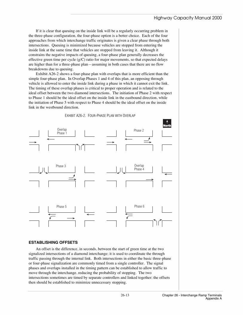
If it is clear that queuing on the inside link will be a regularly occurring problem inthe three-phase configuration, the four-phase option is a better choice. Each of the fourapproaches from which interchange traffic originates is given a clear phase through bothintersections. Queuing is minimized because vehicles are stopped from entering theinside link at the same time that vehicles are stopped from leaving it. Although itconstrains the negative impacts of queuing, a four-phase plan generally decreases theeffective green time per cycle (g/C) ratio for major movements, so that expected delaysare higher than for a three-phase plan—assuming in both cases that there are no flowbreakdowns due to queuing.
Exhibit A26-2 shows a four-phase plan with overlaps that is more efficient than thesimple four-phase plan. In Overlap Phases 1 and 4 of this plan, an opposing throughvehicle is allowed to enter the inside link during a phase in which it cannot exit the link.The timing of these overlap phases is critical to proper operation and is related to theideal offset between the two diamond intersections. The initiation of Phase 2 with respectto Phase 1 should be the ideal offset on the inside link in the eastbound direction, whilethe initiation of Phase 5 with respect to Phase 4 should be the ideal offset on the insidelink in the westbound direction.
EXHIBIT A26-2. FOUR-PHASE PLAN WITH OVERLAP
Phase 2OverlapPhase 1
Phase 3
North
Phase 5 Phase 6
OverlapPhase 4
ESTABLISHING OFFSETS
An offset is the difference, in seconds, between the start of green time at the twosignalized intersections of a diamond interchange; it is used to coordinate the throughtraffic passing through the internal link. Both intersections in either the basic three-phaseor four-phase signalization are commonly timed from a single controller. The signalphases and overlaps installed in the timing pattern can be established to allow traffic tomove through the interchange, reducing the probability of stopping. The twointersections sometimes are timed by separate controllers and linked together; the offsetsthen should be established to minimize unnecessary stopping.
Highway Capacity Manual 2000
Chapter 26 - Interchange Ramp Terminals 26-14Appendix A
Optimizing offsets When the through traffic on the surface street is a dominant feature and the rampflows are no larger than the normal turning volumes at other intersections, the standardideal offset may be used; this offset is equal to the travel time from the upstream to thedownstream stop line at the average running speed of traffic.
θij = LS
(A26-1)
whereθ ij = offset for through movements at Intersections i and j, between the start
of the downstream through green and the upstream green (s);L = length of the link (i-j) from the upstream stop line to the downstream
stop line (m); andS = average running speed on the surface street (m/s).
Normally, however, ramp movements are significant enough to create queuing on theinside link. In such cases, the ideal offset should be based on clearing the queue at thedownstream intersection:
θij = LS
− (1 − P ) *v *Cs
(A26-2)
whereP = proportion of vehicles arriving on green,v = arrival flow rate at the downstream intersection (veh/h),C = cycle length (s), ands = saturation flow rate at the downstream intersection (veh/h).
A third guideline for optimizing offsets is also available (1). This criterion is basedon minimizing demand starvation and is related to the maximum storage on the insidelink. To minimize demand starvation, the offset should be greater than or equal to thecomputation produced by Equation A26-3.
θij = LS
− 3,600 * N * Ls * l
(A26-3)
whereN = number of lanes on link i-j, andl = queue storage length per vehicle (m).
In general, the selection of an offset must consider many factors, including the flowlevel, the traffic pattern, and the degree of saturation at the downstream signal. However,to enhance the throughput efficiency during high-volume conditions, the offset should begreater than or equal to the larger value produced by Equations A26-2 and A26-3.
Ideal offsets often can be provided only in a single direction. Once an ideal offset isestablished in one direction, the offset in the other is often already determined. Althoughmultiphase operation at most interchange signals can provide some flexibility, othersignal timing requirements can dictate the opposing offset. In such cases, it is necessaryto consider both offsets and to determine a plan that is most effective for the overalloperation of the interchange, even though neither offset may be ideal.
APPENDIX B. ASSESSMENT OF ALTERNATIVE INTERCHANGECONFIGURATIONS
Assessment Three alternative configurations are presented for an interchange.Volumes (veh/h) and control delay (s/veh) are given for each movement. Control delay

Highway Capacity Manual 2000
26-15 Chapter 26 - Interchange Ramp TerminalsAppendix B
and overall LOS are determined to compare the alternatives and to illustrate the effect ofincluding all interchange movements in the calculations.
Alternative 1. Diamond, no free-flow movements or right turn on red (RTOR)
11 12
5 6
910 7
8
12 3
4
Movement No. Volume (veh/h) Delay (s/veh)
1 800 302 300 303 300 204 800 355 200 506 400 507 400 408 900 409 700 4510 400 2511 300 4512 300 45
Calculations• Total interchange delay (all 12 movements), 217,500 veh-s;• Total interchange volume (all 12 movements), 5,800 veh/h; and
• Average interchange control delay = 217,500
5,800= 37.5 s/veh (LOS D).
Alternative 2. Diamond with free-flow right turns to and from ramps
11 12
5 6
910 7
8
12 3
4
Movement No. Volume (veh/h) Delay (s/veh)1 800 302 300 03 300 204 800 355 200 506 400 07 400 08 900 409 700 4510 400 2511 300 012 300 45
Highway Capacity Manual 2000
Chapter 26 - Interchange Ramp Terminals 26-16Appendix B
Calculations• Total interchange delay (all 12 movements), 159,000 veh-s;• Total interchange volume (all 12 movements), 5,800 veh/h;• Total volume (excluding free-flow movements), 4,400 veh/h;
• Average interchange control delay (all volumes) = 159,000
5,800= 27.4 s/veh (LOS C),
and• Average interchange control delay (excluding free-flow volumes) =
159,0004,400
= 36.1 s/veh (LOS D).
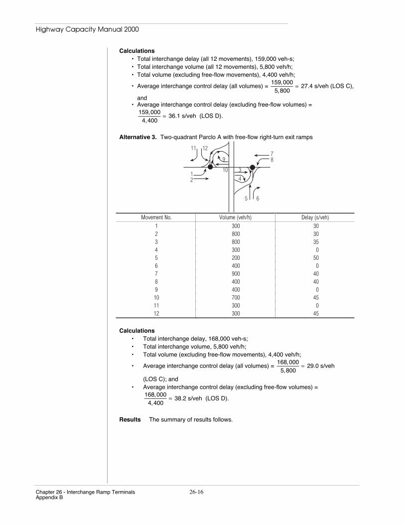
Alternative 3. Two-quadrant Parclo A with free-flow right-turn exit ramps
11 12
5 6
9
10
78
12
3
4
Movement No. Volume (veh/h) Delay (s/veh)
1 300 302 800 303 800 354 300 05 200 506 400 07 900 408 400 409 400 010 700 4511 300 012 300 45
Calculations• Total interchange delay, 168,000 veh-s;• Total interchange volume, 5,800 veh/h;• Total volume (excluding free-flow movements), 4,400 veh/h;
• Average interchange control delay (all volumes) = 168,000
5,800= 29.0 s/veh
(LOS C); and• Average interchange control delay (excluding free-flow volumes) =
168,0004,400
= 38.2 s/veh (LOS D).
Results The summary of results follows.

Highway Capacity Manual 2000
26-17 Chapter 26 - Interchange Ramp TerminalsAppendix B
Delay/LOS
Alternative Using all Volumes Excluding Free-Flow Volumes
Diamond, no free-flow movements or RTOR 37.5/D 37.5/D (no change)Diamond, with free-flow right turns to/from ramps 27.4/C 36.1/DTwo-quadrant Parclo A, with free-flow right-turnexit ramps
29.0/C 38.2/D
Considering all interchange volumes, the last two alternatives, which include free-flowmovements, outperform Alternative 1 by one service level. They perform about the samefor the given conditions. If free-flow volumes had been excluded, however, the benefits ofthis design feature would have been masked—the average delay and LOS of all threealternatives would be the same, as shown on the right side of the results summary.