Intentional Electromagnetic Interferences in Communication Devices
5
INTERNATIONAL JOURNAL OF SCIENTIFIC & TECHNOLOGY RESEARCH VOLUME 5, ISSUE 01, JANUARY 2016 ISSN 2277-8616 179 IJSTR©2016 www.ijstr.org Intentional Electromagnetic Interferences in Communication Devices Md. Abdul Nabi, R. Jayalakshmi, Dr. K. Umapathy Abstract: ―IEMI is the intentional generation of electromagnetic energy introducing noise or signals into electrical and/or electronic systems by interrupting, damaging and diverting these systems for jamming, terrorist or criminal [malicious] purposes." Keyword: Intentional Interference (Jamming), [IEMI] Intentional Electromagnetic Interference, [HPEM] High Power Electromagnetic, [HEMP] High Altitude Electromagnetic Pulse (or) [NEMP] Nuclear Electromagnetic Pulse, [EM] Electromagnetic terrorism, [UWB] Ultra-Wide Band Interference, System Standards. ———————————————————— I. INTRODUCTION [IEMI] Intentional electromagnetic interference it is sometimes known as, "EM Terrorism," is a new area for the interests of commercial and public concern .The existing threat by criminal (intentional) use of electromagnetic tools will be investigated. Intentional Electromagnetic Interference (IEMI) attacks reported and similar incidents will be analysed and discussed in regard to the aspects like motivation and technical skills of the culprits, characteristics for the generated environment of IEMI as well as effects on the target systems. Concluding common characteristics of the technical challenge of recognition and identification of an IEMI attack will lead to a discussion as well as backtracking the malfunction and destructions which observed to an external IEMI environment. II. [IEMI] INTENTIONAL ELECTROMAGNETIC INTERFERENCE [IEMI] Intentional Electromagnetic Interference is the intentional use of different malicious electromagnetic sources to induced interference (or permanent damage) in the victim system. First, it should will be mention the very severe incidents, with a huge loss of life, money, property or public relations have occurred due to the interference of unintentional electromagnetic energy and been described in literature (e.g., see IEC 61000-1-5) that grew out of the experience with electromagnetic effects on the systems in nuclear explosions on the atmosphere (so called NEMP) and High-Power Microwaves (HPM), many research operations in past has focused on the effects of electromagnetic energy in military systems such as aircraft, ships, communication systems. Fig.1. Typical IEMI interactions of radiated fields However from the late 1990’s, the focus has to some extent shifted. This shift in research is more due to the increase in the amount of sensitive and sophisticated electronic systems [commercial off the shelf (COTS)] which were used in critical civil infrastructure components and everyday systems are with the increased miniaturization these systems become more vulnerable to disturbances inherently. Thus, it is very important to investigate the offence for the threat of different civil systems from IEMI by traditional EMC methods and practices in the light of a human purpose behind these disturbance. IEMI research includes typical subjects such as: o Coupling of electromagnetic fields in to systems (either directly from a partially shielded exterior or dielectric) or on to cables. o Immunity levels of the underlying process for different seen events [why did it fail?]. o Adaption of existing methods of EMC for, e.g. protection against high frequency or wide band disturbances or unorthodox coupling paths. o System level threat analysis for the level of protection needed to judge [financial cost v/s risk and critical system]. Among all the Intentional electromagnetic interference some are as follows which we will discuss in this paper: Intentional Interference(Jamming) [HPEM]High power electromagnetic [HEMP]High-altitude electromagnetic pulse or [NEMP] Nuclear electromagnetic pulse [UWB]Ultra-Wideband INTENTIONAL INTERFERNCE (JAMMING) The intentional radiation of energy to produce noise or interference to another device or electronic system is known as Jamming. The conducting effectiveness of this type of activity depends on numerous intentional disruption in electronic or communication systems and it is a topic that can __________________________ Md. Abdul Nabi, R. Jayalakshmi, Dr. K. Umapathy M.Tech (EDT), SCSVMV UNIVERSITY, Kanchipuram, India Asst.prof, SCSVMV UNIVERSITY, Kanchipuram, India Assoc.prof, SCSVMV UNIVERSITY, Kanchipuram, India
-
Upload
ijstr-research-publication -
Category
Documents
-
view
21 -
download
4
description
Intentional Electromagnetic Interferences in Communication Devices
Transcript of Intentional Electromagnetic Interferences in Communication Devices

INTERNATIONAL JOURNAL OF SCIENTIFIC & TECHNOLOGY RESEARCH VOLUME 5, ISSUE 01, JANUARY 2016 ISSN 2277-8616
179 IJSTR©2016 www.ijstr.org
Intentional Electromagnetic Interferences in Communication Devices
Md. Abdul Nabi, R. Jayalakshmi, Dr. K. Umapathy
Abstract: ―IEMI is the intentional generation of electromagnetic energy introducing noise or signals into electrical and/or electronic systems by interrupting, damaging and diverting these systems for jamming, terrorist or criminal [malicious] purposes." Keyword: Intentional Interference (Jamming), [IEMI] Intentional Electromagnetic Interference, [HPEM] High Power Electromagnetic, [HEMP] High Altitude Electromagnetic Pulse (or) [NEMP] Nuclear Electromagnetic Pulse, [EM] Electromagnetic terrorism, [UWB] Ultra-Wide Band Interference, System Standards.
————————————————————
I. INTRODUCTION [IEMI] Intentional electromagnetic interference it is sometimes known as, "EM Terrorism," is a new area for the interests of commercial and public concern .The existing threat by criminal (intentional) use of electromagnetic tools will be investigated. Intentional Electromagnetic Interference (IEMI) attacks reported and similar incidents will be analysed and discussed in regard to the aspects like motivation and technical skills of the culprits, characteristics for the generated environment of IEMI as well as effects on the target systems. Concluding common characteristics of the technical challenge of recognition and identification of an IEMI attack will lead to a discussion as well as backtracking the malfunction and destructions which observed to an external IEMI environment.
II. [IEMI] INTENTIONAL ELECTROMAGNETIC INTERFERENCE [IEMI] Intentional Electromagnetic Interference is the intentional use of different malicious electromagnetic sources to induced interference (or permanent damage) in the victim system. First, it should will be mention the very severe incidents, with a huge loss of life, money, property or public relations have occurred due to the interference of unintentional electromagnetic energy and been described in literature (e.g., see IEC 61000-1-5) that grew out of the experience with electromagnetic effects on the systems in nuclear explosions on the atmosphere (so called NEMP) and High-Power Microwaves (HPM), many research operations in past has focused on the effects of electromagnetic energy in military systems such as aircraft, ships, communication systems.
Fig.1. Typical IEMI interactions of radiated fields
However from the late 1990’s, the focus has to some extent shifted. This shift in research is more due to the increase in the amount of sensitive and sophisticated electronic systems [commercial off the shelf (COTS)] which were used in critical civil infrastructure components and everyday systems are with the increased miniaturization these systems become more vulnerable to disturbances inherently. Thus, it is very important to investigate the offence for the threat of different civil systems from IEMI by traditional EMC methods and practices in the light of a human purpose behind these disturbance. IEMI research includes typical subjects such as: o Coupling of electromagnetic fields in to systems (either
directly from a partially shielded exterior or dielectric) or on to cables.
o Immunity levels of the underlying process for different seen events [why did it fail?].
o Adaption of existing methods of EMC for, e.g. protection against high frequency or wide band disturbances or unorthodox coupling paths.
o System level threat analysis for the level of protection needed to judge [financial cost v/s risk and critical system].
Among all the Intentional electromagnetic interference some are as follows which we will discuss in this paper:
Intentional Interference(Jamming)
[HPEM]High power electromagnetic
[HEMP]High-altitude electromagnetic pulse or [NEMP] Nuclear electromagnetic pulse
[UWB]Ultra-Wideband
INTENTIONAL INTERFERNCE (JAMMING) The intentional radiation of energy to produce noise or interference to another device or electronic system is known as Jamming. The conducting effectiveness of this type of activity depends on numerous intentional disruption in electronic or communication systems and it is a topic that can
__________________________
Md. Abdul Nabi, R. Jayalakshmi, Dr. K. Umapathy
M.Tech (EDT), SCSVMV UNIVERSITY, Kanchipuram, India
Asst.prof, SCSVMV UNIVERSITY, Kanchipuram, India
Assoc.prof, SCSVMV UNIVERSITY, Kanchipuram, India
INTERNATIONAL JOURNAL OF SCIENTIFIC & TECHNOLOGY RESEARCH VOLUME 5, ISSUE 01, JANUARY 2016 ISSN 2277-8616
180 IJSTR©2016 www.ijstr.org
be considered in data communication link design, especially with the increase of dependence on wireless communication technology as the primary communication medium for critical systems. A practical example of intentional interference is a technique known as jamming. This condition is the created through the intentional emission or reflection of electromagnetic energy of signals for the purpose of disrupting the electromagnetic signals of another system. This technique can be utilized for a narrow band or wide band portions of the electromagnetic spectrum. Its effective ability to jam a signal or group of signals typically requires the use of a high-power transmitter which produces a signal and it is stronger than the target signal. The susceptibility of the receiver is also an important factor with in the amount of transmission power necessary to effectively jam or disrupt a communication link or system. Intentional interference is having the capability of disrupting radio communications, radar and radio navigation systems. The transmission of RF energy or signals at a specific frequency or frequency band of sufficient levels can essentially overpower or cause significantly reduced signal integrity.
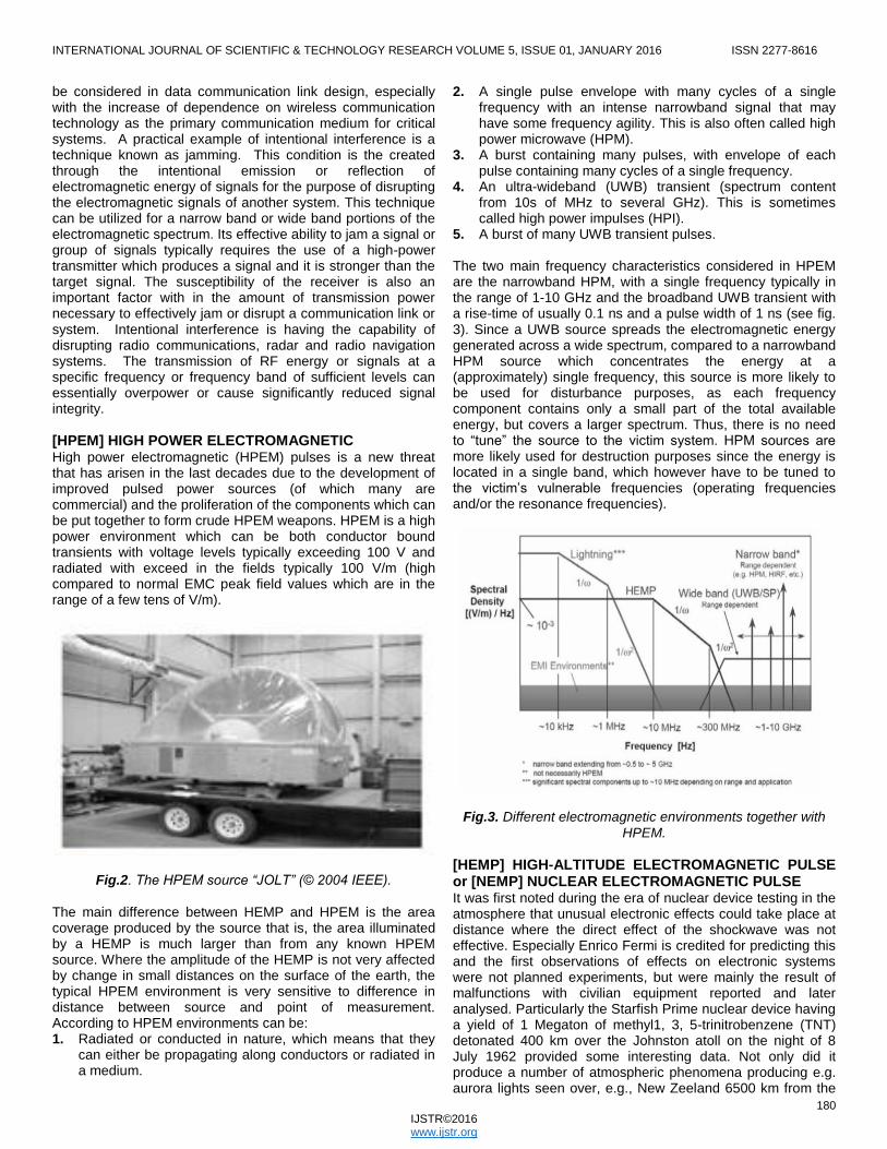
[HPEM] HIGH POWER ELECTROMAGNETIC High power electromagnetic (HPEM) pulses is a new threat that has arisen in the last decades due to the development of improved pulsed power sources (of which many are commercial) and the proliferation of the components which can be put together to form crude HPEM weapons. HPEM is a high power environment which can be both conductor bound transients with voltage levels typically exceeding 100 V and radiated with exceed in the fields typically 100 V/m (high compared to normal EMC peak field values which are in the range of a few tens of V/m).
Fig.2. The HPEM source “JOLT” (© 2004 IEEE).
The main difference between HEMP and HPEM is the area coverage produced by the source that is, the area illuminated by a HEMP is much larger than from any known HPEM source. Where the amplitude of the HEMP is not very affected by change in small distances on the surface of the earth, the typical HPEM environment is very sensitive to difference in distance between source and point of measurement. According to HPEM environments can be: 1. Radiated or conducted in nature, which means that they
can either be propagating along conductors or radiated in a medium.
2. A single pulse envelope with many cycles of a single frequency with an intense narrowband signal that may have some frequency agility. This is also often called high power microwave (HPM).
3. A burst containing many pulses, with envelope of each pulse containing many cycles of a single frequency.
4. An ultra-wideband (UWB) transient (spectrum content from 10s of MHz to several GHz). This is sometimes called high power impulses (HPI).
5. A burst of many UWB transient pulses. The two main frequency characteristics considered in HPEM are the narrowband HPM, with a single frequency typically in the range of 1-10 GHz and the broadband UWB transient with a rise-time of usually 0.1 ns and a pulse width of 1 ns (see fig. 3). Since a UWB source spreads the electromagnetic energy generated across a wide spectrum, compared to a narrowband HPM source which concentrates the energy at a (approximately) single frequency, this source is more likely to be used for disturbance purposes, as each frequency component contains only a small part of the total available energy, but covers a larger spectrum. Thus, there is no need to ―tune‖ the source to the victim system. HPM sources are more likely used for destruction purposes since the energy is located in a single band, which however have to be tuned to the victim’s vulnerable frequencies (operating frequencies and/or the resonance frequencies).
Fig.3. Different electromagnetic environments together with HPEM.
[HEMP] HIGH-ALTITUDE ELECTROMAGNETIC PULSE or [NEMP] NUCLEAR ELECTROMAGNETIC PULSE It was first noted during the era of nuclear device testing in the atmosphere that unusual electronic effects could take place at distance where the direct effect of the shockwave was not effective. Especially Enrico Fermi is credited for predicting this and the first observations of effects on electronic systems were not planned experiments, but were mainly the result of malfunctions with civilian equipment reported and later analysed. Particularly the Starfish Prime nuclear device having a yield of 1 Megaton of methyl1, 3, 5-trinitrobenzene (TNT) detonated 400 km over the Johnston atoll on the night of 8 July 1962 provided some interesting data. Not only did it produce a number of atmospheric phenomena producing e.g. aurora lights seen over, e.g., New Zeeland 6500 km from the

INTERNATIONAL JOURNAL OF SCIENTIFIC & TECHNOLOGY RESEARCH VOLUME 5, ISSUE 01, JANUARY 2016 ISSN 2277-8616
181 IJSTR©2016 www.ijstr.org
Johnston atoll, but also numerous electromagnetic effects were witnessed. In Hawaii, separated by 1400 km from the Johnston atoll radio communication was not possible for 30 min due to the disruptions in the ionosphere, street lights were destroyed, car alarms and air sirens were triggered at the time of the explosion, fuses were reported to be blown out all over the island and isolation transformers were damaged. The test from the Soviet Union in 1962 over Kazakhstan produced similar results with reports of failure of diesel generators, damaged insulators on Power lines, affected antenna systems, failure of communications lines and even an affected communications lines buried over 600 km away. HEMP is generated by several complex processes in the atmosphere at approximately an altitude of about 40 to 400 km but can shortly be said to occur as an effect of the matter and radiation created from the nuclear explosion interacting with matter in the atmosphere and the magnetic field of the earth. The area coverage will be dependent on the actual height of the nuclear explosion in the atmosphere, but will not be a linear function of the height. A nuclear explosion at an altitude of 30 km or more will affect all of northern Europe
Fig.4. A nuclear explosion at an altitude of 30 km or more will affect all of northern Europe
Even though standards give the HEMP waveform as 2.5/25 ns and 50 kV/m amplitude [often used for testing immunity] describes the early time component of the HEMP electric field (E1). The complete, no classified waveform of HEMP consists of: 1. Early time (E1), (last about 1 μs) 50 kV/m peak 2. Intermediated (E2) (1 μs to 1 ms) 100 V/m peak 3. Late time pulse (E3) (also known as the magneto
hydrodynamic pulse (which can last up to several minutes) (40 mV/m peak).
In part due to the curvature of the earth but also due to the different physical processes when creating the HEMP. Observe that the electric field values are dependent on the polarization and also that the actual waveforms from an HEMP is not publicly available. All of these three components affect electronic systems differently as the wave Lengths associated with them couples differently to objects of different sizes (and general direction compared to the polarization of the electric and magnetic field). For instance, the E1 component can propagate through apertures (due to small wavelength) and, due to the high electric field strength, create breakdown inside systems and the E3 component, even though very weak in strength, can cause problems since it will couple to long power cables and induce currents that may, e.g., saturate transformers. However, it is the synergy between the different
components that is the biggest concern. Damage caused by earlier components will increase the effects of next, e.g., E1 may trigger or cause a breakdown of surge arresters, which will leave systems unprotected from the energy of the E2 and/or E3 component. The physical processes that create the HEMP will, however, not be discussed further; nonetheless the historical role and influence that HEMP has had on EMC research cannot be stressed enough.
[UWB]ULTRA –WIDE BAND [UWB]Ultra-Wideband Radio uses radio impulses to transmit information. The key concept underlying UWB radio by using low power spread spectrum over a very wide bandwidth, one may communicate information without seriously degrading the performance of other narrow band users with in the same frequency range. An important area of research in UWB radio is to quantify the effect that UWB transmission will have systems with which spectrum is shared. Radio amateurs are one of the groups concerned with these issue because there are bands allocated for amateur radio within the possible range of UWB systems in future. This paper describes the results of sensitivity and linearity measurements performed with a receiver systems which were supplied by the American Radio Relay League (ARRL) to quantify the effects of UWB signals. Testing were performed at the [USC] University of Southern California, using the experimental UWB transmitter and instrumentation of USC’s Ultra Lab. The receiver and its antenna were supplied by the ARRL, which also provided samples of their standard receiver test procedures. Sophisticated radio amateurs often use their receiving equipment near the limits of its sensitivity in both practical and experimental settings. The Minimum Discernible Signal (MDS) test was suggested by the ARRL as a measure of how strong a desired signal must be in order to be detected. The MDS paradigm provides a useful framework to think about the interference problem, in a particular setting. However, one would like to say something more general, namely how much UWB interference will be detected under a range of conditions (UWB source power, propagation geometry and range). It requires a propagation model and an understanding of receiver nonlinearities, it is clear to put particular emphasis on characterizing the non-linearity’s, because of UWB signal was pulsed with a high peak to average power ratio and the receiver had much narrow dynamic range.
Fig.5. Experimental setup for UWB

INTERNATIONAL JOURNAL OF SCIENTIFIC & TECHNOLOGY RESEARCH VOLUME 5, ISSUE 01, JANUARY 2016 ISSN 2277-8616
182 IJSTR©2016 www.ijstr.org
III. APPLICATIONS AND SYSTEM STANDARDS One of the most important application areas of UWB is sensor networks, where data rates are less than 1Mbit/s, but restrictions are on size and energy consumption is very stringent. Low data rate systems are also forecast for emergency communications e.g., between people with in a collapsed building and rescue workers. A standard for such systems were established by the IEEE group IEEE 802.15.4a. The standard is based on TH-IR, and enables precise Geo-location of the transceivers. Another important application area is data transmission with a very high rate (more than 100 Mbit/s). As discussed in the introduction, the range of such systems is limited to some 10 m. This work was supported in part by the National Science Foundation under Award No. 9730556, by the Office of Naval Research through Grant N00014-00-1-0221, by the MURI Project under Contract DAAD19-011-0477, and by the Integrated Media Systems Centre, an NSF Research Engineering Research centre. This set of data rates and ranges is used especially for consumer electronics and personal computing applications like transmission of High Definition Television[HDTV] stream of signals from a set top box or a DVD player to the TV requires high data rates and wireless USB(universal serial bus). A standard for such systems was established based on a combination of OFDM with the frequency hopping over three bands of 500-MHz. A further increase in data rate for wireless HDMI is currently being aimed at by UWB systems operating in the 60 GHz band, where higher transmit power spectral density is allowed. Going beyond communications, UWB radars have developed into an important market niche, used mainly for two purposes: (i) High-performance radars that have smaller "dead zones" (ii) Radars for close ranges that can penetrate walls and
ground. The second application is useful for the surveillance, urban warfare, and landmine detection. Most of the applications in this area are classified, as they serve military or law-enforcement purposes. A commercial application is the vehicular collision avoidance radar. Such a radar can be typically operates in the microwave range (24−29, or around 60 GHz). Another promising application in biological imaging e.g. for cancer detection. Like many new technologies, UWB was first over hyped, and then prematurely declared dead when it did not live up to the hype. But by now it has become widely accepted that UWB communications is a very useful technique for a number of applications that are important but limited in scope. Further developments of the underlying science will open up additional future applications.
IV. CHALLENGES FOR FUTURE WORK ON IEMI Vital parts of the society’s technical infrastructure consists, in contrast to most military systems, of large network and distributed system, i.e. system of systems. These are also often easily accessible for an executioner. This means that the IEMI research has to be widen for its focus from vulnerability, protection at the level of components and subsystems also include consequences for the society at large and strategies for implementation of well balanced and efficient cost protection measures (also including measures such as access restriction, surveillance, detection of radiation, emergency planning etc.) The main challenge in such a process is probably organized and manage working groups containing a
wide variety of competences, suitable for making over all security analyses and formulate cost efficient and well balanced measures. These working groups will include representatives from emergency planning, security police, system owners (e.g. power grid companies), contractors, sub systems suppliers , IEMI experts etc. Coordinated attacks. It is of vital importance not only to study the impact of an isolated IEMI attack maybe primarily but also to consider coordinated IEMI attacks. A coordinated IEMI attack may refer to a case where IEMI is used to obstruct or interfere with the measures taken by the authorities to deal with a conventional type of attach, such as a bomb attack. One example could be the use of jammers to suppress the radio communication used by the police and rescue services. A co-ordinated IEMI attack may also refer to a case where several IEM attacks are carried out simultaneously against a number of critical sub systems.
V. CONCLUSIONS This paper will review the [IEMI] Intentional Electromagnetic Interference and review of different categories of EM threats and will also summarize the available information concerning the levels of susceptibility for commercial equipment. The paper will be concluded with the challenge for the future work on IEMI and a presentation of the standardization work in the area of Ultra-wide Band.
References [1] United States Naval Air Warfare Center. "Glossary:
Jamming". Electronic Warfare and Radar Systems Engineering Handbook. Obtained online at http://www.navair.navy.mil/nawcwd/ewssa/downloads/NAWCWD%20TP%208347.pdf
[2] IEC TR 61000-1-5 First edition 2004-11
Electromagnetic compatibility (EMC) – Part 1-5: General – High power electromagnetic (HPEM) effects on civil systems
[3] Intentional Electromagnetic Interference (IEMI) and Its
Impact on the U.S. Power Grid , William Radasky Edward Savage Meta tech Corporation 358 S. Fairview Ave., Suite E Goleta, CA 93117
[4] Baum, C.E.; Baker, W.L.; Prather, W.D.; Lehr, J.M.;
O'Loughlin, J.P.; Giri, D.V.; et.al, ―JOLT: a highly directive, very intensive, impulse-like radiator‖, Proceedings of the IEEE, Vol. 92, Issue 7, July 2004 Page(s):1096 – 1109
[5] D. V. Giri and F. M. Tesche, ―Classification of
Intentional Electromagnetic Environments (IEME)‖; IEEE Transactions on Electromagnetic compatibility, Vol. 46, No. 3, August 2004
[6] IEC Standard, 61000-2-13, ―Electromagnetic
compatibility (EMC) - Part 2-13: Environment - High-power electromagnetic (HPEM) environments - Radiated and conducted‖, 2005
[7] IEC Standard, 61000-1-3, ―Electromagnetic
compatibility (EMC) – Part 1-3: General - The effects of high-altitude EMP (HEMP) on civil equipment and systems‖, 2001

INTERNATIONAL JOURNAL OF SCIENTIFIC & TECHNOLOGY RESEARCH VOLUME 5, ISSUE 01, JANUARY 2016 ISSN 2277-8616
183 IJSTR©2016 www.ijstr.org
[8] ―Report of the Commission to Assess the Threat to
the United States from Electromagnetic Pulse (EMP) Attack; Volume 1: Executive Report 2004‖ Accessible via www.empcommission.org, August 2008
[9] ―Electromagnetic environment handbook; EMMA‖,
Swedish Material Defence Administration (FMV), 2005
[10] R. A. Scholtz and M. Z. Win, ―Impulse Radio,‖ invited
paper, Proc. PIMRC’97, Sep 1997.
[11] A.F.Molisch, P.Orlik, Z.Sahinoglu, andJ.Zhang,―Uwb-based sensor networks and the ieee802.15.4astandard-atutorial,‖inProc.Chinacom, 2006.
[12] European Computer Manufacturing Association,
―Uwb: High rate ultra-wide band phyand mac standard, tech.rep‖ www.ecma-international.org,2005.
[13] Intentional EMI -Experiences from Research, Testing
and Vulnerability Assessments in Sweden by Dr. Mats Backstrom. Adj. Professor, Royal Institute of Technology (KTH) Extreme Electromagnetics –The Triple Threat to Infrastructure. IET, London January 14, 2013
[14] Federal Communications Commission, ―Revision of
Part 15 of the Commission’s Rules Regarding Ultra-Wideband Transmission Systems,‖ NPRM 00-163,May 10, 2000.