Intelligent Combustion Control System · Intelligent Combustion Control System ... ASTM B271, B505...
42
Bulletin 7200 SMARTFIRE ™ Intelligent Combustion Control System • Precise electronic control of air and fuel flow to the burner to maximize efficiency and minimize emissions simultaneously • Maintain emissions or fuel efficiency over the entire operating range of the burner, not just at one burner set point • Automatically compensates for changes in combustion or process conditions with full cross-limited ratio control, maximizing burner performance and ensuring a highly repeatable heat source • Plug ‘n Play, turnkey system for easy installation and set-up • Integrates easily with all burner management systems, reducing engineering costs in retrofit applications • Advanced diagnostics and troubleshooting provide real-time information about combustion and process system performance • Optional remote monitoring gateway reduces process downtime by providing immediate off-site technical support over a standard phone line • Rugged industrial design includes NEMA 4X enclosures, high torque actuators, and all-digital field device communications, ensuring reliable operation in harsh environments • Redundant system safety checks built into intelligent components, significantly reducing the risks associated with combustion system commissioning and maintenance neglect • FM and CSA approved • Meets requirements for European Electromagnetic Compatibility (EMC) and Low Voltage Directives Manufactured under U.S. patent #6,247,919 CORPORATION 201 East 18th Street, P.O. Box 2068, Muncie, Indiana, 47307-0068. Phone: (765) 284-3304. Fax: (765) 286-8394
Transcript of Intelligent Combustion Control System · Intelligent Combustion Control System ... ASTM B271, B505...

Bulletin 7200
SMARTFIRE™Intelligent Combustion Control System
• Precise electronic control of air and fuel flow tothe burner to maximize efficiency and minimizeemissions simultaneously
• Maintain emissions or fuel efficiency over theentire operating range of the burner, not justat one burner set point
• Automatically compensates for changesin combustion or process conditions withfull cross-limited ratio control, maximizingburner performance and ensuring a highlyrepeatable heat source
• Plug ‘n Play, turnkey system for easyinstallation and set-up
• Integrates easily with all burnermanagement systems, reducingengineering costs in retrofit applications
• Advanced diagnostics and troubleshootingprovide real-time information about combustionand process system performance
• Optional remote monitoring gateway reducesprocess downtime by providing immediate off-sitetechnical support over a standard phone line
• Rugged industrial design includes NEMA 4X enclosures, high torque actuators, and all-digital fielddevice communications, ensuring reliable operation in harsh environments
• Redundant system safety checks built into intelligent components, significantly reducing therisks associated with combustion system commissioning and maintenance neglect
• FM and CSA approved
• Meets requirements for European Electromagnetic Compatibility (EMC) and Low VoltageDirectives
Manufactured under U.S. patent #6,247,919
CORPORATION 201 East 18th Street, P.O. Box 2068, Muncie, Indiana, 47307-0068. Phone: (765) 284-3304. Fax: (765) 286-8394
Bulletin 7202
SMARTFIRE™ Intelligent Combustion Control System
4/03
CORPORATION 201 East 18th Street, P.O. Box 2068, Muncie, Indiana, 47307-0068. Phone: (765) 284-3304. Fax: (765) 286-8394
Design and Application Details
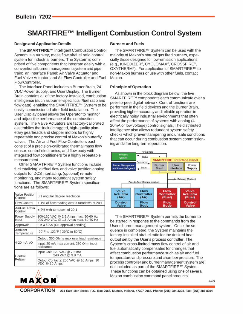
The SMARTFIRE™ Intelligent Combustion ControlSystem is a turnkey, mass flow air/fuel ratio controlsystem for industrial burners. The System is com-prised of five components that integrate easily with aconventional burner management system and pipetrain: an Interface Panel; Air Valve Actuator andFuel Valve Actuator; and Air Flow Controller and FuelFlow Controller.
The Interface Panel includes a Burner Brain, 24VDC Power Supply, and User Display. The BurnerBrain contains all of the factory-installed, combustionintelligence (such as burner-specific air/fuel ratio andflow data), enabling the SMARTFIRE™ System to beeasily commissioned after field installation. TheUser Display panel allows the Operator to monitorand adjust the performance of the combustionsystem. The Valve Actuators are factory-calibratedassemblies that include rugged, high-quality plan-etary gearheads and stepper motors for highlyrepeatable and precise control of Maxon’s butterflyvalves. The Air and Fuel Flow Controllers eachconsist of a precision-calibrated thermal mass flowsensor, control electronics, and flow body withintegrated flow conditioners for a highly repeatablemeasurement.
Other SMARTFIRE™ System functions includefuel totalizing, air/fuel flow and valve position analogoutputs for DCS interfacing, (optional) remotemonitoring, and many redundant system safetyfunctions. The SMARTFIRE™ System specifica-tions are as follows:
Burners and Fuels
The SMARTFIRE™ System can be used with themajority of Maxon’s natural gas fired burners, espe-cially those designed for low-emission applications(e.g., KINEDIZER®, CYCLOMAX®, CROSSFIRE®,OXYTHERM®). For application of SMARTFIRE™ tonon-Maxon burners or use with other fuels, contactMaxon.
Principle of Operation
As shown in the block diagram below, the fiveSMARTFIRE™ components each communicate over apeer-to-peer digital network. Control functions areperformed in the field devices and the Burner Brain,providing higher accuracy and reliable operation inelectrically noisy industrial environments that oftenaffect the performance of systems with analog (4-20mA or low voltage) control signals. The distributedintelligence also allows redundant system safetychecks which prevent tampering and unsafe conditionsthat can occur during combustion system commission-ing and after long-term operation.
The SMARTFIRE™ System permits the burner tobe started in response to the commands from theUser’s burner management system. Once the se-quence is completed, the System maintains thefactory-installed air/fuel ratio for the desired heatoutput set by the User’s process controller. TheSystem’s cross-limited mass flow control of air andfuel automatically compensates for changes thataffect combustion performance such as air and fueltemperature and pressure and chamber pressure. Theprocess controller and burner management system arenot included as part of the SMARTFIRE™ System.These functions can be obtained using one of severalMaxon combustion command panel products.
noitisoPevlaVlortnoC noitulosereergedralugna1.0
lortnoCwolF 1:02fonwodnrutarevognidaerwolffo%1±
oitaRleuF/riAlortnoC 1:02fonwodnruthtiw%2±
ylppuSrewoPtupnI
zH06-05,xamspmA5.2@CAV021-001zH06-05,xamspmA5.1@CAV042-002
slavorppA )gnidneplavorppaEC(ASC&MF
tneibmAerutarepmeT )C°05otC°92-(F°221otF°02-
O/IAm02-4ecnatsiserdaolresuxamsmhO053:tuptuO
tupnimhO052,tnerrucxamAm02:tupnIecnatsiser
lortnoCsyaleR
Am5.7@CAV021:lioCtupnIAm8.3@CAV042
03,spmA01@CAV052:stcatnoCtuptuOspmA01@CDV
Valve Actuator
(Air)
ControlValve
FlowController
(Air)
FlowBody
FlowController
(Fuel)
FlowBody
Valve Actuator
(Fuel)
ControlValve
BurnerBrain
UserInterface
PowerSupply
Burner Management and Flame Safeguard
ProcessControl
SMARTFIRETM
Interface Panel
Firing Rate
Status
Peer-to-Peer Communication Gateway (Option)
Commands
Status
SMARTFIRE™ Intelligent Combustion Control Page 7203
4/10
Electrical Specifications
lortnoCnoitisoPevlaV noitulosereergedralugna1.0
lortnoCwolF 1:02fonwodnrutarevognidaerwolffo%1±
lortnoCoitaRleuF/riA 1:02fonwodnruthtiw%2±
tupnIylppuSrewoP zH06-05,xamspmA5.2@CAV021-001zH06-05,xamspmA5.1@CAV042-002
slavorppA )gnidneplavorppaEC(ASC&MF
erutarepmeTtneibmA )C°05otC°92-(F°221otF°02-
O/IAm02-4ecnatsiserdaolresuxamsmhO053:tuptuO
ecnatsisertupnimhO052,tnerrucxamAm02:tupnI
syaleRlortnoCAm5.7@CAV021:lioCtupnIAm8.3@CAV042
spmA01@CDV03,spmA01@CAV052:stcatnoCtuptuO
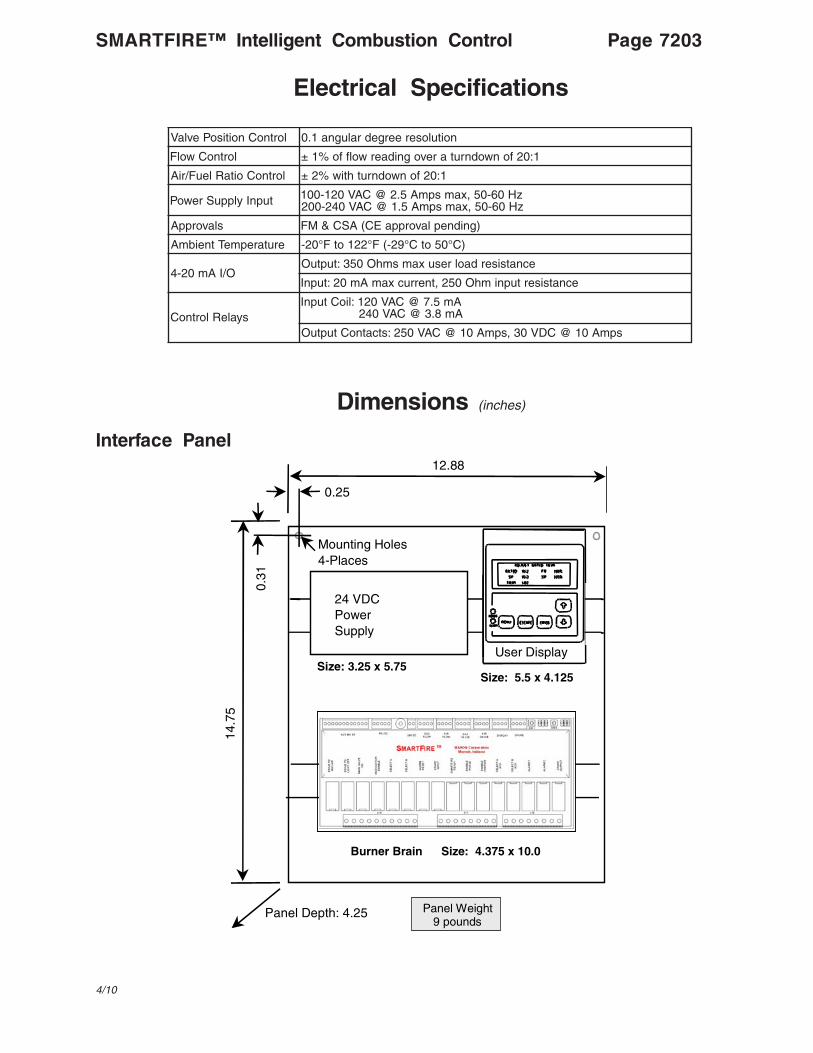
Dimensions (inches)
Interface Panel12.88
14.7
5
Panel Depth: 4.25
0.25
0.31
Mounting Holes4-Places
Panel Weight9 pounds
Size: 3.25 x 5.75Size: 5.5 x 4.125
24 VDCPowerSupply
Burner Brain Size: 4.375 x 10.0
User Display
Page 7204 SMARTFIRE™ Intelligent Combustion Control
Dimensions (inches)
)sehcnI(snoisnemiDydoBwolFriAegnaRwoL egnaRhgiH
xaMegnaRhgiH
erusserP)cw"(porD
wolFniM wolFxaM wolFniM wolFxaM
eziS .D.O htgneLfo.oN.scP
thgieW).sbl(
segnalF s'0001hfcs
s'0001hfcs
s'0001hfcs
s'0001hfcsepyT thgieW
8 36.8 43 1 05 *elgnAdelloR 21 8.2 05 8.3 57 7.4
21 57.21 05 1 86 *elgnAdelloR 61 2.6 111 3.8 761 7.4
61 0.61 46 2 011 *elgnAdelloR 02 8.9 671 2.31 362 7.4
02 0.02 08 2 022 *elgnAdelloR 52 3.51 672 7.02 414 7.4
42 0.42 69 2 052 *elgnAdelloR 82 2.22 993 9.92 995 7.4
82 0.82 69 2 572 *elgnAdelloR 13 3.03 645 9.04 818 7.4
7575-325)377(stcudorPdelloRlateMogacihC*
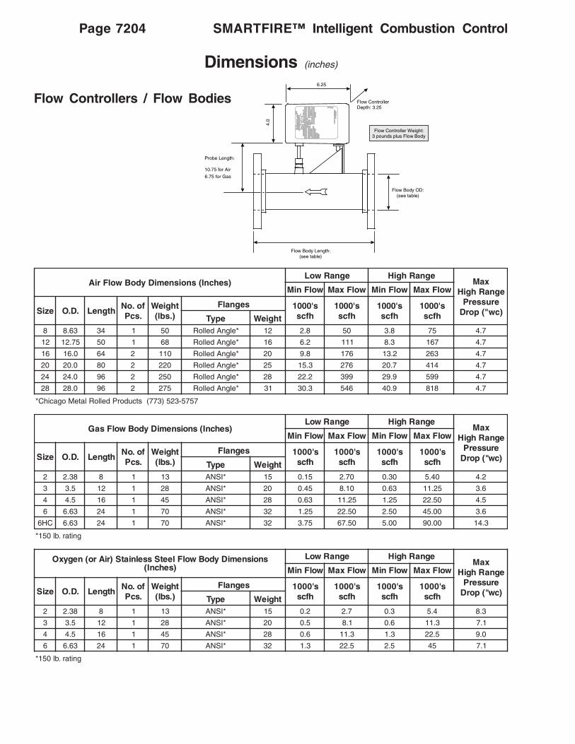
Flow Controllers / Flow Bodies
Flow Controller Weight:3 pounds plus Flow Body
6.25
Probe Length:
10.75 for Air
6.75 for Gas
Flow Body OD:(see table)
Flow Body Length:(see table)
Flow ControllerDepth: 3.25
4.0
)sehcnI(snoisnemiDydoBwolFsaGegnaRwoL egnaRhgiH
xaMegnaRhgiH
erusserP)cw"(porD
wolFniM wolFxaM wolFniM wolFxaM
eziS .D.O htgneLfo.oN.scP
thgieW).sbl(
segnalF s'0001hfcs
s'0001hfcs
s'0001hfcs
s'0001hfcsepyT thgieW
2 83.2 8 1 31 *ISNA 51 51.0 07.2 03.0 04.5 2.4
3 5.3 21 1 82 *ISNA 02 54.0 01.8 36.0 52.11 6.3
4 5.4 61 1 54 *ISNA 82 36.0 52.11 52.1 05.22 5.4
6 36.6 42 1 07 *ISNA 23 52.1 05.22 05.2 00.54 6.3
CH6 36.6 42 1 07 *ISNA 23 57.3 05.76 00.5 00.09 3.41
gnitar.bl051*
snoisnemiDydoBwolFleetSsselniatS)riAro(negyxO)sehcnI(
egnaRwoL egnaRhgiHxaM
egnaRhgiHerusserP
)cw"(porD
wolFniM wolFxaM wolFniM wolFxaM
eziS .D.O htgneLfo.oN.scP
thgieW).sbl(
segnalF s'0001hfcs
s'0001hfcs
s'0001hfcs
s'0001hfcsepyT thgieW
2 83.2 8 1 31 *ISNA 51 2.0 7.2 3.0 4.5 3.8
3 5.3 21 1 82 *ISNA 02 5.0 1.8 6.0 3.11 1.7
4 5.4 61 1 54 *ISNA 82 6.0 3.11 3.1 5.22 0.9
6 36.6 42 1 07 *ISNA 23 3.1 5.22 5.2 54 1.7
gnitar.bl051*

Valve Body Specifications
"4urht"1-snoitacificepSlairetaMydoBevlaV
metI.oN noitpircseD
ylbmessAydoBevlaV
decaFtalFPG decaFdesiaRPG decaFtalFyxO
1 ydoBevlaV norIyarG0003G,RG751AMTSA
leetSnobraCBCW,RG612AMTSA
ssarB00638C.oNSNU26BMTSA
2 metSevlaV 0003G,RG751AMTSA-leetSsselniatS303
3 csiDylfrettuB 00403S.oNSNU403epyT042AMTSA-leetSsselniatS403
4 gnihsuBpoT
00239C.oNSNU485Bdna505B,172BMTSA-eznorB5 gnihsuBmottoB
6 gnihsuBmihSpoT
7 gniR-O
N-anuB notiV8 gniR-O
9 gniR-O
01 wercS leetSsselniatS8-81
11 rehsaW leetSsselniatS403
21 gniRgniniateR leetSsselniatS613
4 89
2
6
1
12
10
11
3
5
7
87
8
SMARTFIRE™ Intelligent Combustion Control Page 7205
4/03
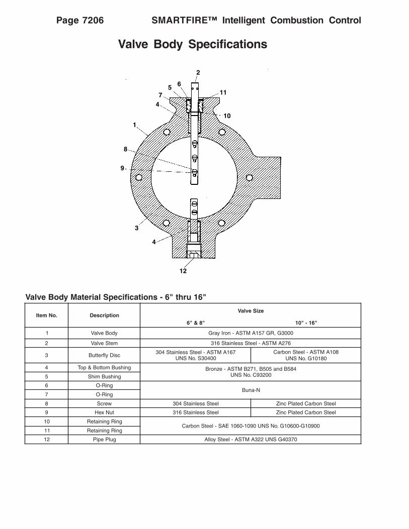
Valve Body Specifications
"61urht"6-snoitacificepSlairetaMydoBevlaV
.oNmetI noitpircseDeziSevlaV
"8&"6 "61-"01
1 ydoBevlaV 0003G,RG751AMTSA-norIyarG
2 metSevlaV 672AMTSA-leetSsselniatS613
3 csiDylfrettuB 761AMTSA-leetSsselniatS40300403S.oNSNU
801AMTSA-leetSnobraC08101G.oNSNU
4 gnihsuBmottoB&poT 485Bdna505B,172BMTSA-eznorB00239C.oNSNU5 gnihsuBmihS
6 gniR-ON-anuB
7 gniR-O
8 wercS leetSsselniatS403 leetSnobraCdetalPcniZ
9 tuNxeH leetSsselniatS613 leetSnobraCdetalPcniZ
01 gniRgniniateR00901G-00601G.oNSNU0901-0601EAS-leetSnobraC
11 gniRgniniateR
21 gulPepiP 07304GSNU223AMTSA-leetSyollA
SMARTFIRE™ Intelligent Combustion ControlPage 7206
2
657
1
4
8
9
11
10
3
4
12
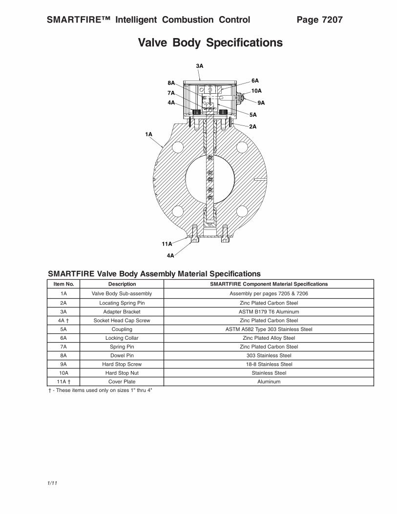
Valve Body Specifications
snoitacificepSlairetaMylbmessAydoBevlaVERIFTRAMS.oNmetI noitpircseD snoitacificepSlairetaMtnenopmoCERIFTRAMS
A1 ylbmessa-buSydoBevlaV 6027&5027segaprepylbmessA
A2 niPgnirpSgnitacoL leetSnobraCdetalPcniZ
A3 tekcarBretpadA munimulA6T971BMTSA
†A4 wercSpaCdaeHtekcoS leetSnobraCdetalPcniZ
A5 gnilpuoC leetSsselniatS303epyT285AMTSA
A6 ralloCgnikcoL leetSyollAdetalPcniZ
A7 niPgnirpS leetSnobraCdetalPcniZ
A8 niPlewoD leetSsselniatS303
A9 wercSpotSdraH leetSsselniatS8-81
A01 tuNpotSdraH leetSsselniatS
†A11 etalPrevoC munimulA
"4urht"1sezisnoylnodesusmetiesehT-†
3A
8A
7A
4A
6A
10A
9A
5A
2A
11A
4A
1A
SMARTFIRE™ Intelligent Combustion Control Page 7207
1/11
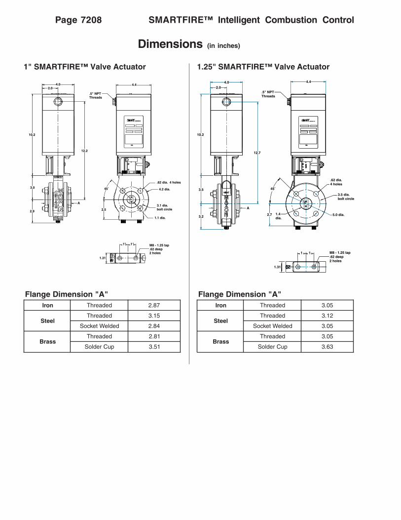
SMARTFIRE™ Intelligent Combustion ControlPage 7208
Dimensions (in inches)
1" SMARTFIRE™ Valve Actuator 1.25" SMARTFIRE™ Valve Actuator
"A"noisnemiDegnalFnorI dedaerhT 78.2
leetSdedaerhT 51.3
dedleWtekcoS 48.2
ssarBdedaerhT 18.2
puCredloS 15.3
"A"noisnemiDegnalFnorI dedaerhT 50.3
leetSdedaerhT 21.3
dedleWtekcoS 50.3
ssarBdedaerhT 50.3
puCredloS 36.3
4.0
10.2
2.0
3.5
A
12.7
3.2
4.4
2.7
3.5 dia.bolt circle
.62 dia.4 holes
5.0 dia.1.4 dia.
M8 - 1.25 tap.62 deep2 holes
1 1
1.31
.5" NPT Threads
45˚
4.0
10.2
2.0
3.0
A
12.2
2.9
4.4
2.5
.62 dia. 4 holes
4.2 dia.
3.1 dia.bolt circle
1.1 dia.
M8 - 1.25 tap.62 deep2 holes
1.31
1" 1"
.5" NPT Threads
45˚
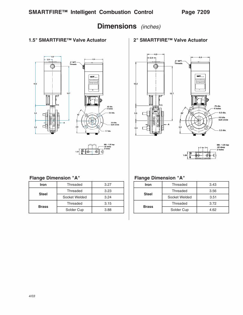
Page 7209SMARTFIRE™ Intelligent Combustion Control
Dimensions (inches)
1.5" SMARTFIRE™ Valve Actuator 2" SMARTFIRE™ Valve Actuator
"A"noisnemiDegnalFnorI dedaerhT 72.3
leetSdedaerhT 32.3
dedleWtekcoS 42.3
ssarBdedaerhT 51.3
puCredloS 88.3
"A"noisnemiDegnalFnorI dedaerhT 34.3
leetSdedaerhT 65.3
dedleWtekcoS 15.3
ssarBdedaerhT 27.3
puCredloS 26.4
4.0
10.2
2.0
3.5
A
12.7
3.2
4.4
2.8
3.9 dia.bolt circle
5.0 dia.
1.7 dia.
M8 - 1.25 tap.62 deep2 holes
1" 1"
.62 dia.4 holes
1.31
.5" NPT Threads
45˚
4.0
10.2
2.0
3.5
A
12.7
3.4
4.4
3.0
4.8 dia.bolt circle
.75 dia.4 holes
6.0 dia.
2.2 dia.
M8 - 1.25 tap.62 deep2 holes
1.69
1 1
1"
45˚
.5" NPT Threads
4/03

Dimensions (in inches)
2.5" SMARTFIRE™ Valve Actuator 3" SMARTFIRE™ Valve Actuator
"A"noisnemiDegnalFnorI dedaerhT 27.3
leetSdedaerhT 76.3
dedleWtekcoS 97.3
ssarBdedaerhT 08.3
puCredloS 72.5
"A"noisnemiDegnalFnorI dedaerhT 38.3
leetSdedaerhT 31.4
dedleWtekcoS 30.4
ssarBdedaerhT 20.4
puCredloS 90.5
4.0
10.2
2.0
4.0
A
13.2
4.2
4.4
3.8 5.5 dia.bolt circle
.75 dia.4 holes
7.5 dia.
2.6 dia.
1.81
M8 - 1.25 tap.62 deep2 holes
1 1
45˚
.5" NPT Threads
4.0
10.2
2.0
4.0
A
13.2
4.2
4.4
6.0 dia. bolt circle
.75 dia.4 holes
7.5 dia.
3.3 dia.
1.81
M8 - 1.25 tap.62 deep2 holes
1 1
3.8
45˚
.5" NPT Threads
SMARTFIRE™ Intelligent Combustion ControlPage 7210
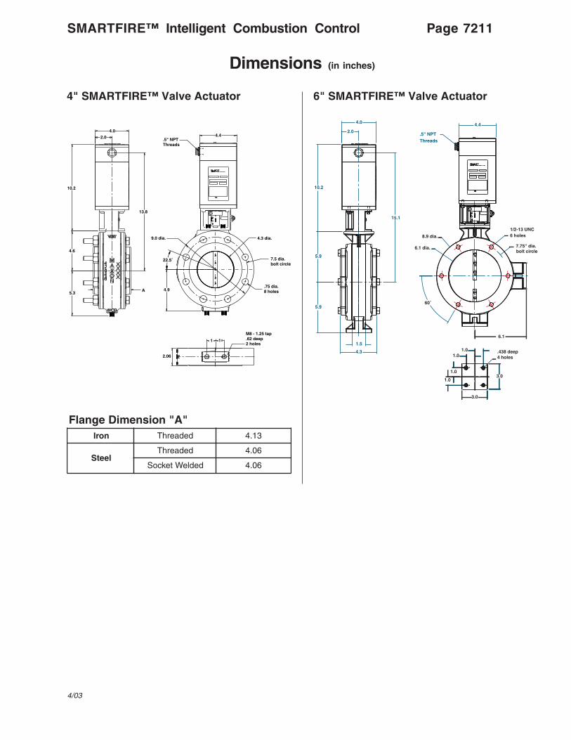
Dimensions (in inches)
4" SMARTFIRE™ Valve Actuator
"A"noisnemiDegnalFnorI dedaerhT 31.4
leetSdedaerhT 60.4
dedleWtekcoS 60.4
10.2
2.0
4.6
A
13.8
5.3
4.4
7.5 dia.bolt circle
.75 dia.8 holes
4.3 dia.
2.06
M8 - 1.25 tap.62 deep2 holes
1 1
4.9
4.0
9.0 dia.
.5" NPT Threads
22.5˚
6" SMARTFIRE™ Valve Actuator
.5" NPTThreads
6.1 dia.
6.1
1/2-13 UNC6 holes
7.75" dia.bolt circle
60˚
4.4
1.01.0
1.0
1.0
.438 deep4 holes
3.0
3.0
5.9
5.9
10.2
15.1
2.0
4.0
1.5
4.3
8.9 dia.
Page 7211SMARTFIRE™ Intelligent Combustion Control
4/03

Dimensions (in inches)
8" SMARTFIRE™ Valve Actuator 10" SMARTFIRE™ Valve Actuator
.5" NPTThreads
60˚
10.25 dia.bolt circle1/2-13 UNC
6 holes
8.0 dia.
11.8dia.
7.6
1.1
3.0
3.01.0
1.0
1.01.0
2.0
4.0
7.4
7.0
10.2
16.2
4.4
1.5
4.4
.438 deep4 holes
.5" NPTThreads
3.0
3.0
1.0
1.0
1.01.0
.438 deep4 holes
18.4
10.2
9.2
7.6
2.56.5
4.4
8.4
3.6
10.0 dia.
13.0 dia.
16.0 dia.
14.2 dia.bolt circle
2.04.0
1.0 dia. 12 holes
Note: Flanges are shipped loose.
SMARTFIRE™ Intelligent Combustion ControlPage 7212

.5" NPTThreads
8.7
10.2
10.2
3.07.6
2.04.0
19.4
4.6
9.5
12.0dia.
1.0 dia.12 holes
16.0 dia.
19.0 dia.
17.0 dia.bolt circle
4.4
.438 de4 holes
Dimensions (in inches)
12" SMARTFIRE™ Valve Actuator 14" SMARTFIRE™ Valve Actuator
.5" NPTThreads
1.01.0
1.01.0
3.0
3.0
4.4
13.2dia.
17.4dia.
18.8 dia.bolt circle
1.1 dia.12 holes
21.0 dia.
5.8
10.5
9.6
11.4
10.2
20.6
2.04.0
3.07.6
.438 deep4 holes
Note: Flanges are shipped loose. Note: Flanges are shipped loose.
Page 7213SMARTFIRE™ Intelligent Combustion Control
6/03

Dimensions (in inches)
16" SMARTFIRE™ Valve Actuator
.5" NPTThreaded
1.01.0
1.0
3.0
3.0
4.4
23.5 dia.
21.2 dia.bolt circle
19.4 dia.
15.0 dia.
1.12 dia.16 holes
11.4
6.6
10.5
12.2
10.2
2.04.0
21.4
3.08.1
.438 deep4 holes
1.0
Note: Flanges are shipped loose.
SMARTFIRE™ Intelligent Combustion ControlPage 7214

INDUSTRIAL COMBUSTION EQUIPMENT AND VALVES
Maxon practices a policy of continuous product improvement. It reserves the right to alter specifications without prior notice.
Page 7200-S-1SMARTFIRE™ Intelligent Combustion Control
General Installation Instructions
4/03
Please read all installation and start-upinstructions prior to working with theSMARTFIRE™ Intelligent Combustion ControlSystem. A view port providing a clear view ofthe entire flame is strongly recommended.
The SMARTFIRE™ Intelligent CombustionControl System accounts for a portion of thetotal combustion system. The sizing andinstallation instructions for other componentssuch as burners, blowers, and regulators canbe found in the corresponding sections of theMaxon catalog.
Do not discard packing material until all partshave been identified. Collect the fiveSMARTFIRE™ components required for controlling aburner (or zone of burners):1. Interface Panel (includes the Burner Brain, User
Interface Terminal, and 24 VDC Power Supply)2. Air Valve Actuator3. Fuel Valve Actuator4. Air Flow Controller (comprised of a sensor probe
and attached electronics in a flow body)5. Fuel Flow Controller (comprised of a sensor
probe and attached electronics in a flow body)
A typical SMARTFIRE™/burner/piping layout isshown below.
Verify that all Maxon System Numbers andBurner Model Identifiers are the same. Becauseall SMARTFIRE™ Systems are pre-configured at thefactory for a given burner system, this installationstep is very important to ensure proper operation.
Typical SMARTFIRE™/Burner/Pipetrain Layout
BurnerAct
Gas
Air and Gas Supplied byConventional Pipe Train
Assembly
FlowAct
Air
Flow
Burner Brain
Interface Panel
UserDisplay
24 VDCSupply
INDUSTRIAL COMBUSTION EQUIPMENT AND VALVES
Maxon practices a policy of continuous product improvement. It reserves the right to alter specifications without prior notice.
Page 7200-S-2 SMARTFIRE™ Intelligent Combustion Control
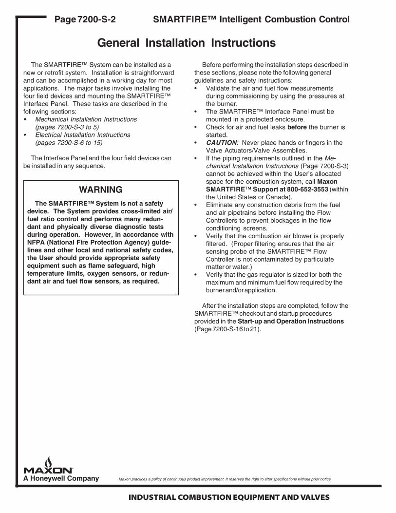
The SMARTFIRE™ System can be installed as anew or retrofit system. Installation is straightforwardand can be accomplished in a working day for mostapplications. The major tasks involve installing thefour field devices and mounting the SMARTFIRE™Interface Panel. These tasks are described in thefollowing sections:• Mechanical Installation Instructions
(pages 7200-S-3 to 5)• Electrical Installation Instructions
(pages 7200-S-6 to 15)
The Interface Panel and the four field devices canbe installed in any sequence.
Before performing the installation steps described inthese sections, please note the following generalguidelines and safety instructions:• Validate the air and fuel flow measurements
during commissioning by using the pressures atthe burner.
• The SMARTFIRE™ Interface Panel must bemounted in a protected enclosure.
• Check for air and fuel leaks before the burner isstarted.
• CAUTION: Never place hands or fingers in theValve Actuators/Valve Assemblies.
• If the piping requirements outlined in the Me-chanical Installation Instructions (Page 7200-S-3)cannot be achieved within the User’s allocatedspace for the combustion system, call MaxonSMARTFIRE™ Support at 800-652-3553 (withinthe United States or Canada).
• Eliminate any construction debris from the fueland air pipetrains before installing the FlowControllers to prevent blockages in the flowconditioning screens.
• Verify that the combustion air blower is properlyfiltered. (Proper filtering ensures that the airsensing probe of the SMARTFIRE™ FlowController is not contaminated by particulatematter or water.)
• Verify that the gas regulator is sized for both themaximum and minimum fuel flow required by theburner and/or application.
After the installation steps are completed, follow theSMARTFIRE™ checkout and startup proceduresprovided in the Start-up and Operation Instructions(Page 7200-S-16 to 21).
WARNINGThe SMARTFIRE™ System is not a safety
device. The System provides cross-limited air/fuel ratio control and performs many redun-dant and physically diverse diagnostic testsduring operation. However, in accordance withNFPA (National Fire Protection Agency) guide-lines and other local and national safety codes,the User should provide appropriate safetyequipment such as flame safeguard, hightemperature limits, oxygen sensors, or redun-dant air and fuel flow sensors, as required.
General Installation Instructions

INDUSTRIAL COMBUSTION EQUIPMENT AND VALVES
Maxon practices a policy of continuous product improvement. It reserves the right to alter specifications without prior notice.
Page 7200-S-3
Mechanical Installation Instructions
SMARTFIRE™ Intelligent Combustion Control
RequirementsWhen installing the SMARTFIRE™ Air and Fuel
Flow Controllers and the Air and Fuel Valve Actua-tors, please note the following:• The arrow on the side of each Flow Controller
should be oriented in the direction of flow.• The Flow Controllers and the Valve Actuators can
be mounted in any orientation.• Refer to the Electrical Installation Instructions
(pages 7200-S-6 to 7200-S-15) for cable andwiring requirements for each of the field devices.Maintain proper wire color code for 24 Volt DCPower and Data Communication Signals.
In cases where replacement Flow Controller airand/or fuel sensor probes (with their attached elec-tronics) need to be installed in their respective flowbodies, loosen the compression fitting sufficiently toinsert the sensor probe and alignment pin into theflow body. The probe assembly should sit flushagainst the flow body’s horizontal mounting flangeand should not be cocked at an angle. The compres-sion fitting is then tightened.
The following piping guidelines for theSMARTFIRE™ field devices ensure that the gas andair flow can be properly measured and controlled.Flow control accuracy is essential for optimum burnerperformance. If the piping requirements outlinedin the Air Piping Guidelines and/or Gas PipingGuidelines cannot be achieved within the spaceallocated for the combustion system, call MaxonSMARTFIRE™ Support at 800-652-3553 (withinthe United States or Canada).
Air Piping GuidelinesAir piping between the combustion blower and the
burner should be constructed using the followingguidelines:• Locate the SMARTFIRE™ Air Valve Actuator at a
maximum distance of 10 blower outlet diametersfrom the combustion blower. This configurationprevents blower pulsation (effects) created by theblower and air piping at low flow rates.
• If Maxon is not supplying the blower, the Usershould contact the blower manufacturer for themaximum recommended distance (for a specificpipe diameter) between the blower outlet and acontrol valve (i.e., the SMARTFIRE™ Air ValveActuator) to prevent Helmholtz effect.
• The SMARTFIRE™ Air Flow Controller is in-stalled downstream of the air valve actuator. Itrequires a total straight piping run of 14 flow bodydiameters (including approximately 4 diametersfor the Flow Controller) to ensure accurate airflow control. See installation schematic on page7200-S-4:
1. A minimum of seven (7) “straight” diameters arerequired upstream of the Air Flow Controller.
Minimum length of pipe =7 x the air flow body diameter
“Straight” diameter piping is defined as samediameter pipe with no elements such as valves,flanges, orifice plates, or bends within the speci-fied pipe length.
2. Exceed the above minimum requirement by asmany straight diameters as space permits (i.e.,maximize the number of straight diametersupstream of the Air Flow Controller). This lengthensures that the air stream can be properlyconditioned and measured by the Air FlowController.
3. A minimum of three (3) “straight” diameters arerequired downstream of the Air Flow Controller.
Minimum length of pipe =3 x the air flow body diameter
• Because the blower is rotational machinery,dampening pads for the blower stand and aflexible (bellows-type or braided stainlesshose) connection from the blower discharge tothe air piping are recommended.
4/03

INDUSTRIAL COMBUSTION EQUIPMENT AND VALVES
Maxon practices a policy of continuous product improvement. It reserves the right to alter specifications without prior notice.
Page 7200-S-4 SMARTFIRE™ Intelligent Combustion Control
Mechanical Installation Instructions
SMARTFIRE™ Air Piping Specification
Note 1: For Maxon blowers, piping distance between the blower and the control valve must not exceed 10 timesthe blower outlet diameter. For non-Maxon blowers, contact the blower manufacturer for the maximumrecommended length for the blower outlet size to prevent Helmholtz effects.
Note 2: Piping diameters should match the Flow Controller’s IDNote 3: Maximize the straight length of Dimension C (space permitting)Note 4: Piping sections dimensioned C and D are customer-supplied
snoisnemiDniartepiPdnarellortnoCwolF
wolFriArellortnoC
eziS
noxaMwolF
rellortnoCN/P
AwolF
rellortnoCDI/DO
)sehcni(
BwolF
rellortnoChtgneL)sehcni(
wolFrellortnoC
egnalFDO/DI
)sehcni(
wolFrellortnoC
egnalFelcriCtloB
)sehcni(
egnalFeloHeziS
rellortnoCwolFegnalF
seloHfo.oNdecapSyllauqE
CmuminiMhtgneL)sehcni(
DmuminiMhtgneL)sehcni(
8 CASFS 24.8/36.8 30.±0.43 26.01/21.8 5.9 604.0 8 95 62
21 CASFS 45.21/57.21 50.±0.05 91.51/91.21 18.31 604.0 21 88 83
61 CASFS 67.51/00.61 60.±0.46 57.91/52.61 31.81 604.0 61 111 84
02 CASFS 67.91/00.02 80.±0.08 57.32/52.02 31.22 604.0 02 931 06
42 CASFS 67.32/00.42 01.±0.69 57.72/52.42 31.62 265.0 02 761 27
82 CASFS 77.72/00.82 01.±0.69 52.23/52.82 5.03 526.0 42 591 48
)7575-325-377(:stcudorPdelloRlateMogacihCrepegnalF
D
See Note 1
Blower
C B
See Note 2
A
From Gas Pipe Train
See Note 2Burner
Controller AssemblyMARTS Flow IREF
Valve MARTS
AssemblyIREF
See Notes 3 & 4 See Note 4

INDUSTRIAL COMBUSTION EQUIPMENT AND VALVES
Maxon practices a policy of continuous product improvement. It reserves the right to alter specifications without prior notice.
Page 7200-S-5SMARTFIRE™ Intelligent Combustion Control
Mechanical Installation Instructions
Gas Piping Guidelines
Gas piping between the fuel train and burnershould be constructed using the following guidelines:• Locate the SMARTFIRE™ Fuel Flow Controller
downstream of the gas regulator and upstream ofthe gas valve actuator.
• The SMARTFIRE™ Fuel Flow Controller requiresa total straight piping run of 14 flow body diam-eters (including approximately 4 diameters for theFlow Controller) to ensure accurate fuel flowcontrol. See installation schematic below:1. A minimum of five (5) “straight” diameters are
required upstream of the Fuel Flow Controller.
Minimum length of pipe =5 x the fuel flow body diameter
“Straight” diameter piping is defined as samediameter pipe with no elements such asvalves, flanges, orifice plates, or bends withinthe specified pipe length.
2. Exceed the above minimum requirement byas many straight diameters as space permits(i.e., maximize the number of straight diam-eters upstream of the Fuel Flow Controller).This length ensures that the gas stream canbe properly conditioned and measured by theFuel Flow Controller.
3. A minimum of five (5) “straight” diameters arerequired downstream of the Fuel FlowController.
Minimum length of pipe =5 x the fuel flow body diameter
Note 1: Piping diameters should match the Flow Controller’s IDNote 2: Maximize the straight length of Dimension C (space permitting)Note 3: Piping sections dimensioned C and D are customer-supplied
snoisnemiDniartepiP
wolFrellortnoC
eziS
yxOwolF
rellortnoCN/P
wolFleuFellortnoC r
N/P
AwolF
rellortnoCDO
)sehcni(
BwolF
rellortnoChtgneL)sehcni(
CmuminiMhtgneL)sehcni(
DmuminiMhtgneL)sehcni(
egnalFISNAgnitaR
)sdnuop(
2 COSSFS CNSFS 83.2 20.±8 21 21 051
3 COSSFS CNSFS 5.3 20.±21 81 81 051
4 COSSFS CNSFS 5.4 20.±61 32 32 051
6 COSSFS CNSFS 36.6 20.±42 23 23 051
epiP04eludehcS
4/03
SMARTFIRE™ Gas Piping Specification
D
See Note 1
Gas Line
CSee Notes 2 & 3
B DSee Note 3
A See Note 1
SMARTFIRE FlowController Assembly
SMARTFIRE Valve Assembly
To Burner

INDUSTRIAL COMBUSTION EQUIPMENT AND VALVES
Maxon practices a policy of continuous product improvement. It reserves the right to alter specifications without prior notice.
Page 7200-S-6 SMARTFIRE™ Intelligent Combustion Control
Electrical Installation Instructions
System Wiring Requirements
The following block diagram indicates the majorsources and destinations of the electrical wiringrequired by the SMARTFIRE™ System. The Systemwiring is divided into the following four categories:• Burner management AC control wiring to/from
the SMARTFIRE™ Burner Brain.• Current loop (4-20 mA) control and monitoring
wiring from a User’s temperature controller and/or DCS system to the SMARTFIRE™ BurnerBrain.
A complete set of wiring schematics de-scribing how SMARTFIRE™ is interfaced to a“typical” burner management system isshown in the following pages.
• Network wiring from the SMARTFIRE™ BurnerBrain to the SMARTFIRE™ Field Devices.
• Power and network wiring between theSMARTFIRE™ Burner Brain and the 24VDCPower and the User Display. These connectionsare factory wired on the SMARTFIRE™ InterfacePanel.
J10
24VDC J1
Gas Flow J7
Spare J2
Display J3
Air Valve J4
Gas Valve J5
Air Flow J6
4-20 mA I/O J9
RS232 J8
J12
J11
s
USER DISPLAY
24VDCSUPPLY
GAS FLOWCONTROLLER
AIR FLOWCONTROLLER
GASVALVE
ACTUATOR
AIRVALVE
ACTUATOR
AIR & GAS FLOWRATE MONITORS
AIR & GAS VALVE POSITION MONITORS
FIRING RATE SOURCE
User 4-20mA Inputs & OutputsSMARTFIRE™ Interface Panel
SMARTFIRE™ Field Devices(Network Cabling)
BURNER START/STOPCONTROL SOURCE
(120VAC RELAYCOIL DRIVES)
BURNER START/STOP CONTROL MONITOR
(120VAC SPSTRELAY CONTACTS)
User Burner Management System
BU
RN
ER
BR
AIN
Relay In
pu
tsR
elay Ou
tpu
tsR
elay Ou
tpu
ts
RS232 J8

INDUSTRIAL COMBUSTION EQUIPMENT AND VALVES
Maxon practices a policy of continuous product improvement. It reserves the right to alter specifications without prior notice.
TO: 200
15
15
19
19
18
18
17
19
18
2
2
17 2
4
4
8
3
4
4
5
2
17
13 13
2
2
1312
4 4
Lockout Interlocks
Indicates TemperatureControl Enabled
IndicatesPurge Complete
IndicatesSystem Purging
Lockout Interlocks
Indicates InterlocksProven
To Line 302(SMARTFIRE J10-2)
Continued on Line 200
To Line 302(SMARTFIRE J10-3)
To Line 303(SMARTFIRE J10-5)
Proof ofClosure
20
15
14
12
Control PanelPower
Neutral
LockoutInterlocks
(L1)
13
4
Request forHeat
6
L2
7
HoneywellFlame SafeguardRM7800E-1010
FSG106
J11-1
See Line 307
J11-2
SMARTFIRE Ready
120/1/60
➤
➤
➤
Purging
LT109X1 X2
A
4
Blocking ValveVCS-1
BV303
116
115
114
113 7 8
4111
112
110
87Main Valve
VCS-1
MV301
15 15
2
16
Temperature ControlEnabled
LT115X1 X2
G
Purge Complete
LT112X1 X2
B
102 5Combustion Air Pressure Switch
CAP102
RemoteBurner Start
CR3087 4
109
108
107
106
105
104
103
Customer Interlocks #2
Customer Interlocks #3
Customer Interlocks #1
9
1
1
101
100OFF ON
SS1003 4
887 766Low Gas
Pressure Switch
LGP102
High GasPressure Switch
HGP102
10 109 11
InterlocksProven
LT106X1 X2
W
10 AMP
FU100
Control PanelPower On
LT100X1 X2
G2
2
High TemperatureLimit
HTL400
2 3
Jumper all unused limits and interlocks
Field wiring shown forblock and bleed valve
arrangement
Page 7200-S-7SMARTFIRE™ Intelligent Combustion Control
Electrical Installation Instructions
4/03
Typical SMARTFIRE™ Wiring Schematic

INDUSTRIAL COMBUSTION EQUIPMENT AND VALVES
Maxon practices a policy of continuous product improvement. It reserves the right to alter specifications without prior notice.
Page 7200-S-8
Electrical Installation Instructions
SMARTFIRE™ Intelligent Combustion Control
Typical SMARTFIRE™ Wiring Schematic (Continued)
29 29 2
25
22
22 21
25
20 23
25 26
2
2
Remote Alarm
2
Main Valves9
Provides True Indication of Pilot Status
UVD208
White (L2)
White (S)
SMARTFIRE Enable Ignition
(DDL Cable)
Keyboard DisplayModule
See Line 309
J11-5 J11-6
Flame Detector22G
F
Yellow
Blue
Interrupted Pilot
(15 sec.)
Ignition(10 sec.)
Low FirePosition
5
18
21
8
SMARTFIRE Enable Purge
See Line 308
J11-3 J11-4Alarm
Continued From Line 116
High FirePosition
19
RM7800E1010FSG106
HoneywellFlame Safeguard
3
Flame Detector
IndicatesPilot is On
HoneywellSelf Checking Flame DetectorC7061A-1012
Pilot Valve
Indicates an AlarmCondition Exists
ShutterThis device is externally mounted to the
nclosure door, and is ated for NEMA 4 nvironment
Ignition cable to the spark electrode must be run in separate conduit
Wire to the detector should be #14AWG Type 600V insulated wire or equal. Wire must not be in the same conduit with power wiring.
29 2
CR211A B
2
XFMR203
28
GND
27
24
Pilot Valve
PV206
25 2
Pilot On
LT205X1 X2B
SP204
CR2117 4
2
Alarm
LT201X1 X2
R
Jumper
23
23
2
2
To enable shut-off valve power
CR
Spark IgnitionTransformer
54
123
Spark Plug
Spark IgnitionTransformer
205

INDUSTRIAL COMBUSTION EQUIPMENT AND VALVES
Maxon practices a policy of continuous product improvement. It reserves the right to alter specifications without prior notice.
Page 7200-S-9
Electrical Installation Instructions
SMARTFIRE™ Intelligent Combustion Control
7/08
Typical SMARTFIRE™ Wiring Schematic (Continued)
SMARTFIREUser Interface
MAXON P/N 59829 cable used for connections to valve actuators and Flow Controllers. Apply color code: +24VDC, White/OrangeGND, OrangeData A, White/BlueData B, Blue
2
2
SMARTFIREGas FlowController
SMARTFIREGas ValveActuator
SMARTFIREAir FlowController
SMARTFIREAir ValveActuator
2
2
1AIN0+2
43
AIN0-
AIN1-AIN1+
65
7AOUT1+AOUT0-AOUT0+
J91
217
2 Relay ret
SMARTFIRE BURNER BRAIN
LN
PE
120 VAC
(+)(+)
(-)(-)
24 VD
C
9
1110
AOUT3+AOUT2-AOUT2+
12
21
RXTX
AOUT3-
43
5
CTSRTSCOM
1+24VDC
Reservedfor futureSMARTFIREuse
12
2
GND
GND+24VDC
412GND
+24VDCDATA BDATA A 3
3
14
+24VDC
DATA ADATA B
2
43
GND
DATA BDATA A
J10
(Inpu
t rel
ay c
oils
ref t
o re
lay
ret)
J8J1
3
5
4
18
32
19
6
7
8
9
33
Select B
Select A
Modulation enable
Main valve on
Drive to light off
Spare Input
Alarm Reset
J7J5
J6
10
1
2
3
4
13
4
20
12
Spare Input
SMARTFIRE ready
SMARTFIRE ready ret
Enable purge
Enable purge ret
Drive to max air AOUT1- 8
4
From line 215
300
301
32
BV303
12
4
4 10303
4
305
304
VCS-2Blocking Valve
Contacts closewhen valve starts open
307
306
308
302
To Line 201
To Line 104
From Line 201
From Line 104
From Line 115
From Line 112
From Line 109
SMARTFIREAlarm Reset
PB7053 4
GND+24VDC
DATA A
SHLDDATA B
123
GND+24VDC
DATA A
1
32GND
DATA A
+24VDC4DATA B
4
21
GND+24VDCDATA B
43
DATA BDATA A
CR2CR3
CR1
CR5
CR6CR4
J4J3J11
(N.0
. out
put r
elay
con
tact
pai
rs)
J2
5
6
7
8
21
22
9
10
114
Select B ack ret
Select B ack
Alarm 1
Select A ack ret
Enable ignition ret
Select A ack
Enable ignition
SW
2
J12
(N.0
. out
put r
elay
con
tact
pai
rs)
12
13
14
4
34
35
16
15
Spare output ret
Spare output
Alarm 1 ret
Alarm 2
Alarm 2 ret
SW
1
310
309
4
312
311
34
35
2
2Alarm 2
LT713X1 X2
R
313
315
314
Alarm 1
LT712X1 X2
R
4
316
To Line 204
From Line 205
Reserved for future SMARTFIRE use
4/20 mA output, mass flow gas
4/20 mA output, mass flow air
4/20 mA output, gas valve position
4/20 mA output, air valve position
4/20 mA temperature control input
+24VDCGNDDATA A
SHLDDATA B
+24VDCGNDDATA ADATA BSHLD+24VDCGNDDATA ADATA BSHLD+24VDCGNDDATA ADATA BSHLD
Optional Telephone GatewayMaxon P/N 1055838
Split Ferrite, 2-turns, line/neutral, Steward #28A2024-OA
Data BData A
RJ11 To Telephone Service
120VAC to 24VDC Supply
Indicates external wiring
Indicates terminals and wiring in Maxon Control Panel
OrangeWeidmullerBLA 5.08Series Connector
Split
Fer
rite,
1-tu
rn
Stew
ard
#28A
2024
-OA
Flow
Con
trol N
etw
ork

INDUSTRIAL COMBUSTION EQUIPMENT AND VALVES
Maxon practices a policy of continuous product improvement. It reserves the right to alter specifications without prior notice.
Page 7200-S-10
Electrical Installation Instructions
SMARTFIRE™ Intelligent Combustion Control
Field Device Wiring Requirements
A four-conductor cable with an outer shield isrequired between the SMARTFIRE™ Burner Brain andeach of the four SMARTFIRE™ field devices (four fieldcables are required, one for each field device). A fifthcable of the same type is provided (pre-wired) with theInterface Panel. It connects the Burner Brain to theUser Interface Terminal. An optional sixth cable can berun for connection to a remote display or to connect toa telephone gateway for remote monitoring by Maxonfield support personnel.
The recommended cable can be purchased fromMaxon (P/N 59829) in a 500-foot spool, or it can besupplied in longer lengths (Connect-Air P/N W22P-1005)by contacting the following manufacturer.
Connect-Air International, Inc.4240 “B” Street NWAuburn, Washington 98001Phone: 800-247-1978
The shields of each field cable should be terminatedjust as the cable enters the enclosure that houses theInterface Panel. Shield wire length should not exceed2 inches.
Maxon recommends all SMARTFIRE™ field devicecables be routed through a dedicated conduit or at leastone that carries only low voltage, instrumentationsignals.
Typically, flex conduit is used at each field device.The flex conduits feed a common steel conduit or cabletray that is run to the combustion panel. TheSMARTFIRE™ control cable conduit(s) should notshare the same conduit with any AC wiring or be inclose proximity to the burner ignition cable. All wiringshould be done in accordance with all applicablelocal and national electric codes.
The maximum total length of the recommendedMaxon cable (P/N 59829) must be:• Less than a total length of 1100 feet• No single cable run to a SMARTFIRE™ Flow
Controller, remote User Display Terminal, or DigitalGateway greater than 300 feet
• No single cable run to a SMARTFIRE™ ValveActuator greater than 100 feet.
If any single cable run to a SMARTFIRE™ ValveActuator exceeds 100 feet in length but is less than300 feet, Belden Cable #3086A should be ordered.Belden product distribution information is available at1-800-BELDEN-1 or www.belden.com.
If a single cable run to any SMARTFIRE™ devicemust exceed 300 feet, call the Maxon ProductSupport Team at 1-800-652-3553 within the UnitedStates or Canada.
The Burner Brain diagram on the following pageshows all input/output terminations to the User’sburner management system and field device cableterminations for the SMARTFIRE™ Valve Actuatorsand Flow Controllers. The tables on pages 7200-S-12 through 7200-S-15 explain the function of allinputs and outputs and network wiring color code.
It is the responsibility of the User to ensurethat Maxon’s SMARTFIRE™ Burner Brain iswired correctly to the proper burner start-upsequencing logic and combustion safety inter-locks as required by local and national safetycodes.
The User’s burner management system andall related electrical control drawings thatincorporate Maxon’s SMARTFIRE™ CombustionControl System should be reviewed by qualifiedpersonnel knowledgeable in all relevant safetyand industrial combustion requirements.
Maintain the integrity of the MAXON enclosureby using NEMA 4X or IP66 rated dust- and water-tight electrical connectors. Use cable-sealing gripsand strain-relief loops for any cord or cable. Useinternal sealing materials on all conduit connec-tions. Moisture can have a harmful effect ondevice internals if permitted to enter through wiringconnectors. Ensure that the device connection isnot at a low point of the conduit to avoid conden-sation run-off into the housing; install a drip loop ifnecessary. Make sure that the access cover plateis in place and securely fastened. All cover screwsshould be tightened using an alternate cross-corner tightening pattern. Cover screws should bechecked periodically to ensure adequate sealingprotection.

INDUSTRIAL COMBUSTION EQUIPMENT AND VALVES
Maxon practices a policy of continuous product improvement. It reserves the right to alter specifications without prior notice.
Page 7200-S-11
Electrical Installation Instructions
SMARTFIRE™ Intelligent Combustion Control
Burner Brain Interconnect Diagram
4/03
RELAY RET
DRIVE TO MAX AIR
DRIVE TO LIGHTOFF
MAIN VALVE ON
MODULATION ENABLE
SELECT A
SELECT B
ALARM RESET
SPARE INPUT
N/C
SMARTFIRE READY
SMARTFIRE READY RET
ENABLE PURGE
ENABLE PURGE RET
ENABLE IGNITION
ENABLE IGNITION RET
SELECT A ACK
SELECT A ACK RET
SELECT B ACK
SELECT B ACK RET
ALARM 1
ALARM 1 RET
ALARM 2
ALARM 2 RET
SPARE OUTPUT
SPARE OUTPUT RET
AIN0 +AIN0 –AIN1 +AIN1 –AOUT0 +AOUT0 –AOUT1 +AOUT1 –AOUT2 +AOUT2 –AOUT3 +AOUT3 –
+24VDCGNDDATA ADATA B
+24VDCGNDDATA ADATA B
+24VDCGNDDATA ADATA B
+24VDCGND
TXRXCTSRTSCOM
+24VDCGNDDATA ADATA B
+24VDCGNDDATA ADATA B
+24VDCGNDDATA ADATA B
123456789
101112
12345
12
1234
1234
1234
1234
1234
1234
1
2
3
4
5
6
7
8
9
10
1
2
3
4
5
6
7
8
9
10
11
12
13
14
15
16
J10
24VDC J1
Gas Flow J7
Spare J2
Display J3
Air Valve J4
Gas Valve J5
Air Flow J6
4-20 ma I/O J9
RS232 J8
J12
J11
Relay Inputs
Relay O
utputsR
elay Outputs
BU
RN
ER
BR
AIN
mA

INDUSTRIAL COMBUSTION EQUIPMENT AND VALVES
Maxon practices a policy of continuous product improvement. It reserves the right to alter specifications without prior notice.
Page 7200-S-12 SMARTFIRE™ Intelligent Combustion Control
Electrical Installation Instructions
)CAV021(stupnIyaleRemaNlangiS lanimreT noitcnuFlangiS
TERYALER 1-01J .stupniyaler™ERIFTRAMSCAV021llarofnruteR
RIAXAMOTEVIRD 2-01J dnanoitisopnepollufaotevlavriastinepoot™ERIFTRAMSsdnammoC.wolfriaskcehc
FFOTHGILOTEVIRD 3-01J snigebdnaseerged5taevlavleufstinoitisopot™ERIFTRAMSsdnammoC.tniopteswolfgnitratsderiuqerehtotwolfriagnillortnoc
NOEVLAVNIAM 4-01J .nepootnugebevahsevlavffo-tuhsleufehttaht™ERIFTRAMSsmrofnI.etargnirifgnitratsderiuqerehttadelbanenehtsilortnocoitarleuf/riA
ELBANENOITALUDOM 5-01J gnirifAm02-4ehtnodesabetargniriffonoitaludom™ERIFTRAMSselbanE)2-9J,1-9J(tupnietar
ATCELES 6-01J renruBehtnidellatsnisevrucoitarleuf/ria™ERIFTRAMSeerhtfoenostceleS:swollofsaedamerasnoitcelesesehT.lortnoc™ERIFTRAMSselbasidroniarB
otdeilppaegatlovonhtiwdetcelessievruCoitaRleuF/riAgnitarepOtluafeD-.tupnirehtie
.CAV0taBtceleSdnaCAV021taAtceleShtiwdetcelessi1.oNevruC-
.CAV021taBtceleSdnaCAV0taAtceleShtiwdetcelessi2.oNevruC-
.stupnihtobnoCAV021htiwdetcelessielbasidlortnoc™ERIFTRAMS-
.hctiwsenaporp/riaenil-nonagniruddesuebdluownoitcnufelbasidlortnocehT.pu-tratsgniruddilavnisidnammoclanoitareposihT
BTCELES 7-01J
TESERMRALA 8-01J dnariadna,smralatimil-leufdnaria-dehctal,snoitidnocnwodtuhsllasteseRehtnehwdemrofrepsinoitcnuftesersihT.smralakcehcwolfleuf
.CAV021ot0morfnoitisnartasesnesniarBrenruB™ERIFTRAMS
TUPNIERAPS 9-01J .esuerutufrofdevreseR
NOITCENNOCON 01-01J .noitcennocoN
SMARTFIRE™ Input/Output Signal Descriptions

INDUSTRIAL COMBUSTION EQUIPMENT AND VALVES
Maxon practices a policy of continuous product improvement. It reserves the right to alter specifications without prior notice.
Page 7200-S-13
Electrical Installation Instructions
SMARTFIRE™ Intelligent Combustion Control
4/03
)CAV021(stuptuOyaleRemaNlangiS lanimreT noitcnuFlangiS
ERIFTRAMS MT YDAER 1-11J :deifsitaserasnoitidnocgniwollofehtpu-tratstasetacidnitcatnoctuptuodesolC
ERIFTRAMSllA- MT .ylreporpgninoitcnuferastnenopmoc.noitisopybdnatsriehtnierasevlavlortnoC-
ERIFTRAMS- MT .dnammocria"mumixam-ot-evird"atpeccaotydaersimetsyS
tnemeganamrenrubehtybdeneposievlavsagniamehtdnatilsitolipehtretfAronoitidnocnwodtuhsasselnudesolcsniamertcatnoctuptuosiht,metsys
.detcetedsieruliaf
ehtyolpmetsumerawdrahtnemeganamrenrubdedivorp-resUERIFTRAMS" MT gninnurdnapu-tratsasastcatnoctuptuo"ydaeR
.evissimrep
ERIFTRAMS MT TERYDAER 2-11J
EGRUPELBANE 3-11J ERIFTRAMSehtretfaecneuqespu-tratsehtgnirudsesolctcatnoctuptuO MT riaehtfotnecrep05nahtretaergwolfriadnanoitisopnepollufehtsehcaerevlav
.rellortnoCwolFssaMriaehtybderusaemsierifhgihtaderiuqerwolfmumixam
ERIFTRAMSlitnudesolcniamerstcatnoC MT litnuronoitidnocefasnunastceted.resUrometsystnemeganamrenrubehtybyllanretxenwodtuhssirenrubeht
TEREGRUPELBANE 4-11J
NOITINGIELBANE 5-11J ERIFTRAMSnehwsetacidnitcatnoctuptuodesolC MT "tratserif-wol"anisigniwollofehtretfaecneuqespu-tratsehtgnirudesolcstcatnocehT.noitidnoc
:deveihcaerasnoitidnoc
dehsilpmoccaneebsahwolfriagnitratS-)tluafedsiseerged5(noitisopgnitratsstinisievlavlortnocleuF-
tneserptonsierifhgihrofderiuqerwolfehtfoht02/1fossecxeniwolfsaG-.)stsixekaelleufelbaicerppaon,.e.i(
ERIFTRAMSlitnudesolcsniamertcatnoC MT litnuronoitidnocefasnunastceted.metsystnemeganamrenrubroresUehtybnwodtuhsyllanretxesirenrubeht
TERNOITINGIELBANE 6-11J
KCA"A"TCELES 7-11J evrucoitarleuf/riahcihwegdelwonkcasnoitanibmoctcatnoctuptuonepo/esolCERIFTRAMSfirodetcelessi MT dnaAtceleSotrefeR.delbasidneebsahlortnoc
.snoitanibmoctcatnocrofstupniBtceleSTERKCA"A"TCELES 8-11J
KCA"B"TCELES 9-21J
TERKCA"B"TCELES 01-21J
1MRALA 11-21J ERIFTRAMSehttahtsetacidnitcatnoctuptuodesolC MT wolfadetcetedmetsySdnadnammoC"otrefeR.eruliafecivedro,nwodtuhs,noitidnocmralatset
.snoitidnocmralallafotsilarofnoitcnuF"yalpsiDTER1MRALA 21-21J
2MRALA 31-21J ebdluohstahtnoitidnocmralalevelrewolasetacidnitcatnoctuptuodesolCdnadnammoC"otrefeR.noitarepometsysreporperusneotdetagitsevni
.snoitidnocmralallafotsilarofsnoitcnuF"yalpsiDTER2MRALA 41-21J
TUPTUOERAPS 51-21JERIFTRAMSerutufrofdevreseR MT .esu
TERTUPTUOERAPS 61-21J
SMARTFIRE™ Input/Output Signal Descriptions

INDUSTRIAL COMBUSTION EQUIPMENT AND VALVES
Maxon practices a policy of continuous product improvement. It reserves the right to alter specifications without prior notice.
Page 7200-S-14 SMARTFIRE™ Intelligent Combustion Control
Electrical Installation Instructions
stuptuO/stupnIAm02ot4emaNlangiS lanimreT noitcnuFlangiS
STUPNI
)ETARGNIRIF(+0NIA 1-9J sasitnioptesetargnirifs'renrubehtsehsilbatsetahtlangistupniAm02ot4A:swollof
s'renrubehtfotnecrep001fotnioptesastneserperlangiselacs-lluf,Am02A-.yticapactaehdetarmumixam
.yticapactaehmuminims'renrubehtstneserperlangisAm4A-
.langisetargnirifehtsedivorpyllacipytrellortnocerutarepmets'resUehT
)ETARGNIRIF(-0NIA 2-9J
)ESUERUTUF(+1NIA 3-9J
.esuerutufrofdevreseR)ESUERUTUF(-1NIA 4-9J
STUPTUO
)WOLFSAG(+0TUOA 5-9J ybderusaemwolfssamriadnasagehtetacidnislangistuptuoAm02ot4ehTERIFTRAMSeht MT :langishcaeroF.srellortnoCwolF
.rellortnoCwolFevitcepserehtfowolfelacs-llufehtstneserperAm02-
.wolfonstneserperAm4-
ERIFTRAMSehtmorfdetalosierastuptuohtoB MT secruosdnaylppusCDV42+.tnerruc
)WOLFSAG(-0TUOA 6-9J
)WOLFRIA(+1TUOA 7-9J
)WOLFRIA(-1TUOA 8-9J
+2TUOA)NOITISOPEVLAVSAG(
9-9J sasnoitisopevlavriadnasagehtetacidnislangistuptuoAm02ot4ehTERIFTRAMSehtybderusaem MT :langishcaeroF.srotautcAevlaV
.seerged001fonoitisopevlavasetacidniAm02-
.seerged0fonoitisopevlavasetacidniAm4-
hcaE.seerged08fonoitisopmumixamaotnepoyltnerrucsrotautcAevlaVehTERIFTRAMSehtmorfdetalosisilangis MT dnaylppusCDV42+s'metsyS
.tnerrucsecruos
-2TUOA)NOITISOPEVLAVSAG(
01-9J
+3TUOA)NOITISOPEVLAVRIA(
11-9J
-3TUOA)NOITISOPEVLAVRIA(
21-9J
ecafretnI232-SRemaNlangiS lanimreT noitcnuFlangiS
XT 1-8J ERIFTRAMS232-SRerutufrofdevreseR MT dna,noitarugifnoc,gnirotinom.sesoprupcitsongaid
XR 2-8J
STC 3-8J
STR 4-8J
MOC 5-8J
INDUSTRIAL COMBUSTION EQUIPMENT AND VALVES
Maxon practices a policy of continuous product improvement. It reserves the right to alter specifications without prior notice.
Page 7200-S-15SMARTFIRE™ Intelligent Combustion Control
Electrical Installation Instructions
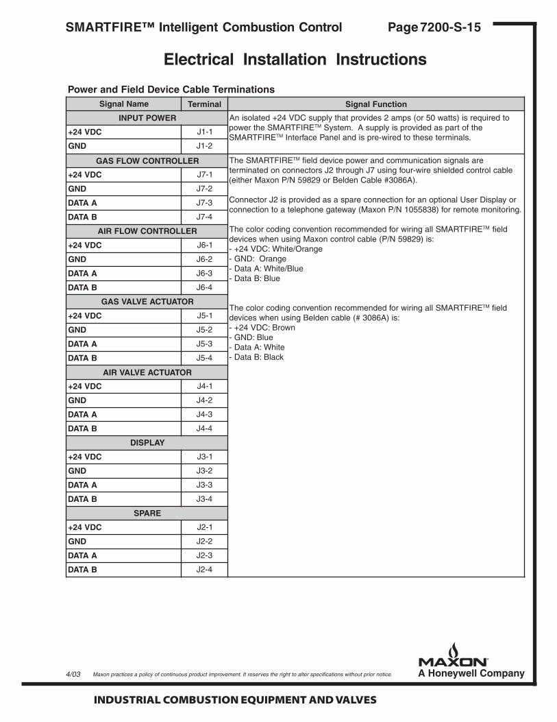
snoitanimreTelbaCeciveDdleiFdnarewoPemaNlangiS lanimreT noitcnuFlangiS
REWOPTUPNI otderiuqersi)sttaw05ro(spma2sedivorptahtylppusCDV42+detalosinAehtrewop ERIFTRAMS MT ehtfotrapsadedivorpsiylppusA.metsyS
ERIFTRAMS MT .slanimretesehtotderiw-erpsidnalenaPecafretnICDV42+ 1-1J
DNG 2-1J
RELLORTNOCWOLFSAG ehT ERIFTRAMS MT eraslangisnoitacinummocdnarewopeciveddleifelbaclortnocdedleihseriw-ruofgnisu7Jhguorht2Jsrotcennocnodetanimret
.)A6803#elbaCnedleBro92895N/PnoxaMrehtie(
royalpsiDresUlanoitponarofnoitcennocerapsasadedivorpsi2JrotcennoC.gnirotinometomerrof)8385501N/PnoxaM(yawetagenohpeletaotnoitcennoc
llagniriwrofdednemmocernoitnevnocgnidocrolocehT ERIFTRAMS MT dleif:si)92895N/P(elbaclortnocnoxaMgnisunehwsecived
egnarO/etihW:CDV42+-egnarO:DNG-
eulB/etihW:AataD-eulB:BataD-
llagniriwrofdednemmocernoitnevnocgnidocrolocehT ERIFTRAMS MT dleif:si)A6803#(elbacnedleBgnisunehwsecived
nworB:CDV42+-eulB:DNG-
etihW:AataD-kcalB:BataD-
CDV42+ 1-7J
DNG 2-7J
AATAD 3-7J
BATAD 4-7J
RELLORTNOCWOLFRIA
CDV42+ 1-6J
DNG 2-6J
AATAD 3-6J
BATAD 4-6J
ROTAUTCAEVLAVSAG
CDV42+ 1-5J
DNG 2-5J
AATAD 3-5J
BATAD 4-5J
ROTAUTCAEVLAVRIA
CDV42+ 1-4J
DNG 2-4J
AATAD 3-4J
BATAD 4-4J
YALPSID
CDV42+ 1-3J
DNG 2-3J
AATAD 3-3J
BATAD 4-3J
ERAPS
CDV42+ 1-2J
DNG 2-2J
AATAD 3-2J
BATAD 4-2J
4/03

INDUSTRIAL COMBUSTION EQUIPMENT AND VALVES
Maxon practices a policy of continuous product improvement. It reserves the right to alter specifications without prior notice.
Page 7200-S-16 SMARTFIRE™ Intelligent Combustion Control
Start-up and Operation Instructions
Checkout before Start-up
After the SMARTFIRE™ System has been in-stalled and before power is applied, follow thecheckout procedure listed below:1. Verify that all Maxon system numbers and burner
model identifiers on the device labels are thesame. Because all SMARTFIRE™ systems arepreconfigured at the factory for a specific burnerconfiguration, this verification is very important.It ensures that the proper components areinstalled.
2. Verify the Air Flow Controller and Air ValveActuator are installed in the air pipetrain and theGas Flow Controller and Gas Valve Actuator areinstalled in the gas pipetrain.
3. Verify the proper connection of theSMARTFIRE™ READY output contact to the start-up and running interlock of the User’s burnermanagement system. With no AC power appliedto the SMARTFIRE™ Interface Panel, theSMARTFIRE™ READY output should provide anopen contact to the burner management permis-sive circuit.
4. Verify that all other required terminations havebeen made at the Burner Brain.
5. Verify the connections and color coding conven-tion on all control cable wiring at eachSMARTFIRE™ field device and the Burner Brain.
6. On the Interface Panel with power off, measurethe resistance between earth ground and each ofthe four signals wired to each field device: 24VDC, GND, Data-A, and Data-B. The resistanceshould indicate an open circuit (i.e., a resistancevalue of several Mega-Ohms). If the resistancevalue does not indicate an open circuit, it is likelythat there is a short circuit in the cabling betweenthe field devices and the Burner Brain. Discon-nect each cable and determine where the shortcircuit exists.
7. Perform all required prestart-up checkout proce-dures for the installed burner, pipetrain, and theburner management system.
Once these checks have been completed, theSMARTFIRE™ System is ready to operate in con-junction with the User’s installed burner managementsystem.
Start-up Procedure
During start-up, the SMARTFIRE™ Systemresponds to commands supplied by the burnermanagement system by moving its Air and Gas ValveActuators to appropriate positions and closingseveral output contacts to acknowledge specificconditions such as “maximum combustion air” and“low fire start” conditions.
Note: The SMARTFIRE™ System does notreplace, inhibit, or interfere with any of thesafety functions provided by the User’sflame relay or burner management system.
During the start-up sequence outlined below, if theUser Display shows an alarm indication, referencethe Troubleshooting section of these instructions(Page 7200-S-23) for appropriate action.
If the start-up sequence does not proceed asexpected, check if the required SMARTFIRE™ inputor output is powered and properly connected to theburner management system.
The following burner start-up procedure is drivenby the User’s burner management system:1. Apply 120VAC power to the 24VDC Supply of the
SMARTFIRE™ Interface Panel. After power isapplied, the User Display reads, “System Initializ-ing.” All SMARTFIRE™ output contacts areopened while the System performs initializationand self-diagnostic tasks. The System will closethe SMARTFIRE™ READY contact after approxi-mately 20 seconds if all the following conditionsare met:• The SMARTFIRE™ Flow Controllers and
Valve Actuators are communicating properly;• A fuel leak test passes (i.e., fuel flow less
than 1/20th the burner’s flow at high fire);• Both Valve Actuators are in their pre-defined
standby positions: and• The combustion-related data in the Burner
Brain are correct.
When the System completes initialization suc-cessfully, the User Display reads “SMARTFIRE™Ready ON, Waiting for Dr to Max” with no alarmconditions displayed. The SMARTFIRE™System is now waiting for the burner manage-ment command to drive to a maximum air condi-tion for purging.
INDUSTRIAL COMBUSTION EQUIPMENT AND VALVES
Maxon practices a policy of continuous product improvement. It reserves the right to alter specifications without prior notice.
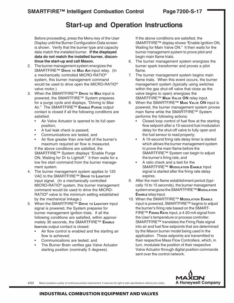
Before proceeding, press the Menu key of the UserDisplay until the Burner Configuration Data screenis shown. Verify that the burner type and capacitydata match the installed burner. If the displayeddata do not match the installed burner, discon-tinue the start-up and call Maxon.
2. The burner management system energizes theSMARTFIRE™ DRIVE TO MAX AIR input relay. (Ina mechanically controlled MICRO-RATIO®
system, this burner management commandwould be used to drive open the MICRO-RATIO®
valve motor.)3. When the SMARTFIRE™ DRIVE TO MAX input is
powered, the SMARTFIRE™ System preparesfor a purge cycle and displays, “Driving to MaxAir.” The SMARTFIRE™ ENABLE PURGE outputcontact is closed if all the following conditions aresatisfied:• Air Valve Actuator is opened to its full open
position;• A fuel leak check is passed;• Communications are tested, and• Air flow greater than one-half of the burner’s
maximum required air flow is measured.If the above conditions are satisfied, theSMARTFIRE™ System displays “Enable PurgeON, Waiting for Dr to Lightoff.” It then waits for alow fire start command from the burner manage-ment system.
4. The burner management system applies to 120VAC to the SMARTFIRE™ DRIVE TO LIGHTOFF
input signal. (In a mechanically controlledMICRO-RATIO® system, this burner managementcommand would be used to drive the MICRO-RATIO® valve to the minimum setting establishedby the mechanical linkage.)
5. When the SMARTFIRE™ DRIVE TO LIGHTOFF inputsignal is powered, the System prepares forburner management ignition trials. If all thefollowing conditions are satisfied, within approxi-mately 30 seconds, the SMARTFIRE™ ENABLE
IGNITION output contact is closed:• Air flow control is enabled and the starting air
flow is achieved;• Communications are tested; and• The Burner Brain verifies gas Valve Actuator
starting position (nominally 5 degrees).
If the above conditions are satisfied, theSMARTFIRE™ display shows “Enable Ignition ON,Waiting for Main Valve ON.” It then waits for theburner management system to prove pilot andbegin main flame trials.
6. The burner management system energizes theburner spark transformer and proves a pilotflame.
7. The burner management system begins mainflame trials. When this event occurs, the burnermanagement system (typically using switcheswithin the gas shut-off valve that close as thevalve begins to open) energizes theSMARTFIRE™ MAIN VALVE ON relay input.
8. When the SMARTFIRE™ MAIN VALVE ON input ispowered, the burner management system provesmain flame while the SMARTFIRE™ Systemperforms the following actions:• Closed loop control of fuel flow at the starting
flow setpoint after a 10-second fuel modulationdelay for the shut-off valve to fully open andthe fuel sensor to read properly;
• A 10-second firing rate delay timer is startedwhich allows the burner management systemto prove the main flame before theSMARTFIRE™ System can begin to adjustthe burner’s firing rate, and
• A ratio check and a test for theSMARTFIRE™ MODULATION ENABLE inputsignal is started after the firing rate delayexpires.
9. After the main flame establishment period (typi-cally 10 to 15 seconds), the burner managementsystem energizes the SMARTFIRE™ MODULATION
ENABLE relay input.10. When the SMARTFIRE™ MODULATION ENABLE
input is powered, SMARTFIRE™ begins to adjustthe burner’s firing rate based on the SMART-FIRE™ FIRING RATE input, a 4-20 mA signal fromthe User’s temperature or process controller.SMARTFIRE™ translates the Firing Rate signalinto air and fuel flow setpoints that are determinedby the Maxon burner model being used in theapplication. These setpoints are transmitted totheir respective Mass Flow Controllers, which, inturn, modulate the position of their respectiveValve Actuator through digital position commandssent over the control network.
Start-up and Operation Instructions
Page 7200-S-17SMARTFIRE™ Intelligent Combustion Control
4/03

INDUSTRIAL COMBUSTION EQUIPMENT AND VALVES
Maxon practices a policy of continuous product improvement. It reserves the right to alter specifications without prior notice.
After the burner is lit, the SMARTFIRE™ Systemcontinuously tests for the following unsafe operatingconditions:
• An incorrect ratio;• Loss of communication to either Fuel or Air
Flow Controller;• Corrupted Burner Brain memory;• Improper Burner Brain program execution that
tests for the three previous fault conditions;and
• Fuel or air flow measurements that exceed therange of the sensor.
If the SMARTFIRE™ System detects any of thesefault conditions, it initiates a combustion systemshutdown by opening the SMARTFIRE™ READY
contact that is wired to the burner managementsystem’s running interlocks. When the interlockstring is opened, the burner management system de-energizes the main gas shut-off valves. ASMARTFIRE™ reset must be performed to allow are-start. This can be accomplished through thedisplay or by momentarily powering the alarm resetinput or repowering the SMARTFIRE™ System.
SMARTFIRE™ will return to the beginning of itsstart-up sequence if the burner management systeminitiated the shutdown event or if the main gas shut-off valve is closed at anytime. SMARTFIRE™detects a closed main gas shut-off valve through itsMAIN VALVE ON input signal.
Checkout after Start-up
Note: After the burner is running at minimumfire, perform the following checkout proceduresto ensure safe operation.
1. Verify that the SMARTFIRE™ READY output(used by the burner management system as aburner interlock) is operational by removing120VAC power to the SMARTFIRE™ System.The burner should shut-off when this test isperformed.
2. Restart the burner. If process temperature limitswill not be exceeded, place the User’s tempera-ture controller in manual mode and ramp theburner to approximately 25-50% capacity. After theburner reaches the requested firing rate, validateSMARTFIRE™ flow readings by measuring air andgas pressures at the taps typically provided at the
burner. Using the burner’s flow-versus-pressurecurves, verify that the flows calculated usingpressure are within 10% of the SMARTFIRE™ flowreadings available on the User Display.
3. If process temperature limits will not be exceeded,ramp the burner to maximum capacity and checkfor any fuel or air flow “high limit” alarms (i.e.,insufficient gas pressure or combustion blowercapacity).
If an air flow limit is reached, check the specifica-tions of the installed combustion blower anddetermine if the blower is undersized.
If a fuel high limit is reached, increase the gasregulator pressure; reset the alarms with the UserDisplay (refer to the User Display Functionssection on the following page) and verify the highlimit alarm condition has been eliminated.
With the burner at maximum capacity, adjust thegas regulator pressure until the gas valve actua-tor position is between 50 and 60 degrees. If theblower is undersized or the available gas pres-sure is not adequate to reach the desired capac-ity, refer to the Maxon Field Configuration section(page 7200-S-21).
4. Ramp the burner back down to minimum fire andcheck for an air or fuel “low limit” alarm (i.e., thegas/air pressure may be too high or the installedvalve characteristics due to piping hydraulicsmay limit burner turndown). Readjust the gaspressure regulator, reset the alarms with the UserDisplay and repeat Steps 3 and 4.
If both maximum and minimum burner capacitiescannot be achieved due to pressure limitations orpressure losses in the piping, refer to the MaxonField Configuration section (Page 7200-S-21) topermanently modify the application’s capacitylimits. If the application capacity limits are notmodified, the SMARTFIRE™ System will auto-matically limit the maximum and minimum capaci-ties and run with the proper ratio. However, a “lowlimit” or “high limit” condition will be indicated untilpower is cycled or the alarms are reset.
5. After adjusting the gas pressure, turn the burner offand cycle power to SMARTFIRE™. This resetsthe flow checking function in the Burner Brain.This continuous, on-line checking function tests forreasonable flow measurements that are critical toproper operation of a burner system and detectionof flow sensor failures.
Page 7200-S-18 SMARTFIRE™ Intelligent Combustion Control
Start-up and Operation Instructions
INDUSTRIAL COMBUSTION EQUIPMENT AND VALVES
Maxon practices a policy of continuous product improvement. It reserves the right to alter specifications without prior notice.
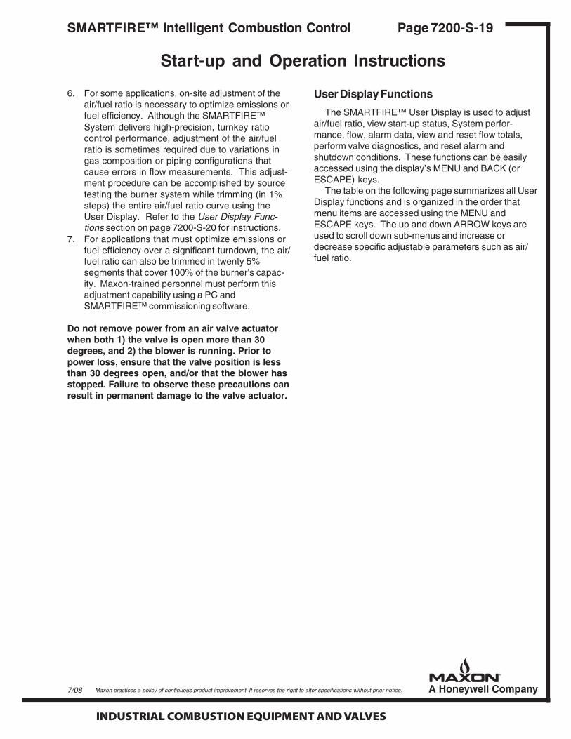
6. For some applications, on-site adjustment of theair/fuel ratio is necessary to optimize emissions orfuel efficiency. Although the SMARTFIRE™System delivers high-precision, turnkey ratiocontrol performance, adjustment of the air/fuelratio is sometimes required due to variations ingas composition or piping configurations thatcause errors in flow measurements. This adjust-ment procedure can be accomplished by sourcetesting the burner system while trimming (in 1%steps) the entire air/fuel ratio curve using theUser Display. Refer to the User Display Func-tions section on page 7200-S-20 for instructions.
7. For applications that must optimize emissions orfuel efficiency over a significant turndown, the air/fuel ratio can also be trimmed in twenty 5%segments that cover 100% of the burner’s capac-ity. Maxon-trained personnel must perform thisadjustment capability using a PC andSMARTFIRE™ commissioning software.
Do not remove power from an air valve actuatorwhen both 1) the valve is open more than 30degrees, and 2) the blower is running. Prior topower loss, ensure that the valve position is lessthan 30 degrees open, and/or that the blower hasstopped. Failure to observe these precautions canresult in permanent damage to the valve actuator.
Start-up and Operation Instructions
Page 7200-S-19SMARTFIRE™ Intelligent Combustion Control
7/08
User Display Functions
The SMARTFIRE™ User Display is used to adjustair/fuel ratio, view start-up status, System perfor-mance, flow, alarm data, view and reset flow totals,perform valve diagnostics, and reset alarm andshutdown conditions. These functions can be easilyaccessed using the display’s MENU and BACK (orESCAPE) keys.
The table on the following page summarizes all UserDisplay functions and is organized in the order thatmenu items are accessed using the MENU andESCAPE keys. The up and down ARROW keys areused to scroll down sub-menus and increase ordecrease specific adjustable parameters such as air/fuel ratio.

INDUSTRIAL COMBUSTION EQUIPMENT AND VALVES
Maxon practices a policy of continuous product improvement. It reserves the right to alter specifications without prior notice.
Page 7200-S-20 SMARTFIRE™ Intelligent Combustion Control
Start-up and Operation Instructions
snoitcnuFyalpsiDresUmetIuneMyalpsiDresU
)1etoNeeS(suneM-buS)2etoNeeS(
snoitpircseDuneM-buSdnauneM
SUTATSMETSYS seY .sutatsmraladnaatadmetsysweiV
reppuniegassem"pu-tratS"ybdetacidni(ssecorppu-tratsrenrubgniruD,snoitcapu-trats™ERIFTRAMSweiv,)yalpsiDresUforenrocdnahthgir
.smraladna,deecorpotdedeenstupni
taehweiv,)egassem"NOlortnoC"ybdetacidni(ssecorppu-tratsretfA.sutatsmraladnatuptuo/dnamed
evlavleuf/riadna,srorrewolf,swolfleufdnaria,oitar,etargnirifweiV.sunem-busgnisusnoitisop
SMRALADEHCTALTESER enoN niamersmralaesehT.snoitidnocmrala"dehctal"teserotyek]retnE[sserPtupni™ERIFTRAMSlitnurodetucexesinoitcnufyalpsidsihtlitnudetacidni
kcehcwolf,snwodtuhsmetsysedulcnismraladehctaL.delcycsirewop.smralatimildnamedwol/hgihdnasmrala
STIMILDNAMEDTESER enoN leufehtnehwteserastimilesehT.stimildnamedteserotyek]retnE[sserP)rellortnocerutarepmets'resUehtybdednamed(etargnirifehtrofwolfriaro
metsyS™ERIFTRAMSeht,dehcaersitimilanehW.deveihcaebtonnacoitarreporpstimreptahtlevelaotetargnirifmuminimromumixamstistsujda
.lortnoc
ATADNOITARUGIFNOC seY leufmuminim/mumixam:atadcificeps-noitsubmocdemmargorp-erpweiVsunem-buS.atadoitarleuf/riaderotsehtfoledomrenrubehtdnawolf
™ERIFTRAMSdellatsnihcaerofsrebmunnoisreverawtfosedulcni.tnenopmoc
OITARLEUF/RIATSUJDA enoN rehcirro)oitaresaercni(renaelevrucoitarleuf/riadellatsniehttsujdAsihT.syekWORRAnwodropuehtgnisserpybspets%1ni)oitaresaerced(
,nosirenrubehtfI.noroffosirenrubehtnehwdemrofrepebnacnoitcnufgnillortnocsimetsyS™ERIFTRAMSehtfidetucexeebylnolliwnoitcnufsiht
.tnioptesetargnirifdetseuqerehtta
LATOTWOLF seY renrubfosruohlatotgniweivedulcnisunem-buS.latotwolfleufweiVrofnoitcnufteseradna,latotwolf)elbacilppafi,negyxodna(leuf,noitarepo
.latothcae
LATOTNWODTUHS seY folavomer,.e.i(™ERIFTRAMSybdesuacsnwodtuhsrenrubforebmunweiVlatotsedulcniunem-buS.)tilsirenrubretfatuptuoYDAER™ERIFTRAMS
.latothcaerofnoitcnufteseradnasesuaclanretxerofsnwodtuhsmetsys
NOITARBILACEVLAV seY rotautcaevlavaedulcnisunem-buS.noitarbilacrotautcaevlavriamrofrePsnoitcnufesehtfoynanehW.tsetnoitisopesolc-nepodnakcehcnoitarbilac
sidnammocehtlitnudetibihnierasnoitcnufyekrehtolla,detucexeera.eunitnocotdesserpebtsumyek]retnE[ehtdnadetelpmoc
KCEHCWOLFELBASID/ELBANE
seY wolfedulcnisunem-buS.kcehcwolfenil-nosuounitnocehtelbasidroelbanEwolf,)egnarwolfdnaegnahcnoitisopevlavfoseergedni(stluserkcehc
nehwteseroslasikcehcwolfehT.teserkcehcwolfdna,sutatsmralakcehclliwkcehcwolfsagdnariaehT.nodnaffodelcycsirewop™ERIFTRAMSnasegnahcwolfnevigarofnoitisopevlavehtfinoitidnocmralanaecudorp
.dlohserhtdetcelesehtnahtretaergtnuoma
TROPPUSTCUDORP enoN .troppustcudorprof)3553-256-008-1(rebmuneerf-llotnoxaMweiV
.tsilunempuevomot)]epacsE[ro(]kcaB[sserP.unemnwodevomotyek]uneM[sserP:1etoN.sunem-busnwoddnapuevomotsyeknwodworra/puworrasserP:2etoN

INDUSTRIAL COMBUSTION EQUIPMENT AND VALVES
Maxon practices a policy of continuous product improvement. It reserves the right to alter specifications without prior notice.
Start-up and Operation Instructions
Page 7200-S-21SMARTFIRE™ Intelligent Combustion Control
Maxon Field Configuration
Using a PC connected to the SMARTFIRE™control network and SMARTFIRE™ commissioningsoftware, Maxon field personnel can perform thefollowing field configuration functions:
• For applications that require on-site optimiza-tion of emissions or fuel efficiency over awide turndown, the air/fuel ratio can beadjusted in twenty 5% segments of burnerfiring capacity. The adjustments can be madeleaner or richer in 1% steps.
• Modify maximum, minimum, and startingfiring rates due to fuel pressure limitations,undersized combustion blower, under-estimated pressure losses in piping.
• Modify starting fuel valve position for applica-tions with long piping runs between the shut-off valve and the burner and have a burnermanagement system with a very short mainflame-establishment period.
See the Product Support section on page 7200-S-22 for information on Maxon SMARTFIRE™ Techni-cal Support.
Local and Remote Monitoring
Local monitoring of the SMARTFIRE™ Systemcan be accomplished by connecting a User’s DCS(Distributed Control System) or data acquisitionsystem. This monitoring may be required to meetlocal environmental regulations that mandate arecord of air/fuel ratio performance data in place ofcostly periodic or continuous emissions monitoring.Local SMARTFIRE™ monitoring may also be usefulto help determine the cause of a burner shutdown.
The most straightforward method for local monitor-ing is to connect the User’s monitoring system to thetwo alarm contacts and the four isolated 4-20 mAoutputs that represent fuel and air flow and fuel and airvalve position.
Remote diagnostic support by Maxon field personnelcan also be performed with an optional SMARTFIRE™telephone gateway (Maxon P/N 1055838) and a localtelephone line. This remote monitoring option allowstrained personnel to log diagnostic control data andhelp the customer diagnose a problem without an on-site service call.
4/03
Maxon SMARTFIRE™ Telephone Gateway
INDUSTRIAL COMBUSTION EQUIPMENT AND VALVES
Maxon practices a policy of continuous product improvement. It reserves the right to alter specifications without prior notice.
Page 7200-S-22 SMARTFIRE™ Intelligent Combustion Control
Maintenance
The SMARTFIRE™ System continuously monitorsits components for proper operation and alarms whenfailures or maintenance issues arise. Maxon recom-mends a minimum monthly check for alarm condi-tions that are indicated by SMARTFIRE™ alarmcontacts and by alarm messages on the User Inter-face Display.
When alarms occur, the user should follow theTroubleshooting section of these instructions (Page7200-S-23) to determine if any maintenance action isrequired. For example, if a Flow Test or Flow LimitAlarm occurs, a flow limitation or sensing problemmay exist that requires cleaning of the combustionfan filter, removing debris in the flow conditioningscreens, or cleaning contaminates on the flow sensorprobe.
Maxon also recommends the calibration of theSMARTFIRE™ Air and Fuel Flow Controllers beverified at least every 5 years. This verification canbe accomplished in the field using the sensor valida-tion procedure described in the Start-up and Opera-tion section of these instructions (Page 7200-S-16 to21). For a more precise evaluation of sensor calibra-tion, the sensor probe assemblies can be removedfrom their flow bodies and shipped to Maxon Corpo-ration in Muncie, Indiana, for testing.
All maintenance work performed on the Fuel orAir Flow Controllers must be performed with theSystem turned off. Cleaning of the flow sensorprobes can be done with any solvent material suit-able for stainless steel. However, care should betaken not to bend the two small sensing probes. Re-validation of any flow sensor that has been cleanedor removed from its flow body is required before re-commissioning the combustion system.
If the SMARTFIRE™ System is applied in combus-tion systems with minimal combustion air filtering orwith fuel gas contaminants, the SMARTFIRE™ alarmcontacts should be monitored by the plant or processDCS system to alert personnel of improper operationand possible maintenance issues.
Product Support
Maxon Corporation provides 24-hour telephonesupport for all SMARTFIRE™ customers. If you havea question that relates to the installation, operation,or maintenance of the SMARTFIRE™ System,please call 800-652-3553 (within the United States orCanada) and your call will be answered immediatelyor returned as soon as possible.
Maintenance and Product Support

INDUSTRIAL COMBUSTION EQUIPMENT AND VALVES
Maxon practices a policy of continuous product improvement. It reserves the right to alter specifications without prior notice.
Troubleshooting
Page 7200-S-23SMARTFIRE™ Intelligent Combustion Control
resU/melborPmralAyalpsiD
esuaCelbissoP/noitpircseD noituloS/esnopseR
NAELOITARF/A""MRALA
yliratnemomebyampoollortnocwolF-,tnioptesstignitoohsrevo
tonsisrellortnoCwolFehtfoeno-ro,yltcerrocwolfgnirusaem
yamerusserp)rebmahcro(ylppusa-degnahcylneddusevah
wolfetadilav-er,etargniriftnatsnocatastsisrepmralafItuokcehC"ehtniserudecorpehtotgnidroccasgnidaer
noitarepOdnapu-tratSehtfonoitceS"putratSretfa.)81-S-0027egap(snoitcurtsnI
HCIROITARF/A""MRALA
)1etoN(
yliratnemomebyampoollortnocwolF-,tnioptesstignitoohsrevo
tonsisrellortnoCwolFehtfoeno-ro,yltcerrocwolfgnirusaem
yamerusserp)rebmahcro(ylppusa-degnahcylneddusevah
wolfetadilav-er,etargniriftnatsnocatastsisrepmralafItuokcehC"ehtniserudecorpehtotgnidroccasgnidaer
noitarepOdnapu-tratSehtfonoitceS"putratSretfa.)81-S-0027egap(snoitcurtsnI
,renrubehtnwodstuhsmetsyS™ERIFTRAMSehtfI.tupniteserlanretxeroyalpsiDresUehthtiwmralateser
)LEUFRO(RIA""MRALACDATCA
roscinortcelelortnocrotautcadeliaFnoitisopderiuqereveihcatonnacrotautca
htiwgnirefretnilairetamteksagroegnalf,sirbedrofkcehCllitsmraladnadnuofsiegakcolbonfI.tnemevomevlav
,metsysERIFTRAMSehtotrewopgnilcycretfastsixe.rotautcaecalper
)LEUFRO(RIA""MRALAV42TCA
egatlovylppusCDrotautcaegnar-fo-tuO ,ylppusdeliafa,ylppusCDV42dedaolylivaehrofkcehC.gnolootsinurelbacrotautcanarehtehwro
)LEUFRO(RIA""MRALALACTCA
detarbilactonsirotautcatnemecalpeRevlavanodellatsnigniebretfa
.yalpsiDresUehthtiwrotautcaehtetarbilac-eR
)LEUFRO(RIA""MRALAMMOCTCA
ahtiwetacinummoctonnacniarBrenruBrotautcAevlaV
ronoitcennocelbaclortnoctnettimretninarofkcehC.rotautcaecalper
)LEUFRO(RIA"4-1SOPTCA
"MRALA
deriuqerehteveihcatonnacrotautcanAtnioptesnoitisop
evlavtibihnidluoctahtevlavehtnisirbedsierehtfikcehCotscitsongaidevlavyalpsiDresUehtesudnatnemevomotyrtTONOD.esolcdnaneporotautcAevlaVehtevom
.deilpparewophtiwyllaunamevlavehtevom
ehtgnisudeweivebnacevlavehtfonoitisopehT.gnilpuocevlav-rotautcaehtnosgnikram
)LEUFRO(RIA"TESERTCA
"MRALA
ro/dnanoitucexeerawtfosreporpmIeruliafscinortcelelortnoc
esionlacirtceleegralaraensirotautcaehtfikcehC.elbissopfiecruosesionevomdnaecruos
.rotautcaecalper,sruccoernoitidnocmralafI
)LEUFRO(RIA""MRALAPMETTCA
erutarepmettneibmanoitacificeps-fo-tuOeruliafscinortcelelortnocrotautcanaro
evomerdnaerusolcnes'rotautcafoerutarepmetkcehC.tohootfinoitalucricetomorproecruostaeh
ecalper,gnitarmumixamraentonsierutarepmetfI.rotautca
)LEUFRO(RIA""MRALACDAWOLF
scinortcelelortnocwolfdeliaF llitsmralafidna,metsyS™ERIFTRAMSotrewopelcyC.rellortnoCwolFecalper,srucco
)LEUFRO(RIA"MMOCWOLF
"MRALA )1etoN(
ahtiwetacinummoctonnacniarBrenruBrellortnoCwolF
ronoitcennocelbaclortnoctnettimretninarofkcehC.rellortnoCwolFecalper
)LEUFRO(RIA""MRALAEBORP
tcerrocnignirusaemsirellortnocwolFswolf
wolFecalperdnarewop™ERIFTRAMSelcyceR.stsisrepmralafirellortnoC
:1etoN hcihwnoitidnocnwodtuhsaotdaellliw,evobaelbatgnitoohselbuorTnidetacidnisa,snoitidnocmralacificepS.tcatnoc1#mralAehtsesolcdnatcatnocevissimrepydaeRERIFTRAMSehtsnepo
4/03

INDUSTRIAL COMBUSTION EQUIPMENT AND VALVES
Maxon practices a policy of continuous product improvement. It reserves the right to alter specifications without prior notice.
Page 7200-S-24 SMARTFIRE™ Intelligent Combustion Control
Troubleshooting (Continued)
resU/melborPmralAyalpsiD esuaCelbissoP/noitpircseD noituloS/esnopseR
)LEUFRO(RIA"EGNARWOLF
"MRALA
)1etoN(
siegnartnemerusaems'rellortnoCwolFoitarleuf/riapool-desolcgniruddedeecxe
nostnanimatnoctew/erutsiomrolortnocstnemelegnisneswolfeht
:leuFrofsimralaehtfIgnirudwolfleufdetcetedrellortnoCwolF-tuhssagniamehterofebputratsrenrub
deneposevlavffo
,stnanimatnoc/erutsiomrofeborprosneswolfehttcepsnInoitanimatnoc/erutsiometanimiledna,yrassecenfinaelc
ehtrepsasgnidaerwolfetadilav-eR.elbissopfiecruosehtfonoitceS"putratSretfatuokcehC"ehtniserudecorp
.)81-S-0027egap(snoitcurtsnInoitarepOdnapu-tratS
ehtfogninepoerutamerprofkcehc,leufrofsimralafIniaM™ERIFTRAMSehterofebevlavffo-tuhssagniamffo-tuhssagehtkcehcdnadezigrenesitupniNOevlaV
.egakaelrofsevlav
,stsisrepmralaroliafsgnidaerwolffonoitadilav-erfIrellortnoCwolFecalper
)LEUFRO(RIA"TESERWOLF
"MRALA
wolfro/dnanoitucexeerawtfosreporpmIeruliafscinortcelelortnoc
esionlacirtceleegralaraensirellortnoCwolFfikcehCmralafI.elbissopfiecruosesionevomdnaecruos
.rellortnoCwolFecalper,sruccoernoitidnoc
)LEUFRO(RIA"PMETWOLF
"MRALA
erutarepmettneibmanoitacificeps-fo-tuOeruliafscinortcelelortnocwolfro
dnaerusolcnes'rellortnoCwolFfoerutarepmetkcehC.tohootfinoitalucricetomorproecruostaehevomer
wolFecalper,gnitarmumixamraentonsierutarepmetfI.rellortnoC
)LEUFRO(RIA"TSETWOLF
"MRALA
)2etoN( )2etoN( )2etoN( )2etoN( )2etoN(
wolfnevigarofegnahcnoitisopevlaVsihT.dlohserhtdetcelesehtsdeecxe
leufnisegnahcybdesuacebnacmraladekcolb,serusserpylppusriaro
rellortnoCwolF,retlifrianoitsubmockcabrebmahcnisegnahcegral,seruliafwolfnonoitanimatnoc/erutsiom,erusserp
stnemelegnisnes
.yrassecenfinaelcdnaretlifnafnoitsubmocehttcepsnI,stnanimatnoc/erutsiomrofeborprosneswolftcepsnI
noitanimatnoc/erutsiometanimiledna,yrassecenfinaelcehtrepsasgnidaerwolfetadilav-eR.elbissopfiecruos
ehtfonoitceS"putratSretfatuokcehC"ehtniserudecorpdna)81-S-0027egap(snoitcurtsnInoitarepOdnapu-tratS
.yalpsiDresUehthtiwmralaehtteser
wolFecalper,liafsgnidaerwolffonoitadilav-erfI.sruccoermralafirellortnoC
IH)LEUFRO(RIA""MRALATIMIL
,erusserpsagwol,rianoitsubmocfokcaLeruliafrellortnoCwolFaro
sagesaercni,egakcolbrofretlifrianoitsubmockcehCdnamralateseR.ecruosylppusriaesaercniro,erusserp
elcycroyalpsiDresUehthtiwstimildnamed.rewop™ERIFTRAMS
otgnidroccasgnidaerwolfetadilav-er,sruccoermralafIfonoitceS"putratSretfatuokcehC"ehtniserudecorpeht.)81-S-0027egap(snoitcurtsnInoitarepOdnapu-tratSeht
.rellortnoCwolFecalper,sliafnoitadilavfI
OL)LEUFRO(RIA""MRALATIMIL
saghgih,rewolbnoitsubmocdezisrevOeruliafrellortnoCwolFaro,erusserp
resUehthtiwmralateseR.erusserpriarosagesaerceD.rewop™ERIFTRAMSelcycroyalpsiD
otgnidroccasgnidaerwolfetadilav-er,sruccoermralafIfonoitceS"putratSretfatuokcehC"ehtnierudecorpeht
.)81-S-0027egap(snoitcurtsnInoitarepOdnapu-tratSeht
.rellortnoCwolFecalper,sliafnoitadilavfI
:1etoN hcihwnoitidnocnwodtuhsaotdaellliw,evobaelbatgnitoohselbuorTnidetacidnisa,snoitidnocmralacificepS.tcatnoc1#mralAehtsesolcdnatcatnocevissimrepydaeRERIFTRAMSehtsnepo
:2etoN ehtsselnu(metsysehtnwodtuhsTONlliwtubtcatnoc1#mralAehtesolclliwmralatsetwolfleufrorianAytefasnoitsubmocasadetcennocyalerlanretxelanoitiddanahtiwnwodtuhsmetsysaesuacottcatnocsihtsesuremotsuc
.)kcolretnigninnur

INDUSTRIAL COMBUSTION EQUIPMENT AND VALVES
Maxon practices a policy of continuous product improvement. It reserves the right to alter specifications without prior notice.
Troubleshooting (Continued)
Page 7200-S-25SMARTFIRE™ Intelligent Combustion Control
resU/melborPmralAyalpsiD
D esuaCelbissoP/noitpircse noituloS/esnopseR
PMETTNEIBMA""MRALA
tneibmaniarBrenruBnoitacificeps-fo-tuOscinortcelelortnocaroerutarepmet
eruliaf
evomerdnaniarBrenruBotesolcerutarepmetkcehCedivorP.tohootfinoitalucricetomorproecruostaeh
.dlocootfiecruostaehlanretxe
,gnitarmuminimromumixamraentonsierutarepmetfI.niarBrenruBecalper
CDANIARB""MRALA
latigid-ot-golanacinortceleniarBrenruBeruliaferawdrah)CDA(noisrevnoc
renruBecalper,stsisrepmralafidnametsysrewop-eR.niarB
MMOCREKCEHC""MRALA
htiwetacinummoctonnacniarBrenruBehtnihtiwerawdrahrekcehCwolFeht
niarBrenruB
eciveddleifehtfoB-ataDroA-ataDnotrohsarofkcehC.niarBrenruBehtecalperroelbaclortnoc
LORTNOC""DELBASID
htoberastupniBtceleSdnaAtceleStilsirenrubehtretfadezigrene
noitcnufsihtgnisusselnustupnihtobotrewopevomeRfoecalpnierutximria/enaporpaothctiwsagnirud
.saglarutan
WOLFRIAHGIH""MRALA
desolcsievlavriaehtfi,putratsgniruDehtthgilothgihootsiwolfriaehtdna
detacidnisimralawolfriahgiha,renrub
fI.)noitidnocegrupta(gnidaerwolfriaetadilav-eRgnirifmuminimdnaffothgilehtesaercni,dilavsignidaer
,sliafnoitadilavwolfriafI.erusserpriaecuderroetar.rellortnoCwolFriAecalper
WOLFLEUFHGIH""MRALA
wolFsaGarokaelevlavffo-tuhssaGeruliafrellortnoC
.gninoitcnufylreporperasevlavffo-tuhsleuffikcehC
elcycroyalpsiDresUehthtiwmralateseR.rewop™ERIFTRAMS
ecalper,sevlavffo-tuhsgnikcehcretfasruccoermralafI.rellortnoCwolFsaG
WOLFRIAWOL""MRALA
riAdeliafarorianoitsubmocfokcaLrellortnoCwolF
.nosirewolbrianoitsubmocfikcehC
.wolfriatcirtserdluoctahttsixesegakcolbynafikcehC
.renrubtaserusserpriakcehC
erusserpriadna,tsixesegakcolbon,derewopsirewolbfI.rellortnoCwolFriAecalper,elbanosaersispatrenrubta
RORREYROMEM""MRALA)1etoN(
detpurrocsiyromemniarBrenruB .niarBrenruBecalpeR
TNERRUCYLPPUS""MRALA
siylppusCDV42™ERIFTRAMSdedaolrevo
ataenoeciveddleifhcaetcennocsid,fforenrubehthtiW.tnerruchcumootgniwardtinuehtenimretedotemit
ro(GODHCTAW"TESER)METSYS
"MRALA)1etoN(
ro/dnanoitucexeerawtfosreporpmIeruliafscinortceleniarBrenruB
renruBecalper,stsisrepmralafidnametsysrewop-eR.niarB
:1etoN hcihwnoitidnocnwodtuhsaotdaellliw,evobaelbatgnitoohselbuorTnidetacidnisa,snoitidnocmralacificepS.tcatnoc1#mralAehtsesolcdnatcatnocevissimrepydaeRERIFTRAMSehtsnepo
:2etoN ehtsselnu(metsysehtnwodtuhsTONlliwtubtcatnoc1#mralAehtesolclliwmralatsetwolfleufrorianAytefasnoitsubmocasadetcennocyalerlanretxelanoitiddanahtiwnwodtuhsmetsysaesuacottcatnocsihtsesuremotsuc
.)kcolretnigninnur
1/11

INDUSTRIAL COMBUSTION EQUIPMENT AND VALVES
Maxon practices a policy of continuous product improvement. It reserves the right to alter specifications without prior notice.
Page 7200-S-26 SMARTFIRE™ Intelligent Combustion Control
SMARTFIRE™ Actuator Field Replacement Instructions
Actuator Removal
1. Verify that the SMARTFIRE™/Burner System iscompletely shut down and that the gas shut-offvalve is closed. DO NOT try to move the valvemanually with power on.
2. Remove the actuator access cover using a 4mmAllen wrench, and verify that there is no power tothe unit. The 3 lights (power, status, and diagnos-tic LEDs) should not be lit if power is off.
3. Record the wire color code sequence and thendisconnect the four lead wires from the terminalblock. Disconnect any conduit fittings.
4. Loosen the clamp collar screws with a 3/16” Allenwrench.
5. Remove the four M6x1x18mm socket head capscrews connecting the actuator to the valveadapter with a 5mm Allen wrench.
6. Remove the actuator by holding the actuatorhousing and pulling the actuator along the shaftaxis, away from the valve.
7. IMPORTANT: Move the valve to a fully closedposition using the hole below the clamp collar.
Actuator Reinstallation
1. Inspect the actuator coupling. Identify the type ofkey required based on the photos below.
3. Align the shaft key with the slot in the coupling andinsert the shaft into the coupling. Turn the actua-tor housing as needed so the alignment pin on theactuator is aligned with the valve adapter hole(closest to the open face of the valve adapter).
Note: Older units may have an alignmentbushing in place of a dowel pin.
If you have an older unit, remove the dowel pinfrom the replacement actuator with a pair of pliersand proceed with installation. To confirm properorientation of the actuator to the adapter, verifythat the pinhole is over the adapter opening priorto bolting in place.
4. The parts are a clearance fit but should sliptogether with little force. Apply pressure until theactuator is flat against the adapter. (DO NOT applyexcessive force — if the valve adapter andactuator do not mate together, recheck that theclamp is loose and the key is pressed to thebottom of the key slot.) Verify that the actuator isseated flush to the valve adapter. Install the fourM6x1x18 mm socket head cap screws and torqueto 18 in-lbs. with a 5mm Allen wrench.
5. Verify that the clamp collar is seated flush againstthe coupling shoulder. Tighten the socket head capscrews with a 3/16” Allen wrench and torque to 170in-lbs.
6. Remove the access cover using a 4mm Allenwrench and make the necessary water-tightelectrical conduit connection. Connect the fourwires to the terminal strip per the original colorcode sequence. Connect the shield wire to theterminal strip, keeping it as short as possible.
7. Apply power to the SMARTFIRE™ System and,using the User Interface Display, verify that theactuator has power and is communicating withthe Burner Brain.
8. Reinstall the access cover and torque the fourfasteners to 18 in-lbs. using a 4mm Allen wrench.
9. Run the actuator calibration function from the UserInterface Display main menu.
See next page for schematic of typical Valve/Actuator assemblies.
Blind keyway Open keyway
Blind keyway requires 1/8” x 1/8” square key.Open keyway requires 1/8” x 3/16” rectangular key.
2. IMPORTANT: Verify that the clamp collar isloose and the valve is in a fully closedposition. The collar should have the screw headon the left when looking at the clamp with thecollar at the top.
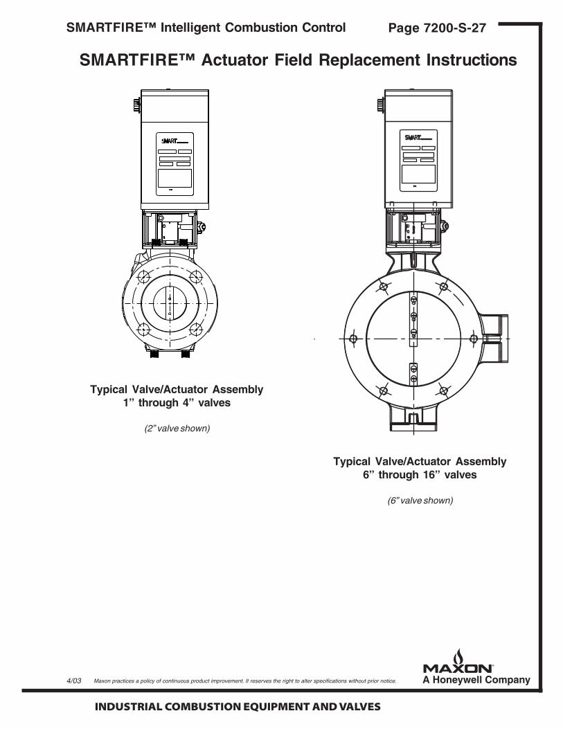
INDUSTRIAL COMBUSTION EQUIPMENT AND VALVES
Maxon practices a policy of continuous product improvement. It reserves the right to alter specifications without prior notice.
Page 7200-S-27SMARTFIRE™ Intelligent Combustion Control
Typical Valve/Actuator Assembly1” through 4” valves
(2” valve shown)
4/03
Typical Valve/Actuator Assembly6” through 16” valves
(6” valve shown)
SMARTFIRE™ Actuator Field Replacement Instructions

INDUSTRIAL COMBUSTION EQUIPMENT AND VALVES
Maxon practices a policy of continuous product improvement. It reserves the right to alter specifications without prior notice.
Page 7200-S-28 SMARTFIRE™ Intelligent Combustion Control
Notes