INTELLI-HOOD TROUBLESHOOTING GUIDE - …® Troubleshooting Guide I. About this Document The purpose...
12
INTELLI-HOOD ® TROUBLESHOOTING GUIDE Melink Corporation (513) 965-7300 www.melinkcorp.com ®
Transcript of INTELLI-HOOD TROUBLESHOOTING GUIDE - …® Troubleshooting Guide I. About this Document The purpose...

INTELLI-HOOD® TROUBLESHOOTING GUIDE
Melink Corporation (513) 965-7300 www.melinkcorp.com
®
1
Last Updated 7/22/2015
Table of Contents
Page
I. About this Document 2
II. Related Documents 2
III. Glossary of Abbreviations 3
IV. Diagnostics/Troubleshooting 4
a. Touchpad Display 4
b. System Controller 6
c. Hood Controller 7
d. Optic/Temp Sensor 7
e. VFD’s 8
f. EF’s 9
g. MUA Interlock 9
h. BAS/BACnet 10
i. AIO 10
j. ALC 11
k. APD 11

2
Intelli-Hood® Troubleshooting Guide
I. About this Document
The purpose of this document is to provide basic troubleshooting techniques for the Intelli-Hood Kitchen Control System. The intended audience of this document is the end user of the system: the building owner, kitchen manager, kitchen staff, or maintenance technician.
II. Related Documents
Operations and Maintenance Manual
Provides information regarding basic operation & maintenance.
Installation Manual
Provides detailed installation instructions of the components including mechanical installation of parts, power wiring, and control wiring.
VFD Manuals
Refer to documents provided by the VFD manufacturer for information regarding any aspect of the Variable Frequency Drives including power wiring, control wiring, programming, and faults. Information can be found on their respective web pages.
System is continually expanding capabilities. Presently, capable of utilizing Modbus control for ABB, Allen-Bradley, Trane, Danfoss, Siemens, Schneider, Samsung, & Yaskawa.

3
III. Glossary of Abbreviations
The following terms and abbreviations are used throughout literature pertaining to the Intelli-Hood System.
IH: Intelli-Hood
VFD: Variable Frequency Drive
TP: Touchpad
APU: Air Purge Unit
SC: System Controller
HC: Hood Controller
AT: Auxiliary Touchpad
AIO: Auxiliary Analog Out Device
ALC: Auxiliary Light Controller
APD: Auxiliary Power Device
EF: Exhaust Fan
MUA: Make Up Air
4
IV. Diagnostics/Troubleshooting
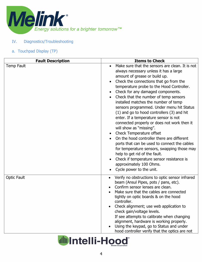
a. Touchpad Display (TP)
Fault Description Items to Check
Temp Fault Make sure that the sensors are clean. It is not
always necessary unless it has a large
amount of grease or build up.
Check the connections that go from the
temperature probe to the Hood Controller.
Check for any damaged components.
Check that the number of temp sensors
installed matches the number of temp
sensors programmed. Under menu hit Status
(1) and go to hood controllers (3) and hit
enter. If a temperature sensor is not
connected properly or does not work then it
will show as “missing”.
Check Temperature offset
On the hood controller there are different
ports that can be used to connect the cables
for temperature sensors, swapping those may
help to get rid of the fault.
Check if temperature sensor resistance is
approximately 100 Ohms.
Cycle power to the unit.
Optic Fault Verify no obstructions to optic sensor infrared beam (Ansul Pipes, pots / pans, etc).
Confirm sensor lenses are clean. Make sure that the cables are connected
tightly on optic boards & on the hood controller.
Check alignment; use web application to
check gain/voltage levels.
If see attempts to calibrate when changing alignment, hardware is working properly.
Using the keypad, go to Status and under hood controller verify that the optics are not

5
missing.
Cycle power to the unit.
Variable Frequency Drive (VFD) Comm. Fault VFD type (ABB, Allen Bradley, Danfoss, etc) may not be identified correctly in Exhaust Fan or Aux Airflow programming.
Check EF &MUA Aux Airflow status and confirm VFD type is correct.
Check display on VFD(s) for a fault (i.e. F5 or F13). Go to respective VFD and confirm if any fault codes exist and troubleshoot in accordance with VFD User’s Manual.
Touchpad Frozen System may have lost configuration or configuration file was corrupted, tech support downloads the configuration files and emails it to the technician working on site. The tech will drag it to the root directory of a USB and save it as a ConfigurationFiles.zip file, power off the unit, place USB in port, cycle power on to the unit.
Verify that the base board LED’s are lighting up. Power the system controller off, replace the cell battery on the base board then power back on.
Confirm proper addressing of Network Devices (Hood Controllers and Touchpads).
Unable to enter System Configuration Enter menu screen on Touchpad, and with System Configuration selected, press and hold up/down arrows until text changes from red to blue (Approx 15 seconds)
Touchpad not displaying correct devices (OR) Multiple Touchpads on same SC are frozen
Check hardcoded address on Touchpad (TP), press and hold the up/down arrows on the TP for 30 seconds. Change address to correct number. Power cycle System Controller to hardcode new address. Replacement TP maybe defaulted to address of 1.
Check programming of devices in service app.
Light Button Works but TP is blank TP ribbon cable loose between boards (OR) boards not seated
Fans Button not working Check Exhaust Hood menu. Confirm on/off
6
control is set to correct Touchpad address
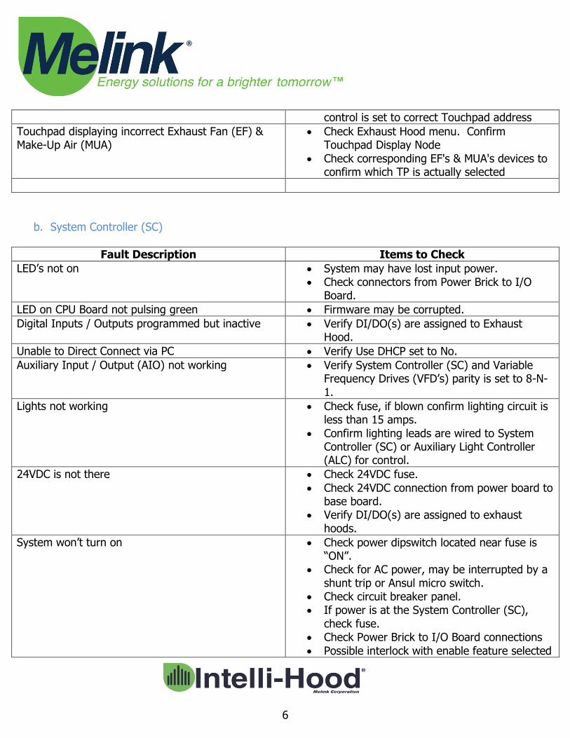
Touchpad displaying incorrect Exhaust Fan (EF) & Make-Up Air (MUA)
Check Exhaust Hood menu. Confirm Touchpad Display Node
Check corresponding EF's & MUA's devices to confirm which TP is actually selected
b. System Controller (SC)
Fault Description Items to Check
LED’s not on System may have lost input power. Check connectors from Power Brick to I/O
Board.
LED on CPU Board not pulsing green Firmware may be corrupted.
Digital Inputs / Outputs programmed but inactive Verify DI/DO(s) are assigned to Exhaust Hood.
Unable to Direct Connect via PC Verify Use DHCP set to No.
Auxiliary Input / Output (AIO) not working Verify System Controller (SC) and Variable Frequency Drives (VFD’s) parity is set to 8-N-1.
Lights not working Check fuse, if blown confirm lighting circuit is less than 15 amps.
Confirm lighting leads are wired to System Controller (SC) or Auxiliary Light Controller (ALC) for control.
24VDC is not there Check 24VDC fuse.
Check 24VDC connection from power board to base board.
Verify DI/DO(s) are assigned to exhaust hoods.
System won’t turn on Check power dipswitch located near fuse is “ON”.
Check for AC power, may be interrupted by a shunt trip or Ansul micro switch.
Check circuit breaker panel. If power is at the System Controller (SC),
check fuse. Check Power Brick to I/O Board connections
Possible interlock with enable feature selected
7
to Building Automation System (BAS) or Water Wash Panel.
Digital Input / Outputs are not controlling proper hoods
Confirm “Hood Groups” programmed correctly
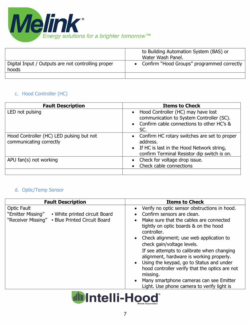
c. Hood Controller (HC)
Fault Description Items to Check
LED not pulsing Hood Controller (HC) may have lost communication to System Controller (SC).
Confirm cable connections to other HC’s & SC.
Hood Controller (HC) LED pulsing but not communicating correctly
Confirm HC rotary switches are set to proper address.
If HC is last in the Hood Network string, confirm Terminal Resistor dip switch is on.
APU fan(s) not working Check for voltage drop issue. Check cable connections
d. Optic/Temp Sensor
Fault Description Items to Check
Optic Fault “Emitter Missing” ▪ White printed circuit Board “Receiver Missing” ▪ Blue Printed Circuit Board
Verify no optic sensor obstructions in hood. Confirm sensors are clean. Make sure that the cables are connected
tightly on optic boards & on the hood controller.
Check alignment; use web application to
check gain/voltage levels.
If see attempts to calibrate when changing alignment, hardware is working properly.
Using the keypad, go to Status and under hood controller verify that the optics are not missing.
Many smartphone cameras can see Emitter Light. Use phone camera to verify light is
8
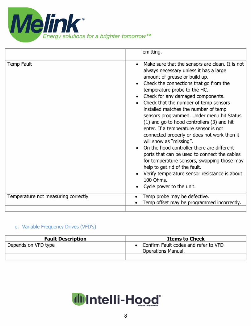
emitting.
Temp Fault Make sure that the sensors are clean. It is not
always necessary unless it has a large
amount of grease or build up.
Check the connections that go from the
temperature probe to the HC.
Check for any damaged components.
Check that the number of temp sensors
installed matches the number of temp
sensors programmed. Under menu hit Status
(1) and go to hood controllers (3) and hit
enter. If a temperature sensor is not
connected properly or does not work then it
will show as “missing”.
On the hood controller there are different
ports that can be used to connect the cables
for temperature sensors, swapping those may
help to get rid of the fault.
Verify temperature sensor resistance is about
100 Ohms.
Cycle power to the unit.
Temperature not measuring correctly Temp probe may be defective.
Temp offset may be programmed incorrectly.
e. Variable Frequency Drives (VFD’s)
Fault Description Items to Check
Depends on VFD type Confirm Fault codes and refer to VFD Operations Manual.
9
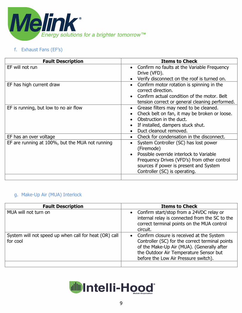
f. Exhaust Fans (EF’s)
Fault Description Items to Check
EF will not run Confirm no faults at the Variable Frequency Drive (VFD).
Verify disconnect on the roof is turned on.
EF has high current draw Confirm motor rotation is spinning in the correct direction.
Confirm actual condition of the motor. Belt tension correct or general cleaning performed.
EF is running, but low to no air flow Grease filters may need to be cleaned. Check belt on fan, it may be broken or loose. Obstruction in the duct. If installed, dampers stuck shut.
Duct cleanout removed.
EF has an over voltage Check for condensation in the disconnect.
EF are running at 100%, but the MUA not running System Controller (SC) has lost power (Firemode)
Possible override interlock to Variable Frequency Drives (VFD’s) from other control sources if power is present and System Controller (SC) is operating.
g. Make-Up Air (MUA) Interlock
Fault Description Items to Check
MUA will not turn on Confirm start/stop from a 24VDC relay or internal relay is connected from the SC to the correct terminal points on the MUA control circuit.
System will not speed up when call for heat (OR) call for cool
Confirm closure is received at the System Controller (SC) for the correct terminal points of the Make-Up Air (MUA). (Generally after the Outdoor Air Temperature Sensor but before the Low Air Pressure switch).

10
h. Building Automation System (BAS) & BACnet
Fault Description Items to Check
BAS cannot discover System Controller (SC) Check Ethernet cable and port connection.
Confirm IP address in the About Screen.
Check IP settings are configured per site’s IT requirements in the System Menu. Static IP (If not using DHCP), Netmask, Gateway, Domain Name System (DNS) Server 1, DNS Server 2
BAS cannot discover Exhaust Fan (EF) & Make-Up Air (MUA) data
Destination Network (DNET) number might need to be changed from 1 to a unique number to avoid data collision
i. Auxiliary Input / Output (AIO)
Fault Description Items to Check
AIO won’t work Check connections, 24VDC and digital comms from System Controller (SC) to AIO.
Confirm device exists in configuration, configuration settings and associated AUX air flows programmed and their associated devices providing speed reference.
Confirm parity in SC and Variable Frequency Drives (VFD’s) is set to 8-N-1.
Confirm dip switch on module set to “Normal”

11
j. Auxiliary Light Controller (ALC)
Fault Description Items to Check
ALC won’t work Check Ethernet cable and port connection. Confirm light controller address selected on
touchpad for lights operation.
Confirm device exists in configuration. Confirm lighting circuit is connected to ALC
from control.
k. Auxiliary Power Device (APD)
Fault Description Items to Check
APD is not boosting signal Check circuit breaker. Check connections. Check for power.