
Intelli-M Hardware Installation and Reference manual 1: Intelli-M® Hardware Overview 8 Intelli-M...
46
Hardware Installation And Reference www.infinias.com
Transcript of Intelli-M Hardware Installation and Reference manual 1: Intelli-M® Hardware Overview 8 Intelli-M...

Hardware Installation And Reference
www.infinias.com

2 Intelli-M Hardware Installation And Reference Guide
Preface
This manual is a hardware installation and reference for the Intelli-M® access control security system. An overview of a typical configuration for a hardware installation is provided, as well as a description of the major Intelli-M hardware components that can be used. Technical specifications for each Intelli-M hardware component are also provided.
Trademarks
All brand or product names mentioned herein are used for identification purposes only and may be trademarks or registered trademarks of their respective companies.
Intelli-M Hardware Installation And Reference Manual
All Rights Reserved.
Reproduction, adaptation, or translation of this document without prior written permission is prohibited, except as allowed under copyright laws.
Printed in the United States.
Note: The information in this document is subject to change without notice or obligation.
infinias, the infinias logo, and Intelli-M are registered trademarks of infinias, LLC
© Copyright 2009 infinias, LLC
Intelli-M Hardware Installation And Reference Manual 3
Table of Contents
OFFICIAL NOTICES . . . . . . . . . . . . . . . . . . . . . . . . . . . . . . . . . . . . . . . . . . . . . . . . . . . . . . . . . . . . 5FCC Declaration Of Conformity (S-EIDC-U, S-PCON-U) . . . . . . . . . . . . . . . . . . . . . . . . . 5UL Compliance (S-EIDC-U, S-PCON-U) . . . . . . . . . . . . . . . . . . . . . . . . . . . . . . . . . . . . . . 5
CHAPTER 1: INTELLI-M® HARDWARE OVERVIEW . . . . . . . . . . . . . . . . . . . . . . . . . . . . . . . . . . 7Contents . . . . . . . . . . . . . . . . . . . . . . . . . . . . . . . . . . . . . . . . . . . . . . . . . . . . . . . . . . . . . . . . . . . 7
Intelli-M Hardware Overview . . . . . . . . . . . . . . . . . . . . . . . . . . . . . . . . . . . . . . . . . . . . . . . . 8Using This Manual . . . . . . . . . . . . . . . . . . . . . . . . . . . . . . . . . . . . . . . . . . . . . . . . . . . . . . . . . 9
CHAPTER 2: S-EIDC-U (ETHERNET INTEGRATED DOOR CONTROLLER) . . . . . . . . . . . . . . . 11Contents . . . . . . . . . . . . . . . . . . . . . . . . . . . . . . . . . . . . . . . . . . . . . . . . . . . . . . . . . . . . . . . . . . 11
S-EIDC-U Overview . . . . . . . . . . . . . . . . . . . . . . . . . . . . . . . . . . . . . . . . . . . . . . . . . . . . . . 12Technical Features . . . . . . . . . . . . . . . . . . . . . . . . . . . . . . . . . . . . . . . . . . . . . . . . . . . . . . . . . . . . . . . . . . . . . 12
Wiring S-EIDC-U Door Components . . . . . . . . . . . . . . . . . . . . . . . . . . . . . . . . . . . . . . . . . 13Powering Up An S-EIDC-U . . . . . . . . . . . . . . . . . . . . . . . . . . . . . . . . . . . . . . . . . . . . . . . . . 15Determining The Network IP Address Type . . . . . . . . . . . . . . . . . . . . . . . . . . . . . . . . . . . . 16Setting A Static IP Address Within The S-EIDC-U . . . . . . . . . . . . . . . . . . . . . . . . . . . . . . . 17Setting A DHCP IP Address Within The S-EIDC-U . . . . . . . . . . . . . . . . . . . . . . . . . . . . . . 18
Setting An S-EIDC-U For DHCP Addressing . . . . . . . . . . . . . . . . . . . . . . . . . . . . . . . . . . . . . . . . . . . . . . . . 18Resetting An S-EIDC-U . . . . . . . . . . . . . . . . . . . . . . . . . . . . . . . . . . . . . . . . . . . . . . . . . . . . 19Quick Mount Assembly . . . . . . . . . . . . . . . . . . . . . . . . . . . . . . . . . . . . . . . . . . . . . . . . . . . . 19
CHAPTER 3: S-PCON-U (POWER CONNECTOR) . . . . . . . . . . . . . . . . . . . . . . . . . . . . . . . . . . . 21Contents . . . . . . . . . . . . . . . . . . . . . . . . . . . . . . . . . . . . . . . . . . . . . . . . . . . . . . . . . . . . . . . . . . 21
S-PCON-U Overview . . . . . . . . . . . . . . . . . . . . . . . . . . . . . . . . . . . . . . . . . . . . . . . . . . . . . . 22Technical Features . . . . . . . . . . . . . . . . . . . . . . . . . . . . . . . . . . . . . . . . . . . . . . . . . . . . . . . . . . . . . . . . . . . . . 22
Wiring And Powering Up S-PCON-U . . . . . . . . . . . . . . . . . . . . . . . . . . . . . . . . . . . . . . . . . 23
CHAPTER 4: WIRING CONNECTIONS AND CONFIGURATIONS . . . . . . . . . . . . . . . . . . . . . . . . . 25Contents . . . . . . . . . . . . . . . . . . . . . . . . . . . . . . . . . . . . . . . . . . . . . . . . . . . . . . . . . . . . . . . . . . 25
Sample S-EIDC-U Global Configuration . . . . . . . . . . . . . . . . . . . . . . . . . . . . . . . . . . . . . . . 26S-EIDC-U Wiring Terminals . . . . . . . . . . . . . . . . . . . . . . . . . . . . . . . . . . . . . . . . . . . . . . . . 27Single Door Door Configuration With S-EIDC-U . . . . . . . . . . . . . . . . . . . . . . . . . . . . . . . . 28
APPENDIX A: EFAMILY UPDATE UTILITY
(BACKUP, UPGRADE, AND RESTORE EFAMILY DEVICE SOFTWARE) . . . . . . . . . . . . . . . . . . . 29Contents . . . . . . . . . . . . . . . . . . . . . . . . . . . . . . . . . . . . . . . . . . . . . . . . . . . . . . . . . . . . . . . . . . 29
Installing The eFamily Update Utility . . . . . . . . . . . . . . . . . . . . . . . . . . . . . . . . . . . . . . . . . 30Supervisor Plus Users . . . . . . . . . . . . . . . . . . . . . . . . . . . . . . . . . . . . . . . . . . . . . . . . . . . . . . . . . . . . . . . . . . 30Web Interface Users . . . . . . . . . . . . . . . . . . . . . . . . . . . . . . . . . . . . . . . . . . . . . . . . . . . . . . . . . . . . . . . . . . . . 30
Before Updating Your eFamily Device . . . . . . . . . . . . . . . . . . . . . . . . . . . . . . . . . . . . . . . . 32eFamily Update Procedure . . . . . . . . . . . . . . . . . . . . . . . . . . . . . . . . . . . . . . . . . . . . . . . . . . 32Errors That Occur During Update . . . . . . . . . . . . . . . . . . . . . . . . . . . . . . . . . . . . . . . . . . . . 37
Table Of Contents
4 Intelli-M Hardware Installation And Reference Manual
APPENDIX B: DEMO KIT WIRING . . . . . . . . . . . . . . . . . . . . . . . . . . . . . . . . . . . . . . . . . . . . . . . 39
APPENDIX C: INTELLI-M® HARDWARE TECHNICAL SPECIFICATIONS . . . . . . . . . . . . . . . . . 41S-EIDC-U Technical Specifications (Ethernet Integrated Door Controller) . . . . . . . . . . . . . . 41
Dimensions . . . . . . . . . . . . . . . . . . . . . . . . . . . . . . . . . . . . . . . . . . . . . . . . . . . . . . . . . . . . . . 41Ethernet IDC . . . . . . . . . . . . . . . . . . . . . . . . . . . . . . . . . . . . . . . . . . . . . . . . . . . . . . . . . . . . . . . . . . . . . . . . . 41Weight . . . . . . . . . . . . . . . . . . . . . . . . . . . . . . . . . . . . . . . . . . . . . . . . . . . . . . . . . . . . . . . . . . . . . . . . . . . . . . 41
Quick Mount Assembly Kit Enclosure . . . . . . . . . . . . . . . . . . . . . . . . . . . . . . . . . . . . . . . . . 41Recessed Mounting Box . . . . . . . . . . . . . . . . . . . . . . . . . . . . . . . . . . . . . . . . . . . . . . . . . . . . . . . . . . . . . . . . . 41Plaster Ring . . . . . . . . . . . . . . . . . . . . . . . . . . . . . . . . . . . . . . . . . . . . . . . . . . . . . . . . . . . . . . . . . . . . . . . . . . 41Cover Plate . . . . . . . . . . . . . . . . . . . . . . . . . . . . . . . . . . . . . . . . . . . . . . . . . . . . . . . . . . . . . . . . . . . . . . . . . . 41
Environmental . . . . . . . . . . . . . . . . . . . . . . . . . . . . . . . . . . . . . . . . . . . . . . . . . . . . . . . . . . . . 41Operating Temperature . . . . . . . . . . . . . . . . . . . . . . . . . . . . . . . . . . . . . . . . . . . . . . . . . . . . . . . . . . . . . . . . . 41Storage Temperature . . . . . . . . . . . . . . . . . . . . . . . . . . . . . . . . . . . . . . . . . . . . . . . . . . . . . . . . . . . . . . . . . . . 41Humidity . . . . . . . . . . . . . . . . . . . . . . . . . . . . . . . . . . . . . . . . . . . . . . . . . . . . . . . . . . . . . . . . . . . . . . . . . . . . . 41
Power . . . . . . . . . . . . . . . . . . . . . . . . . . . . . . . . . . . . . . . . . . . . . . . . . . . . . . . . . . . . . . . . . . 42Communication . . . . . . . . . . . . . . . . . . . . . . . . . . . . . . . . . . . . . . . . . . . . . . . . . . . . . . . . . . . 42Reader Ports . . . . . . . . . . . . . . . . . . . . . . . . . . . . . . . . . . . . . . . . . . . . . . . . . . . . . . . . . . . . . 42Inputs . . . . . . . . . . . . . . . . . . . . . . . . . . . . . . . . . . . . . . . . . . . . . . . . . . . . . . . . . . . . . . . . . . 42Outputs . . . . . . . . . . . . . . . . . . . . . . . . . . . . . . . . . . . . . . . . . . . . . . . . . . . . . . . . . . . . . . . . . 42Certifications . . . . . . . . . . . . . . . . . . . . . . . . . . . . . . . . . . . . . . . . . . . . . . . . . . . . . . . . . . . . . 42
S-PCON-U Technical Specifications (Power Controller) . . . . . . . . . . . . . . . . . . . . . . . . . . . . 43Dimensions . . . . . . . . . . . . . . . . . . . . . . . . . . . . . . . . . . . . . . . . . . . . . . . . . . . . . . . . . . . . . . 43
Power Connector Module (S-PCON-U) . . . . . . . . . . . . . . . . . . . . . . . . . . . . . . . . . . . . . . . . . . . . . . . . . . . . 43Weight . . . . . . . . . . . . . . . . . . . . . . . . . . . . . . . . . . . . . . . . . . . . . . . . . . . . . . . . . . . . . . . . . . . . . . . . . . . . . . 43Composition . . . . . . . . . . . . . . . . . . . . . . . . . . . . . . . . . . . . . . . . . . . . . . . . . . . . . . . . . . . . . . . . . . . . . . . . . . 43
Environmental . . . . . . . . . . . . . . . . . . . . . . . . . . . . . . . . . . . . . . . . . . . . . . . . . . . . . . . . . . . . 43Operating Temperature . . . . . . . . . . . . . . . . . . . . . . . . . . . . . . . . . . . . . . . . . . . . . . . . . . . . . . . . . . . . . . . . . 43Storage Temperature . . . . . . . . . . . . . . . . . . . . . . . . . . . . . . . . . . . . . . . . . . . . . . . . . . . . . . . . . . . . . . . . . . . 43Humidity . . . . . . . . . . . . . . . . . . . . . . . . . . . . . . . . . . . . . . . . . . . . . . . . . . . . . . . . . . . . . . . . . . . . . . . . . . . . . 43
Operational . . . . . . . . . . . . . . . . . . . . . . . . . . . . . . . . . . . . . . . . . . . . . . . . . . . . . . . . . . . . . . 43Input Connectors . . . . . . . . . . . . . . . . . . . . . . . . . . . . . . . . . . . . . . . . . . . . . . . . . . . . . . . . . . . . . . . . . . . . . . 43Output Connector . . . . . . . . . . . . . . . . . . . . . . . . . . . . . . . . . . . . . . . . . . . . . . . . . . . . . . . . . . . . . . . . . . . . . . 43Output Indicator . . . . . . . . . . . . . . . . . . . . . . . . . . . . . . . . . . . . . . . . . . . . . . . . . . . . . . . . . . . . . . . . . . . . . . . 43Power In . . . . . . . . . . . . . . . . . . . . . . . . . . . . . . . . . . . . . . . . . . . . . . . . . . . . . . . . . . . . . . . . . . . . . . . . . . . . . 44Power Out . . . . . . . . . . . . . . . . . . . . . . . . . . . . . . . . . . . . . . . . . . . . . . . . . . . . . . . . . . . . . . . . . . . . . . . . . . . 44
Miscellaneous Computer Hardware Specifications . . . . . . . . . . . . . . . . . . . . . . . . . . . . . . . . . 45Performance Communications Server Requirements . . . . . . . . . . . . . . . . . . . . . . . . . . . . . . 45
Minimum Server Requirements . . . . . . . . . . . . . . . . . . . . . . . . . . . . . . . . . . . . . . . . . . . . . . . . . . . . . . . . . . . 45Performance Badging / Workstation Requirements . . . . . . . . . . . . . . . . . . . . . . . . . . . . . . . 45
Minimum Badging / Workstation Requirements . . . . . . . . . . . . . . . . . . . . . . . . . . . . . . . . . . . . . . . . . . . . . . 46Digital Camera . . . . . . . . . . . . . . . . . . . . . . . . . . . . . . . . . . . . . . . . . . . . . . . . . . . . . . . . . . . 46USB Camera (WebCam) . . . . . . . . . . . . . . . . . . . . . . . . . . . . . . . . . . . . . . . . . . . . . . . . . . . 46Signature Capture . . . . . . . . . . . . . . . . . . . . . . . . . . . . . . . . . . . . . . . . . . . . . . . . . . . . . . . . . 46Modem . . . . . . . . . . . . . . . . . . . . . . . . . . . . . . . . . . . . . . . . . . . . . . . . . . . . . . . . . . . . . . . . . 46Network Requirements . . . . . . . . . . . . . . . . . . . . . . . . . . . . . . . . . . . . . . . . . . . . . . . . . . . . . 46
Intelli-M Hardware Installation And Reference Guide 5
Official Notices
FCC Declaration Of Conformity (S-EIDC-U, S-PCON-U) This equipment has been tested and found to comply with the limits for a Class B digital device, pursuant to part 15 of the FCC Rules. These limits are designed to provide reasonable protection against harmful interference in a residential installation. This equipment generates, uses and can radiate radio frequency energy and, if not installed and used in accordance with the instructions, may cause harmful interference to radio communications. However, there is no guarantee that interference will not occur in a particular installation. If this equipment does cause harmful interference to radio or television reception, which can be determined by turning the equipment off and on, the user is encouraged to try to correct the interference by one or more of the following measures:
• Reorient or relocate the receiving antenna.• Increase the separation between the equipment and receiver.• Connect the equipment into an outlet on a circuit different from that to which the receiver is
connected.• Consult the dealer or an experienced radio/TV technician for help
UL Compliance (S-EIDC-U, S-PCON-U)
requirements of UL294, Standards for Access Control System Units, and found to comply with the aforementioned standards set by Underwriters Laboratories (UL).
infinias models S-EIDC-U and S-PCON-U have been evaluated in accordance with the

Official Notices
6 Intelli-M Hardware Installation And Reference Guide
Intelli-M Hardware Installation And Reference Guide 7
Chapter 1: Intelli-M® Hardware Overview
Contents
This Chapter provides an overview of the Intelli-M system for electronic access control (EAC). A section describing the layout of this manual is also provided.
The following topics can be found within this Chapter:
• Intelli-M Hardware Overview
• Using This Manual
Chapter 1: Intelli-M® Hardware Overview
8 Intelli-M Hardware Installation And Reference Guide
Intelli-M Hardware Overview
This manual provides reference, installation, and technical specifications for the hardware products that are used with the Intelli-M system. Technical specifications for each product are also provided. The following Intelli-M hardware products are discussed in this manual, and are currently available:
• S-EIDC-U (ethernet Integrated Door Controller) in Chapter 2
• S-PCON-U (Power Connector) in Chapter 3
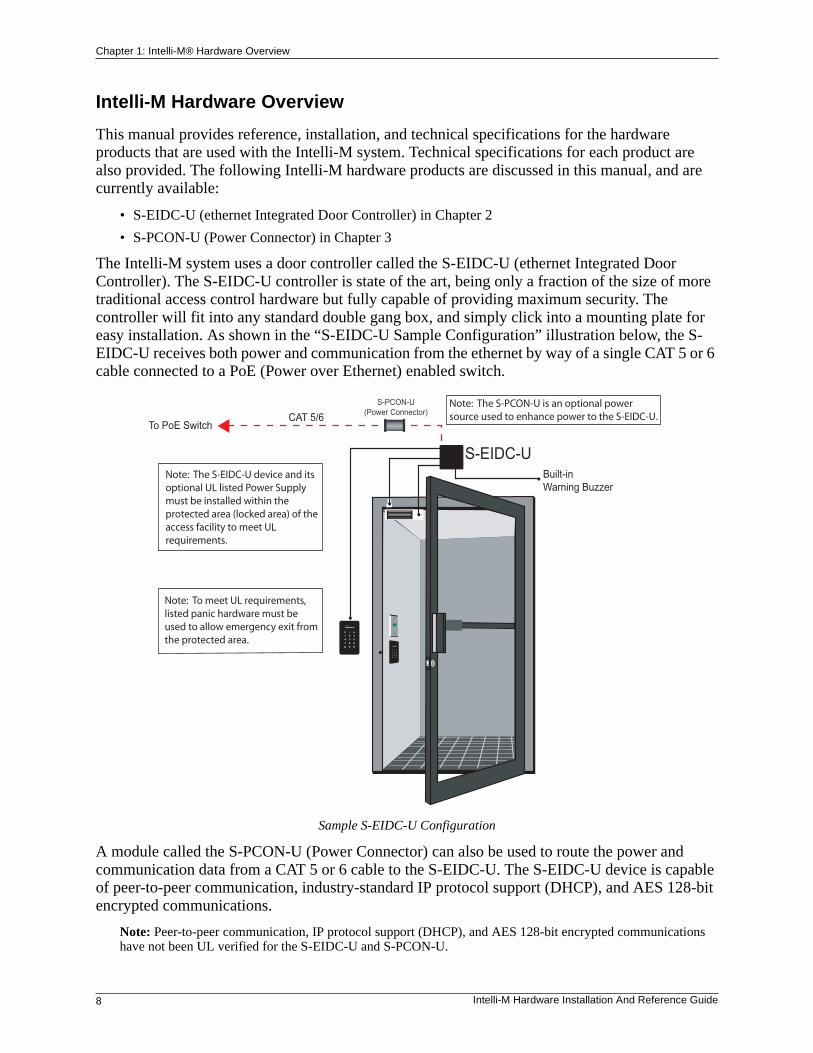
The Intelli-M system uses a door controller called the S-EIDC-U (ethernet Integrated Door Controller). The S-EIDC-U controller is state of the art, being only a fraction of the size of more traditional access control hardware but fully capable of providing maximum security. The controller will fit into any standard double gang box, and simply click into a mounting plate for easy installation. As shown in the “S-EIDC-U Sample Configuration” illustration below, the S-EIDC-U receives both power and communication from the ethernet by way of a single CAT 5 or 6 cable connected to a PoE (Power over Ethernet) enabled switch.
Sample S-EIDC-U Configuration
A module called the S-PCON-U (Power Connector) can also be used to route the power and communication data from a CAT 5 or 6 cable to the S-EIDC-U. The S-EIDC-U device is capable of peer-to-peer communication, industry-standard IP protocol support (DHCP), and AES 128-bit encrypted communications.
Note: Peer-to-peer communication, IP protocol support (DHCP), and AES 128-bit encrypted communications have not been UL verified for the S-EIDC-U and S-PCON-U.
Built-inWarning Buzzer
CAT 5/6
S-EIDC-U
To PoE Switch
Note: The S-EIDC-U device and its optional UL listed Power Supply must be installed within the protected area (locked area) of the access facility to meet UL requirements.
S-PCON-U(Power Connector)
Note: The S-PCON-U is an optional power source used to enhance power to the S-EIDC-U.
Note: To meet UL requirements, listed panic hardware must be used to allow emergency exit from the protected area.
Chapter 1: Intelli-M® Hardware Overview
Intelli-M Hardware Installation And Reference Guide 9
Using This Manual
This manual provides reference and installation guidance for the hardware components that are used in the Intelli-M system. Technical specifications are provided. Here is a quick overview of this manual’s Chapters and Appendices:
• Chapter 1: Intelli-M Hardware Overview -- Provides an overview of the Intelli-M system and a brief description of all Chapters and Appendices used in this manual.
• Chapter 2: S-EIDC-U (Ethernet Integrated Door Controller) -- Provides a description and lists some features of the S-EIDC-U. Also discussed are wiring connections, wiring door components, powering up, and resetting the S-EIDC-U.
• Chapter 3: S-PCON-U (Power Controller) -- Provides a description and lists some features of the S-PCON-U module. Also discussed are wiring and powering up the S-PCON-U.
• Chapter 4: Wiring Connections And Configurations -- Wiring connections and configurations for the Intelli-M hardware components are shown in this Chapter.
• Appendix A: Intelli-M eFamily Update Utility -- This Appendix describes how to use the eFamily Update Utility. This utility provides the ability to update the firmware of an eFamily device (such as an S-EIDC-U), backup a device configuration (including card holders, schedules, and services) and event history log, and/or restore a backup configuration.
• Appendix B: Demo Kit Wiring -- Provides the default configuration parameters if wiring the S-EIDC-U for a demo kit.
• Appendix C: Intelli-M Hardware Technical Specifications -- Gives the technical specifications for the for the various Intelli-M hardware components discussed in this manual.

Chapter 1: Intelli-M® Hardware Overview
10 Intelli-M Hardware Installation And Reference Guide
Intelli-M Hardware Installation And Reference Guide 11
Chapter 2: S-EIDC-U(ethernet Integrated Door Controller)
Contents
This Chapter provides a basic description of the Intelli-M® S-EIDC-U. Technical features are listed, and various wiring and power up configurations are shown.
The following topics can be found within this Chapter:
• S-EIDC-U Overview
• Wiring S-EIDC-U Door Components
• Powering Up An S-EIDC-U
• Determining The Network IP Address Type
Note: Network communication formats and configurations have not been UL verified for the S-EIDC-U and S-PCON-U.
• Setting A Static IP Address Within The S-EIDC-U
• Setting A DHCP IP Address Within The S-EIDC-U
• Resetting An S-EIDC-U
• Quick Mount Assembly
Chapter 2: S-EIDC-U (ethernet Integrated Door Controller)
12 Intelli-M Hardware Installation And Reference Guide
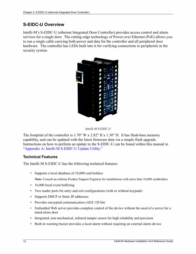
S-EIDC-U OverviewIntelli-M’s S-EIDC-U (ethernet Integrated Door Controller) provides access control and alarm services for a single door. The cutting-edge technology of Power over Ethernet (PoE) allows you to run a single cable carrying both power and data for the controller and all peripheral door hardware. The controller has LEDs built into it for verifying connections to peripherals in the security system.
Intelli-M S-EIDC-U
The footprint of the controller is 1.70" W x 2.82" H x 1.30" D. It has flash-base memory capability, and can be updated with the latest firmware data via a simple flash upgrade. Instructions on how to perform an update to the S-EIDC-U can be found within this manual in “Appendix A: Intelli-M S-EIDC-U Update Utility.”
Technical Features
The Intelli-M S-EIDC-U has the following technical features:
• 16,000 local event buffering• Two reader ports for entry and exit configurations (with or without keypads)• Supports DHCP or Static IP addresses• Provides encrypted communication (AES 128 bit)• Embedded Web server provides complete control of the device without the need of a server for a
stand-alone door• Integrated, non-mechanical, infrared tamper sensor for high reliability and precision• Built-in warning buzzer provides a local alarm without requiring an external alarm device
• Supports a local database of 10,000 card holders
Note: Consult an infinias Product Support Engineer for installations with more than 10,000 cardholders.
Chapter 2: S-EIDC-U (ethernet Integrated Door Controller)
Intelli-M Hardware Installation And Reference Guide 13
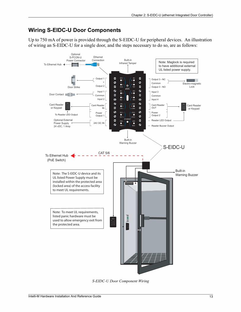
Wiring S-EIDC-U Door ComponentsUp to 750 mA of power is provided through the S-EIDC-U for peripheral devices. An illustration of wiring an S-EIDC-U for a single door, and the steps necessary to do so, are as follows:
S-EIDC-U Door Component Wiring
Built-inWarning Buzzer
CAT 5/6S-EIDC-U
To Ethernet Hub
Electro-magneticLockDoor Strike
Door Contact
Card Readeror Keypad
Card Readeror Keypad
Built-inWarning Buzzer
Built-inInfrared TamperTo Ethernet Hub
Optional S-PCON-U
Power ConnectorEthernet
Connection
Output 1
Output 2
Input 1
Input 2Common
Card Reader IN
PowerOutput 1
24V DC INOptional External Power Supply24 vDC, 1 Amp
Output 3 - NC
Output 3 - NOCommon
Input 3
Input 4Common
Card ReaderOUT
PowerOutput 2
Reader LED Output
Reader Buzzer Output
To Reader LED Output
Note: The S-EIDC-U device and its UL listed Power Supply must be installed within the protected area (locked area) of the access facility to meet UL requirements.
Note: Maglock is required to have additional external UL listed power supply.
(PoE Switch)
Note: To meet UL requirements, listed panic hardware must be used to allow emergency exit from the protected area.
Chapter 2: S-EIDC-U (ethernet Integrated Door Controller)
14 Intelli-M Hardware Installation And Reference Guide
The steps necessary to wire an S-EIDC-U for a single door are as follows:
Step 1: Connect magnetic lock or door strike. Refer to the illustration above. The following information may be pertinent when dealing with locks or door strikes:
• A magnetic lock or door strike can be powered by the eIDC (12 VDC @ 450 mA or less). This is a shared load.
• The two Open Collector outputs “OC1” and “OC2” (Output 1 and Output 2) provide a maxi-mum of 12 VDC @ 450 mA combined.
• “OC1” and “OC2” each have their own “-” terminal but share a “+” terminal.• “OC1” and “OC2” are software configurable “E” (energized) or “DE” (de-energized).
• Magnetic locks can be powered by the Open Collector output if it draws less than 450 mA. If it draws more than 450 mA, then it must be wired to the form C relay (5A @ 30 VDC) labeled “NC” and “NO” and powered externally.
• Relay (Output 3) has separate terminals for “C” (Common), “NO” (Normally Open), and “NC” (Normally Closed) but the software designation must match for proper status reporting.
Important: To meet UL requirements, listed panic hardware must be used to allow emergency exit from the protected area.
Step 2: Wire the status, shunt, and exit inputs. Keep in mind the following points:
• Input devices can be wired to S-EIDC-U Inputs (IN) 1-4.• “NO” or “NC” is software configurable with Inputs 1-4.• “EOLR” (End Of Line Resistance) supervision is software selectable, and is supported with 1k
ohm resistors.
Step 3: Wire the readers. Keep in mind the following points:
• Reader IN (CRI) and Reader OUT (CRO) are internally configured each having their own Data 0 (CR-), Data 1 (CR+), DC+, and DC-.
• “DC1-” has a maximum load of 250 mA; “DC2-” has a maximum load of 250 mA.• The sum of all 4 open collectors (OC1 + OC2 + DC1 + DC2) must not exceed 750 mA.• There is a single terminal for optional Reader LED control and optional Buzzer control.• Only Readers can be wired to the Reader’s Data 0 (CR-), and Data 1 (CR+) terminals.
Chapter 2: S-EIDC-U (ethernet Integrated Door Controller)
Intelli-M Hardware Installation And Reference Guide 15
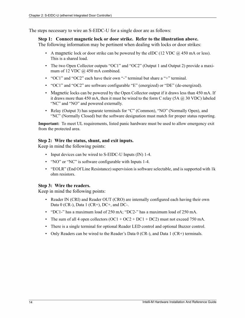
Powering Up An S-EIDC-U
The S-EIDC-U is designed to be powered from either a PoE enabled switch or from an external power source. Use one of the power configuration options shown in the Figure below to provide power to an S-EIDC-U.
S-EIDC-U Power Configuration Options
Option 1 -- Using PoE, run directly from Switch to S-EIDC-U.
Option 2 -- Using PoE, run directly from Switch to S-PCON-U, use S-PCON-U for power injection, and then run from S-PCON-U to S-EIDC-U.
Note: The External Power Supply connected to the S-PCON-U in Option 2 may not be required.
Option 3 -- Using non-PoE, run directly from Switch to S-EIDC-U and inject power at the installation site through the external power supply ports on the S-EIDC-U.
Option 4 -- Using non-PoE, run from Switch to S-PCON-U, use S-PCON-U for power injec-tion, and then run from S-PCON-U to S-EIDC-U.
When using POE, bear in mind that an S-EIDC-U will request the maximum power of 15.4 watts from the PoE switch port to which it is connected. A PoE enabled switch has a total power budget that is divided among all the PoE switch ports; therefore, the total power draw from all PoE equipment connected to the switch cannot exceed the switch power budget. Make sure that the
Four Power Options
S-PCON-U S-EIDC-U
PoECAT 5/6
non-PoE
CAT 5/6
non-PoE
CAT 5/6ExternalPower Supply24 VDC, 1 Amp
ExternalPower Supply24 VDC, 1 Amp
S-PCON-U
S-EIDC-U
PoE
CAT 5/6
S-EIDC-U
S-EIDC-U 1
2
3
4
hctiwS
ExternalPower Supply24 VDC, 1 Amp
Chapter 2: S-EIDC-U (ethernet Integrated Door Controller)
16 Intelli-M Hardware Installation And Reference Guide
aggregate power draw of all PoE powered devices does not exceed the total power budget of the switch. Exceeding the power budget of a PoE enabled switch will cause an S-EIDC-U to randomly fail.
Important: If both a PoE enabled switch and DC power are connected to the S-PCON-U, priority is given to the DC power supply. In such instances, PoE power is still being allocated by the PoE switch and counts toward the aggregate total power budget of the switch.
Determining The Network IP Address Type
Note: Network communication formats and configurations have not been UL verified for the S-EIDC-U and S-PCON-U.
The S-EIDC-U controller will appear as a full IP client on the data network, and thus will require an IP address. The network connection for the S-EIDC-U will be for either static addressing or DHCP (Dynamic Host Configuration Protocol) addressing. Use of either a DHCP permanently leased IP address or a static IP address is required by the S-EIDC-U.
Whenever power is initially applied to the S-EIDC-U, the S-EIDC-U will signal the current IP address that it is receiving. (Signaling also will occur when the S-EIDC-U is rebooted, that is, disconnected and then connected.) To determine the IP address type, connect power to the S-EIDC-U and note the address reported by the device as follows:
1. Use the LEDs on the S-EIDC-U unit when you are ready to note the IP address. If you look at the S-EIDC-U closely, each of the top five LEDs on each side have a number (left side 1-5 and right side 6-0).
2. Disconnect the power from the S-EIDC-U and then reconnect the power. The S-EIDC-U unit will boot and then attempt to acquire an IP address. (This happens because the S-EIDC-U is shipped from the factory set for DHCP addressing).
3. If the following sequence occurs when power is connected to the S-EIDC-U, the network IP address type may or may not be DHCP:
• All LEDs will flash three times to begin the sequence. (The S-EIDC-U is fully operational dur-ing IP address flashing.)
• A numbered (LED) will flash representing each number in the IP address. Each number group is separated by all LEDs flashing once. For example: 145.198.1.1 interprets as #1 flash #4 flash #5 flash <all flash> #1 flash #9 flash #8 flash <all flash> #1 flash <all flash> #1 flash <all flash>.
• Once the sequence has repeated 3 times, the S-EIDC-U LEDs will return to normal operation mode.
Important: If DHCP addressing is to be used, the DHCP address must be a permanently leased address. Read the section “Setting A DHCP IP Address Within The S-EIDC-U” later in this Chapter. Then check with the Network Administrator at the location for the availability of permanently leased DHCP addresses.
4. If the following sequence occurs when power is connected to the S-EIDC-U, the network IP address type is static:
• All of the LEDs on the S-EIDC-U unit flash continuously for about 10 seconds (more than 3 times) after the S-EIDC-U receives power.
Chapter 2: S-EIDC-U (ethernet Integrated Door Controller)
Intelli-M Hardware Installation And Reference Guide 17
This means a DHCP IP address cannot be determined (i.e., there is no DHCP connection). When this occurs, the S-EIDC-U will revert to its built in default static address of 169.254.1.1
Note: The default static address can be changed when the S-EIDC-U is configured. Refer to the section “Setting A Static IP Address Within The S-EIDC-U” below.
Setting A Static IP Address Within The S-EIDC-UAn S-EIDC-U can be statically addressed using a permanent IP Address, Subnet Mask, and Gateway (i.e., default route). To do this, perform the following steps:
1. To determine the current IP address of the controller, use the LEDs on the S-EIDC-U unit and note the IP address. If you look at the S-EIDC-U closely, each of the top five LEDs on each side have a number (left side 1-5 and right side 6-0).
2. Disconnect the power from the S-EIDC-U and then reconnect the power. The IP address of the device will be displayed three times on power up. IP address interpretation from LEDs is as follows:
• All LEDs will flash three times to begin the sequence. (The S-EIDC-U is fully operational dur-ing IP address flashing.)
• A numbered (LED) will flash representing each number in the IP address. Each number group is separated by all LEDs flashing once. For example: 145.198.1.1 interprets as #1 flash #4 flash #5 flash <all flash> #1 flash #9 flash #8 flash <all flash> #1 flash <all flash> #1 flash <all flash>.
• Once the sequence has repeated 3 times, the S-EIDC-U LEDs will return to normal operation mode. Note that the entire sequence can be repeated at any time by power cycling the S-EIDC-U.
3. Obtain a valid static IP Address, Subnet Mask, and Gateway that is to be set into the S-EIDC-U from the Network Administrator of the facility where the S-EIDC-U is located.
4. Using a standard web browser, browse to the IP address obtained in Steps 1 and 2 above. Click the “Start” button to be presented with a login screen. The default user Name is admin and the default Password is admin (all lower case).
Note: If the Name and/or Password have been changed in the device and are unknown, the S-EIDC-U will need to be reset to its factory defaults to enable access. Refer to “Resetting an S-EIDC-U” later in this Chapter to perform a hardware reset.
5. Click the “System” button and then click “Controllers.”
6. Select the S-EIDC-U controller (i.e., click to highlight the line) and then click the “Modify” button.
7. Uncheck the “Use DHCP” box by clicking it. This enables the IP Address, Subnet Mask, and Gateway fields so that they can be changed.
8. Type the new IP Address, Subnet Mask, and Gateway information into the appropriate fields.
9. Click “Ok” and then “Done” to set the changes. The S-EIDC-U is now ready for further configuration and use.

Chapter 2: S-EIDC-U (ethernet Integrated Door Controller)
18 Intelli-M Hardware Installation And Reference Guide
Setting A DHCP IP Address Within The S-EIDC-U
When using DHCP addressing, an S-EIDC-U on power up sends a request for an address lease to any DHCP server on the network. If a DHCP server is present on the network, that server will respond with an IP address, Subnet Mask, and Gateway (i.e., an alternate route) for the S-EIDC-U. The S-EIDC-U will store this information.
There are two primary types of DHCP addressing, which are as follows:
• Dynamic DHCP addressing with an expiration time limit
• Permanently Leased DHCP addressing
The S-EIDC-U requires Permanently Leased DHCP addressing. The problem with Dynamic DHCP addressing is that after a time the address assigned to an S-EIDC-U may expire, and the network could assign the S-EIDC-U a different address. If Supervisor Plus software is used with the S-EIDC-U, then Supervisor Plus may still be configured with the expired address. When this happens, random failures can occur within the S-EIDC-U and Supervisor Plus software application. If DHCP addressing is to be used at a location, check with the location’s network administrator to ensure that only Permanently Leased DHCP addressing will be used with S-EIDC-U(s).
Note: The Supervisor Plus software has not been UL verified.
Important: Do not use Dynamic DHCP addressing with an expiration time limit. Always check with the network administrator to make sure that the network will be using Permanently Leased DHCP addressing if DHCP addressing is to be used with an S-EIDC-U.
Setting An S-EIDC-U For DHCP Addressing
The S-EIDC-U is shipped from the factory set for DHCP addressing. If you are not sure an S-EIDC-U is set for DHCP addressing, or need to set an S-EIDC-U for DHCP addressing, do the following:
1. Perform the steps described in the “Determining The Network IP Address Type” section above to get the S-EIDC-U’s current address.
2. Using a standard web browser, browse to the IP address obtained in Step 1.
3. Click the “Start” button to be presented with a login screen. The default user Name is admin and the default Password is admin (all lower case).
Note: If the Name and/or Password have been changed in the device and are unknown, the S-EIDC-U will need to be reset to its factory defaults to enable access. Refer to “Resetting an S-EIDC-U” later in this Chapter to perform a hardware reset.
4. Click the “System” button and then click “Controllers.”
5. Select the S-EIDC-U controller (i.e., click to highlight the line) and then click the “Modify” button.
6. Make sure that the “Use DHCP” box has a check mark in it. If unchecked, click the box to add a check mark to it. This enables DHCP addressing for the S-EIDC-U.
7. Click “Ok” and then “Done” to set the change.
Chapter 2: S-EIDC-U (ethernet Integrated Door Controller)
Intelli-M Hardware Installation And Reference Guide 19
Resetting An S-EIDC-U
To perform a hardware reset of an S-EIDC-U, perform the following steps:
Step 1: Disconnect power from the S-EIDC-U. Refer to the “Powering Up An S-EIDC-U” section above to see the possible power connections.
Step 2: Disconnect any wiring that may be connected at Input 2 and at BUZ. Then place a jumper at Input 2 and BUZ (that is, connect the Input 2 terminal to the BUZ terminal with a wire.)
Step 3: Reconnect power to the S-EIDC-U, and then after about 3 or 4 seconds remove the jumper (without removing power) that connects the Input 2 terminal to the BUZ terminal.
Step 4: Wait for the LEDs to start flashing the IP address sequence. (You may have to wait up to 5 minutes before the flashing occurs.) Once the LEDs start to flash, recycle power to the S-EIDC-U by disconnecting the power to the S-EIDC-U and then reconnecting the power.
Once Step 4 has been performed, the reset procedure is complete and the S-EIDC-U will have been restored to its factory default.
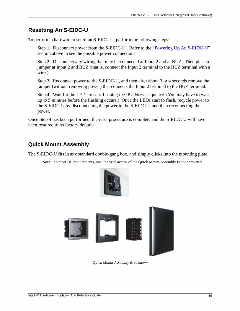
Quick Mount Assembly
The S-EIDC-U fits in any standard double-gang box, and simply clicks into the mounting plate.
Note: To meet UL requirements, unauthorized access of the Quick Mount Assembly is not permitted.
Quick Mount Assembly Breakdown

Chapter 2: S-EIDC-U (ethernet Integrated Door Controller)
20 Intelli-M Hardware Installation And Reference Guide

Intelli-M Hardware Installation And Reference Guide 21
Chapter 3: S-PCON-U(Power Connector)
Contents
This Chapter provides a basic description of the Intelli-M® S-PCON-U. Various wiring and power up configurations for the S-PCON-U are shown.
The following topics can be found within this Chapter:
• S-PCON-U Overview
• Wiring And Powering Up S-PCON-U

Chapter 3: S-PCON-U (Power Connector)
22 Intelli-M Hardware Installation And Reference Guide
S-PCON-U Overview
The Intelli-M Power Connector Module (S-PCON-U) is a dual input, single output power supply and communications module for the Intelli-M ethernet IDC (S-EIDC-U). It provides a method for supplying power and ethernet communication into the S-EIDC-U over a standard ethernet cable. Power is connected into the S-PCON-U via a PoE (Power over Ethernet) enabled switch connected to the input RJ45 ethernet connector, and/or by an external 24 VDC power supply connected to the DC input connector.
Note: PoE has not been UL verified.
Intelli-M S-PCON-U
Technical Features
The Intelli-M S-PCON-U has the following technical features:
• Supports one S-EIDC-U
• One ethernet “In” port with capability of accepting PoE power at 48 VDC (350 mA)
• One ethernet “Out” port with capability of passing through PoE power at 48 VDC (350 mA)
• One connector capable of accepting 24 VDC from an external power supply
• LED voltage indicator
This device complies with part 15 of the FCC rules.Operation is subject to the following two conditions: (1) Thisdevice may not cause harmful interference, and (2) Thisdevice must accept any interference received, includinginterference that may cause undesired operation.
22.9-24VDC@1A
@
@
Chapter 3: S-PCON-U (Power Connector)
Intelli-M Hardware Installation And Reference Guide 23
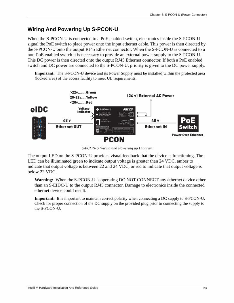
Wiring And Powering Up S-PCON-U
When the S-PCON-U is connected to a PoE enabled switch, electronics inside the S-PCON-U signal the PoE switch to place power onto the input ethernet cable. This power is then directed by the S-PCON-U onto the output RJ45 Ethernet connector. When the S-PCON-U is connected to a non-PoE enabled switch it is necessary to provide an external power supply to the S-PCON-U. This DC power is then directed onto the output RJ45 Ethernet connector. If both a PoE enabled switch and DC power are connected to the S-PCON-U, priority is given to the DC power supply.
Important: The S-PCON-U device and its Power Supply must be installed within the protected area (locked area) of the access facility to meet UL requirements.
S-PCON-U Wiring and Powering up Diagram
The output LED on the S-PCON-U provides visual feedback that the device is functioning. The LED can be illuminated green to indicate output voltage is greater than 24 VDC, amber to indicate that output voltage is between 22 and 24 VDC, or red to indicate that output voltage is below 22 VDC.
Warning: When the S-PCON-U is operating DO NOT CONNECT any ethernet device other than an S-EIDC-U to the output RJ45 connector. Damage to electronics inside the connected ethernet device could result.
Important: It is important to maintain correct polarity when connecting a DC supply to S-PCON-U. Check for proper connection of the DC supply on the provided plug prior to connecting the supply to the S-PCON-U.
This device complies with part 15 of the FCC rules.Operation is subject to the following two conditions: (1) Thisdevice may not cause harmful interference, and (2) Thisdevice must accept any interference received, includinginterference that may cause undesired operation.
22.9-24VDC@1A
@
@

Chapter 3: S-PCON-U (Power Connector)
24 Intelli-M Hardware Installation And Reference Guide
Intelli-M Hardware Installation And Reference Guide 25
Chapter 4: Wiring Connections And Configurations
Contents
This Chapter provides a description of the wiring connections for various Intell-M products, and various configurations diagrams featuring the products as well.
The following wiring connections and configuration diagrams can be found within this Chapter:
• Sample S-EIDC-U Global Configuration
• S-EIDC-U Wiring Terminals
• Single Door Configuration With S-EIDC-U
Chapter 4: Wiring Connections And Configurations
26 Intelli-M Hardware Installation And Reference Guide
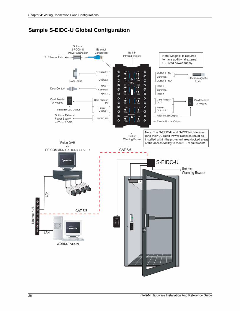
Sample S-EIDC-U Global Configuration
Built-inWarning Buzzer
CAT 5/6
S-EIDC-U
Electro-magneticLockDoor Strike
Door Contact
Card Readeror Keypad
Card Readeror Keypad
Built-inWarning Buzzer
Built-inInfrared TamperTo Ethernet Hub
Optional S-PCON-U
Power ConnectorEthernet
Connection
Output 1
Output 2
Input 1
Input 2Common
Card Reader IN
PowerOutput 1
24V DC INOptional External Power Supply24 vDC, 1 Amp
Output 3 - NC
Output 3 - NOCommon
Input 3
Input 4Common
Card ReaderOUT
PowerOutput 2
Reader LED Output
Reader Buzzer Output
To Reader LED Output
WORKSTATION
Pelco DVRor
PC COMMUNICATION SERVER
CAT 5/6
Note: The S-EIDC-U and S-PCON-U devices (and their UL listed Power Supplies) must be installed within the protected area (locked area) of the access facility to meet UL requirements.
Note: Maglock is required to have additional external UL listed power supply.
Chapter 4: Wiring Connections And Configurations
Intelli-M Hardware Installation And Reference Guide 27
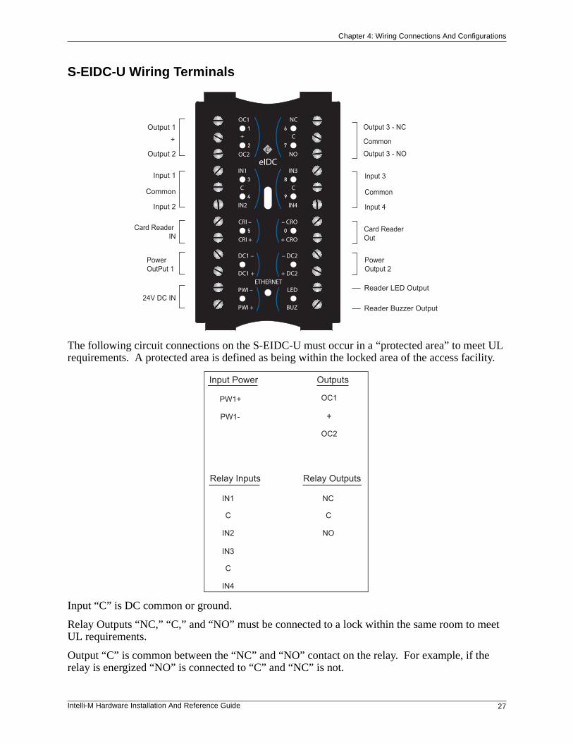
S-EIDC-U Wiring Terminals
The following circuit connections on the S-EIDC-U must occur in a “protected area” to meet UL requirements. A protected area is defined as being within the locked area of the access facility.
Input “C” is DC common or ground.
Relay Outputs “NC,” “C,” and “NO” must be connected to a lock within the same room to meet UL requirements.
Output “C” is common between the “NC” and “NO” contact on the relay. For example, if the relay is energized “NO” is connected to “C” and “NC” is not.
Output 1
+
Output 2
Input 1
Common
Input 2
Card Reader IN
Power OutPut 1
Output 3 - NC
Common
Output 3 - NO
Input 3
Common
Input 4
Card ReaderOut
PowerOutput 2
24V DC INReader Buzzer Output
Reader LED Output
Input Power Outputs
PW1+
PW1-
OC1
+
OC2
Relay Inputs Relay Outputs
IN1
C
IN2
IN3
C
IN4
NC
C
NO
Chapter 4: Wiring Connections And Configurations
28 Intelli-M Hardware Installation And Reference Guide
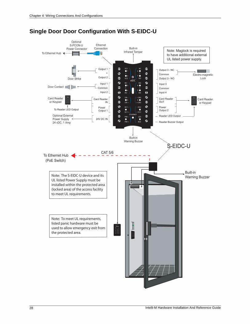
Single Door Door Configuration With S-EIDC-U
Built-inWarning Buzzer
CAT 5/6S-EIDC-U
To Ethernet Hub
Electro-magneticLockDoor Strike
Door Contact
Card Readeror Keypad
Card Readeror Keypad
Built-inWarning Buzzer
Built-inInfrared TamperTo Ethernet Hub
Optional S-PCON-U
Power ConnectorEthernet
Connection
Output 1
Output 2
Input 1
Input 2Common
Card Reader IN
PowerOutput 1
24V DC INOptional External Power Supply24 vDC, 1 Amp
Output 3 - NC
Output 3 - NOCommon
Input 3
Input 4Common
Card ReaderOUT
PowerOutput 2
Reader LED Output
Reader Buzzer Output
To Reader LED Output
Note: The S-EIDC-U device and its UL listed Power Supply must be installed within the protected area (locked area) of the access facility to meet UL requirements.
Note: Maglock is required to have additional external UL listed power supply.
(PoE Switch)
Note: To meet UL requirements, listed panic hardware must be used to allow emergency exit from the protected area.
Intelli-M Hardware Installation And Reference Guide 29
Appendix A: eFamily Update Utility(Backup, Upgrade, And Restore eFamily Device Software)
Contents
The eFamily Update Utility provides the ability to update the firmware, backup the device configuration (including card holders, schedules, and services) and event history log, and/or restore a backup configuration to an eFamily device.
The following topics can be found within this Appendix:
• Installing The eFamily Update Utility
• Before Updating Your eFamily Device
• eFamily Update Procedure
• Errors That Occur During Update
Appendix A: eFamily Update Utility (Backup, Upgrade, And Restore eFamily Device Software)
30 Intelli-M Hardware Installation And Reference Guide
Installing The eFamily Update Utility
Installation of the eFamily Update Utility is dependent on Intelli-M® Supervisor Plus or the Intelli-M® Web Interface.
Note: The Supervisor Plus software has not been UL verified.
Supervisor Plus Users
The eFamily Update Utility can be found on the Intelli-M Supervisor Plus installation CD. Once the CD is placed into the CD-ROM drive, right-click on the CD-ROM drive icon within “My Computer” and select “Open.” Navigate to the eFamily Update Utility folder, and then follow the installation procedure steps below.
Web Interface Users
Installation Procedure
The procedure for installing the eFamily Update Utility is as follows:
1. If the file was downloaded from the Web site, unzip the downloaded file.
Important: Make a note of where you unzip the file contents, as you will need the unzipped files during the update procedure.
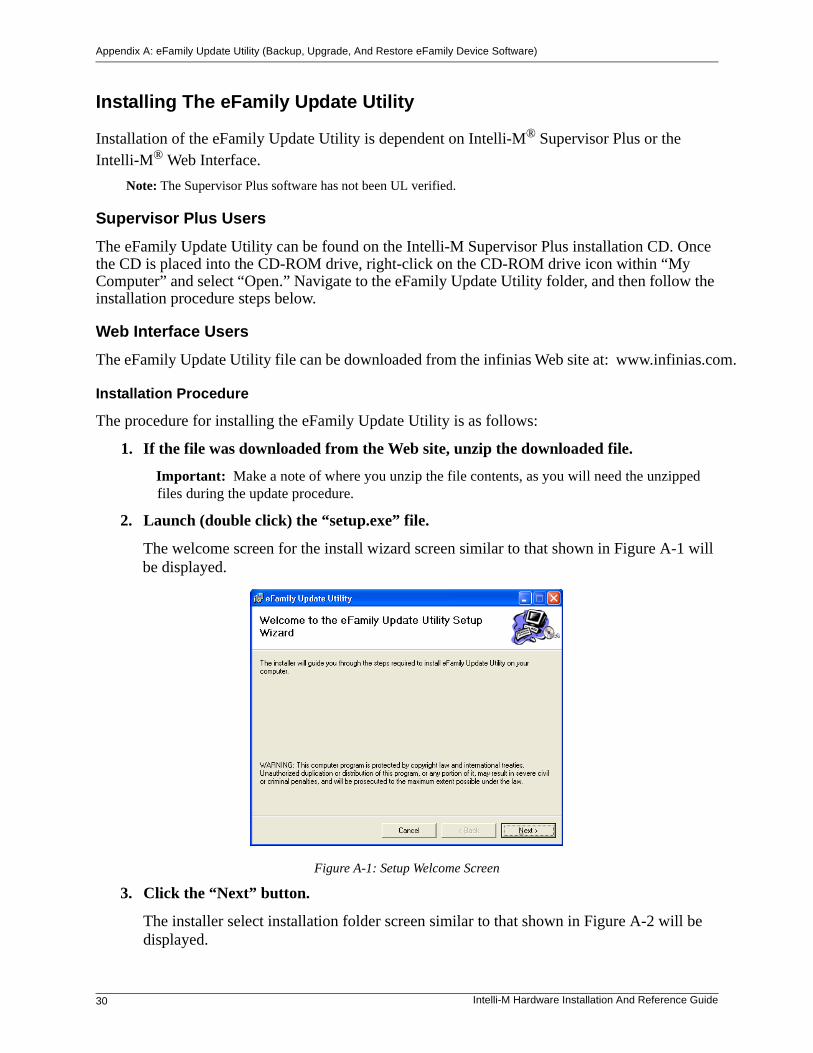
2. Launch (double click) the “setup.exe” file.
The welcome screen for the install wizard screen similar to that shown in Figure A-1 will be displayed.
Figure A-1: Setup Welcome Screen
3. Click the “Next” button.
The installer select installation folder screen similar to that shown in Figure A-2 will be displayed.
The eFamily Update Utility file can be downloaded from the infinias Web site at: www.infinias.com.
Appendix A: eFamily Update Utility (Backup, Upgrade, And Restore eFamily Device Software)
Intelli-M Hardware Installation And Reference Guide 31
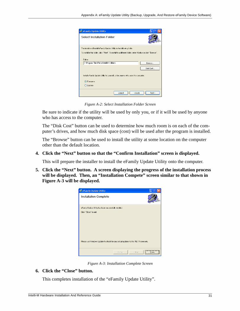
Figure A-2: Select Installation Folder Screen
Be sure to indicate if the utility will be used by only you, or if it will be used by anyone who has access to the computer.
The “Disk Cost” button can be used to determine how much room is on each of the com-puter’s drives, and how much disk space (cost) will be used after the program is installed.
The “Browse” button can be used to install the utility at some location on the computer other than the default location.
4. Click the “Next” button so that the “Confirm Installation” screen is displayed.
This will prepare the installer to install the eFamily Update Utility onto the computer.
5. Click the “Next” button. A screen displaying the progress of the installation process will be displayed. Then, an “Installation Compete” screen similar to that shown in Figure A-3 will be displayed.
Figure A-3: Installation Complete Screen
6. Click the “Close” button.
This completes installation of the “eFamily Update Utility”.
Appendix A: eFamily Update Utility (Backup, Upgrade, And Restore eFamily Device Software)
32 Intelli-M Hardware Installation And Reference Guide
Before Updating Your eFamily Device
To update an eFamily device, you must first gather the following information for the procedure:
• IP Address of the device you want to update
• Port number configured for communication(The default port number is 18777.)
• FTP Username and Password for that device (The default Username and Password is the word “admin” without the quotes.)
• Location of the update file
If you are unsure of the IP address for the eFamily device you plan to update, power cycle the device. As the device boots, the IP address will be signalled by the LEDs. Refer to the “Determining The Network IP Address Type” section within Chapter 2 of this manual for details on reading the IP address from an eFamily device.
eFamily Update Procedure
Perform the following steps to update an eFamily device:
Important: If Supervisor Plus is running, shut it down before launching the eFamily Update Utility.
Note: The Supervisor Plus software has not been UL verified.
>> eFamily Update Utility).
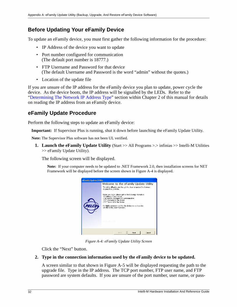
The following screen will be displayed.
Note: If your computer needs to be updated to .NET Framework 2.0, then installation screens for NET Framework will be displayed before the screen shown in Figure A-4 is displayed.
Figure A-4: eFamily Update Utility Screen
Click the “Next” button.
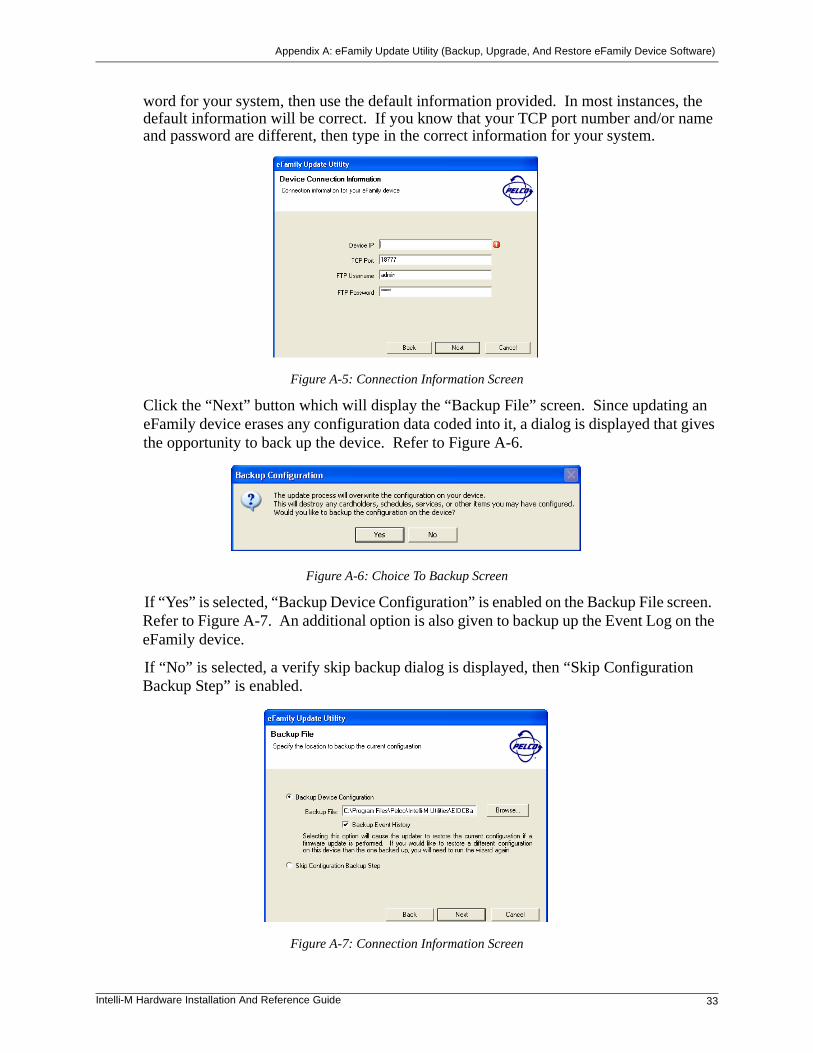
2. Type in the connection information used by the eFamily device to be updated.
A screen similar to that shown in Figure A-5 will be displayed requesting the path to the upgrade file. Type in the IP address. The TCP port number, FTP user name, and FTP password are system defaults. If you are unsure of the port number, user name, or pass-
1. Launch the eFamily Update Utility (Start >> All Programs >.> infinias >> Intelli-M Utilities
Appendix A: eFamily Update Utility (Backup, Upgrade, And Restore eFamily Device Software)
Intelli-M Hardware Installation And Reference Guide 33
word for your system, then use the default information provided. In most instances, the default information will be correct. If you know that your TCP port number and/or name and password are different, then type in the correct information for your system.
Figure A-5: Connection Information Screen
Click the “Next” button which will display the “Backup File” screen. Since updating an eFamily device erases any configuration data coded into it, a dialog is displayed that gives the opportunity to back up the device. Refer to Figure A-6.
Figure A-6: Choice To Backup Screen
If “Yes” is selected, “Backup Device Configuration” is enabled on the Backup File screen. Refer to Figure A-7. An additional option is also given to backup up the Event Log on the eFamily device.
If “No” is selected, a verify skip backup dialog is displayed, then “Skip Configuration Backup Step” is enabled.
Figure A-7: Connection Information Screen
Appendix A: eFamily Update Utility (Backup, Upgrade, And Restore eFamily Device Software)
34 Intelli-M Hardware Installation And Reference Guide
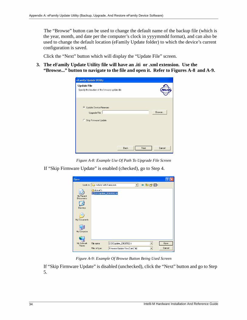
The “Browse” button can be used to change the default name of the backup file (which is the year, month, and date per the computer’s clock in yyyymmdd format), and can also be used to change the default location (eFamily Update folder) to which the device’s current configuration is saved.
Click the “Next” button which will display the “Update File” screen.
3. The eFamily Update Utility file will have an .iti or .xml extension. Use the “Browse...” button to navigate to the file and open it. Refer to Figures A-8 and A-9.
Figure A-8: Example Use Of Path To Upgrade File Screen
If “Skip Firmware Update” is enabled (checked), go to Step 4.
Figure A-9: Example Of Browse Button Being Used Screen
If “Skip Firmware Update” is disabled (unchecked), click the “Next” button and go to Step 5.
Appendix A: eFamily Update Utility (Backup, Upgrade, And Restore eFamily Device Software)
Intelli-M Hardware Installation And Reference Guide 35
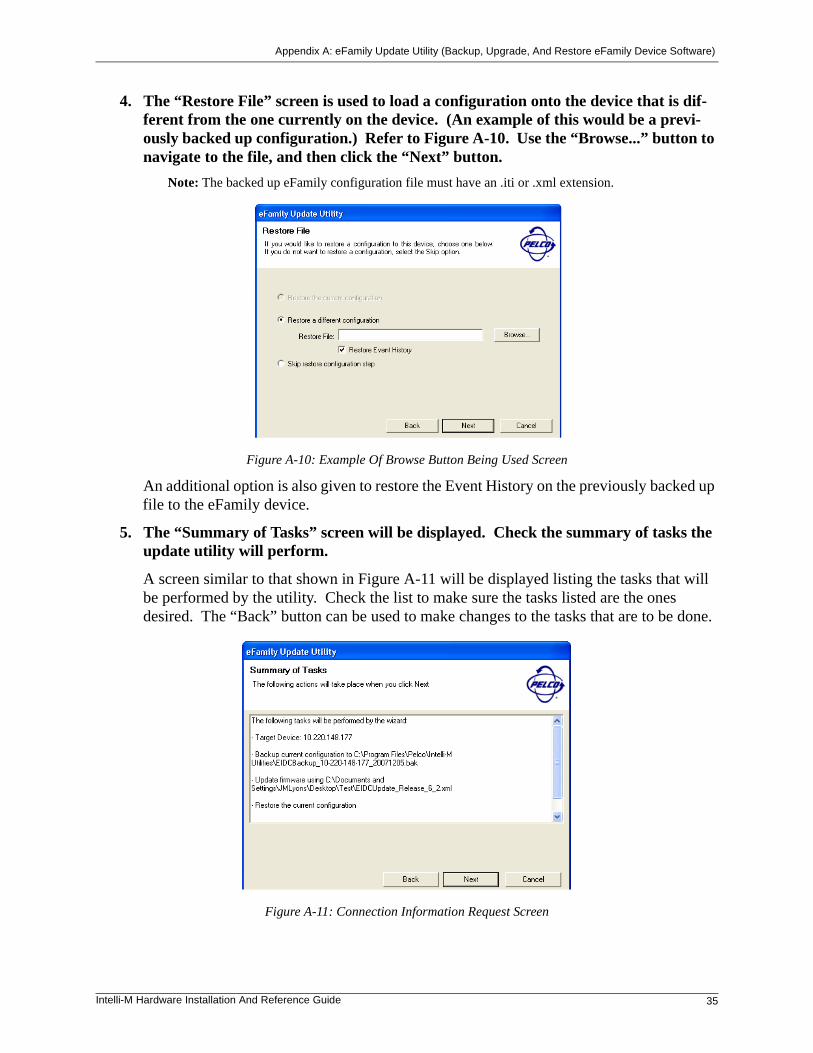
4. The “Restore File” screen is used to load a configuration onto the device that is dif-ferent from the one currently on the device. (An example of this would be a previ-ously backed up configuration.) Refer to Figure A-10. Use the “Browse...” button to navigate to the file, and then click the “Next” button.
Note: The backed up eFamily configuration file must have an .iti or .xml extension.
Figure A-10: Example Of Browse Button Being Used Screen
An additional option is also given to restore the Event History on the previously backed up file to the eFamily device.
5. The “Summary of Tasks” screen will be displayed. Check the summary of tasks the update utility will perform.
A screen similar to that shown in Figure A-11 will be displayed listing the tasks that will be performed by the utility. Check the list to make sure the tasks listed are the ones desired. The “Back” button can be used to make changes to the tasks that are to be done.
Figure A-11: Connection Information Request Screen

Appendix A: eFamily Update Utility (Backup, Upgrade, And Restore eFamily Device Software)
36 Intelli-M Hardware Installation And Reference Guide
6. Click the “Next” button to upgrade data to the eFamily device.
As the update proceeds, the screen will provide details about the update process. Refer to Figure A-12.
Figure A-12: Update In Process Screen
Once the update is complete, a screen similar to that shown in Figure A-13 will be displayed indicating that the update is complete.
Figure A-13: Update Complete Screen
Click the “Finish” button to close the utility, or click the back button to update a different eFamily device.
Appendix A: eFamily Update Utility (Backup, Upgrade, And Restore eFamily Device Software)
Intelli-M Hardware Installation And Reference Guide 37
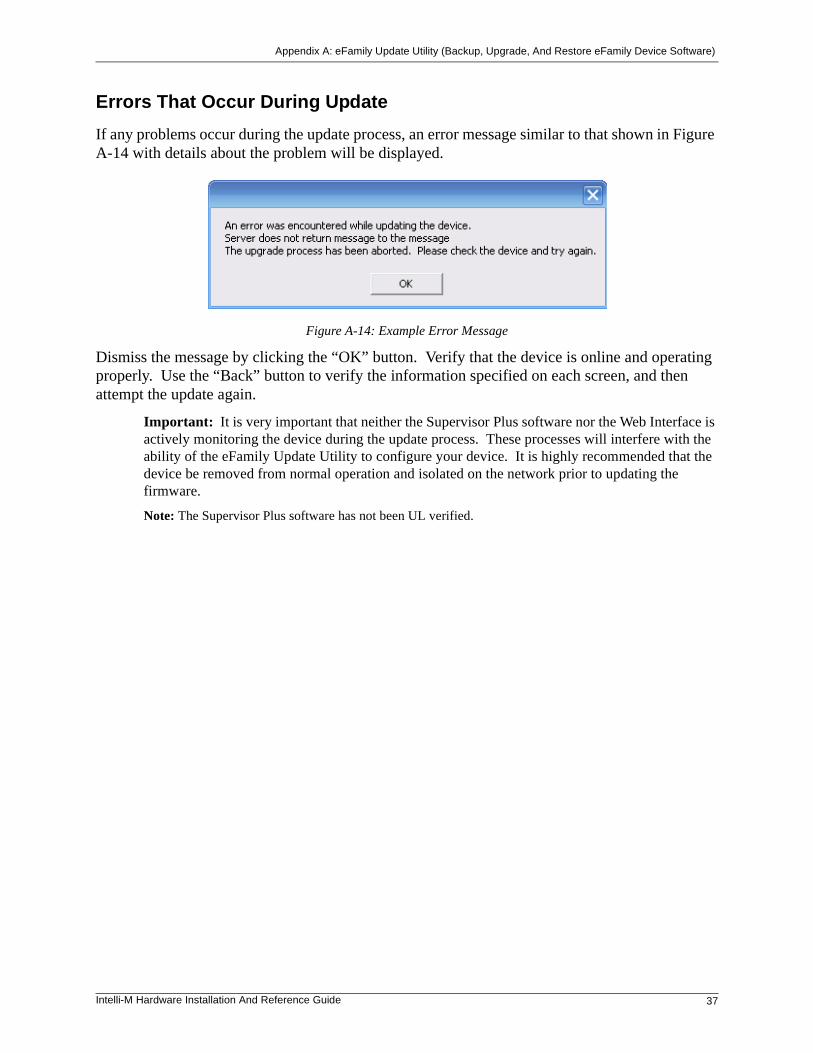
Errors That Occur During Update
If any problems occur during the update process, an error message similar to that shown in Figure A-14 with details about the problem will be displayed.
Figure A-14: Example Error Message
Dismiss the message by clicking the “OK” button. Verify that the device is online and operating properly. Use the “Back” button to verify the information specified on each screen, and then attempt the update again.
Important: It is very important that neither the Supervisor Plus software nor the Web Interface is actively monitoring the device during the update process. These processes will interfere with the ability of the eFamily Update Utility to configure your device. It is highly recommended that the device be removed from normal operation and isolated on the network prior to updating the firmware.
Note: The Supervisor Plus software has not been UL verified.

Appendix A: eFamily Update Utility (Backup, Upgrade, And Restore eFamily Device Software)
38 Intelli-M Hardware Installation And Reference Guide
Intelli-M Hardware Installation And Reference Guide 39
Appendix B: Demo Kit Wiring
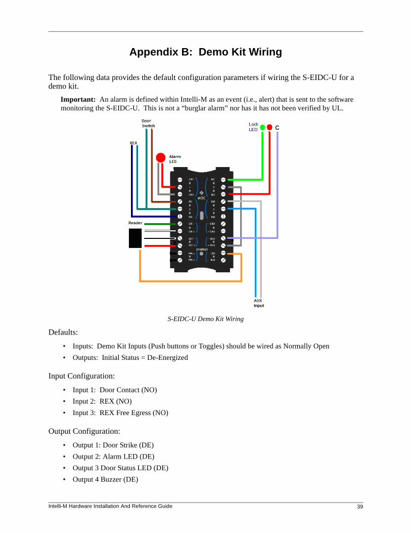
The following data provides the default configuration parameters if wiring the S-EIDC-U for a demo kit.
Important: An alarm is defined within Intelli-M as an event (i.e., alert) that is sent to the software monitoring the S-EIDC-U. This is not a “burglar alarm” nor has it has not been verified by UL.
S-EIDC-U Demo Kit Wiring
Defaults:
• Inputs: Demo Kit Inputs (Push buttons or Toggles) should be wired as Normally Open
• Outputs: Initial Status = De-Energized
Input Configuration:
• Input 1: Door Contact (NO)
• Input 2: REX (NO)
• Input 3: REX Free Egress (NO)
Output Configuration:
• Output 1: Door Strike (DE)
• Output 2: Alarm LED (DE)
• Output 3 Door Status LED (DE)
• Output 4 Buzzer (DE)
Appendix B: Demo Kit Wiring
40 Intelli-M Hardware Installation And Reference Guide
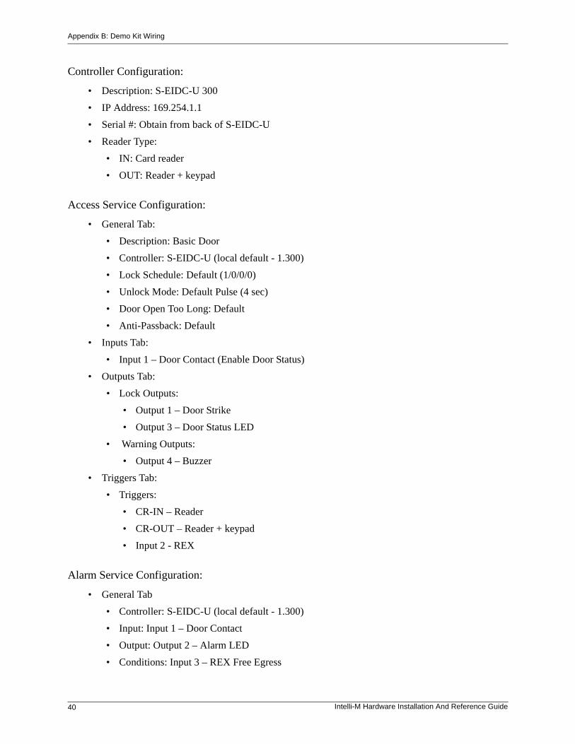
Controller Configuration:
• Description: S-EIDC-U 300
• IP Address: 169.254.1.1
• Serial #: Obtain from back of S-EIDC-U
• Reader Type:
• IN: Card reader
• OUT: Reader + keypad
Access Service Configuration:
• General Tab:
• Description: Basic Door
• Controller: S-EIDC-U (local default - 1.300)
• Lock Schedule: Default (1/0/0/0)
• Unlock Mode: Default Pulse (4 sec)
• Door Open Too Long: Default
• Anti-Passback: Default
• Inputs Tab:
• Input 1 – Door Contact (Enable Door Status)
• Outputs Tab:
• Lock Outputs:
• Output 1 – Door Strike
• Output 3 – Door Status LED
• Warning Outputs:
• Output 4 – Buzzer
• Triggers Tab:
• Triggers:
• CR-IN – Reader
• CR-OUT – Reader + keypad
• Input 2 - REX
Alarm Service Configuration:
• General Tab
• Controller: S-EIDC-U (local default - 1.300)
• Input: Input 1 – Door Contact
• Output: Output 2 – Alarm LED
• Conditions: Input 3 – REX Free Egress
Intelli-M Hardware Installation And Reference Guide 41
Appendix C: Intelli-M® Hardware Technical Specifications
The specifications for various hardware components of the Intelli-M system are given below.
Note: All specifications are subject to change without notice
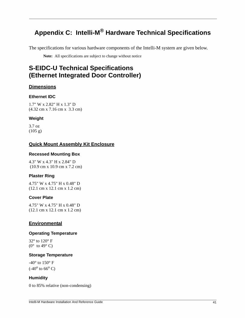
S-EIDC-U Technical Specifications(Ethernet Integrated Door Controller)
Dimensions
Ethernet IDC
1.7" W x 2.82" H x 1.3" D (4.32 cm x 7.16 cm x 3.3 cm)
Weight
3.7 oz (105 g)
Quick Mount Assembly Kit Enclosure
Recessed Mounting Box
4.3" W x 4.3" H x 2.84" D (10.9 cm x 10.9 cm x 7.2 cm)
Plaster Ring
4.75" W x 4.75" H x 0.48" D (12.1 cm x 12.1 cm x 1.2 cm)
Cover Plate
4.75" W x 4.75" H x 0.48" D (12.1 cm x 12.1 cm x 1.2 cm)
Environmental
Operating Temperature
32° to 120° F (0° to 49° C)
Storage Temperature
-40° to 150° F (-40o to 66o C)
Humidity
0 to 85% relative (non-condensing)
Appendix C: Intelli-M® Hardware Technical Specifications
42 Intelli-M Hardware Installation And Reference Guide
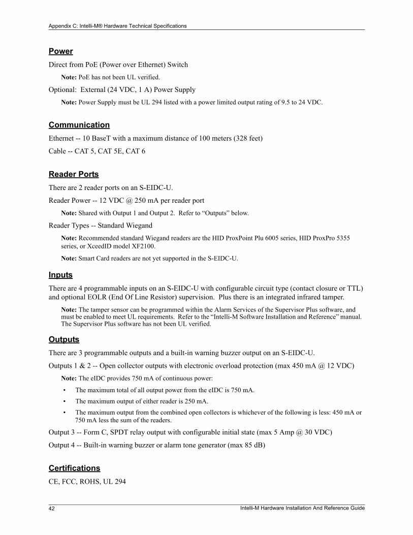
PowerDirect from PoE (Power over Ethernet) Switch
Note: PoE has not been UL verified.
Optional: External (24 VDC, 1 A) Power Supply
Note: Power Supply must be UL 294 listed with a power limited output rating of 9.5 to 24 VDC.
Communication Ethernet -- 10 BaseT with a maximum distance of 100 meters (328 feet)
Cable -- CAT 5, CAT 5E, CAT 6
Reader PortsThere are 2 reader ports on an S-EIDC-U.
Reader Power -- 12 VDC @ 250 mA per reader port
Note: Shared with Output 1 and Output 2. Refer to “Outputs” below.
Reader Types -- Standard Wiegand
Note: Recommended standard Wiegand readers are the HID ProxPoint Plu 6005 series, HID ProxPro 5355 series, or XceedID model XF2100.
Note: Smart Card readers are not yet supported in the S-EIDC-U.
InputsThere are 4 programmable inputs on an S-EIDC-U with configurable circuit type (contact closure or TTL) and optional EOLR (End Of Line Resistor) supervision. Plus there is an integrated infrared tamper.
Note: The tamper sensor can be programmed within the Alarm Services of the Supervisor Plus software, and must be enabled to meet UL requirements. Refer to the “Intelli-M Software Installation and Reference” manual. The Supervisor Plus software has not been UL verified.
OutputsThere are 3 programmable outputs and a built-in warning buzzer output on an S-EIDC-U.
Outputs 1 & 2 -- Open collector outputs with electronic overload protection (max 450 mA @ 12 VDC)
Note: The eIDC provides 750 mA of continuous power:
• The maximum total of all output power from the eIDC is 750 mA.
• The maximum output of either reader is 250 mA.
• The maximum output from the combined open collectors is whichever of the following is less: 450 mA or 750 mA less the sum of the readers.
Output 3 -- Form C, SPDT relay output with configurable initial state (max 5 Amp @ 30 VDC)
Output 4 -- Built-in warning buzzer or alarm tone generator (max 85 dB)
CertificationsCE, FCC, ROHS, UL 294
Appendix C: Intelli-M® Hardware Technical Specifications
Intelli-M Hardware Installation And Reference Guide 43
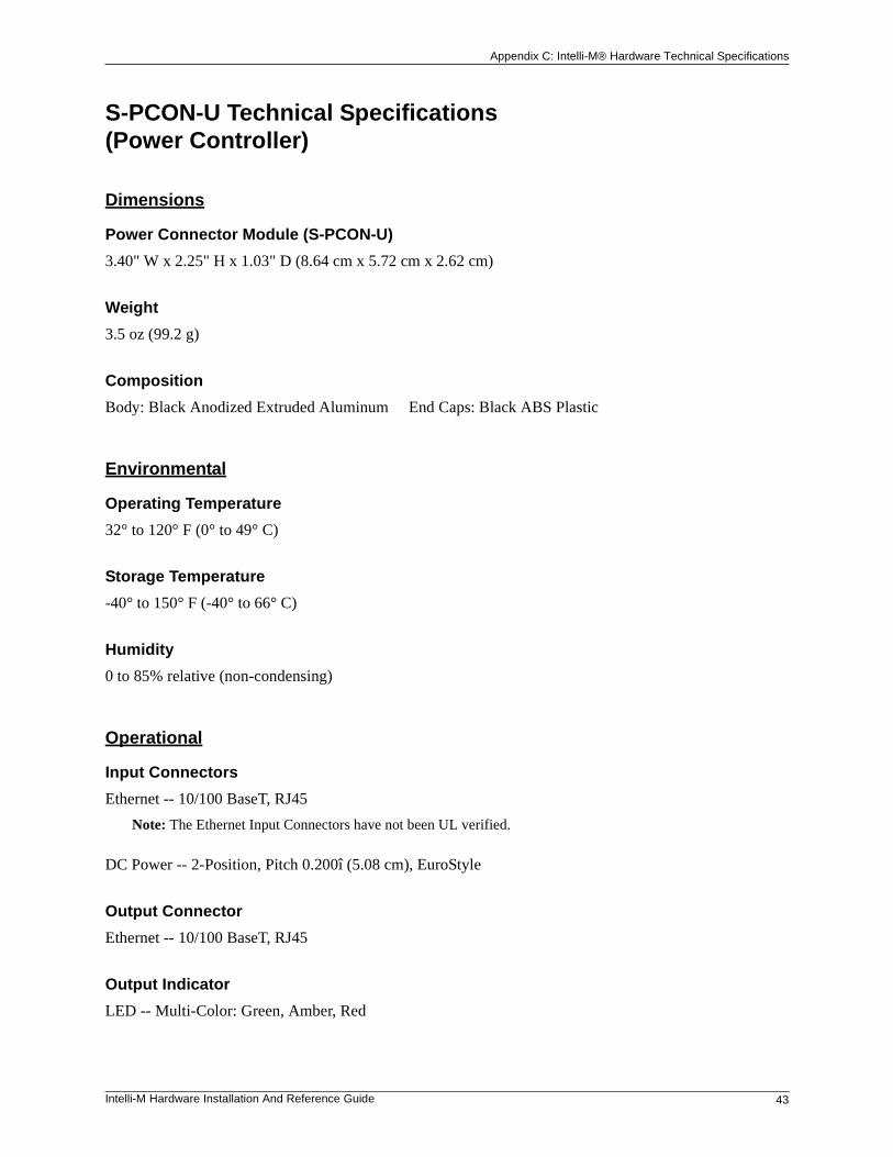
S-PCON-U Technical Specifications(Power Controller)
Dimensions
Power Connector Module (S-PCON-U)
3.40" W x 2.25" H x 1.03" D (8.64 cm x 5.72 cm x 2.62 cm)
Weight
3.5 oz (99.2 g)
Composition
Body: Black Anodized Extruded Aluminum End Caps: Black ABS Plastic
Environmental
Operating Temperature
32° to 120° F (0° to 49° C)
Storage Temperature
-40° to 150° F (-40° to 66° C)
Humidity
0 to 85% relative (non-condensing)
Operational
Input Connectors
Ethernet -- 10/100 BaseT, RJ45
Note: The Ethernet Input Connectors have not been UL verified.
DC Power -- 2-Position, Pitch 0.200î (5.08 cm), EuroStyle
Output Connector
Ethernet -- 10/100 BaseT, RJ45
Output Indicator
LED -- Multi-Color: Green, Amber, Red
Appendix C: Intelli-M® Hardware Technical Specifications
44 Intelli-M Hardware Installation And Reference Guide
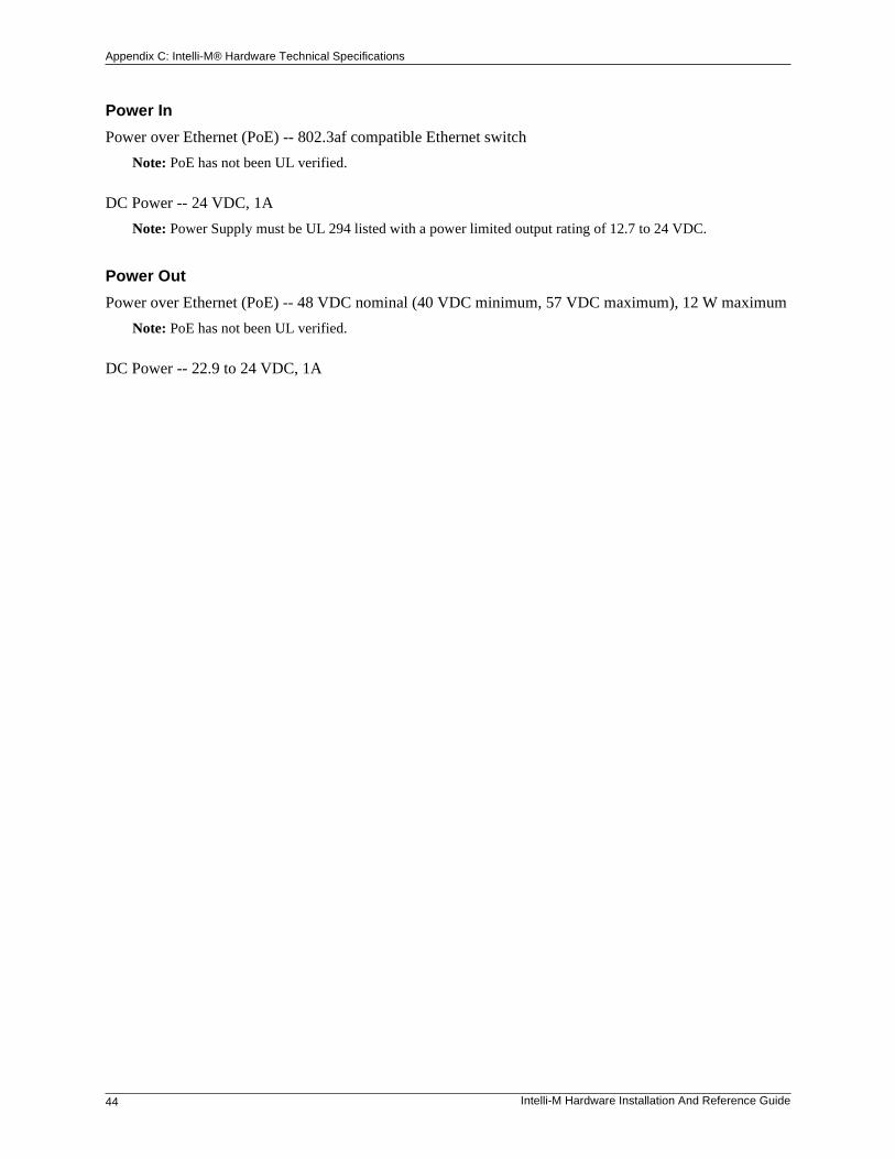
Power In
Power over Ethernet (PoE) -- 802.3af compatible Ethernet switch
Note: PoE has not been UL verified.
DC Power -- 24 VDC, 1A
Note: Power Supply must be UL 294 listed with a power limited output rating of 12.7 to 24 VDC.
Power Out
Power over Ethernet (PoE) -- 48 VDC nominal (40 VDC minimum, 57 VDC maximum), 12 W maximum
Note: PoE has not been UL verified.
DC Power -- 22.9 to 24 VDC, 1A
Appendix C: Intelli-M® Hardware Technical Specifications
Intelli-M Hardware Installation And Reference Guide 45
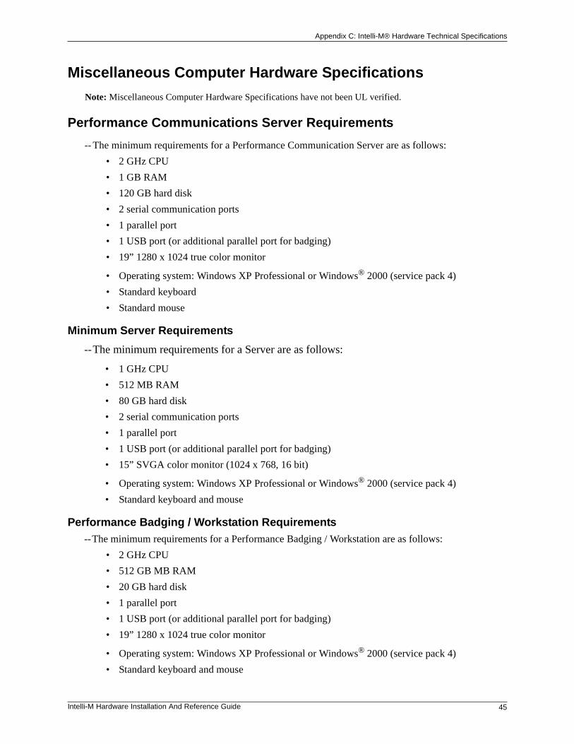
Miscellaneous Computer Hardware Specifications
Note: Miscellaneous Computer Hardware Specifications have not been UL verified.
Performance Communications Server Requirements
-- The minimum requirements for a Performance Communication Server are as follows:
• 2 GHz CPU
• 1 GB RAM
• 120 GB hard disk
• 2 serial communication ports
• 1 parallel port
• 1 USB port (or additional parallel port for badging)
• 19” 1280 x 1024 true color monitor
• Operating system: Windows XP Professional or Windows® 2000 (service pack 4)
• Standard keyboard
• Standard mouse
Minimum Server Requirements
--The minimum requirements for a Server are as follows:
• 1 GHz CPU
• 512 MB RAM
• 80 GB hard disk
• 2 serial communication ports
• 1 parallel port
• 1 USB port (or additional parallel port for badging)
• 15” SVGA color monitor (1024 x 768, 16 bit)
• Operating system: Windows XP Professional or Windows® 2000 (service pack 4)
• Standard keyboard and mouse
Performance Badging / Workstation Requirements--The minimum requirements for a Performance Badging / Workstation are as follows:
• 2 GHz CPU
• 512 GB MB RAM
• 20 GB hard disk
• 1 parallel port
• 1 USB port (or additional parallel port for badging)
• 19” 1280 x 1024 true color monitor
• Operating system: Windows XP Professional or Windows® 2000 (service pack 4)
• Standard keyboard and mouse
Appendix C: Intelli-M® Hardware Technical Specifications
46 Intelli-M Hardware Installation And Reference Guide
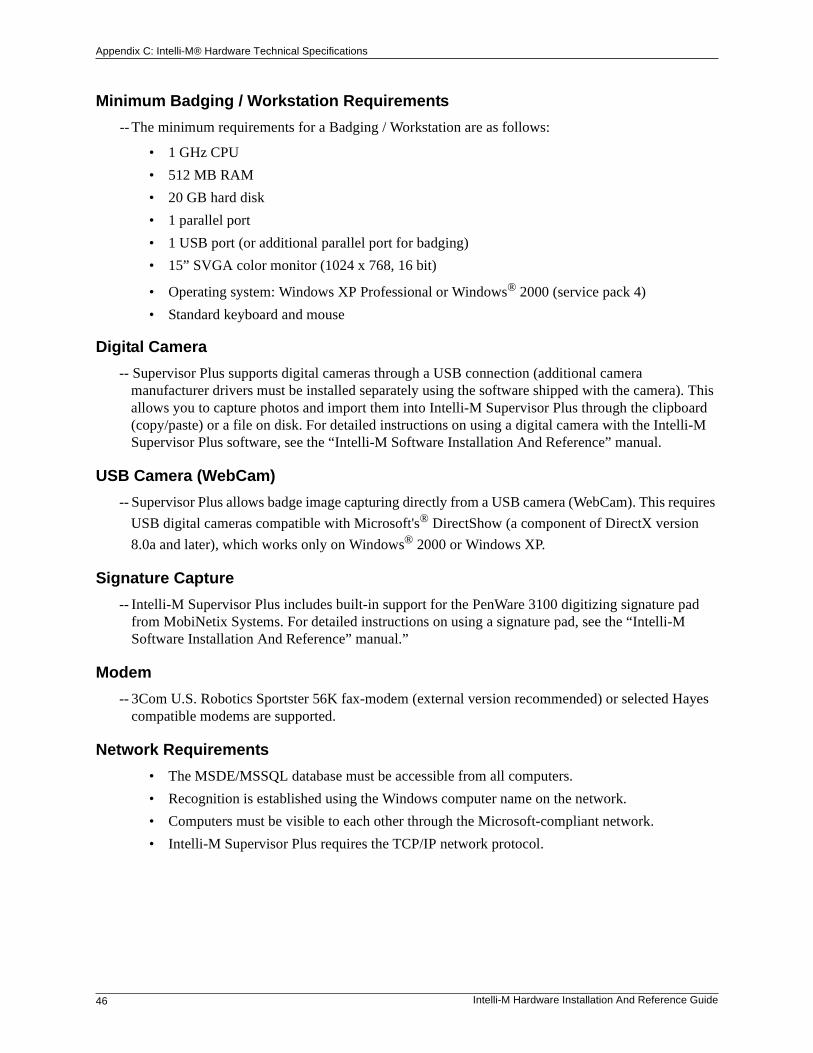
Minimum Badging / Workstation Requirements
-- The minimum requirements for a Badging / Workstation are as follows:
• 1 GHz CPU
• 512 MB RAM
• 20 GB hard disk
• 1 parallel port
• 1 USB port (or additional parallel port for badging)
• 15” SVGA color monitor (1024 x 768, 16 bit)
• Operating system: Windows XP Professional or Windows® 2000 (service pack 4)
• Standard keyboard and mouse
Digital Camera
-- Supervisor Plus supports digital cameras through a USB connection (additional camera manufacturer drivers must be installed separately using the software shipped with the camera). This allows you to capture photos and import them into Intelli-M Supervisor Plus through the clipboard (copy/paste) or a file on disk. For detailed instructions on using a digital camera with the Intelli-M Supervisor Plus software, see the “Intelli-M Software Installation And Reference” manual.
USB Camera (WebCam)
-- Supervisor Plus allows badge image capturing directly from a USB camera (WebCam). This requires
USB digital cameras compatible with Microsoft's® DirectShow (a component of DirectX version
8.0a and later), which works only on Windows® 2000 or Windows XP.
Signature Capture
-- Intelli-M Supervisor Plus includes built-in support for the PenWare 3100 digitizing signature pad from MobiNetix Systems. For detailed instructions on using a signature pad, see the “Intelli-M Software Installation And Reference” manual.”
Modem
-- 3Com U.S. Robotics Sportster 56K fax-modem (external version recommended) or selected Hayes compatible modems are supported.
Network Requirements
• The MSDE/MSSQL database must be accessible from all computers.
• Recognition is established using the Windows computer name on the network.
• Computers must be visible to each other through the Microsoft-compliant network.
• Intelli-M Supervisor Plus requires the TCP/IP network protocol.