Standards and guidelines for land surveying using gps ver 2.1.3
Upload
duongquynhCategory
view
226download
3
Development Guidelines
Page 1 of 115
Integration Development Guidelines
Architecture
Version: 2.15
Date: 2018-02-06
Document details
Reference: PIARQD017
Document Title: Integration Development Guidelines
Version: 2.15
Document name: PIARQD017 - GALP Integration Development Guidelines v2.15.docx

Development Guidelines
Page 2 of 115
Related Documentation
Reference Title Source
Revision History
Version Date Description Author
2.0 2014-04-01 Document creation Filipe Pateiro
2.1 2014-05-05 Added picture to Appendix C LogSubscriber Integration Process
Added Appendix D HTTP/SOAP Gateway
Updated Chapter 3.4.2 on Recommendations for Asynchronous Interface Implementation.
Updated 3.1 BW Project Template including the “repo2.TEMPLATE”
Filipe Pateiro
2.2 2014-05-19 Corrections on the Appendix D HTTP/SOAP Gateway about the WSDIL url.
Updated 4.3.5 Service Data Definition (SDD) about the physical location of the Schemas
Added Appendix E Migrating from Framework V1.
Filipe Pateiro
2.3 2014-05-23 Updated 4.6 Connecting to Back-end Applications, now explaining how to rightly use the application field and which application values are valid.
Added references to PIGENT15 – Error Configuration Document
Filipe Pateiro
2.4 2014-05-26 Updated 4.6 Connecting to Back-end Applications, explanation about how to use the “getSourceApplications” framework task to set the “Application”
Filipe Pateiro
2.5 2014-05-27 Updated 4.10 Framework Configuration. The text was changed to focus on the functionality instead of the tables DDL.
Updated 4.11 Unified Logging : The text was changed to focus on the functionality instead of the tables DDL.
Updated 0 JMS Messaging subchapters to give more detail on how the JMS messaging and starters should be used.
Added 4.3.2 Development Services patterns
Added 4.7 Timeouts
Added 4.12 Additional Framework Schemas
Filipe Pateiro
2.6 2014-05-30 Added 4.10.4.3 Specifying Additional Destinations (Filter on Header)
Added 4.10.4.4 Override routing rules (unique destination)
Added 4.10.5 Filtering Elements
Filipe Pateiro
2.7 2014-06-23 Restructuring the Additional Destinations and overwrite routing rules to a new chapter.
Added 4.9 Write to file system
Filipe Pateiro
2.8 2014-06-30 Update table with allowed applications on 4.6.3 Configuring the Application field
Filipe Pateiro
2.9 2014-09-17 Updated 3.4.2 Visio designs to include the Success Task on asynchronous invocations.
Updated Appendix B Creating a Service Schema DTL about the fixing steps of DTL Service Schemas
Updated Appendix E Migrating from Framework V1 in order to clarify Interface migration rules from V1 to V2
Filipe Pateiro
2.10 2014-10-24 Updated the allowed SAP Domain names that should be used on 4.6.3 Configuring the Application field
Filipe Pateiro
2.11 2015-01-30 Added the new functionalities that are available since the SharedLibrary 2.30, namely:
Updated 3.6.1 Framework Resources > Forward Task now lowers the JMS priority automatically
Updated 4.2.4 Updating Variables in real time to reflect the new functionality to Reset specific services configuration on the engines.
Update 4.4 Service Schemas . The header Input now as:
Filipe Pateiro

Development Guidelines
Page 3 of 115
Version Date Description Author
- a new element for correlate Tracking IDs with synchronous call over an asynchronous pattern.
- The Configuration Element is now available in order to set different configurations for each call. It’s use however must first be debated with the Architecture team
2.12 2016-11-04 Updated Appendix D HTTP/SOAP Gateway
Explain how the gateway works between the external HTTP endpoint and the internal JMS endpoint
Added subchapter on how to restrict access to services on a specific gateway
Added subchapter explaining that each gateway can be called in both Synchronous and Asynchronous mode.
Hugo Pascoalinho
2.13 2017-02-22 Updated Appendix D HTTP/SOAP Gateway to match new HTTP/SOAP Gateway
Hugo Pascoalinho
2.14 2017-06-14 Updated 4.3.6.3 Native Execution Codes Translation to further detail the code translation process
Hugo Pascoalinho
2.15 2018-02-05 Overall revision to update document to Galp’s current framework and guidelines
Hugo Pascoalinho

Development Guidelines
Page 4 of 115
Table of contents 1 Introduction ............................................................................................................................................................... 10
1.1 Scope ................................................................................................................................................................. 10 1.2 Document Organization ...................................................................................................................................... 10 1.3 Target readership, requirements of the reader ................................................................................................... 10 1.4 Distribution .......................................................................................................................................................... 10 1.5 Terms and abbreviations .................................................................................................................................... 11 1.6 Referenced Documents ...................................................................................................................................... 11
2 Development Environment ........................................................................................................................................ 12 2.1 Server-based Environment Landscape .............................................................................................................. 12
2.1.1 Environment Types ..................................................................................................................................... 12 2.1.2 Environment configuration .......................................................................................................................... 13 2.1.3 TIBCO Software Products .......................................................................................................................... 13 2.1.4 Recommended Developer Tools ................................................................................................................ 14 2.1.5 Libraries used ............................................................................................................................................. 16 2.1.6 Configuration on TIBCO Designer .............................................................................................................. 16 2.1.7 Configuration and Account Requests ......................................................................................................... 17
3 BW Project Setup and Structure ............................................................................................................................... 18 3.1 BW Project Template .......................................................................................................................................... 18 3.2 Encoding............................................................................................................................................................. 18 3.3 BW Project Structure .......................................................................................................................................... 18 3.4 Service and Interface Implementation ................................................................................................................ 19
3.4.1 Starters ....................................................................................................................................................... 21 3.4.2 Logical ........................................................................................................................................................ 22 3.4.3 Internal Service Call .................................................................................................................................... 27
3.5 Domain Processes ............................................................................................................................................. 28 3.6 Shared Resources and Design Time Libraries ................................................................................................... 30
3.6.1 Framework Resources ................................................................................................................................ 30 3.6.2 Design Time Libraries ................................................................................................................................. 32
3.7 Source Control .................................................................................................................................................... 34 4 Implementation Guidelines ........................................................................................................................................ 36
4.1 Naming conventions ........................................................................................................................................... 36 4.1.1 Services ...................................................................................................................................................... 36 4.1.2 Interfaces .................................................................................................................................................... 37 4.1.3 Processes ................................................................................................................................................... 37 4.1.4 Messaging .................................................................................................................................................. 37 4.1.5 Variables ..................................................................................................................................................... 37
4.2 Variable Usage ................................................................................................................................................... 38 4.2.1 Global Variables ......................................................................................................................................... 38 4.2.2 Process Variables ....................................................................................................................................... 39 4.2.3 Shared Variables ........................................................................................................................................ 40 4.2.4 Updating Variables in real time ................................................................................................................... 40
4.3 Integration Architecture....................................................................................................................................... 41 4.3.1 Service Design and Granularity .................................................................................................................. 41 4.3.2 Development Services patterns .................................................................................................................. 44 4.3.3 Standardized Message Bus ........................................................................................................................ 46 4.3.4 Common Object Model (COM) ................................................................................................................... 47 4.3.5 Service Data Definition (SDD) .................................................................................................................... 49

Development Guidelines
Page 5 of 115
4.3.6 Execution Codes ......................................................................................................................................... 51 4.4 Service Schemas ................................................................................................................................................ 55
4.4.1 Overview ..................................................................................................................................................... 55 4.4.2 Developing the Service Schemas ............................................................................................................... 61 4.4.3 XML Schemas on the Standardized Message Bus ..................................................................................... 62
4.5 Java Code .......................................................................................................................................................... 63 4.5.1 BusinessWorks Java code activity .............................................................................................................. 63 4.5.2 Third-party Libraries .................................................................................................................................... 63
4.6 Connecting to Back-end Applications ................................................................................................................. 63 4.6.1 Functional Services .................................................................................................................................... 63 4.6.2 Functional Interfaces .................................................................................................................................. 64 4.6.3 Configuring the Application field ................................................................................................................. 64
4.7 Timeouts ............................................................................................................................................................. 66 4.7.1 Paradigm timeout rules ............................................................................................................................... 66 4.7.2 Framework timeout handling....................................................................................................................... 67 4.7.3 Framework timeout usage .......................................................................................................................... 69
4.8 Checkpoints ........................................................................................................................................................ 69 4.9 Write to file system ............................................................................................................................................. 69
4.9.1 House Keeping ........................................................................................................................................... 70 4.10 Framework Configuration ................................................................................................................................... 70
4.10.1 Service Catalog .......................................................................................................................................... 70 4.10.2 Canonical Execution Codes ........................................................................................................................ 73 4.10.3 Service execution code translation ............................................................................................................. 74 4.10.4 Routing Rules ............................................................................................................................................. 78 4.10.5 Filtering Elements ....................................................................................................................................... 81
4.11 Unified Logging ................................................................................................................................................... 84 4.11.1 EAI_LOG_HEADER ................................................................................................................................... 84 4.11.2 EAI_LOG_DEBUG ...................................................................................................................................... 87 4.11.3 EAI_LOG_KEY ........................................................................................................................................... 88 4.11.4 EAI_LOG_DESTINATION .......................................................................................................................... 88
4.12 Additional Framework Schemas ......................................................................................................................... 89 4.12.1 TIBEH Schema ........................................................................................................................................... 89 4.12.2 TIBCOBAM Schema ................................................................................................................................... 89 4.12.3 LOGMON Schema ...................................................................................................................................... 89
4.13 JMS Messaging .................................................................................................................................................. 90 4.13.1 Security ....................................................................................................................................................... 90 4.13.2 Standards ................................................................................................................................................... 90 4.13.3 Subject Rules.............................................................................................................................................. 90 4.13.4 Service Implementation .............................................................................................................................. 91
4.14 Hawk Rules Development .................................................................................................................................. 92 4.14.1 Hawk Agent rules ........................................................................................................................................ 93 4.14.2 Product specific rules .................................................................................................................................. 93 4.14.3 Developing Hawk Rules .............................................................................................................................. 93
5 TIBCO Components .................................................................................................................................................. 94 5.1 Overview............................................................................................................................................................. 94 5.2 Component Naming ............................................................................................................................................ 94
5.2.1 BusinessWorks ........................................................................................................................................... 94 5.2.2 Adapters ..................................................................................................................................................... 95
Appendix A. Service development steps .............................................................................................................. 97 Appendix B. Creating a Service Schema DTL ...................................................................................................... 99 Appendix C. LogSubscriber Integration Process .............................................................................................. 102
Development Guidelines
Page 6 of 115
Appendix D. HTTP/SOAP Gateway...................................................................................................................... 106 Appendix E. Migrating from Framework V1 ....................................................................................................... 111
Development Guidelines
Page 7 of 115
Table of Figures Figure 1 –PRD environment configuration ................................................................................................................... 13 Figure 2 – List of Base File Alias ................................................................................................................................... 17 Figure 3 – BW project structure ..................................................................................................................................... 19 Figure 4 – BW Service and Interface Layering .................................................................................................................. 20 Figure 5 – Approved Service Starter Pattern ..................................................................................................................... 21 Figure 6 –Asynchronous Interface starter pattern ............................................................................................................. 22 Figure 7 –Synchronous Interface starter pattern ............................................................................................................... 22 Figure 8 – Interface logical pattern .................................................................................................................................... 23 Figure 9 – Routing Orchestration Pattern .......................................................................................................................... 24 Figure 10 – Normal Orchestration Pattern......................................................................................................................... 25 Figure 11 – Functional Service Pattern ............................................................................................................................. 26 Figure 12 – Intra-domain Service callouts ......................................................................................................................... 27 Figure 13 – Domain process ............................................................................................................................................. 28 Figure 14 – Domain processes ...................................................................................................................................... 29 Figure 15 – TFS Repository View ..................................................................................................................................... 35 Figure 16 – Repository Global Variables. .......................................................................................................................... 39 Figure 17 – BW Service Types .......................................................................................................................................... 42 Figure 18 – BW Service types ........................................................................................................................................... 44 Figure 19 – Service Deployment location .......................................................................................................................... 45 Figure 20 – Service Deployment location across split back-end applications ................................................................... 45 Figure 21 – Orchestration development ............................................................................................................................ 46 Figure 22 – Standardized Message Bus ........................................................................................................................... 47 Figure 23 – COM elements at design time ........................................................................................................................ 48 Figure 24 – Example of COM element “Imposto” .............................................................................................................. 49 Figure 25 – Graphical example of the SDD of the service “Documento” ........................................................................... 49 Figure 26 – SDD schemas at design time ......................................................................................................................... 50 Figure 27 – check end-system status codes framework task ............................................................................................ 53 Figure 28 – Header Schema ............................................................................................................................................. 56 Figure 29 – Message Data Schema ................................................................................................................................ 57 Figure 30 – SharedResources DTL ................................................................................................................................... 57 Figure 31 – Service Data Schema .................................................................................................................................... 61 Figure 32 – Framework Timeout algorithm. .................................................................................................................. 68 Figure 33 – Getting the Timeout value from the current Job Shared Variable .......................................................... 69 Figure 34 – EAI Error Service algorithm ........................................................................................................................ 77 Figure 35 – Destination filter elements.......................................................................................................................... 80 Figure 36 – Apply Filters framework task .......................................................................................................................... 82 Figure 37 – Sending all Data to Back-end System ............................................................................................................ 83 Figure 38 – Filtering the data before sending to the Back-End System ............................................................................ 84 Figure 39 – Adapter Types ................................................................................................................................................ 96 Figure 40 – Serviceschema DTL name and location .................................................................................................... 99 Figure 41 – Resources TAB on the DTL ........................................................................................................................ 99 Figure 42 – Browse and filter Internal Calls ................................................................................................................ 100 Figure 43 – Select services “Internal Calls” ............................................................................................................... 100 Figure 44 – LogSubscriber component architecture. ................................................................................................ 102 Figure 45 – HTTP/SOAP Gateway. ............................................................................................................................... 106 Figure 46 – removing eventLog on the End Task. ...................................................................................................... 112 Figure 47 – BusinessKeys framework task ................................................................................................................. 112 Figure 48 – BusinessKeys framework task ................................................................................................................. 113

Development Guidelines
Page 8 of 115
Figure 49 – Discover Source Application framework task ........................................................................................ 114 Figure 50 – Forward Message framework task ........................................................................................................... 114 Figure 51 – removing eventLog on the End Task. ...................................................................................................... 114

Development Guidelines
Page 9 of 115
Table of Tables Table 1 – Distribution list ................................................................................................................................................ 10 Table 2 – Terms and abbreviations ............................................................................................................................... 11 Table 3 – Referenced documents .................................................................................................................................. 11 Table 4 – TIBCO Software Products Overview ............................................................................................................. 14 Table 5 – Developer tools ............................................................................................................................................... 14 Table 6 – Service Framework base third party libraries .............................................................................................. 16 Table 7 – Service Framework extended third party libraries ....................................................................................... 16 Table 8 – Framework Resources ................................................................................................................................... 32 Table 9 – Design Time Libraries .................................................................................................................................... 34 Table 10 – Repositories and DTLs ................................................................................................................................. 34 Table 11 – Common Execution Codes .......................................................................................................................... 52 Table 12 – Domain and Service specific Execution Codes ......................................................................................... 53 Table 13 – Native Execution Codes translation ............................................................................................................ 54 Table 14 – HeaderInput and HeaderOutput description ............................................................................................... 60 Table 15 – Allowed Application configuration .............................................................................................................. 66 Table 16 – T_EAI_CATALOG configuration .................................................................................................................. 71 Table 17 – T_EAI_ERROR_CATALOG configuration ................................................................................................... 74 Table 18 – T_EAI_ERROR_SERVICE configuration ..................................................................................................... 75 Table 19 – T_EAI_ERROR_SERVICE configuration normalized ................................................................................. 76 Table 20 – T_EAI_ROUTING_RULE configuration ........................................................................................................ 78 Table 21 – T_EAI_ROUTING_DESTINATION configuration ......................................................................................... 79 Table 22 – RULE_TYPE field configuration ................................................................................................................... 80 Table 23 – Routing Rule configuration for a Filter Destination ................................................................................... 81 Table 24 – T_EAI_FILTERS table ................................................................................................................................... 82 Table 25 – EAI_LOG_HEADER logging table ................................................................................................................ 85 Table 26 – EAI_LOG_DEBUG logging table .................................................................................................................. 87 Table 27 – EAI _LOG_KEY logging table ....................................................................................................................... 88 Table 28 – EAI_LOG_DESTINTION table ....................................................................................................................... 89 Table 29 – JMS Naming Schemas .................................................................................................................................. 90 Table 30 – JMS Naming Rules ........................................................................................................................................ 91 Table 31 – TIBCO Component Name abbreviations ..................................................................................................... 94

Development Guidelines
Page 10 of 115
1 Introduction
Guidelines and best practices for the development ensure consistency and high quality of integration solutions, leading to efficient implementation and operation. This document provides guidelines for developers which may also form the basis for implementation reviews.
1.1 Scope
The scope of this document is to define the reference model and architecture used in integration solutions for GALP business units. Historically, the term EAI has been used as a synonym for integration solutions.
1.2 Document Organization
The document is structured according to the sequence of tasks a developer encounters during the implementation phase of integration projects.
Section 2 describes the setup of the development environment.
Section 3 introduces the setup of a new project within TIBCO BW.
Section 4 provides guidelines for the BW based development.
Section 5 overviews the main TIBCO components at deploy time.
Section 6 introduces the testing required by the developer.
1.3 Target readership, requirements of the reader
This document targets developers, designers and architects working in GALP. The document assumes an
understanding of GALP Integration Architecture as well as knowledge in Tibco BusinessWorks based
development.
1.4 Distribution
This document has been distributed within GALP to:
Name Title Company Date of Issue Version
Table 1 – Distribution list
Development Guidelines
Page 11 of 115
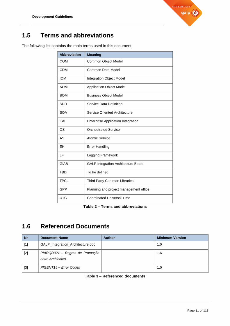
1.5 Terms and abbreviations
The following list contains the main terms used in this document.
Abbreviation Meaning
COM Common Object Model
CDM Common Data Model
IOM Integration Object Model
AOM Application Object Model
BOM Business Object Model
SDD Service Data Definition
SOA Service Oriented Architecture
EAI Enterprise Application Integration
OS Orchestrated Service
AS Atomic Service
EH Error Handling
LF Logging Framework
GIAB GALP Integration Architecture Board
TBD To be defined
TPCL Third Party Common Libraries
GPP Planning and project management office
UTC Coordinated Universal Time
Table 2 – Terms and abbreviations
1.6 Referenced Documents
Nr Document Name Author Minimum Version
[1] GALP_Integration_Architecture.doc 1.0
[2] PIARQD021 – Regras de Promoção
entre Ambientes
1.6
[3] PIGENT15 – Error Codes 1.0
Table 3 – Referenced documents

Development Guidelines
Page 12 of 115
2 Development Environment
This chapter provides background to and instructions for the setup of the personal development environment. Each developer is usually assigned a personal workstation or laptop which requires installation and configuration in order to be effective and efficient in the integration work at GALP.
2.1 Server-based Environment Landscape
While the focus of this section is on the personal development environment, this chapter outlines the overall environment landscape as background information.
2.1.1 Environment Types
There are a set of Tibco environments within GALP. In addition to a developer’s personal workstation environment, the following server-based types of environments are commonly known:
DEV: development environment dedicated to integration projects
QUA ISOLATED: integration test environment used for component integration testing, dedicated to integration projects and managed by the project and maintenance teams
QUA CONSOLIDATED: test environment for consolidated component testing with the packages that will be deployed in Production
PRD: cross project production environment
Additional environments may be set up for specific purposes such as training, demos, etc. The above TIBCO test environments normally provide connectivity to the corresponding environments of back-end applications. Note however that back-end application environments may be structured differently, in particular concerning the test environments and its availability of meaningful test data. Note: For more information about on how to promote the development throughout the environments please check the document “PIARQD021 – Regras de Promoção entre Ambientes”

Development Guidelines
Page 13 of 115
2.1.2 Environment configuration
Each environment consists of multiple servers with the following configuration:
- Interior SOA servers are based on Linux Redhat and designated to support specific software
Packages.
- Interior BAM servers are based on Linux Redhat and contain all necessary BAM software
- Web BAM servers are based on Linux Redhat and contain the necessary web servers (IIS
and apache) as well as the TIBCO required software
- Spotfire and EWU servers are based on Windows and contain the necessary web servers
(IIS and apache) as well as the TIBCO required software
- There is a single DMZ server based on windows that assures security between outside
systems and internal services
JMS
TIBCO EMS Appliance
TIBCO EMS Appliance
Solaris 10
Server 1
TIBCO Adapter for DB
TIBCO Adapter for SAP
TIBCO Adapter for Siebel
TIBCO Business Works
TIBCO Administrator
TIBCO Business Connect
Solaris 10
Server 2
TIBCO Adapter for DB
TIBCO Adapter for SAP
TIBCO Adapter for Siebel
TIBCO Business Works
TIBCO Administrator
TIBCO Business Connect
Linux Redhat 6
Server 1
TIBCO Business Events
TIBCO Spotfire
Linux Redhat 6
Server 2
TIBCO Business Events
TIBCO Spotfire
Windows Server 2008
TIBCO Spotfire webplayer
TIBCO RTview
Rendezvous
Rendezvous
TIBCO Business Connect
DMZ
Figure 1 –PRD environment configuration
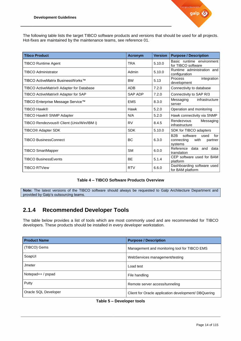
2.1.3 TIBCO Software Products
DEV 1 - TIBCO Software Products
Developers may only use the TIBCO software products and versions depicted in the below list. Deviations from the product roadmap require an explicit approval by GALP.
Nevertheless the version of the products must be confirmed by the project with the Architecture Department of Galp, prior to installation
Development Guidelines
Page 14 of 115
The following table lists the target TIBCO software products and versions that should be used for all projects. Hot-fixes are maintained by the maintenance teams, see reference 01.
Tibco Product Acronym Version Purpose / Description
TIBCO Runtime Agent TRA 5.10.0 Basic runtime environment for TIBCO software
TIBCO Administrator Admin 5.10.0 Runtime administration and configuration
TIBCO ActiveMatrix BusinessWorks™ BW 5.13 Process integration development
TIBCO ActiveMatrix® Adapter for Database ADB 7.2.0 Connectivity to database
TIBCO ActiveMatrix® Adapter for SAP SAP ADP 7.2.0 Connectivity to SAP R/3
TIBCO Enterprise Message Service™ EMS 8.3.0 Messaging infrastructure server
TIBCO Hawk® Hawk 5.2.0 Operation and monitoring
TIBCO Hawk® SNMP Adapter N/A 5.2.0 Hawk connectivity via SNMP
TIBCO Rendezvous® Client (Unix/Win/IBM i) RV 8.4.5 Rendezvous Messaging infrastructure
TIBCO® Adapter SDK SDK 5.10.0 SDK for TIBCO adapters
TIBCO BusinessConnect BC 6.3.0 B2B software used for connecting with partner systems
TIBCO SmartMapper SM 6.0.0 Reference data and data translation
TIBCO BusinessEvents BE 5.1.4 CEP software used for BAM platform
TIBCO RTView RTV 6.6.0 Dashboarding software used for BAM platform
Table 4 – TIBCO Software Products Overview
Note: The latest versions of the TIBCO software should always be requested to Galp Architecture Department and
provided by Galp’s outsourcing teams.
2.1.4 Recommended Developer Tools
The table below provides a list of tools which are most commonly used and are recommended for TIBCO developers. These products should be installed in every developer workstation.
Product Name Purpose / Description
(TIBCO) Gems Management and monitoring tool for TIBCO EMS
SoapUI WebServices management/testing
Jmeter Load test
Notepad++ / pspad File handling
Putty Remote server access/tunneling
Oracle SQL Developer Client for Oracle application development/ DBQuering
Table 5 – Developer tools

Development Guidelines
Page 15 of 115

Development Guidelines
Page 16 of 115
2.1.5 Libraries used
DEV 2 – Libraries
Developers may only use third party libraries approved by GALP and TIBCO. Deviations from the roadmap products require an explicit approval.
The products and versions within the roadmap have been agreed between GALP, vendors and suppliers. The tpcl libraries needed for running the base TIBCO Service Framework are:
Library Purpose / Description
ojdbc5.jar Oracle jdbc classes for DB connectivity
Custom.jar Only for Business Events projects. Custom functions needed to develop and test BE projects
Table 6 – Service Framework base third party libraries
The tpcl libraries needed for running extended functionalities provided by the TIBCO Service Framework are:
Library Purpose / Description Mandatory when / on
factElect.jar Used on Factura Electrónica Factura Electronica
InterfaceTIBCOIXOS.jar IXOS own API used to communicate via HTTP with IXOS Using IXOS API
Table 7 – Service Framework extended third party libraries
These libraries are located on TFS “/APP TIBCO CONS/Bibliotecas/5.13/ExternalLibraries” and will be made
available to the project on the start of the project development phase.
2.1.6 Configuration on TIBCO Designer
The figure below provides the list of File Alias that must be configured in the TIBCO Designer, by the TIBCO
developers, for the base TIBCO Service Framework:

Development Guidelines
Page 17 of 115
Figure 2 – List of Base File Alias
NOTE: The name of each projlib can change based on its version. As such the Project should always used
the most advanced one that will be provided by the GALP Maintenance teams
2.1.7 Configuration and Account Requests
2.1.7.1 Administration access for workstation
If necessary, administrative access for the GALP workstation should be request to GALP DSI.
2.1.7.2 TFS account
TFS is the standard repository for all integration projects within GALP. This is a centralized repository located in:
Server URL: getfs02:8080/tfs
Path: $/<PROJECT NAME>/Tibco/FrameworkV2
User: <Your GALP user>
The recommended client applications for TFS are Eclipse and Visual Studio both with Team Foundation Server extensions/plugins.

Development Guidelines
Page 18 of 115
3 BW Project Setup and Structure
3.1 BW Project Template
DEV 3 – BW project template
Developers must use the latest version of the BW project template to create a new project. Whenever a new project is created, the developer should check for the latest version of the template.
Currently the latest version of the Framework can be seen in the repo2.TEMPLATE project.
The project should ask to access this BW project/repository in read-only mode to see a real-life example of a
project in production using the latest framework features. This request should be made to Galp’s Architecture
department and fulfilled by Galp’s outsourcing teams.
3.2 Encoding
The BW template defines UTF-8 as TIBCO message encoding.
3.3 BW Project Structure
The BW project template creates a project with the following top-level folders:
AESchemas: standard BW folder used for schemas defined by Tibco products. This folder should not be manually changed by any developer.
BusinessDomain/<DOMAIN> (DOMAIN to be replaced): see below
DeploymentResources: this folder should contain all deployment artifacts, i.e. ear files.
The BusinessDomain/DOMAIN folder is where the related services, interfaces and processes implementation is done.

Development Guidelines
Page 19 of 115
Figure 3 – BW project structure The DOMAIN contains sub-folders:
BusinessResources: Business domain common resources used across services, interfaces and processes implementations.
Any development made available on this folder can only be used by services/processes/interfaces of the same Domain it belongs to
Services: Service implementation folder. All atomic or orchestrated services belonging to the
component will be implemented here. The structure is as above.
Interfaces: Interface implementation folder. All interfaces belonging to the component will be
implemented here. The structure is as above.
Processes: Process implementation folder. All processes belonging to the component will be
implemented here. The structure is as above.
Within each resource folder (Service, Interface or Process), there must be: - a _ServiceResources/Data folder with the respective Data.xsd that contain the input and
output schemas - a folder for each Service operation where several sub-folders specific for this operation
can exist. - Inside each operation there are always a ‘starter.process’, a ‘logical.process’ and a
‘internalCall’ process (if required) in order to respectively: handle the protocol, perform the business logic, and allow inner calls from other services.
3.4 Service and Interface Implementation
Implementation should always follow the same structure and construct. In addition to the logical layering defined below, other folders exist for shared resources, sub-processes, unit test.
DEV 4 – BW service implementation structure
BW service implementations must have three levels: Starter, Main and Logical. Additional layers (for example: sub processes) may be used if required and must be clearly identified.
Development Guidelines
Page 20 of 115
The splitting of transport and business logic makes it easier to:
Implement and maintain reusable services/components like exception handling and logging
Manage environment configurations
Establish reusable components
Maintain components
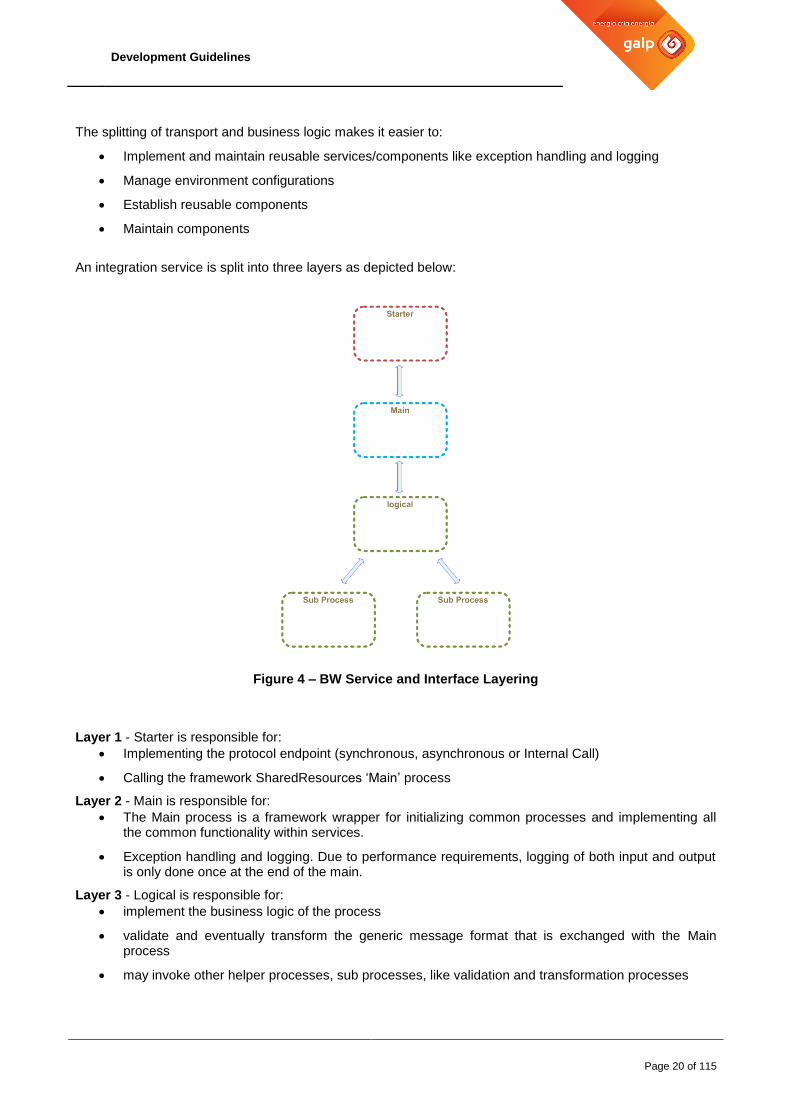
An integration service is split into three layers as depicted below:
Figure 4 – BW Service and Interface Layering
Layer 1 - Starter is responsible for:
Implementing the protocol endpoint (synchronous, asynchronous or Internal Call)
Calling the framework SharedResources ‘Main’ process
Layer 2 - Main is responsible for:
The Main process is a framework wrapper for initializing common processes and implementing all the common functionality within services.
Exception handling and logging. Due to performance requirements, logging of both input and output is only done once at the end of the main.
Layer 3 - Logical is responsible for:
implement the business logic of the process
validate and eventually transform the generic message format that is exchanged with the Main process
may invoke other helper processes, sub processes, like validation and transformation processes
Development Guidelines
Page 21 of 115
Unless specifically necessary, no layer should implement any of the tasks that are already handled on the previous layer (ex: Logical layer should not do log tasks nor catching errors)
3.4.1 Starters
DEV 5 – BW service starters
The Starter Process will contain just the necessary in order to connect from the desired Protocol/Transport to the Main process and back (reply) and perform exception handling and logging.
The framework already supplies a starter for service implementation over SOAP/JMS.
Unless previously approved by GALP, no code should ever be added to a service starter when developing a service
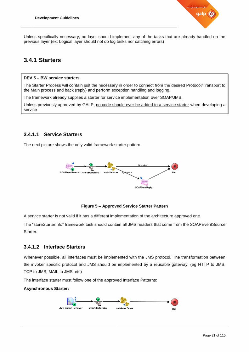
3.4.1.1 Service Starters
The next picture shows the only valid framework starter pattern.
Figure 5 – Approved Service Starter Pattern
A service starter is not valid if it has a different implementation of the architecture approved one.
The “storeStarterInfo” framework task should contain all JMS headers that come from the SOAPEventSource
Starter.
3.4.1.2 Interface Starters
Whenever possible, all interfaces must be implemented with the JMS protocol. The transformation between
the invoker specific protocol and JMS should be implemented by a reusable gateway. (eg HTTP to JMS,
TCP to JMS, MAIL to JMS, etc)
The interface starter must follow one of the approved Interface Patterns:
Asynchronous Starter:
Development Guidelines
Page 22 of 115
Figure 6 –Asynchronous Interface starter pattern
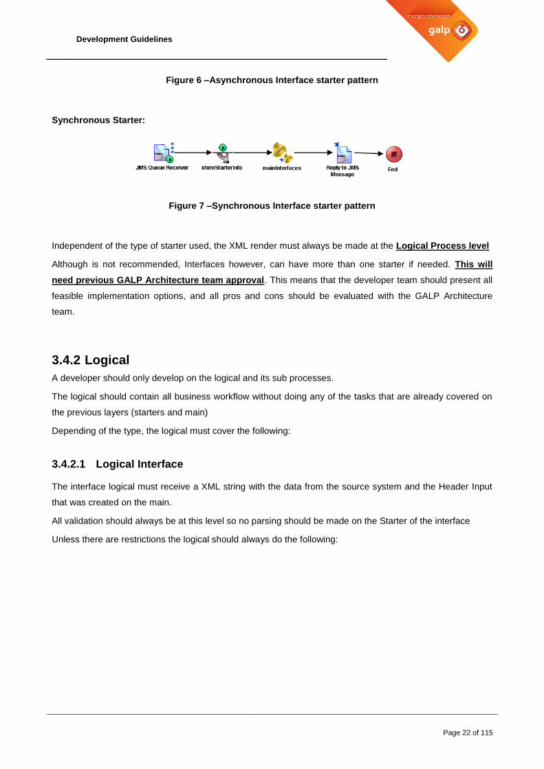
Synchronous Starter:
Figure 7 –Synchronous Interface starter pattern
Independent of the type of starter used, the XML render must always be made at the Logical Process level
Although is not recommended, Interfaces however, can have more than one starter if needed. This will
need previous GALP Architecture team approval. This means that the developer team should present all
feasible implementation options, and all pros and cons should be evaluated with the GALP Architecture
team.
3.4.2 Logical
A developer should only develop on the logical and its sub processes.
The logical should contain all business workflow without doing any of the tasks that are already covered on
the previous layers (starters and main)
Depending of the type, the logical must cover the following:
3.4.2.1 Logical Interface
The interface logical must receive a XML string with the data from the source system and the Header Input
that was created on the main.
All validation should always be at this level so no parsing should be made on the Starter of the interface
Unless there are restrictions the logical should always do the following:

Development Guidelines
Page 23 of 115
Start
Parse incoming XML
message
Re-Initialize the Header
with the data that come
from the source system
Map to target Coporate
service
Set the Business Keys
Use “Forward
Message” to publish
the data
Use iCall to request
the data
End
No
Is it
assyncronous?
Yes
Map the reply
Use Success Task
Figure 8 – Interface logical pattern
Note: When the Interface calls an Asynchronous service, if the interface and the Orchestration Service (CORP) reside
on the same repository (same EAR), it’s recommended to use the iCall instead of the forward message task.
This will improve performance and will do a better Infra-structure resource management.
For more information about how to configure Functional Interfaces and the Back-End application information
check chapter 4.6 Connecting to Back-end Applications

Development Guidelines
Page 24 of 115
3.4.2.2 Logical Service
The service implementation will change depending if it is an Orchestration (CORP) service or a Functional
(DOMAIN) one.
Orchestration services, like the name says, are responsible to orchestrate the business logic by invoking one
or more Functional services. This will mean that Orchestration services can’t invoke external end-systems.
Whenever possible the services should follow one of the following patterns:
Routing Orchestration:
This pattern is used to publish Data from a Source System to one or more several end-systems. It
just needs to identify the Business Keys necessary for the routing mechanisms to work.
Start
Set the Business Keys
Use “Route and
Forward” to Identify
destinations and
publish the data
End
Use Success Task
Figure 9 – Routing Orchestration Pattern
Normal Orchestration:
This pattern is used when specific business logic is needed for both Asynchronous and Synchronous
type services. The thing to take in consideration is that usually the errors are not raised at this level;
the errors occur at the Functional Service level, on the data exchange with the end-systems.

Development Guidelines
Page 25 of 115
As such, this pattern is responsible to set all Business Keys that are necessary to identify the
request, develop the Business Logic and return the success of the last functional error received.
Start
Set the Business Keys
End
Map the output
Invoke or publish to Functional Services in workflow order
Figure 10 – Normal Orchestration Pattern
Functional Service:
This pattern will fill the needs of most Domain Functional Services as such a similar pattern should
be followed to all developments of Functional (Domain) Services.
Since the Business Keys were already set on the Orchestration (CORP) service, the business Keys
at this level are optional and should only be used if the end-system replies with additional information
that is useful for business searches.
Depending if the connection with the end-system is synchronous or asynchronous, the Framework
tasks to use also differ.

Development Guidelines
Page 26 of 115
Translate End-System
Status Codes to
Common Execution
Codes
Start
Use Success Task
End
No
End-system
return status
codes?
Yes
Map the reply to
Common Format
Map to end-system
format
Invoke End-system
End-system
return Additional
Business
Information?
Set the missing
Business Keys
Yes
No
Figure 11 – Functional Service Pattern
For more information about how to configure Functional Services and the Back-End application
information check chapter 4.6 Connecting to Back-end Applications

Development Guidelines
Page 27 of 115
3.4.3 Internal Service Call
All synchronous calls of services that belong to the Framework must be called using the iCall (Internal
Call) starter. This method will ease the development since the task guarantees the inputs and outputs of the
target service while optimizing the workload on EMS server (and in BW itself) since it will detect
automatically when the service exists on the same repository (EAR).
The [internalCall] process exists next to the starter and should be propagated via DTL to all repositories that
want to invoke it (see Chapter 3.6.2 Design Time Libraries)
DEV 6 – [internalCall] process
The [internalCall] process is a special starter that must exist in all services.
This process decides, based on engine runtime information and based on service catalogue information, if the call to a service (e.g. in an orchestration) can be performed internally or in alternative, via a remote JMS request reply.
Figure 12 – Intra-domain Service callouts
Starter B
Main
logical
Sub Process Sub Process
Starter A
Main
logical
Sub Process Sub Process
[icall] Starter B
Development Guidelines
Page 28 of 115
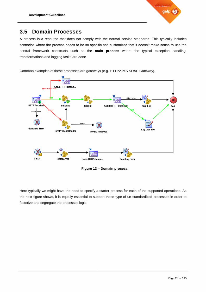
3.5 Domain Processes
A process is a resource that does not comply with the normal service standards. This typically includes
scenarios where the process needs to be so specific and customized that it doesn’t make sense to use the
central framework constructs such as the main process where the typical exception handling,
transformations and logging tasks are done.
Common examples of these processes are gateways (e.g. HTTP2JMS SOAP Gateway).
Figure 13 – Domain process
Here typically we might have the need to specify a starter process for each of the supported operations. As
the next figure shows, it is equally essential to support these type of un-standardized processes in order to
factorize and segregate the processes logic.

Development Guidelines
Page 29 of 115
Figure 14 – Domain processes
Development Guidelines
Page 30 of 115
3.6 Shared Resources and Design Time Libraries
This component holds all the artifacts, organized by several libraries that should be reused by the integration
components:
Framework Resources – Resources meant to be used by developers when building logical
processes. These resources hold standardized operations, such as Interpreters (e.g. message
parsers and renders), exception categorization, etc. This means that only these framework artifacts
should be used by developers in their processes.
Shared Resources – Resources that hold common logic to the entire integration framework. These
resources hold artifacts that cannot be used randomly at the logical process level. They have in
fact specific functionalities that abstract common operations to the development team, allowing it to
focus on the functional implementation of their logical processes.
Common Data Model – Business schemas that represent the business entities and the information
they hold in a Canonical format.
It is expected that more shared libraries can be developed in order to respond to new requirements.
This layout allows centralization of common tasks potentiating the SOA architecture. Typical tasks like
exception handling and categorization, logging, etc. are available to be re-used. Integration platform
operations and maintenance is also simplified by this approach.
All common resources are maintained by the Service Framework team. This doesn’t mean that it cannot be
extended by developer teams. They should in fact be proactive and suggest enhancements and even
provide source code to be included as common framework resources.
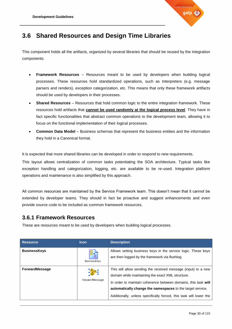
3.6.1 Framework Resources
These are resources meant to be used by developers when building logical processes.
Resource Icon Description
BusinessKeys
Allows setting business keys in the service logic. These keys
are then logged by the framework via flushlog.
ForwardMessage
This will allow sending the received message (input) to a new
domain while maintaining the exact XML structure.
In order to maintain coherence between domains, this task will
automatically change the namespaces to the target service.
Additionally, unless specifically forced, this task will lower the

Development Guidelines
Page 31 of 115
Resource Icon Description
JMS priority to 3 (normal is 4) so that if synchronous messages
and asynchronous forwarded messages are on the same
queue, the synchronous will be processed first.
RouteEvent
Based in the business keys, obtains the configured target
destinations. The output is the necessary info to build one or
more EMS queue destinations.
A valid business key task must be invoked previously.
RouteAndForward
This task is a join of the previous two.
Based on the BusinessKeys it will obtain the configured target
destinations forwarding the input message to each destination
with the right domain namespace.
A valid business key task must be invoked previously.
getDynamicVariables
Based on the Business Keys, this task allows setting variables
that will be stored on the database and copied to the engine
memory on an as-need basis.
A valid business key task must be invoked previously.
discoverSourceApplication
Based in the business keys, obtains the configured source
application. The output is the necessary info to identify the
domain and the origin application that sent the message.
A valid business key task must be invoked previously.
CheckError
Used to categorize errors based on the specific service catalog
configuration.
Check endsystem statuscode
Specialization of the CheckError, used when interacting with
endsystems.
When calling an endsystem, the developer must always
use this framework resource to categorize the returned
execution code.
Success
This task forces a Success Code to be returned.
The output of this message is usually used on the Return
Header before the end of the process
applyFilters
Based on specific element /value pairs, it will remove all
elements that don’t satisfy the configured conditions on the
received XML structure.
set ErrorHanding replay
message
When used allows setting the input message that will be sent to
the error Handling for a later reprocessing.
If needed allows setting the sequenceID Header field to allow

Development Guidelines
Page 32 of 115
Resource Icon Description
the logical process to restart on a specific point
When using sequenceID the logical process must be
developed with that field in account.
getStarterInfo
This task returns all the message headers(JMS, HTTP, TCP,
etc) that were received on the starter of the service/Interface.
sendToLogSubscriber
Should only be used with explicit authorization from GALP
Architecture Team
This tasks allows the creation of a specific message to be send
to the Unified Log directly via GALP’s Log Processor
CatchError
Implements standard Error Handling procedures to be used
in all error paths
store StarterInfo
This task allows storing on a shared variable all
information received on a process starter
get Current Job Info
This task returns the contents of the job shared variable for
a specific running job instance
Update SystemConnected
This task allows updating the systemConnected attribute of
the job shared variable for a specific running job instance
Table 8 – Framework Resources
This list details the existing framework resources, more may exist in the future.
3.6.2 Design Time Libraries
To add DTL to a repository please perform:
Development Guidelines
Page 33 of 115
1. Open the project to which the DTL resource will be added.
2. Click Project > Save.
3. Select the project’s root folder.
4. Click the Design Time Libraries tab.
5. Click Pick or New.
Click Pick if you have an alias defined for the library. Select the file alias for the design time
library.
Click New and navigate to the location of the design-time library. After you click Apply, a new
alias for the library is added to your alias list.
6. Click OK.
7. Click Apply.
The Framework has 3 types of DTLs:
Shared DTL
• These Libraries must be included in all TIBCO Business Works projects.
Domain DTL
• Some Domains also have specific DTL to be used by the Maintenance teams for specific purposes.
Service Domain DTL
• All existing Domains must have its own DTL that contains all the service contracts available on it.
• Whenever a Service/Interface/Process needs to invoke another EAI service, it must import the
destination Domain DTL.
• For more information about how to create the Service Domain DTL please check “Appendix B”
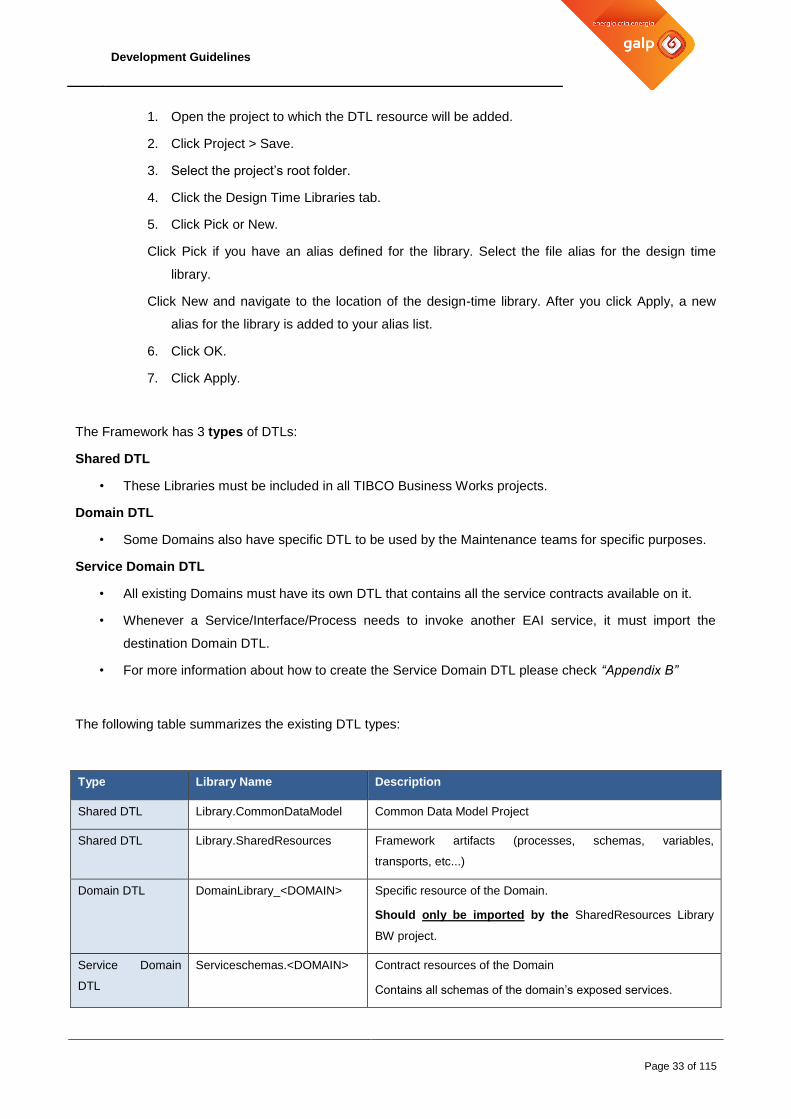
The following table summarizes the existing DTL types:
Type Library Name Description
Shared DTL Library.CommonDataModel Common Data Model Project
Shared DTL Library.SharedResources Framework artifacts (processes, schemas, variables,
transports, etc...)
Domain DTL DomainLibrary_<DOMAIN> Specific resource of the Domain.
Should only be imported by the SharedResources Library
BW project.
Service Domain
DTL
Serviceschemas.<DOMAIN> Contract resources of the Domain
Contains all schemas of the domain’s exposed services.

Development Guidelines
Page 34 of 115
Table 9 – Design Time Libraries
The next table details for each designer Repository project, which DTLs are imported and which ones they
export.
Repo Description Imported DTLs Exported DTLs
Library.CommonDataModel Contains all CDM
Schemas
- CommonDataModel
Library.Sharedresources Contains all
SharedResources artifacts
DomainLibrary_EAI SharedResources
repo2.EAI EAI Project that contains
the AEschema of the
Framework Log Adapters
CommonDataModel
SharedResources
DomainLibrary_EAI
repo2.<DOMAIN> All BW domains CommonDataModel
SharedResources
Serviceschemas.<TARGET
DOMAINS>
Serviceschemas.<DOMAIN>
Table 10 – Repositories and DTLs
3.7 Source Control
At the present date, the source control for TIBCO projects will be TFS.
The main repository is called APP TIBCO CONS. This is where GALP maintains the current developments
updated.
For each project there will be a Brach of the main repository with the name and code of the project. Each
branch will only contain the necessary resources needed for that specific project
When the development is stabilized, the source code is merged into the main branch and labelled with the
release number and release notes.

Development Guidelines
Page 35 of 115
Figure 15 – TFS Repository View

Development Guidelines
Page 36 of 115
4 Implementation Guidelines
All development naming should always be in English (UK) at all times (tasks, processes, channels, etc).
The exception is the Service Name that has to be in Portuguese
When needed, the developer should use labels to better document the processes definitions.
4.1 Naming conventions
DEV 7 - Naming conventions
This section describes the main naming conventions for:
- Services
- Interfaces
- Processes
- Messaging
- Variables
Other specific conventions must always be validated with GALP. This means that when new concepts/components are created due to the project evolution, their naming convention should be defined by GALP. The developing team is encouraged to propose new conventions when it detects that common concepts/components are depicted in various ways.
4.1.1 Services
All service names must follow the following rules:
Service name must be in Portuguese.
Operation (action) should follow the nomenclature language of existing services.
Underscores and dashes must be avoided (except underscores in Service Resources)
With the exception of period, no other punctuation characters are allowed.
The service name must be in upper camel case (ex: Carga, Fornecedor)
The operation name must be in lower camel case (ex: upsert, publish, get)
The Service and operation pair should be descriptive of the functionality that it implements. (e.g.:
Carga.pedido). If the chosen name respects all naming convention rules, then it doesn’t need an explicit
approval by GALP. Nevertheless, if necessary, GALP reserves the right to suggest name adjustments,
for instance during code review activities.

Development Guidelines
Page 37 of 115
4.1.2 Interfaces
All interface names must follow the following rules:
Underscores and dashes must be avoided (except underscores in Interface Resources)
With the exception of period, no other punctuation characters are allowed.
The interface name must be in upper camel case (ex: BpmINVOIC02, BpmSendVendor)
The operation name must be in lower camel case (ex: publish, receive)
Numbers are allowed
The Interface and operation pair name should be tied to the API functionality it connects to, allowing an
easy understanding of what it does. (ex. BpmINVOIC02.publish, BpmSendVendor.receive)
4.1.3 Processes
All process (e.g. LogSubscriber) names must follow the following rules:
Underscores and dashes must be avoided (except underscores in Processes Resources)
With the exception of period, no other punctuation characters are allowed.
The process name must be in upper camel case (ex: Gateway, LogSubscriber)
The operation name should be in lower camel case (ex: execute, get), however it can have some
exceptions (e.g.: ADB, ADSBL)
The process and operation pair name should be tied to the API functionality it exposes allowing an easy
understanding of what it does. (ex. LogSubscriber.ADB, HTTP2JMS.process)
All subprocess names must follow the following rules:
Names and folders should not have any prefix and must use a camel case nomenclature.
4.1.4 Messaging
Please refer to section 4.4 Service Schemas and section 0
Development Guidelines
Page 38 of 115
JMS Messaging, for a complete Messaging description; this includes the approved patterns and naming
conventions.
4.1.5 Variables
All Global Variables names must be upper camel case.
E.g. (variable name): BusinessDomain/EAI/Processes/HTTP2JMS/execute/URL
4.2 Variable Usage
4.2.1 Global Variables
DEV 8- Global Variables
All environment and connection related configuration should be defined as a global variable, with the exception of queue names(). Global variables must have a comment explaining its purpose and values. Global variables for passwords must use the “Password” type in order to be obfuscated automatically.
All Global Variables names must be upper camel case.
If there is the need to use obfuscated passwords in process activities, there is two workarounds:
1. Use custom functions that perform the plain text cypher and decipher. These functions will be provided by the Service Framework team, on “as needed” basis.
2. Use the following code inside a Java Code activity in your BW process:
import com.tibco.pe.plugin.PluginProperties;
out_var_1=PluginProperties.getProperty("tibco.clientVar.pass");
The Global Variables structure should be as follows:
Default BW variables:
o Contain the typical BW variables: ADBScriptFileDir, DirLedger, DirTrace, HawkEnabled…
o No variables should be added here.
Business Domain variables:
o Structure that will contain all business domain variables including its services, interfaces and
processes.
o All variables for the respective project should be added here while following the same
structure of the business works folders. An example can be seen bellow:
Development Guidelines
Page 39 of 115
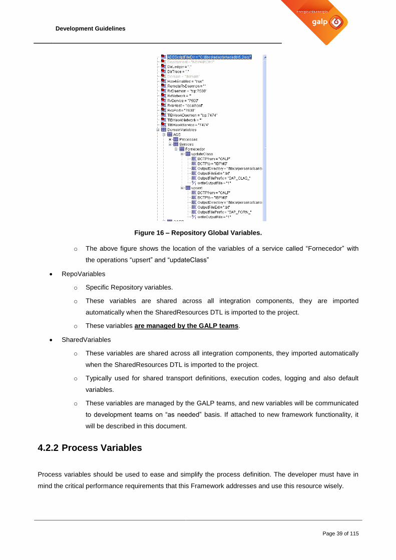
Figure 16 – Repository Global Variables.
o The above figure shows the location of the variables of a service called “Fornecedor” with
the operations “upsert” and “updateClass”
RepoVariables
o Specific Repository variables.
o These variables are shared across all integration components, they are imported
automatically when the SharedResources DTL is imported to the project.
o These variables are managed by the GALP teams.
SharedVariables
o These variables are shared across all integration components, they imported automatically
when the SharedResources DTL is imported to the project.
o Typically used for shared transport definitions, execution codes, logging and also default
variables.
o These variables are managed by the GALP teams, and new variables will be communicated
to development teams on “as needed” basis. If attached to new framework functionality, it
will be described in this document.
4.2.2 Process Variables
Process variables should be used to ease and simplify the process definition. The developer must have in
mind the critical performance requirements that this Framework addresses and use this resource wisely.
Development Guidelines
Page 40 of 115
For example, recurrent xpath queries used along the process definition should be set to a process variable in
order to optimize its processing.
The camel case naming convention also applies.
4.2.3 Shared Variables
SharedVariables are typically defined in the SharedResources DTL, to date the defined shared variables
allow storing current service context information, service business keys, error handling data and execution
code translation information as well as running services information.
These variables can also be used to store real time information that can be updated seamlessly across
integration components via a broadcast protocol like Rendezvous
4.2.4 Updating Variables in real time
Variables that hold runtime configuration for the services (e.g. errors, routing rules, etc.) can be updated in
two ways:
1. By sending any Rendezvous message (empty or not) to the following subject:
GALP.<DOMAIN>.RV.CLEANENGINEVARS.SUB
When an Business Works engine receives this message it will:
Reset the engine routing configuration
Reset the engine Error translation configuration
Reset the Service catalog configuration
What is reset depends on the <DOMAIN> tag value and on what is on the message is sent.
a) If the message sent is empty or without a valid service, it will clean all information for all services of
that domain.
b) If the message sent contains a <service>.<action> only the BW engines that contain that
service.action will be reset. All the others will be ignored.
Note: The Domain is set on each Business Works engine on the “RepoVariables/Name” Global variable, so it
must be set specifically on each BW deployment.
DEV 9- Message Format for cleaning Variables
The message format that is expected is a normal one that can be send with the “tibrvsend” command that comes with every Rendezvous installation

Development Guidelines
Page 41 of 115
DATA = <service>.<action>
Example:
To reset all service information in memory of all engines with the ERP domain.
> tibrvsend “GALP.ERP.RV.CLEANENGINEVARS.SUB” “all”
To reset the information of the service CORP.Documento.upsert
> tibrvsend “GALP.CORP.RV.CLEANENGINEVARS.SUB” “Documento.upsert”
2. By using the “Synchronize” feature on EWU, Module Catalog/Services
This feature works by input the Domain that the user wants to synchronize and the logic previously described
will be executed for resetting the variables of an entire domain.
4.3 Integration Architecture
4.3.1 Service Design and Granularity
DEV 10 - Service Design
The designed services should fall in one of the following categories:
- Functional Domain Services
- Functional Domain Interfaces
- Corporative Enterprise Services
- SOA Framework Services
- Processes
Development Guidelines
Page 42 of 115
Domain
Functional Services
Functional Corporative
Orchestrated
Services
EAI
SOA Framework
Services
ProcessesFunctional Interfaces
Processes
Processes
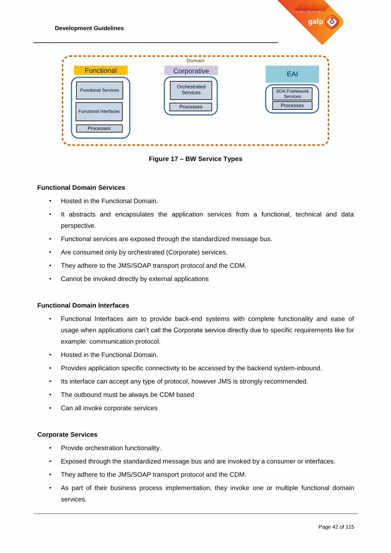
Figure 17 – BW Service Types
Functional Domain Services
• Hosted in the Functional Domain.
• It abstracts and encapsulates the application services from a functional, technical and data
perspective.
• Functional services are exposed through the standardized message bus.
• Are consumed only by orchestrated (Corporate) services.
• They adhere to the JMS/SOAP transport protocol and the CDM.
• Cannot be invoked directly by external applications
Functional Domain Interfaces
• Functional Interfaces aim to provide back-end systems with complete functionality and ease of
usage when applications can’t call the Corporate service directly due to specific requirements like for
example: communication protocol.
• Hosted in the Functional Domain.
• Provides application specific connectivity to be accessed by the backend system-inbound.
• Its interface can accept any type of protocol, however JMS is strongly recommended.
• The outbound must be always be CDM based
• Can all invoke corporate services
Corporate Services
• Provide orchestration functionality.
• Exposed through the standardized message bus and are invoked by a consumer or interfaces.
• They adhere to the JMS/SOAP transport protocol and the CDM.
• As part of their business process implementation, they invoke one or multiple functional domain
services.
Development Guidelines
Page 43 of 115
• Cannot connect to back-end systems directly
• May also invoke other orchestrated services.
SOA Framework Services/Processes
• Exists as a service, process or as an internal SharedResources Process.
• Provide generic functionality used in the implementation of other services.
• Can be invoked by any Service, Interface or on an as-needed basis. (Example: Sequencing Service,
Backup Service)
• Exposed inline or through the standardized message bus and adhere to the JMS transport protocol.
• Does not need to follow the CDM
• Creation and Usage of this services must have explicit authorization by the Architecture team
Domain Processes
• Resources that do not comply with the normal service standards.
• E.g.: Gateways, Dispatchers, Workers, etc…
The design must always be validated by the architecture team.
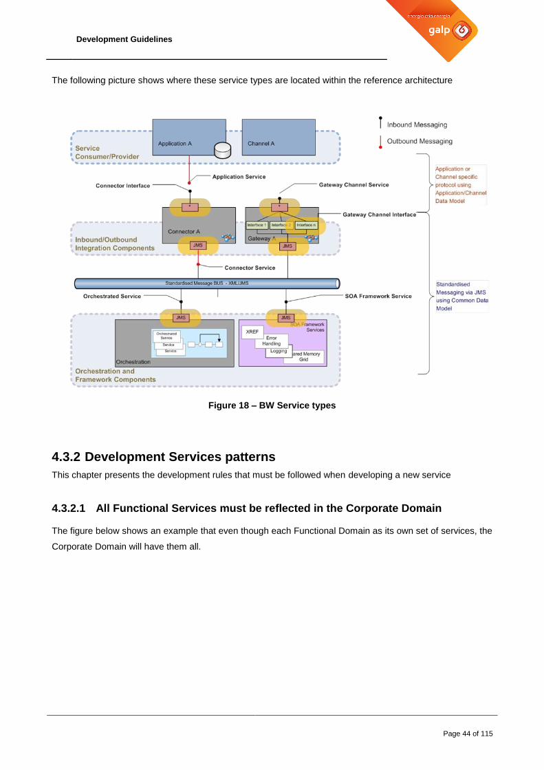
Development Guidelines
Page 44 of 115
The following picture shows where these service types are located within the reference architecture
Figure 18 – BW Service types
4.3.2 Development Services patterns
This chapter presents the development rules that must be followed when developing a new service
4.3.2.1 All Functional Services must be reflected in the Corporate Domain
The figure below shows an example that even though each Functional Domain as its own set of services, the
Corporate Domain will have them all.

Development Guidelines
Page 45 of 115
CRM Domain
Service A
SIEBEL
SIEGE
SILUB
ERP Domain
Service D
SAP
LUBCEL
SIC
CORP Domain
Service A
Service B
Service C
Service E
Service B
Service C
Service D
Service E
Figure 19 – Service Deployment location
In these scenarios, the service on the corporate Level and on the Functional level should have the same
name and actions.
4.3.2.2 Data split across systems
The next picture presents a scenario that, due to the enterprise existing layout, the data is split across
different services in different domains. In this scenario only a single corporate service is needed that will in
turn connect to the existing functional ones.
CRM Domain
Customer.get
SIEBEL
SIEGE
SILUB
ERP Domain
Customer.get
SAP
LUBCEL
SIC
CORP Domain
Customer.get
Figure 20 – Service Deployment location across split back-end applications

Development Guidelines
Page 46 of 115
Like in the previous scenario, the service on the corporate Level and the services on the Functional levels
should have the same names and actions.
4.3.2.3 Example: Service that is the result of two other Services
When an orchestration service is needed, a corporate service should only call other corporate services
directly. By following the previous 2 (two) scenarios, the invoked corporate services will then invoke their
respective Functional services that could be called directly as well
CRM Domain
Customer.get
SIEBEL
SIEGE
SILUB
CORP Domain
Customer.getAccountsAccount.get
Customer.get
Account.get
Figure 21 – Orchestration development
The above picture presents an orchestrated corporate service that invokes other corporate services instead
of calling the functional services directly. This approach will maximize service reutilization by allowing the
“sub-services” to be called externally as well.
4.3.3 Standardized Message Bus
The standardized message bus provides interoperability and transport between services. It uses the JMS
standard as an interface to the messaging server. The messages need to conform to a well-defined, GALP
specific integration object model.
DEV 11- Standardized Message Bus
The standardized message bus provides a JMS messaging infrastructure which is implemented using TIBCO EMS. Services communicate using SOAP/EMS. Message data should be formatted according to the CDM.

Development Guidelines
Page 47 of 115
The following picture focus on the message bus, and the BW service types attached to it.
Figure 22 – Standardized Message Bus
It allows the standardization of the application or channel specific protocol based on the application’s or
channel’s data model to the normalized messaging infrastructure using the Common Data Model. This
facilitates the service interoperability and minimizes the transformations between service invocations in the
various integrations components thus promoting the platform performance.
4.3.4 Common Object Model (COM)
DEV 11- Standardized Message Bus
A COM object and its attributes cannot be created or used by a service with approval by the Architecture team.
A COM (Common Object Model) is a single object composed by an element and its xsd:attributeGroup.
Each attribute might contain restrictions on their use.
These objects will be used to define a service schema. All Data Integration Exchanges must be made
throughout COM elements and its attributes
At design time, the COM must be created on the “Library.CommonDataModel” repository under the
“/SharedResources/SchemaDefinitions/COM” directory.
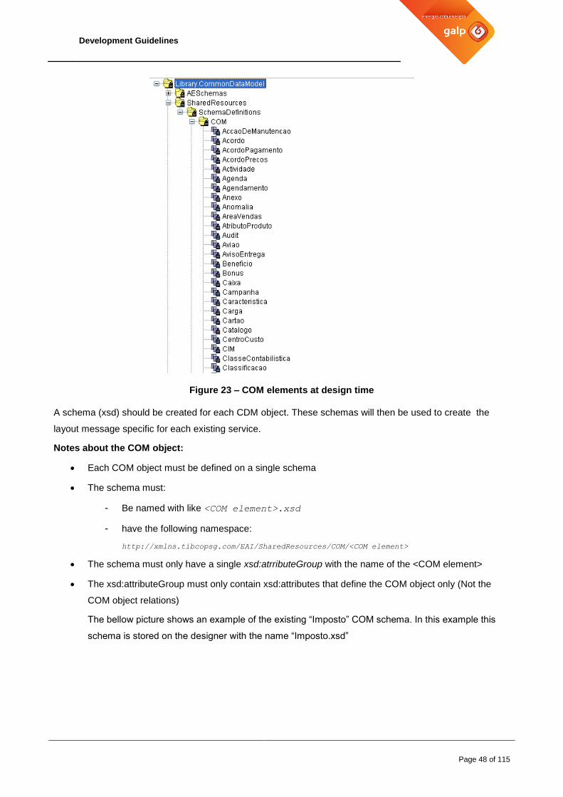
Development Guidelines
Page 48 of 115
Figure 23 – COM elements at design time
A schema (xsd) should be created for each CDM object. These schemas will then be used to create the
layout message specific for each existing service.
Notes about the COM object:
Each COM object must be defined on a single schema
The schema must:
- Be named with like <COM element>.xsd
- have the following namespace:
http://xmlns.tibcopsg.com/EAI/SharedResources/COM/<COM element>
The schema must only have a single xsd:atrributeGroup with the name of the <COM element>
The xsd:attributeGroup must only contain xsd:attributes that define the COM object only (Not the
COM object relations)
The bellow picture shows an example of the existing “Imposto” COM schema. In this example this
schema is stored on the designer with the name “Imposto.xsd”

Development Guidelines
Page 49 of 115
Figure 24 – Example of COM element “Imposto”
4.3.5 Service Data Definition (SDD)
DEV 12-Service Data Definition
Starting from April 2014, all new services must use a SDD schema
The Service Data Definition is a XML schema that defines the service element relations between each other
on a specific service context.
While a COM schema only defines the attributes of a single object, the SDD defines the relations between
each COM objects.
For a SDD to be valid it must follow these rules:
- All elements must be optional and repeatable (0 to many)
- An element must always be related to an existing COM element. This means that :
o an element must always reference an attributeGroup
o an element must have the same name has the attributeGroup it refers to
- the root element must be called “Body”
- the schema must have the following namespace:
http://xmlns.tibcopsg.com/SharedResources/SchemaDefinitions/Services/<service name>
Figure 25 – Graphical example of the SDD of the service “Documento”
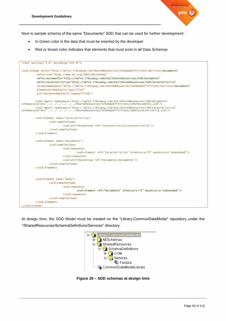
Development Guidelines
Page 50 of 115
Next is sample schema of the same “Documento” SDD that can be used for further development:
In Green color is the data that must be inserted by the developer
Red or brown color indicates that elements that must exist in all Data Schemas
<?xml version="1.0" encoding="UTF-8"?>
<xsd:schema xmlns="http://xmlns.tibcopsg.com/SharedResources/SchemaDefinitions/Services/Documento"
xmlns:xsd="http://www.w3.org/2001/XMLSchema"
xmlns:Documento="http://xmlns.tibcopsg.com/EAI/SharedResources/COM/Documento"
xmlns:Caracteristica="http://xmlns.tibcopsg.com/EAI/SharedResources/COM/Caracteristica"
targetNamespace="http://xmlns.tibcopsg.com/SharedResources/SchemaDefinitions/Services/Documento"
elementFormDefault="qualified"
attributeFormDefault="unqualified">
<xsd:import namespace="http://xmlns.tibcopsg.com/EAI/SharedResources/COM/Documento" schemaLocation="../../../../../../SharedResources/SchemaDefinitions/COM/Documento.xsd"/>
<xsd:import namespace="http://xmlns.tibcopsg.com/EAI/SharedResources/COM/Caracteristica" schemaLocation="../../../../../../SharedResources/SchemaDefinitions/COM/Caracteristica.xsd"/>
<xsd:element name="Caracteristica">
<xsd:complexType>
<xsd:attributeGroup ref="Caracteristica:Caracteristica"/>
</xsd:complexType>
</xsd:element>
<xsd:element name="Documento">
<xsd:complexType>
<xsd:sequence>
<xsd:element ref="Caracteristica" minOccurs="0" maxOccurs="unbounded"/>
</xsd:sequence>
<xsd:attributeGroup ref="Documento:Documento"/>
</xsd:complexType>
</xsd:element>
<xsd:element name="Body">
<xsd:complexType>
<xsd:sequence>
<xsd:element ref="Documento" minOccurs="0" maxOccurs="unbounded"/>
</xsd:sequence>
</xsd:complexType>
</xsd:element>
</xsd:schema>
At design time, the SDD Model must be created on the “Library.CommonDataModel” repository under the
“/SharedResources/SchemaDefinitions/Services” directory.
Figure 26 – SDD schemas at design time

Development Guidelines
Page 51 of 115
4.3.6 Execution Codes
Whenever a service (or interface) is executed, either synchronous or asynchronous, an execution code will
be generated at the end of the operation containing the result code of the operation made.
This Code will be sent back to the Client system that invoked it in synchronous services and published to the
log Database whenever at least the INFO role is enabled.
DEV 13- Execution Codes
In order to normalize the Execution Codes (aka Error Codes), all EAI services must follow the following nomenclature:
<DOMAIN | COM | SRV >-<Execution Code>
Where:
DOMAIN corresponds to the Functional Domain where the service or Interface is.
COM corresponds to a categorization of a common code that is generic throughout the Service
Framework. COM errors can be thrown at domain or service level.
SRV for specific service execution codes.
Execution Code for the status/error that was raised.
This normalization will allow a better reusability of Exception Handling Rules and an easy comprehension of
the service status from all involved teams.
4.3.6.1 Common Codes
Below is a list of the common codes that should be used in all services and interfaces whenever it justifies
and it is possible:
Execution Code Code Meaning Description
COM-000 Success The process was executed with Success.
COM-001 Failed The process failed its execution.
Usually (but not limited to) used on Boolean type return
services.
An example can be a “validate Login service” which can
only be Success (login is OK) or failed (login is wrong)
COM-002 Partial Success The process failed its execution but still has performed
some work.
COM-003 Message Filtered Used when the response message was filtered.
COM-004 Service Not Initialized Used when the process fails its initialization.

Development Guidelines
Page 52 of 115
Execution Code Code Meaning Description
COM-005 Service Disabled When a service is configured as disabled.
COM-100 Not Found Used when a service must retrieve, update or delete
something and the criteria it was used wasn’t satisfied to do
it.
This code should be used generically.
Example:
o Update a record that doesn’t exist o Trying to get information of an entity with an
inexistent code o Poll for a file in a directory but the file isn’t there o Etc
COM-101 No Destination Used when no routing destination is found.
COM-103 Received Error Used when an unexpected error is received
COM-105 Empty Message Used when an empty message is detected.
COM-106 Invalid Parameters Field doesn’t have the correct format. (trying to put a text in
a number field for instance)
COM-400 Error Treated Manually treated error
COM-500 Timeout Used whenever the process tries to connect to some
component and the maximum time to wait for the
connection (or data) is reached.
COM-501 HTTP
Communication Error
An HTTP communication error occurred.
COM-503 Transport Error Connection to target system fails (connecting to JMS server,
to a target system, etc)
COM-504 Channel Closed Error Used when a channel transport error occurs.
COM-505 Closure Achieved Used when unhandled service closure is necessary
COM-997 Functional Error Target system returned an error that is listed on the
functional errors for this service
COM-998 Unknown Error in
Target System
The called Target system returned an unknown error back
to the service.
COM-999 Unknown Error Unexpected error occurred inside the component that holds
the service
Table 11 – Common Execution Codes
This list is not static and it is expected that more common codes may exist as projects evolve.
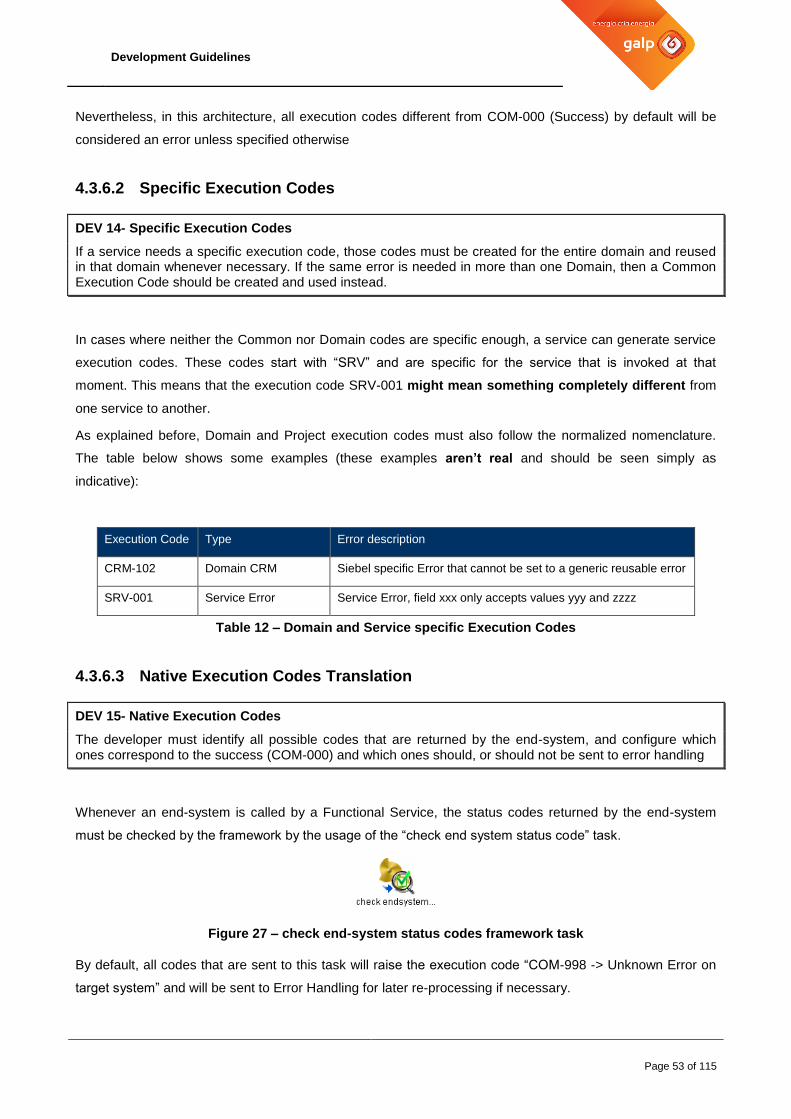
Development Guidelines
Page 53 of 115
Nevertheless, in this architecture, all execution codes different from COM-000 (Success) by default will be
considered an error unless specified otherwise
4.3.6.2 Specific Execution Codes
DEV 14- Specific Execution Codes
If a service needs a specific execution code, those codes must be created for the entire domain and reused in that domain whenever necessary. If the same error is needed in more than one Domain, then a Common Execution Code should be created and used instead.
In cases where neither the Common nor Domain codes are specific enough, a service can generate service
execution codes. These codes start with “SRV” and are specific for the service that is invoked at that
moment. This means that the execution code SRV-001 might mean something completely different from
one service to another.
As explained before, Domain and Project execution codes must also follow the normalized nomenclature.
The table below shows some examples (these examples aren’t real and should be seen simply as
indicative):
Execution Code Type Error description
CRM-102 Domain CRM Siebel specific Error that cannot be set to a generic reusable error
SRV-001 Service Error Service Error, field xxx only accepts values yyy and zzzz
Table 12 – Domain and Service specific Execution Codes
4.3.6.3 Native Execution Codes Translation
DEV 15- Native Execution Codes
The developer must identify all possible codes that are returned by the end-system, and configure which ones correspond to the success (COM-000) and which ones should, or should not be sent to error handling
Whenever an end-system is called by a Functional Service, the status codes returned by the end-system
must be checked by the framework by the usage of the “check end system status code” task.
Figure 27 – check end-system status codes framework task
By default, all codes that are sent to this task will raise the execution code “COM-998 -> Unknown Error on
target system” and will be sent to Error Handling for later re-processing if necessary.

Development Guidelines
Page 54 of 115
During the development the document “PIGENT15 – Error Codes” must be filled with the codes that can be
identified and correspond to existing Common Execution Codes (which codes correspond to Success, Invalid
Parameters, to Transport Errors , etc)
The next table presents an example of how the document should be used:
Native Code Common
Code
Error description
(Message that will be
returned)
Is it an error?
Should be sent to
Error Handling?
SBL-035 COM-100 No data found No No
0 COM-000 Success No No
12 COM-106 Invalid Parameters Yes No
15 COM-500 Timeout Yes Yes
Table 13 – Native Execution Codes translation
This configuration has to be registered in the Framework database model, more specifically in the table
T_EAI_ERROR_SERVICE. This can be done through SQL Insert statements on the database or through the
EWU error configuration module.
The task “check end system status code” then uses this configuration to translate all native codes and also to
set the IsError and HasHandling properties. These properties will define if this event should be considered an
error and if it should be sent to the Error Handling process, for automatic or manual treatment and
reprocessing. These properties work independently from each other, which means that not all errors have to
be sent to EH.
Nonetheless, there are some default behaviors that have to be taken into account:
All services (Corporate and Functional) should have an error configuration, detailing all possible
errors and how they should be treated. This configuration will be taken into account when
determining the error handling behavior.
In the absence of a configuration, a check on the native error is made:
o If the native error code is already a canonical code (ex: COM-101), the default canonical
error catalog is checked to determine the error handling behavior for this scenario.
o If the native error code is not a canonical code but is returned from an endSystem, the event
is marked as a generic Target System Error (COM-998), with both isError and hasHandling
flags active.
o If the native error code is not a canonical code and is not returned from an endSystem, the
event is marked as an Unknown Error (COM-999), with both isError and hasHandling flags
active.

Development Guidelines
Page 55 of 115
4.4 Service Schemas
4.4.1 Overview
Messaging pattern
SOAP over JMS is the adopted messaging protocol for the integration components. All inter component
communication is done using this protocol.
Externally to the components, the messaging pattern should respect the guidelines provided in chapter 4.3.3
Standardized Message Bus
Message description
Services use EMS as the messaging infrastructure. Service messages always follow the same structure.
They are composed by shared library XSDs: Header schemas that define the HeaderInput/HeaderOutput. In
turn, In/Out objects are defined at the service level and these objects make use of the CommonDataModel
Library.

Development Guidelines
Page 56 of 115
Figure 28 – Header Schema

Development Guidelines
Page 57 of 115
Figure 29 – Message Data Schema
All necessary schemas (EAI and CDM) are provided by the SharedResources DTL. These schemas are
open to evolution and all necessary changes must be submitted to GALP approval. This means that the
development team can identify and propose changes to these schemas to accommodate new projects and
requirements. These changes will then be evaluated by the Service Framework and implemented if
necessary.
Figure 30 – SharedResources DTL
These schemas are mandatory, and provide key elements that should always be used, such as Control and
Status complex types.

Integration Development Guidelines
Page 58 of 115
HeaderInput/HeaderOutput
Main Element Element Description Mandatory
Header trackingID Unique internal identifier that identifies
the entire transaction/request internally
between all GALP applications.
Yes whenever possible
If not used a GUID identifier will be
generated internally for each request
and returned in the service response.
correlationTrackingID Whenever a message needs to send
back information of the previous
trackingID that originated this new
message.
Should only be used for synchronous
patterns over asynchronous invocations
No
parentLogID Attribute used to cross reference the
logID of the step/service that generated
the current execution. It will allow to
create a graphic with the chain of
execution of a given transaction/request
Yes, for services using the latest
framework version
sequenceID Used to identify the last point in the
service where the service halted In
case of an error.
When the message is resubmitted with
this field, the service should advance to
the right point automatically
No
step Identifies the last history step.
if this field is not received then the
current service must automatically
assume it is the first step and as such
put it to 1 (one)
If this field is sent, then the service
should increment the received value by
1 (add one).
Yes whenever possible
creationTime dateTime when the request was
created.
The first step should always set this
field to its own start dateTime.
If the field is already filled, then it should
not be changed. The received value
should be kept throughout all services
of the same transaction (same
iTrackingId)
Yes whenever possible
timeout When populated, indicates that the application that sent the message will only wait for a reply this amount of
No
If sent each service framework will

Integration Development Guidelines
Page 59 of 115
milliseconds.
The receiving service must take this value in account when making its own requests.
remove 2 seconds (t-2000) from it.
If empty then it will check for the
default Global Timeout Variable and
uses its time. Usually is set to 60
seconds (60000)
If the default Global value is empty or
does not exist, then the value will be
initialized at 60 seconds (60000)
errorID Unique ID created by the Error
handling.
A message sent with an errorID
indicates that it is being resubmitted by
the Error Handling. This will be used to
uniquely identify the error.
No
Should never be used in
development.
The Error-handling framework will use
it automatically when needed
handleError Boolean value.
When a value of “true” is sent to a
service indicates the target service
should not send anything to the error
Handling
This field is used when the previous
service (usually an Orchestration one)
is responsible to handle the errors and
as such there is no need for the target
domain services handle the errors
themselves.
No
If not defined, the framework will
assume it’s value is “false”
History owner Component name Repetitive element that contains
information of each service and
component that was invoked before.
It’s automatically filled by the
framework.
Should not be changed unless needed
for very specific scenarios
domain
type
serviceName
action
version Not used
timestamp Timestamp when this service was
called
component Type of component
transport JMS, JMSSOAP, HTTP, TCP
subject JMS queue, HTTP URL, etc
step Sequence of the history element
application Application name where the service
connects to
Credentials applicationID Application Identification for
authorization (security) reasons
No
These fields should be used when a

Integration Development Guidelines
Page 60 of 115
login Login to be used to connect to a target
application
target service needs, for each call, to
connect with different credentials.
password Password used to connect to a target
application
Configuration If needed, it will allow setting specific
JMS priorities and timeouts for a
specific service for each call.
No
Although is Developed, to use ask
Architecture team
eDetail eCodes eCode GALP Canonical success or execution
code according to the error tables seen
on this document
Yes on the reply
eDescription GALP Canonical description according
to the eCode sent.
No, but recommended
nCodes eCode Native Status code returned by the
target applications (if exists)
Yes whenever the target application
returns a status code
eDescription Native result description returned by the
target application
Yes whenever the target application
returns a status description
Filter destination Used for the invoker to identify specific
destinations.
Check Routing Rules chapter
No
Idioma
Should be used to identify the language
the invoker is expecting to receive on
this destination
No
uniqueDestinationFlag Boolean (true/false) to be used on
routing rules.
Check Routing Rules chapter
No
Fields Currently not used Currently not used
Routing Domain Name Target Domain that was discovered by
the Routing Rules
Check Routing Rules chapter
Usually is Automatically set by the
Framework
Application Target Application that was discovered
by the Routing Rules
Check Routing Rules chapter
Usually is Automatically set by the
Framework
Table 14 – HeaderInput and HeaderOutput description
Additionally, developers must configure the services, interfaces or processes schemas based on these
foundational schemas.

Integration Development Guidelines
Page 61 of 115
Figure 31 – Service Data Schema
These schemas must always reside inside the _ServiceResources/Schemas folder.
The WSDL that exposes that service schema must also exist on the _ServiceReources/WSDL folder
4.4.2 Developing the Service Schemas
The service input and outputs are set on the Data.xsd schema that must exist on each service under the
“_ServiceResources/SchemaDefinitions” folder
Next is sample schema that can be used for further development:
In Green color is the data that must be inserted by the developer
Red or brown color indicates that elements that must exist in all Data Schemas
<?xml version="1.0" encoding="UTF-8"?>
<xsd:schema xmlns="http://xmlns.tibcopsg.com/CORP/Services/Factura/Data"
xmlns:xsd="http://www.w3.org/2001/XMLSchema"
xmlns:ns1="http://xmlns.tibcopsg.com/EAI/SharedResources"
xmlns:Factura="http://xmlns.tibcopsg.com/SharedResources/SchemaDefinitions/Services/Factura”
targetNamespace="http://xmlns.tibcopsg.com/CORP/Services/Factura/Data"
elementFormDefault="qualified"
attributeFormDefault="unqualified">
<xsd:import namespace="http://xmlns.tibcopsg.com/EAI/SharedResources" schemaLocation="../../../../../../SharedResources/SchemaDefinitions/EAIMessaging/header.xsd"/>
<xsd:import namespace="http://xmlns.tibcopsg.com/SharedResources/SchemaDefinitions/Services/Factura" schemaLocation="../../../../../../SharedResources/SchemaDefinitions/COM/Services/Factura.xsd"/>
<!-- Only change DOMAIN NAME and SERVICE NAME parameters above -->
<!--
/******************************************************************************
Name: inputData for Factura
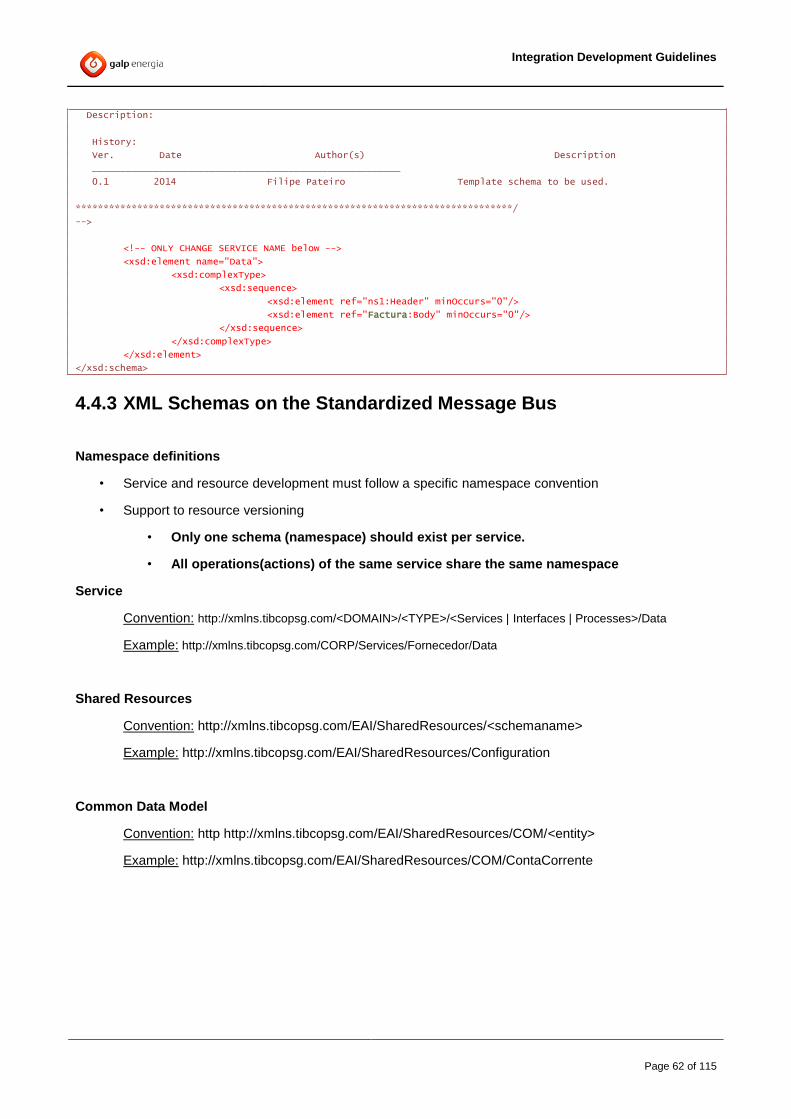
Integration Development Guidelines
Page 62 of 115
Description:
History:
Ver. Date Author(s) Description
_______________________________________________________
0.1 2014 Filipe Pateiro Template schema to be used.
******************************************************************************/
-->
<!-- ONLY CHANGE SERVICE NAME below -->
<xsd:element name="Data">
<xsd:complexType>
<xsd:sequence>
<xsd:element ref="ns1:Header" minOccurs="0"/>
<xsd:element ref="Factura:Body" minOccurs="0"/>
</xsd:sequence>
</xsd:complexType>
</xsd:element>
</xsd:schema>
4.4.3 XML Schemas on the Standardized Message Bus
Namespace definitions
• Service and resource development must follow a specific namespace convention
• Support to resource versioning
• Only one schema (namespace) should exist per service.
• All operations(actions) of the same service share the same namespace
Service
Convention: http://xmlns.tibcopsg.com/<DOMAIN>/<TYPE>/<Services | Interfaces | Processes>/Data
Example: http://xmlns.tibcopsg.com/CORP/Services/Fornecedor/Data
Shared Resources
Convention: http://xmlns.tibcopsg.com/EAI/SharedResources/<schemaname>
Example: http://xmlns.tibcopsg.com/EAI/SharedResources/Configuration
Common Data Model
Convention: http http://xmlns.tibcopsg.com/EAI/SharedResources/COM/<entity>
Example: http://xmlns.tibcopsg.com/EAI/SharedResources/COM/ContaCorrente

Integration Development Guidelines
Page 63 of 115
4.5 Java Code
4.5.1 BusinessWorks Java code activity
Custom code can be added to a process definition with the Java Code activity. This activity allows writing
standard Java code that can manipulate any of the process data or perform any chosen action.
The Java Code activity automatically creates an invoke() method in which the code is placed to be executed.
This method is called when the engine processes the Java Code activity.
The invoke() method will act as your main method. If needed additional methods can be created and called
from the invoke() method.
BW Java Code activities should only be used in scenarios where it doesn’t make sense to have an
externalized java project with custom classes. This means that only very simple classes, without any
business logic, will be accepted inside BW processes.
4.5.2 Third-party Libraries
When importing third-party libraries, it is necessary to validate with GALP the licensing terms, or if there is
any other similar library already licensed for the same purpose.
Third-party libraries must be placed in the TPCL folder inside <TIBCO_HOME>, and the necessary TRAs
(designer.tra and bwengine.tra) must be updated accordingly in the development Machines.
If necessary, on the various TIBCO environments, the prepandclasspath or appendclasspath engine
properties might also be used.
4.6 Connecting to Back-end Applications
When connecting to a back-end application (functional services, or functional interfaces) it is necessary to
evaluate with GALP in which domain the new connector service/interface will be placed. This evaluation can
be done mainly by analyzing back-end applications at a functional level.
The development team should suggest a domain to be used, based on the functional and technical analysis
of the integration. GALP reserves the right to complement this analysis and ultimately decide where to place
the service/process/interface.
4.6.1 Functional Services
For functional Services, it’s mandatory to make use of the provided framework resource
CheckEndSystemStatusCode, in order to categorize execution codes in a standard Header Status
structure.

Integration Development Guidelines
Page 64 of 115
The usage of this task will likely involve specific error configurations; as such the project must provide the
document “PIGENT015 – Service Error Configuration” that will configure the Service Framework
database, as described in the chapter 4.10.3 Service execution code translation
This chapter also describes the error resolution algorithm behind the CheckEndSystemStatusCode and its
underlying tables.
Each Functional service connects to one or more back-end applications, as such, the application name must
be configured on the Service Catalog (see chapter 4.10.1 Service Catalog) and sent to the Unified Log.
For more information on how to configure the application for each service invocation check chapter 4.6.3
Configuring the Application field.
4.6.2 Functional Interfaces
A functional Interface connects to a single source back-end application that application name must be
configured on the Service Catalog (see chapter 4.10.1 Service Catalog) and sent to the Unified Log.
For more information on how to configure the application for each service invocation check chapter 4.6.3
Configuring the Application field.
4.6.3 Configuring the Application field
The application is the back-end system name that uniquely identifies an existing GALP application. The
allowed application names can be seen later on this chapter.
The Development framework automatically inserts this value on the right DB fields based on the Catalog
information that each service must declare on the Catalog DB Table as explained on chapter 4.10.1 Service
Catalog.
The value inserted on the Catalog DB Table will be the default APPLICATION that will be sent to the Unified
log on every invocation, this is usually the right value for Interface and Functional Service Connectors.
The rules to set the application are the following:
1- All Interface connectors register the correct source back-end Application on the Catalog Table.
Although, it’s not recommended, If the same interface receives information from more than one
application, the “discoverSourceApplication” task should be used to identify it. This task
automatically sets the Application that will be sent to the Unified Log, overwriting the Catalog
Configuration
2- All Corporate services must be registered on the Catalog Table with “TIBCO” as the
APPLICATION.

Integration Development Guidelines
Page 65 of 115
If source applications call the Corporate services directly and if (and only on these cases) the
source application doesn’t log to the unified log, the “discoverSourceApplication” task should be
used to identify it. This task automatically sets the Application that will be sent to the Unified Log,
overwriting
3- The Functional Service connectors cannot (should not) change the APPLICATION on the code
directly.
The application information is set for each invocation with the following rules:
a) If an Incoming Message reaches the Functional Service and the field
Header/Routing/Domain/Application has a value, this will be the Application that will be
sent to the Unified Log.
b) If the above Header Field doesn’t have a value than the Default Value of the Catalog Table will
be used.
Basically, it’s the Corporate Service that invokes the Functional Service that says the Application the
functional service will connect to.
However, In order to set the Header field, the developer should not set the value directly on the
message Header itself. Instead it should use the Default value on the Catalog, or, if multiple
applications are connected to the same service, the user is highly recommended to use the
“routeEvent” task that returns all the domains and its target applications.
The return of this Framework task is the one that should be added to the Message.
On the other hand, if the developer uses the “route and forward” framework task, the header is
automatically created and no additional mapping is needed.
This means that the application that was set on the routing rules (see chapter 4.10.4 Routing Rules)
is the one that will be used. As such those applications should follow the same names as presented
on the next table:
Usually on Domain Application Name Usually on Domain Application Name
AQS IBPMS APP_SAPCORP SAPC
BI MKTA APP_SAPOIL SAPOIL
EC BDF APP_SAPRH SAPRH
EC IXOS APP_SAPISU SAPISU
EC EXHANGE APP_SAPCORP COCKPIT
EC GEDOC APP_SAPOIL COCKPIT
EC ARQUIVO APP_DCOUMENTUM DOCUMENTUM
CORP TIBCO APP_OPENSGC OPENSGC

Integration Development Guidelines
Page 66 of 115
ERP OPENSGC APP_PAG PAG
ERP SAP-PI APP_SOLUCAOMOVEL SOLUCAOMOVEL
ERP GESSICA APP_XRT LACAIXA
RETAIL SGRP APP_ARPU ARPU
RETAIL WMCARD GP2ARPU CCB
SAPPI SAPC APP_MAXIMO MAXIMO
SAPPI SAPP APP_OMP OMP
SAPPI SAPRH
SAPPI SAPISU
CRM SIEBEL
WEB GFO
WORKFLOW K2
COMPRAS EPCC
EAI MAXIMO
WORKFLOW OMP
Table 15 – Allowed Application configuration
The above tables describe the main applications that exist and are used on the Catalog, Routing and
be sent to Unified Logging. Others already exist and a detailed list can be found on EWU’s Catalog
module.
If a new application is needed than it needs explicit approval from GALP DSI Architecture team
beforehand.
4.7 Timeouts
The timeout parameter is mandatory to set in all tasks that accept it as a parameter like JDBC, JMS, HTTP,
etc. and must always be a value greater than 0 (zero).
The timeout value to use must not be set directly on the task, the value to use depends of the paradigm of
the endpoint.
4.7.1 Paradigm timeout rules
For synchronous services the rules are the following:
- The timeout value to use must be the one that comes in the incoming message on the
Header/timeout field and must be set in milliseconds
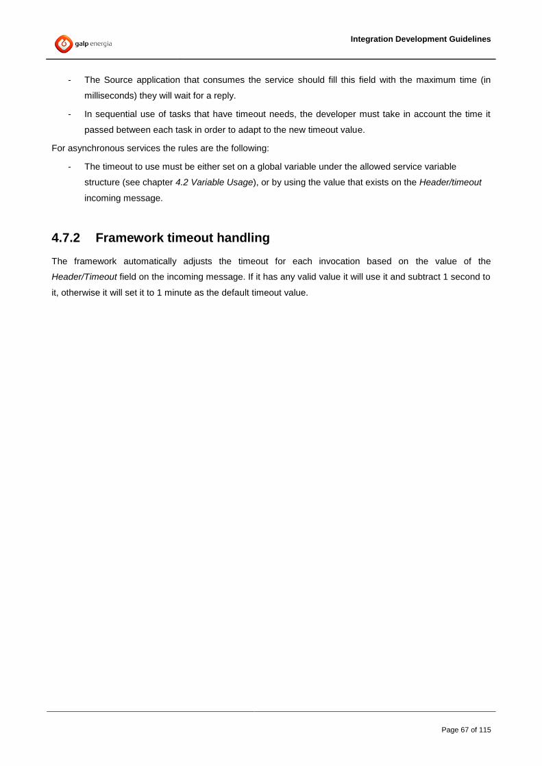
Integration Development Guidelines
Page 67 of 115
- The Source application that consumes the service should fill this field with the maximum time (in
milliseconds) they will wait for a reply.
- In sequential use of tasks that have timeout needs, the developer must take in account the time it
passed between each task in order to adapt to the new timeout value.
For asynchronous services the rules are the following:
- The timeout to use must be either set on a global variable under the allowed service variable
structure (see chapter 4.2 Variable Usage), or by using the value that exists on the Header/timeout
incoming message.
4.7.2 Framework timeout handling
The framework automatically adjusts the timeout for each invocation based on the value of the
Header/Timeout field on the incoming message. If it has any valid value it will use it and subtract 1 second to
it, otherwise it will set it to 1 minute as the default timeout value.
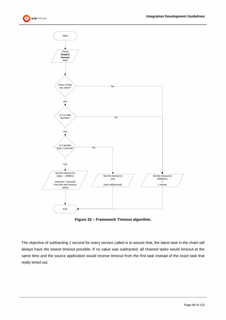
Integration Development Guidelines
Page 68 of 115
Start
End
Does it have
any value?
Is it a valid
Number?
yes
Yes
Set the timeout for
value - 2000ms
(remove 1 seconds
from the sent timeout
value)
No
No
Check
Header/
timeout
field
Set the timeout to
60000ms
=
1 minute
Is it greater
than 1 second?
Yes
Set the timeout to
1ms
(one millisecond)
No
Figure 32 – Framework Timeout algorithm.
The objective of subtracting 1 second for every service called is to assure that, the latest task in the chain will
always have the lowest timeout possible. If no value was subtracted, all chained tasks would timeout at the
same time and the source application would receive timeout from the first task instead of the exact task that
really timed out.

Integration Development Guidelines
Page 69 of 115
4.7.3 Framework timeout usage
For each synchronous service, the first task in the chain that needs to use a timeout should get the value by
using a “get Job Shared Variable” with the following configuration:
Figure 33 – Getting the Timeout value from the current Job Shared Variable
This Shared Variable will return the Header/timeout that was handled by the framework and that should be
used.
Take in account that for orchestrated services, the Header/timeout value to send to the next service must
have the corrected timeout value by subtracting the time spent on previous tasks.
4.8 Checkpoints
The Checkpoint activity performs a checkpoint in a running process instance. A checkpoint saves the current
process data and state so that it can be recovered at a later time in the event of a failure.
Due to performance requirements the usage of checkpoints should be avoided and only be used when
extremely necessary.
This means that it may only be used in cases where there is no other way to implement a specific technical
requirement. The latter option should always be discussed with the GALP Architecture team in order to
assess possible performance impacts on the respective processes.
4.9 Write to file system
Due to maintenance guidelines, no development can write to the file system. This means that the usage of
file tasks (including write to file, write to log or java methods to write lines to the file system) is strictly
prohibited.
The writing to the file system can only be used if there is a specific business need on the source system
and/or end system where TIBCO components connect to. (For example, the result of the service is to write a
file with data to be consumed by the end-system) in these cases, the location of the file to be written must be
previously discussed with GALP DSI and maintenance teams. The files should not be written on the TIBCO
file system if possible,
Otherwise, no logging or other middle process writing in files is allowed unless approved by GALP DSI
Architecture team.

Integration Development Guidelines
Page 70 of 115
4.9.1 House Keeping
If a business need or special permission is given to write on the file system, the service document must
contemplate the house keeping rules by setting:
- how many files will be written at any given time
- the maximum number of files allowed on the file system
- how long they should stay on the file system
- when they should be deleted / archived.
The service must make available all scripting and documentation that does the housekeeping.
4.10 Framework Configuration
This section focuses on the configurable tables that are used within the Framework.
4.10.1 Service Catalog
The service catalog is set on the TIBCAT.T_EAI_CATALOG table and contains all the existing services and
its configurations. A configuration must be specific up to operation version.

Integration Development Guidelines
Page 71 of 115
The following table depicts a possible data configured for the Service Catalogue:
EAI_CATALOG_ID 25 124
SYSTEM_FUNCTION_DOMAIN CORP ERP
SYSTEM_FUNCTION:_TYPE Services Services
SYSTEM_FUNCTION: Fornecedor Factura
SYSTEM_FUNCTION:_OPERATION generate validate
SYSTEM_FUNCTION_VERSION 1.0 1.0
CATALOG_STATUS FW V2 Auto Insert LogInsert
CATALOG_TIMESTAMP 2013-10-10 2014-11-11
SYSTEM_FUNCTION_PROFILE NORMAL DEBUG
ACT|VE_FLAG Y N
OLD_DBROLE INFO DEBUG
OLD_FILEROLE
SYSTEM_NAME TIBCO TIBCO
SYSTEM_NAME_CONNECTED TIBCO OPENSGC
CATALOG_SLA 500 500
HAS_EVENT N Y
BAM_PREFIX Factura
CATALOG_ERROR_100 0 0
CATALOG_ARQ_STATUS 1 1
Table 16 – T_EAI_CATALOG configuration
SYSTEM_FUNCTION_DOMAIN, SYSTEM_FUNCTION_TYPE, SYSTEM_FUNCTION,
SYSTEM_FUNCTION_OPERATION and SYSTEM_FUNCTION_VERSION fields uniquely identify a
service/interface/process.
The STATUS indicates how this service was inserted on the catalog. The valid values are:
FW V2 Auto Insert > Indicates that the service was inserted in real time by the Framework V2
LogInsert > Indicates that the service was inserted in real time by the Framework V1
The CATALOG_TIMESTAMP indicates the date when the service configuration was inserted on the catalog

Integration Development Guidelines
Page 72 of 115
For OLD_DBROLE and OLD_FILEROLE.
The supported values for these properties are:
INFO – Only logs to the EAI_LOG_HEADER and EAI_LOG_KEYS in case of success and to
EAI_LOG_DEBUG in case of Error
DEBUG – Always logs to all tables. Should not be used in Production
null – does not log any information.
For a quick reference, the following are a brief description of the Unified logging tables.
EAI_LOG_HEADER - Contains the main logging information, such as tracking ids, timestamps, execution codes and
messages as well as the duration for each of the executed steps. For each service call, this table will contain one entry
per integration component it passed through.
EAI_LOG_KEY - Contains the business keys for each of the executions.
EAI_LOG_DEBUG - Contains the inbound and outbound message payload for each of the executions.
The SYSTEM_NAME column holds the unique identifier of the system that implements the service. For
services developed in the Framework the value should be TIBCO.
The SYSTEM_NAME_CONNECTED column holds the unique identifier of the system that the service
connects to. For example, a service developed on CRM domain usually the APPLICATION is “SIEBEL”
The SYSTEM_NAME and SYSTEM_NAME_CONNECTED pair will allow to identify, in case of an error, if
the responsibility of the errors belongs to a wrongly implemented service or to a failure on the application
where the service connects to.
The CATALOG_SLA column should hold the maximum execution time in which service must finish, in
milliseconds. If a service takes more than this time to finish, the flag OUT_SLA on the EAI_LOG_HEADER
table will be set to “1”
The HAS_EVENT column is a flag {Y;N} that indicates if the service generates an event when it is executed.
Generate an event means that a message will be sent to the BAM framework. For more information please
check the BAM architecture Document
The BAM_PREFIX column is used by the BAM framework and it’s only used when the EVENT is set to “Y”
For more information please check the BAM architecture Document

Integration Development Guidelines
Page 73 of 115
The CATALOG_ERROR_100 column is a special column for statistical analysis and to be used only by the
Architecture team. Whenever is set (value=1) the errors on this service will be ignored by the statistical
algorithms.
The CATALOG_ARQ_STATUS column indicates if the service was approved by the Architecture (value=1)
or not (value=0). This value should never be set by anyone. It’s the responsibility of the Architecture team to
change the value whenever necessary.
4.10.2 Canonical Execution Codes
The TIBCAT.T_EAI_ERROR_CATALOG table contains the entire canonical error catalogue for the SOA
Framework. It is composed by two columns, in which we define:
- The status code (SATUS_CODE) for the framework execution codes
- A flag (IS_ERROR) with the values {N;Y} that defines if the code should send to error
handling and raise an error or not
- A field (SYSTEM_RESPONSIBLE) that indicates, in case of an error (IS_ERROR=Y) if the
responsibility of the error is it of the System that holds the Service (value=”S”) or it of the
Application that service connects to (value=”A”)
The following table depicts the possible data configured for the Error Catalogue:
STATUS_CODE IS_ERROR SYSTEM_RESPONSIBLE
COM-000 N A
COM-001 N A
COM-002 N A
COM-003 N A
COM-004 N A
COM-100 Y A
COM-101 Y S
COM-102 Y A
COM-104 Y A
COM-105 Y A
COM-106 Y A

Integration Development Guidelines
Page 74 of 115
COM-400 N S
COM-500 Y A
COM-501 Y A
COM-502 Y A
COM-997 Y A
COM-998 Y A
COM-999 Y S
Table 17 – T_EAI_ERROR_CATALOG configuration
4.10.3 Service execution code translation
The TIBCAT.T_EAI_ERROR_SERVICE table contains the error configurations for each Service.
A Service represents a unit capable of some sort of processing (e.g. a TIBCO Service, a Channel Manager
Interface, etc…). The goal of this table is to allow the categorization of errors by the following hierarchy:
Domain
Type
Service / Interface / Process
Operation
Allows mapping a specific native code (SYSTEM_FUNCTION_NATIVE_CODE) that occurred on a service,
to a Canonical execution code (STATUS_CODE) while inform if it is an error with the IS_ERROR flag and if
it should be sent to the Error Handling mechanism with the HAS_HANDLING flag.
Also, for each Native Code, it allows to identify who is responsible for that error (SYSTEM_RESPONSIBLE):
o Is it on the Application (Value=A) that returned the error (eg: Timeout while waiting for
response)
o Is it on the System (Value=S) that holds the service (eg: Wrong mappings)
The Table should be read the following way:
When The Service XYZ (identified by DOMAIN,TYPE,SERVICE,OPERATION)
Returns a status Code ABC (set on the SYSTEM_FUNCTION_NATIVE_CODE)
The framework should see this as a canonical error COM-XXX (set on STATUS_CODE)
And it should (value=Y) or not (value=N) be an error (set on IS_ERROR)
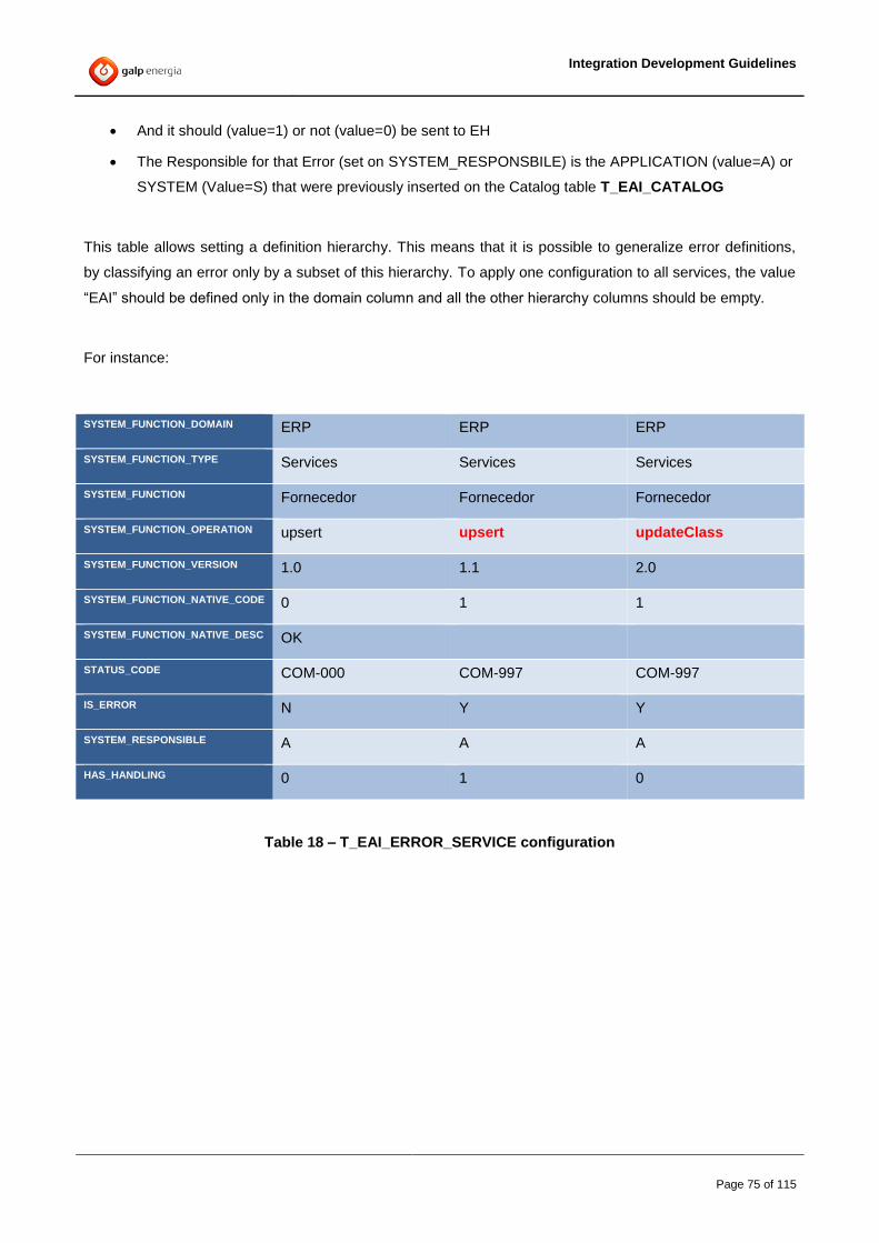
Integration Development Guidelines
Page 75 of 115
And it should (value=1) or not (value=0) be sent to EH
The Responsible for that Error (set on SYSTEM_RESPONSBILE) is the APPLICATION (value=A) or
SYSTEM (Value=S) that were previously inserted on the Catalog table T_EAI_CATALOG
This table allows setting a definition hierarchy. This means that it is possible to generalize error definitions,
by classifying an error only by a subset of this hierarchy. To apply one configuration to all services, the value
“EAI” should be defined only in the domain column and all the other hierarchy columns should be empty.
For instance:
SYSTEM_FUNCTION_DOMAIN ERP ERP ERP
SYSTEM_FUNCTION_TYPE Services Services Services
SYSTEM_FUNCTION Fornecedor Fornecedor Fornecedor
SYSTEM_FUNCTION_OPERATION upsert upsert updateClass
SYSTEM_FUNCTION_VERSION 1.0 1.1 2.0
SYSTEM_FUNCTION_NATIVE_CODE 0 1 1
SYSTEM_FUNCTION_NATIVE_DESC OK
STATUS_CODE COM-000 COM-997 COM-997
IS_ERROR N Y Y
SYSTEM_RESPONSIBLE A A A
HAS_HANDLING 0 1 0
Table 18 – T_EAI_ERROR_SERVICE configuration
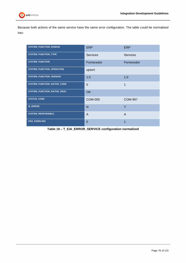
Integration Development Guidelines
Page 76 of 115
Because both actions of the same service have the same error configuration. The table could be normalized
into:
SYSTEM_FUNCTION_DOMAIN ERP ERP
SYSTEM_FUNCTION_TYPE Services Services
SYSTEM_FUNCTION Fornecedor Fornecedor
SYSTEM_FUNCTION_OPERATION upsert
SYSTEM_FUNCTION_VERSION 1.0 1.0
SYSTEM_FUNCTION_NATIVE_CODE 0 1
SYSTEM_FUNCTION_NATIVE_DESC OK
STATUS_CODE COM-000 COM-997
IS_ERROR N Y
SYSTEM_RESPONSIBLE A A
HAS_HANDLING 0 1
Table 19 – T_EAI_ERROR_SERVICE configuration normalized

Integration Development Guidelines
Page 77 of 115
As so, when checking for an error the algorithm follows the following decision tree:
Yes
Start
End
Error has
Action
configured?
Error has
service
configured?
Error has type
configured?
Error has
domain
configured?
Error has
error_catalog
configured?
No
No
No
No
Set Status with
Unknown Error
No
Set Status with
the configured
Error
Yes
Yes
Yes
Yes
Figure 34 – EAI Error Service algorithm
For each Project, the document “PIGENT15 – Error Configuration” must be sent with the entire
configuration that should be inserted on this table
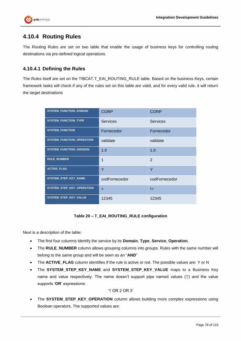
Integration Development Guidelines
Page 78 of 115
4.10.4 Routing Rules
The Routing Rules are set on two table that enable the usage of business keys for controlling routing
destinations via pre-defined logical operations.
4.10.4.1 Defining the Rules
The Rules itself are set on the TIBCAT.T_EAI_ROUTING_RULE table. Based on the business Keys, certain
framework tasks will check if any of the rules set on this table are valid, and for every valid rule, it will return
the target destinations
SYSTEM_FUNCTION_DOMAIN CORP CORP
SYSTEM_FUNCTION_TYPE Services Services
SYSTEM_FUNCTION Fornecedor Fornecedor
SYSTEM_FUNCTION_OPERATION validate validate
SYSTEM_FUNCTION_VERSION 1.0 1.0
RULE_NUMBER 1 2
ACTIVE_FLAG Y Y
SYSTEM_STEP_KEY_NAME codFornecedor codFornecedor
SYSTEM_STEP_KEY_OPERATION = !=
SYSTEM_STEP_KEY_VALUE 12345 12345
Table 20 – T_EAI_ROUTING_RULE configuration
Next is a description of the table:
The first four columns identify the service by its Domain, Type, Service, Operation.
The RULE_NUMBER column allows grouping columns into groups. Rules with the same number will
belong to the same group and will be seen as an “AND”
The ACTIVE_FLAG column identifies if the rule is active or not. The possible values are: Y or N
The SYSTEM_STEP_KEY_NAME and SYSTEM_STEP_KEY_VALUE maps to a Business Key
name and value respectively. The name doesn’t support pipe named values (‘|’) and the value
supports ‘OR’ expressions:
‘1 OR 2 OR 3’
The SYSTEM_STEP_KEY_OPERATION column allows building more complex expressions using
Boolean operators. The supported values are:

Integration Development Guidelines
Page 79 of 115
o = (equals)
o != (not equals)
o > (greater than)
o < (lower than)
o >= (greater or equal than)
o <= (lower or equal than)
o contains
o starts-with
o always (this triggers the rule always, independently of the Business Keys values.
If more than one rule exists for one service, and all conditions match, then all matching rules will be
triggered.
4.10.4.2 Defining the Destinations
The Destinations that are returned for each valid rule are set on the
TIBCAT.T_EAI_ROUTING_DESTINATION table. This table controls the routing of events and requests by
containing the destinations-endpoint information for a specific event or request
SYSTEM_FUNCTION_DOMAIN CORP CORP
SYSTEM_FUNCTION_TYPE Services Services
SYSTEM_FUNCTION Fornecedor Fornecedor
SYSTEM_FUNCTION_OPERATION validate validate
SYSTEM_FUNCTION_VERSION 1.0 1.0
RULE_NUMBER 1 2
ACTIVE_FLAG Y Y
DEST_SYSTEM_FUNCTION_DOMAIN ERP ERP
DEST_SYSTEM_NAME_CONNECTED OPENSGC SAPPI
RULE_TYPE D D
Table 21 – T_EAI_ROUTING_DESTINATION configuration
Next is a description of the table:
The first four columns identify the service by its Domain, Type, Service, Operation.
The RULE_NUMBER column identifies the destination id that will be triggered. This id must match
with the id defined in the T_EAI_ROUTING_RULE table.

Integration Development Guidelines
Page 80 of 115
The ACTIVE_FLAG column identifies if the rule is active or not. The possible values are: Y or N
DEST_SYSTEM_FUNCTION_DOMAIN and DEST_SYSTEM_NAME_CONNECTED are the values
returned by the rule.
RULE_TYPE identifies the type of the rule.
Depending on the RULE_TYPE Value, a different Framework task should be used as it can be seen
on the next table
Type Value on
the Table
Description Framework Task(s) to use
Destination D Use to route to target destinations
Source S Used to identify the Origin applications that
invoked the service/Interface
Other O used for dynamic variables if there is a need to
change variables without a need to restart the
components
Table 22 – RULE_TYPE field configuration
4.10.4.3 Specifying Additional Destinations (Filter on Header)
Whenever a source system wants to specify a specific target back-end system it should use the
Header.Filter.destination element.
Figure 35 – Destination filter elements
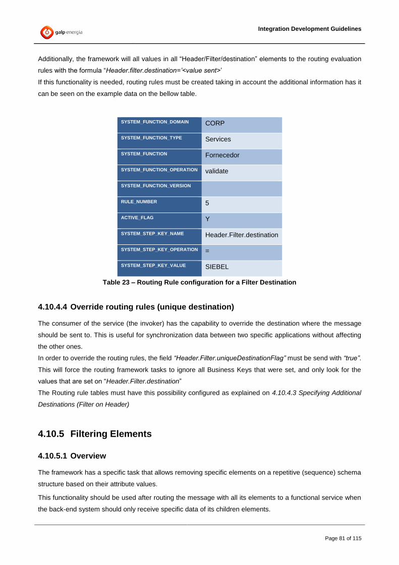
Integration Development Guidelines
Page 81 of 115
Additionally, the framework will all values in all “Header/Filter/destination” elements to the routing evaluation
rules with the formula “Header.filter.destination=’<value sent>’
If this functionality is needed, routing rules must be created taking in account the additional information has it
can be seen on the example data on the bellow table.
SYSTEM_FUNCTION_DOMAIN CORP
SYSTEM_FUNCTION_TYPE Services
SYSTEM_FUNCTION Fornecedor
SYSTEM_FUNCTION_OPERATION validate
SYSTEM_FUNCTION_VERSION
RULE_NUMBER 5
ACTIVE_FLAG Y
SYSTEM_STEP_KEY_NAME Header.Filter.destination
SYSTEM_STEP_KEY_OPERATION =
SYSTEM_STEP_KEY_VALUE SIEBEL
Table 23 – Routing Rule configuration for a Filter Destination
4.10.4.4 Override routing rules (unique destination)
The consumer of the service (the invoker) has the capability to override the destination where the message
should be sent to. This is useful for synchronization data between two specific applications without affecting
the other ones.
In order to override the routing rules, the field “Header.Filter.uniqueDestinationFlag” must be send with “true”.
This will force the routing framework tasks to ignore all Business Keys that were set, and only look for the
values that are set on “Header.Filter.destination”
The Routing rule tables must have this possibility configured as explained on 4.10.4.3 Specifying Additional
Destinations (Filter on Header)
4.10.5 Filtering Elements
4.10.5.1 Overview
The framework has a specific task that allows removing specific elements on a repetitive (sequence) schema
structure based on their attribute values.
This functionality should be used after routing the message with all its elements to a functional service when
the back-end system should only receive specific data of its children elements.

Integration Development Guidelines
Page 82 of 115
4.10.5.2 Configuration
The TIBCOCAT.T_EAI_FILTERS table will contain filtering rules that can be applied for a specific service.
SYSTEM_FUNCTION_DOMAIN CRM CRM
SYSTEM_FUNCTION_TYPE Services Services
SYSTEM_FUNCTION Customer Customer
SYSTEM_FUNCTION_OPERATIO
N
upsert upsert
SYSTEM_FUNCTION_VERSION 1.0 1.0
FILTER_ID Energy Customer
FILTER_ELEMENT Account Account
FILTER_CONDITION current()[(@type='GAZ' or @type='OIL’)] current()[(@type='Customer')]
ACTIVE Y Y
Table 24 – T_EAI_FILTERS table
Next is a brief description of the columns:
DOMAIN: Identifies the domain (business/functional) that is associated to the component where the
transaction step was executed.
SERVICE: Defines the name of the runtime interaction point.
ACTION: Defines the operation of the runtime interaction point
FILTER_ID: Identifier of the Filtering rule, if the same FILTER_ID exists for the same endpoint
(Domain, Service, Action), all rules with the same FILTER_ID will be executed.
ELEMENT: Name of the Element where the condition will be applied.
CONDITION: the XPATH condition that identifies which elements should be maintained
ACTIVE: Identifies if the filtering rule is active or not. The possible values are: Y or N
4.10.5.3 Framework Task
The framework task “applyFilters” only applies the rules that are set for the current service.
Figure 36 – Apply Filters framework task

Integration Development Guidelines
Page 83 of 115
It has 2 input fields:
ID, (repetitive) : If set, only the rules with these IDs will be used, in order (top to bottom), if null then
all rules of the current service will be executed, ordered by the FILTER_ID in ascending order.
fullMessage (mandatory): Must be a rendered XML (single line of text) of the XML message the
rules should be applied to.
The task returns a rendered XML text with the filtered results.
4.10.5.4 Example
The following presents a possible example based on a fictitious scenario:
1 – According to a business scenario all Enterprise Customers and only its Energy type Accounts should be
updated on the back-end system whenever there is a change on the Customer Data.
2 – To achieve this, the Customer Master Data system sends the Customer data every time there is a new
customer creation or a change on existing ones.
Customer
@id = “111”
@type = “Enterprise”
Account
@id = “A1”
@type = “OIL”
Account
@id = “A2”
@type = “Customer”
Account
@id = “A3”
@type = “GAZ”
Back-End System
Send to
Figure 37 – Sending all Data to Back-end System
3 – The Data sent however contains all its Accounts, including Energy type and others, since that account
information might be useful for other Back-end systems.
4 – When the Data reaches orchestration (CORP domain) level, one of the routing rules will be to send to
this Back-End system functional domain service all Customers of type “Enterprise”
5 – The functional domain service will then run the filter rules that retrieves all Account Elements that belong
to Energy type Accounts (OIL and GAZ) while removing all the others.
This is done by Applying the Xpath formula “current()[(@type='GAZ' or @type='OIL’)]” on the “Account”
element.

Integration Development Guidelines
Page 84 of 115
Customer
@id = “111”
@type = “Enterprise”
Account
@id = “A1”
@type = “OIL”
Account
@id = “A2”
@type = “Customer”
Account
@id = “A3”
@type = “GAZ”
Back-End System
Send to
Customer
@id = “111”
@type = “Enterprise”
Account
@id = “A1”
@type = “OIL”
Account
@id = “A3”
@type = “GAZ”
Filter rules:
ELEMENT=”Account”
CONDITION=current()[(@type='GAZ' or @type='OIL’)]”
Apply Result
Figure 38 – Filtering the data before sending to the Back-End System
4.11 Unified Logging
This section focuses on the centralized logging tables.
4.11.1 EAI_LOG_HEADER
Main Unified LOG table that holds information for each step executed within a transaction.
The logged information follows the “step” logic. This means that for each interaction with an application that
logs to Unifued LOG, a new line will be added in this table.
A “step” is uniquely identified by a LOG_ ID, and describes the SERVICE it refers to, the “step” start time and
duration, as well as the execution code.
LOG_ID L1 L2 L3 L4
TRACKING_ID T0001 T0001 T0001 T0001
STEP 1 2 3 4
COMPONENT SAPPI BW BW BW
COMPONENT_NAME sappid01 repo.ERP repo.CORP repo.EC
DOMAIN SAPPI ERP CORP EC
TYPE Interfaces Services Services Services

Integration Development Guidelines
Page 85 of 115
SERVICE bpmInvoiceSend ZINVOIC02 Factura Factura
ACTION publish publish send send
STARTTIME
2012-05-08 10:41:36.6 2012-05-08 10:41:37.279 2012-05-08
10:41:37.337
2012-05-08
10:41:37.368
ENDTIME
ECODE COM-000 COM-000 COM-000 COM-500
EDESCRIPTION Success Success Success Timeout
NCODE 0 BW-ENGINE-XXX
NDESCRIPTION Timeout while executing
TRACE <long trace>
ERRORID E1111
APPLICATION IXOS
ISERROR 0 0 0 1
VER_FW 2.3.7 2.3.7 2.3.7 2.3.7
VER_SR 2 2 2 2
VER_CDM 2.23 2.23 2.23 2.23
OUT_SLA 0 0 0 1
STATUS_RESP IXOS
HAS_DEBUG 1
Table 25 – EAI_LOG_HEADER logging table
Next is a brief description of the columns:
LOG_ID: Unique GUID key log identifier that ultimately identifies a step (SYSTEM_STEP) within a
transaction, and all associated data.
APPLICATION: Unique connecting system identifier.
TRACKING_ID: The internal tracking id is a GUID that is common to all steps within a transaction. A
TRACKING_ID can be related to 1 or more LOG _IDs which means that one transaction can have 1
or more steps.
STEP: The system step identifies the order of the steps of the transaction over several systems.
COMPONENT: Identifies the type of component where the transaction step was executed.
COMPONENT_NAME: Identifies the runtime component where the transaction step was executed.

Integration Development Guidelines
Page 86 of 115
DOMAIN: Identifies the domain (business/functional) that is associated to the component where the
transaction step was executed.
TYPE: Defines the type of the runtime interaction point. E.g. Process, Interface, Service.
SERVICE: Defines the name of the runtime interaction point.
ACTION: If applicable (e.g. if type=service), defines the operation of the runtime interaction point.
STARTTIME: Defines the dateTime up to the millisecond of the transaction step that entered the
runtime iteration point represented by: DOMAIN, TYPE, SERVICE, ACTION,
ENDTIME: Defines the dateTime up to the millisecond of the transaction step that leaved the runtime
iteration point represented by: DOMAIN, TYPE, SERVICE, ACTION,
ECODE: Application canonical execution code.
EDESCRIPTION: Application canonical description message.
NCODE: Application native execution code.
NDESCRIPTION: Application native description message.
ISERROR: Flag that identifies if that entry finished with an error or not.
VER_FW: The framework version that processed the log information.
VER_SR: SharedResources Library Version that was used
VER_CDM: CDM Library version( currently not used)
OUT_SLA: Indicates if the service finished in time or out of the pre-defined SLA on the CATALOG
table
STATUS_RESP: Application responsible for this error or success.
PARTITION_DATE: Partition date used to manage history tablespaces.
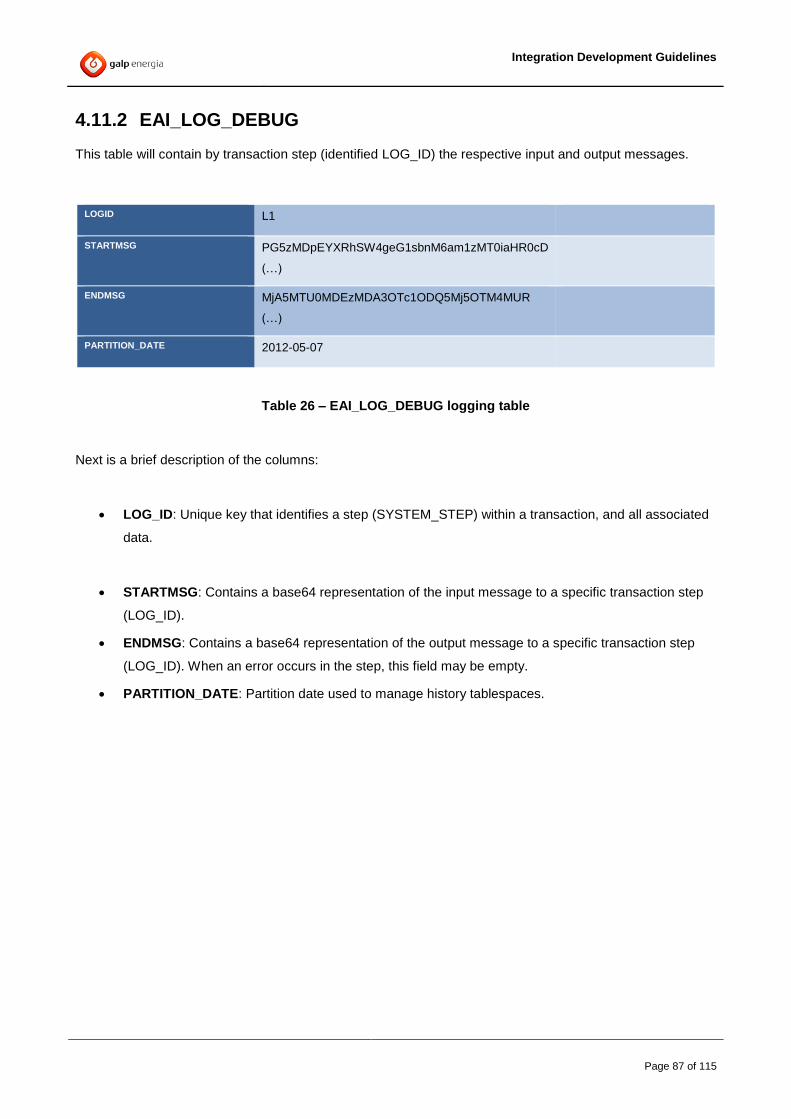
Integration Development Guidelines
Page 87 of 115
4.11.2 EAI_LOG_DEBUG
This table will contain by transaction step (identified LOG_ID) the respective input and output messages.
LOGID L1
STARTMSG PG5zMDpEYXRhSW4geG1sbnM6am1zMT0iaHR0cD
(…)
ENDMSG MjA5MTU0MDEzMDA3OTc1ODQ5Mj5OTM4MUR
(…)
PARTITION_DATE 2012-05-07
Table 26 – EAI_LOG_DEBUG logging table
Next is a brief description of the columns:
LOG_ID: Unique key that identifies a step (SYSTEM_STEP) within a transaction, and all associated
data.
STARTMSG: Contains a base64 representation of the input message to a specific transaction step
(LOG_ID).
ENDMSG: Contains a base64 representation of the output message to a specific transaction step
(LOG_ID). When an error occurs in the step, this field may be empty.
PARTITION_DATE: Partition date used to manage history tablespaces.

Integration Development Guidelines
Page 88 of 115
4.11.3 EAI_LOG_KEY
This table will contain the business keys for a specific transaction step (LOG_ID).
LOG_ID L1 L2 L2 L2
GROUP_ID 1 1 1 1
FIELD INVOICNUM Factura.numFactura Factura.codEmpresa Factura.tipo
VALUE 1696653 1696653 100616 Email
TRACKINGID T0001 T0001 T0001 T0001
PARTITION_DATE 2012-05-07 2012-05-07 2012-05-07 2012-05-07
Table 27 – EAI _LOG_KEY logging table
Next is a brief description of the columns:
LOG_ID: Unique key that identifies a step (SYSTEM_STEP) within a transaction, and all associated
data.
GROUP_ID: This field can be used in correlations between business keys.
FIELD: Identifies the name of the business key.
VALUE: Identifies the value of the business key.
TRACKING_ID: The internal tracking id to ease the search of all Business Keys on the same
Transaction
PARTITION_DATE: Partition date used to manage history table spaces.
4.11.4 EAI_LOG_DESTINATION
This table will be used whenever the RouteEvent task (or RouteEvent and Forward) are used
A line will be inserted for each destination returned by these tasks
TRACKINGID T0002
DESTINATIONDOMAIN AQS
DESTINATIONAPP iBPMS

Integration Development Guidelines
Page 89 of 115
Table 28 – EAI_LOG_DESTINTION table
Next is a brief description of the columns:
TRACKINGID: The internal tracking id to ease the search of all Destinations on the same
Transaction
DESTINATIONDOMAIN: The name of the DOMAIN returned
DESTINATIONAPP: The name of the application returned
4.12 Additional Framework Schemas
4.12.1 TIBEH Schema
The TIBEH Schema contains all necessary tables for the Error Handling Component.
For more information please check the Error Handling Documentation.
4.12.2 TIBCOBAM Schema
The TIBCOBAM Schema contains all necessary tables for the BAM components and Architecture.
For more information please check the BAM Documentation.
4.12.3 LOGMON Schema
The LOGMON Schema contains all necessary tables for the GALP EWU control platform that is accessible
by the “mygalp” intranet site.
For more information please check the EWU’s Documentation.
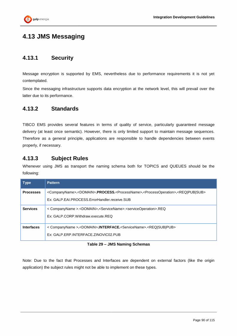
Integration Development Guidelines
Page 90 of 115
4.13 JMS Messaging
4.13.1 Security
Message encryption is supported by EMS, nevertheless due to performance requirements it is not yet
contemplated.
Since the messaging infrastructure supports data encryption at the network level, this will prevail over the
latter due to its performance.
4.13.2 Standards
TIBCO EMS provides several features in terms of quality of service, particularly guaranteed message
delivery (at least once semantic). However, there is only limited support to maintain message sequences.
Therefore as a general principle, applications are responsible to handle dependencies between events
properly, if necessary.
4.13.3 Subject Rules
Whenever using JMS as transport the naming schema both for TOPICS and QUEUES should be the
following:
Type Pattern
Processes <CompanyName>.<DOMAIN>.PROCESS.<ProcessName>.<ProcessOperation>.<REQ|PUB|SUB>
Ex: GALP.EAI.PROCESS.ErrorHandler.receive.SUB
Services < CompanyName >.<DOMAIN>.<ServiceName>.<serviceOperation>.REQ
Ex: GALP.CORP.Withdraw.execute.REQ
Interfaces < CompanyName >.<DOMAIN>.INTERFACE.<ServiceName>.<REQ|SUB|PUB>
Ex: GALP.ERP.INTERFACE.ZINOVIC02.PUB
Table 29 – JMS Naming Schemas
Note: Due to the fact that Processes and Interfaces are dependent on external factors (like the origin
application) the subject rules might not be able to implement on these types.

Integration Development Guidelines
Page 91 of 115
The patterns must respect the following subject rules:
Subject Tokens Suggested Values Rationale
CompanyName Global Variable
SharedVariables/DefaultVariables/SubjectPrefix
Uniquely identifies subjects managed by
GALP.
Domain
ERP
SAPPI
CORP
APP_OPENSGC
Domains allow more decentralized
management of the subject space within an
organization. They may also be indicative of
the kinds of messages that are being
published.
One way to look at subject domains is to
view each domain as a segment of the
“subject name space” in which a common
set of naming policies and message
schemas is applied. This means that the
manager of each domain can independently
define the details of that domain’s subject
naming policy and message schema policy.
Because the domain name is part of the
subject, naming conflicts will not arise
between domains.
ServiceName
or
InterfaceName
Or
ProcessName
Services (SOA):
Factura,
Cliente,
etc.
Interface:
ZINVOIC02,
bpmSageIn,
etc.
This token identifies the service or Interface
Name that the QUEUE or TOPIC belongs
to.
Service Operation
or
Interface Operation
Services Operation:
upsert,
get,
etc.
Interface
Operation:
execute
etc.
This token identifies the service or interface
operation that the QUEUE or TOPIC
belongs to.
Table 30 – JMS Naming Rules
4.13.4 Service Implementation
Framework services (not required for processes and interfaces but recommended) that are available on the
framework must follow these rules:
Common to all paradigms:

Integration Development Guidelines
Page 92 of 115
1- The SOAP Action must always be the name of the “action” preceded by a slash “/”
Eg: For service Documento.getContent the SOAP action must be “/send”
2- The JMS Message Type must be set to “Bytes Message”
3- The Style/Encoding should be “Document/literal”
4- The SOAP version is 1.1
5- The Acknowledge mode should be primarily set to “auto”. If explicit confirmation is needed then
“Client” is allowed.
When invoking a service synchronously:
1- The delivery mode should be “TIBCO EMS RELIABLE DELIVERY” or , for clients that don’t accept
this configuration (and only for those), “NON PERSISTENT”
When invoking a service asynchronously:
1- The delivery mode should be “PERSISTENT”
TIBCO EMS request reply
DEV 11- TIBCO EMS Delivery mode
The following EMS properties must be used:
Invoking Synchronous services:
Delivery mode: TIBCO EMS RELIABLE DELIVERY
Acknowledge mode: Auto
Invoking Asynchronous services:
Delivery mode: PERSISTENT
Acknowledge mode: Auto or Client
4.14 Hawk Rules Development
Hawk Rules must be designed having into account their re-usability. In order to simplify rules management
and deployment procedures, the Service Framework assumes 2 types of rules:
Hawk Agent Rules
Product specific rules
Integration Development Guidelines
Page 93 of 115
4.14.1 Hawk Agent rules
These are rules that do not apply to all deployed engines. For instance: a rule that monitors a specific
environment characteristic and isn’t related to a specific engine.
These rules are deployed directly to the domain hawk agent
4.14.2 Product specific rules
A product specific rule is a rule that only applies for a type of Tibco product. For instance: BW Engine rules,
ADB rules, etc.
All monitoring rules defined for BW Engines product type should be designed in a way that allows it to be
deployed to every running BW engine.
The same logic applies to other available products.
4.14.3 Developing Hawk Rules
Detailed documentation can be found in Hawk official documentation, the following steps should be seen as
a quick guide on how it is expected to develop Hawk rules in the Service Framework:
Hawk Rules should be developed using tibhawkdisplay.
After creating your rule save it to the filesystem. This should create an HRB file.
Create a MAR file using the mar utility ($HAWK_HOME/bin). E.g.:
mar cvdf "Rules for Tibco Hawk Agent" "TibcoHawkAgent-Rules-asis.mar"
../rulebases/TibcoHawkAgent-Rules.hrb –Xasis
Deploy the MAR file into your targets using the Tibco Administrator GUI.

Integration Development Guidelines
Page 94 of 115
5 TIBCO Components
5.1 Overview
After identifying and developing all necessary Domains, Services and Interfaces, the distribution of these
components through TIBCO components (BusinessWorks, Adapters, etc) should be made according to
standardized rules.
This normalization will allow all involved teams (Development, Maintenance, etc) to easily understand the
existing Infrastructure and eventually optimize working processes to improve both quality and speed of their
work.
5.2 Component Naming
All Tibco components must follow the following standard nomenclature:
<COMPONENT ABREVIATION>_<DOMAIN>_[TYPE]_[OPTIONAL FIELDS]
Where Component Abbreviation should be one of the following:
Component Abbreviation
BusinessWorks BW
Adapter for Database ADB
Adapter for SAP R3A
Adapter for Siebel ADSBL
Table 31 – TIBCO Component Name abbreviations
The TYPE is used to better identify a specific component whenever such identification is needed.
5.2.1 BusinessWorks
DEV 12- TIBCO Business Works components
Each Business works component must belong to a single EAR file.
Unless approved by the architecture, it can only have services and Interfaces of a single Domain.
Also, to allow load balancing, all development should be designed to allow Load balancing or, on specific scenarios, fault tolerance.

Integration Development Guidelines
Page 95 of 115
Name wise it should follow one of the allowed rules:
One BusinessWorks engine with all the Domain services and interfaces. (example: BW_DOMAIN)
A BusinessWorks based on type. One with all services and other with all Interfaces (example:
BW_DOMAIN_SERVICES and BW_DOMAIN_INTERFACE)
BusinessWorks engines based on business Logical grouping (example: BW_FACTURA or
BW_MASTERDATA,etc). In order to group services in this way, the project will need specific GALP
DSI Architecture approval.
For splitting reasons, if needed, a number could be added at the end (example: BW_DOMAIN_1,
BW_DOMAIN_2, etc.)
A mix of several solutions might also be allowed. (example: BW_DOMAIN_FACTURA).
Additionally, specific Processes should run standalone on a single BusinessWorks engine. This may occur
due to specific technical requirements (e.g. memory usage, workload, etc.). On these scenarios the name
should contain the Domain where the process belongs to and a suffix indicating its functionality. (e.g.:
BW_EAI_HTTP2JMS or BW_EAI_GATEWAY)
5.2.2 Adapters
TIBCO Adapters on the other hand, not only must belong to a single domain, but must also be grouped by a
specific service type. This means that the same adapter should not have both Publishing and Subscription
services incorporated.
By using the < ADAPTER ABREVIATION >_< DOMAIN >_[ APP | FUNCTION ]_[ TYPE ] convention:
The APP field is optional and it should only be used when there is a need to identify which application of that
domain the adapter is connected to.
Example:
ADB_WEB_XYZ_REQ – The WEB Functional Domain has an Active Database Adapter that
connects directly to the XYZ database.
ADB_EAI_LOG_SUB – The EAI Functional Domain has an Active Database Adapter that is
subscribing messages directly to the LOG database (or schema).
The TYPE should be one of the following:
Publishing [PUB] – When the client System Publishes a message to the EAI and It doesn’t wait for
a reply (aka: as EDA or Advanced SOA).
Requesting [SRV] – When a client system needs an adapter to make a request to a synchronous
EAI service.
Retrieving [REQ] – When the EAI wants to retrieve information from the end system synchronously.
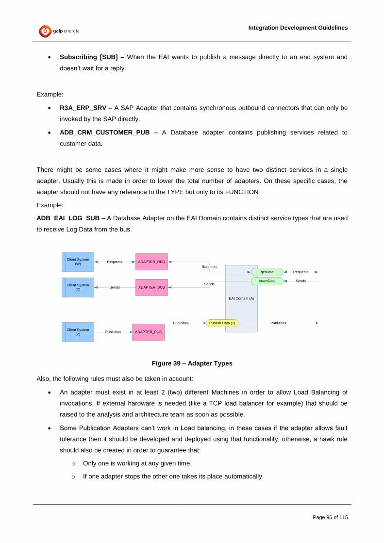
Integration Development Guidelines
Page 96 of 115
Subscribing [SUB] – When the EAI wants to publish a message directly to an end system and
doesn’t wait for a reply.
Example:
R3A_ERP_SRV – A SAP Adapter that contains synchronous outbound connectors that can only be
invoked by the SAP directly.
ADB_CRM_CUSTOMER_PUB – A Database adapter contains publishing services related to
customer data.
There might be some cases where it might make more sense to have two distinct services in a single
adapter. Usually this is made in order to lower the total number of adapters. On these specific cases, the
adapter should not have any reference to the TYPE but only to its FUNCTION
Example:
ADB_EAI_LOG_SUB – A Database Adapter on the EAI Domain contains distinct service types that are used
to receive Log Data from the bus.
EAI Domain (A)
Publish Data (1)
Client System
(W)
Client System
(X)
Client System
(Z)
Requests
Sends
Publishes
getData
InsertData
ADAPTER_PUB
Publishes
ADAPTER_SUB
ADAPTER_REQ
Requests
Sends
Requests
Sends
Publishes
Figure 39 – Adapter Types
Also, the following rules must also be taken in account:
An adapter must exist in at least 2 (two) different Machines in order to allow Load Balancing of
invocations. If external hardware is needed (like a TCP load balancer for example) that should be
raised to the analysis and architecture team as soon as possible.
Some Publication Adapters can’t work in Load balancing, in these cases if the adapter allows fault
tolerance then it should be developed and deployed using that functionality, otherwise, a hawk rule
should also be created in order to guarantee that:
o Only one is working at any given time.
o If one adapter stops the other one takes its place automatically.

Integration Development Guidelines
Page 97 of 115
Appendix A. Service development steps
This section aims to enumerate the main steps in a service creation from scratch. It assumes that an existing
service already exists on the same domain and that it will be used as a starting base for new service
development:
A. Preparing
Identify a <DOMAIN> service for which the logic is more similar to the new service to be
implemented.
In the file system (not designer), copy-paste the service folder.
Rename it to the new service name
o Remember the old (original) name
o Remember to follow the naming conventions
Delete all folders inside the service folder that belong to exceeding operations (actions), leaving
only one.
Rename the remaining action folder to the target action folder
For each folder deleted, go to the WSDL under “_ServiceSchemas/WSDL/serviceWSDL”
o Select the “PortType” and delete all operations that were deleted on the previous step.
Rename the remaining portType to the target action (that should be the same as the folder)
B. Creating the new service and action names
Using a file editor (pspad, ultraEdit, notepad+, etc), select the newly created folder as the start
point and do a search in all files, including subfolders. The options should be:
o Search for the original service name,
o Replace it with the new service name.
o (note that the case should be sensitive search)
Using a file editor, do a search in files, on the new action folder inside the service folder, for
the original action name, and replace it with the new action name. Mind the case sensitive
search.
C. Develop the service
Change the operation’s Data.xsd schema in order to comply with the new service specification.
Only CDM element definitions should be used.
The logical process in order to comply with the new service specification.
Change the tester process tester.process in order to simulate a request.
Integration Development Guidelines
Page 98 of 115
Validate the project using designer’s validation functionality
D. Configure the service
Create the necessary JMS queues in EMS server.
Configure the service using the Catalog/Services module in EWU.
Configure the functional error definitions in the Catalog/Errors module in EWU.
E. Test the Service
Test the service using the designer tester functionality.
F. Make the service available to others
Add the Internal call process starter to the domain Serviceschemas.<DOMAIN> DTL (check
Annex B)
Add the service to the EAR by adding to the repo.BW_<DOMAIN> deployment EAR file.
o process starter
o logical process
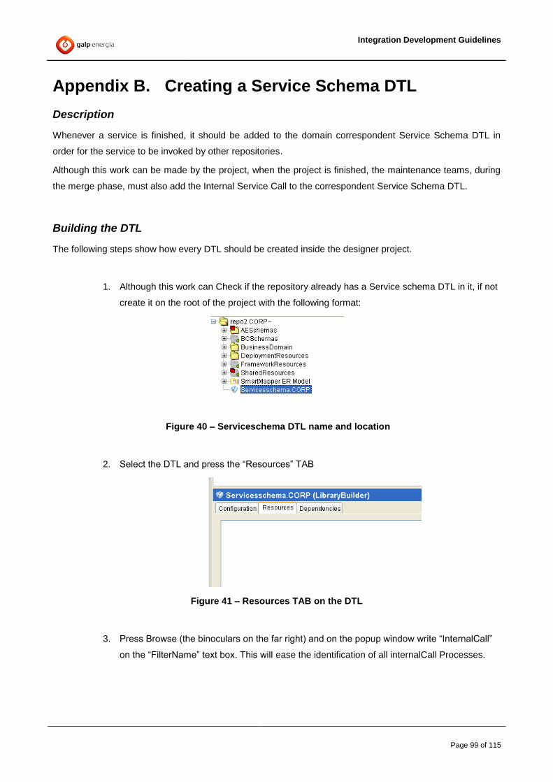
Integration Development Guidelines
Page 99 of 115
Appendix B. Creating a Service Schema DTL
Description
Whenever a service is finished, it should be added to the domain correspondent Service Schema DTL in
order for the service to be invoked by other repositories.
Although this work can be made by the project, when the project is finished, the maintenance teams, during
the merge phase, must also add the Internal Service Call to the correspondent Service Schema DTL.
Building the DTL
The following steps show how every DTL should be created inside the designer project.
1. Although this work can Check if the repository already has a Service schema DTL in it, if not
create it on the root of the project with the following format:
Figure 40 – Serviceschema DTL name and location
2. Select the DTL and press the “Resources” TAB
Figure 41 – Resources TAB on the DTL
3. Press Browse (the binoculars on the far right) and on the popup window write “InternalCall”
on the “FilterName” text box. This will ease the identification of all internalCall Processes.

Integration Development Guidelines
Page 100 of 115
Figure 42 – Browse and filter Internal Calls
4. Select all Services “internalCall” processes (you can select multiple ones by holding doen
the CTRL key) Note: Don’t select any process from “SharedResources”
Figure 43 – Select services “Internal Calls”
Integration Development Guidelines
Page 101 of 115
5. After adding all Internal Calls press OK on the popup window, and afterwards apply the
configuration on the DTL and press “Build Library”
Note: At this point, the library is created. However, it still needs some tuning because the DTL also adds
some references to the SharedLibrary which must be removed before making the DTL available to other
repositories
Fixing the DTL
The following steps show how to remove the extra resources that were added by designer.
1. Locate the “Serviceschemas.<DOMAIN>.projlib” file on Windows Explorer (or similar)
2. Open it with a zip tool (winzip, wirar or similar)
3. Remove the SharedResources folder from the file
4. Remove the defaultVars folder from the file
5. Save
After these steps, the library can now be added to TFS and be used by all projects.
Note: failure in doing this fix might lead to having out-of-sync CDM schemas.
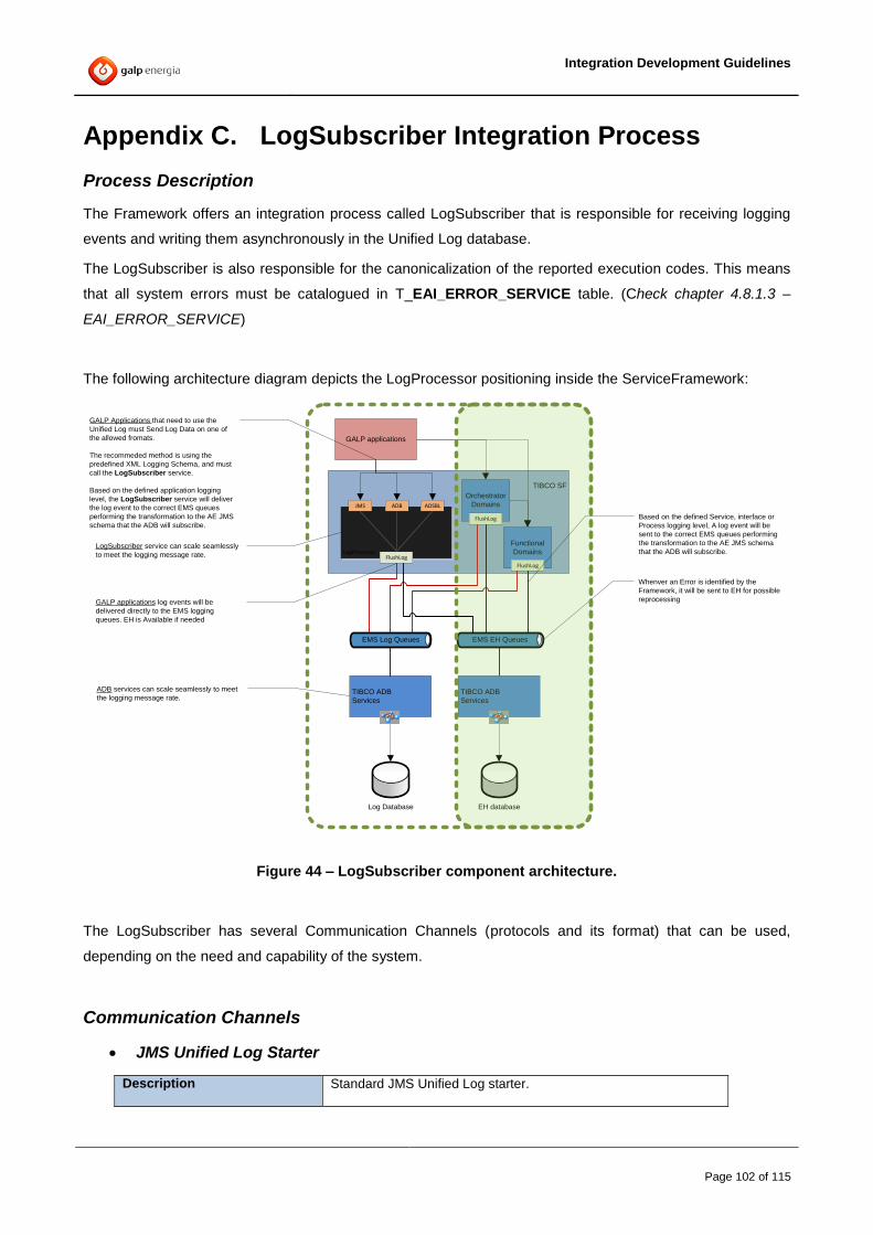
Integration Development Guidelines
Page 102 of 115
Appendix C. LogSubscriber Integration Process
Process Description
The Framework offers an integration process called LogSubscriber that is responsible for receiving logging
events and writing them asynchronously in the Unified Log database.
The LogSubscriber is also responsible for the canonicalization of the reported execution codes. This means
that all system errors must be catalogued in T_EAI_ERROR_SERVICE table. (Check chapter 4.8.1.3 –
EAI_ERROR_SERVICE)
The following architecture diagram depicts the LogProcessor positioning inside the ServiceFramework:
EH databaseLog Database
TIBCO SF
GALP applications
LogProcessor
ADBJMS ADSBL
Orchestrator
Domains
Functional
Domains
EMS EH Queues
TIBCO ADB
Services
TIBCO ADB
Services
FlushLog
EMS Log Queues
FlushLog Based on the defined Service, interface or
Process logging level, A log event will be
sent to the correct EMS queues performing
the transformation to the AE JMS schema
that the ADB will subscribe.
Whenver an Error is identified by the
Framework, it will be sent to EH for possible
reprocessing
GALP Applications that need to use the
Unified Log must Send Log Data on one of
the allowed fromats.
The recommeded method is using the
predefined XML Logging Schema, and must
call the LogSubscriber service.
Based on the defined application logging
level, the LogSubscriber service will deliver
the log event to the correct EMS queues
performing the transformation to the AE JMS
schema that the ADB will subscribe.
GALP applications log events will be
delivered directly to the EMS logging
queues. EH is Available if needed
LogSubscriber service can scale seamlessly
to meet the logging message rate.
ADB services can scale seamlessly to meet
the logging message rate.
FlushLog
Figure 44 – LogSubscriber component architecture.
The LogSubscriber has several Communication Channels (protocols and its format) that can be used,
depending on the need and capability of the system.
Communication Channels
JMS Unified Log Starter
Description Standard JMS Unified Log starter.

Integration Development Guidelines
Page 103 of 115
Used by SAP-PI and all applications that are able to send
messages to JMS queues directly.
This Channel is also used by the Framework Task “Send to Log
Subscriber”
Transport JMS
Type Queue Receiver
EMS Async
Queue / Subject GALP.EAI.LogSubscriber.SUB
Message Type XML Text
Delivery Mode PERSISTENT
ADB Starter
Description
The Framework on the repo2.EAI has available a generic
Database Publisher Adapter called ADB_EAI_LOG_PUB that can
be used to publish unified DB log data from the source systems to
the Unified Log.
This starter will be Used by all
ADB_EAI_LOG_PUB_<Application> database adapters that are
copies of the standard ADB_EAI_LOG_PUB one.
Transport JMS
Type Queue Receiver
EMS Async
Queue / Subject GALP.EAI.ADB_EAI_LOG_EAI_LOG_HEADER.PUB
Message Type AE schema
Delivery Mode PERSISTENT
ADSBL Starter
Description
Whenever Siebel needs to publish a unified log message it does
so by inserting a line on its specific BC.
The ADSBL_CRM_LOG_PUB TIBCO Siebel adapter will publish
those messages automatically has they are made available.
This starter Receiver of Siebel Log Messages

Integration Development Guidelines
Page 104 of 115
Whenever Siebel needs to publish a message to the Unfied
Transport JMS
Type Queue Receiver
EMS Async
Queue / Subject GALP.CRM.Siebel.OGR_Siebel_log_TIBCO.PUB
Message Type AE schema
Delivery Mode PERSISTENT
JMS/XML Message
The following table summarizes the Standard JMS/XML Log Message:
Element Detail
Log schema
Elements Detail
Main Element Elements/attributes Description Mandatory
Log \ logID Unique GUID log identifier, which identifies a step
(SYSTEM_STEP) within a transaction, and all associated
data. If not present, a logID will be automatically
generated.
Yes
TrackingID Unique internal identifier that identifies the request
internally to GALP applications.
Yes
step Identifies the order of the steps of the transaction over
several systems.
Yes
username User that triggered the service No
startTime Defines the origin date time when the transaction step has Yes
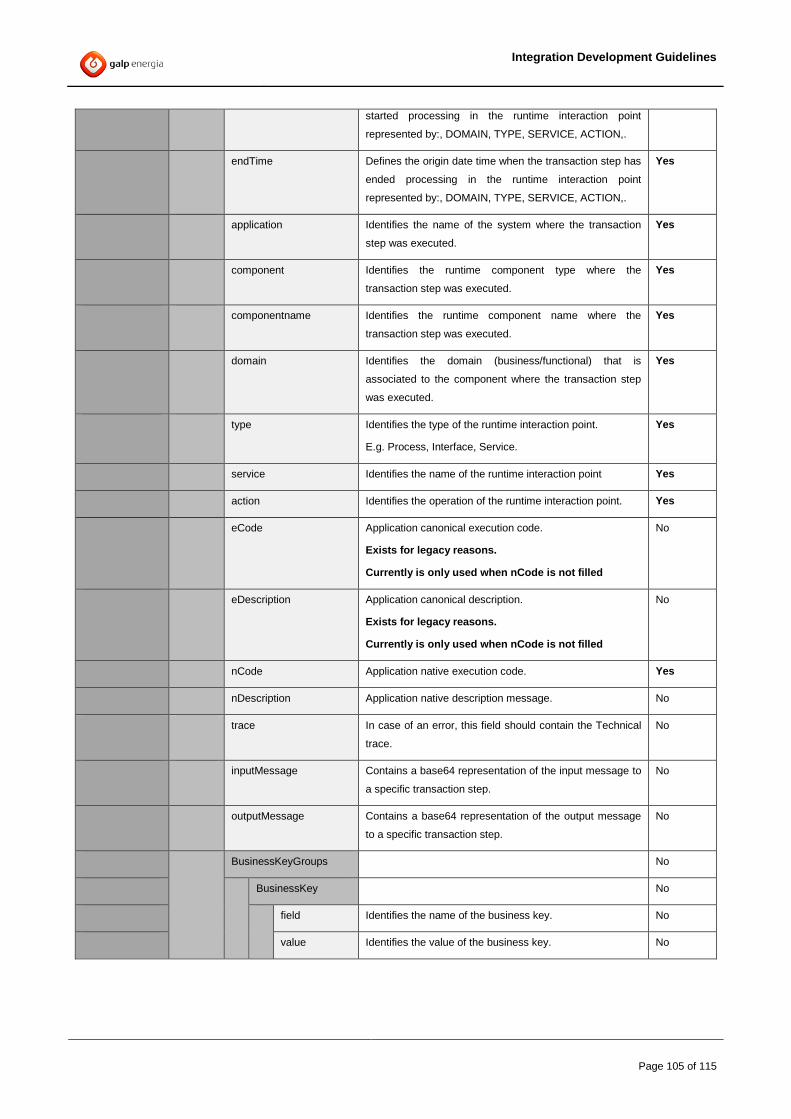
Integration Development Guidelines
Page 105 of 115
started processing in the runtime interaction point
represented by:, DOMAIN, TYPE, SERVICE, ACTION,.
endTime Defines the origin date time when the transaction step has
ended processing in the runtime interaction point
represented by:, DOMAIN, TYPE, SERVICE, ACTION,.
Yes
application Identifies the name of the system where the transaction
step was executed.
Yes
component Identifies the runtime component type where the
transaction step was executed.
Yes
componentname Identifies the runtime component name where the
transaction step was executed.
Yes
domain Identifies the domain (business/functional) that is
associated to the component where the transaction step
was executed.
Yes
type Identifies the type of the runtime interaction point.
E.g. Process, Interface, Service.
Yes
service Identifies the name of the runtime interaction point Yes
action Identifies the operation of the runtime interaction point. Yes
eCode Application canonical execution code.
Exists for legacy reasons.
Currently is only used when nCode is not filled
No
eDescription Application canonical description.
Exists for legacy reasons.
Currently is only used when nCode is not filled
No
nCode Application native execution code. Yes
nDescription Application native description message. No
trace In case of an error, this field should contain the Technical
trace.
No
inputMessage Contains a base64 representation of the input message to
a specific transaction step.
No
outputMessage Contains a base64 representation of the output message
to a specific transaction step.
No
BusinessKeyGroups No
BusinessKey No
field Identifies the name of the business key. No
value Identifies the value of the business key. No

Integration Development Guidelines
Page 106 of 115
Appendix D. HTTP/SOAP Gateway
Note
This appendix describes the HTTP/SOAP Gateway for Framework V2 and Framework V3.
Process Description
The ServiceFramework offers a HTTP/SOAP gateway that exposes all available Services through the
HTTP/SOAP protocol.
This Gateway is an EAR file that can be deployed any number of times where each deploy must have an
unique port.
Points of InterationBackend Applications
Orchestration Domains and Interfaces
EAI Domain
Gateway HTTP/SOAP
httpProtocol
transformationJMS
Deployment Container
Functional Interfaces
JMSConector
Interface
Conector
Interface
ConectorInterface
JMS
Deployment Container
Orichestration Services
JMSOrchestrated
Service
Orchestrated Service
Orchestrated Service
JMS O
EMSEMS
Functional Domains
Deployment Container
Functional Services
Conector
Service
Conector
Service
Conector Service
JMS
http
JMS
TCP
...
Deployment Container
Functional Services
Conector
Service
Conector
Service
Conector
Service
JMS
http
JMS
TCP
...
Deployment Container
Functional Services
Conector
Service
Conector
Service
Conector
Service
JMS
http
JMS
TCP
...
Figure 45 – HTTP/SOAP Gateway.
Overview
The HTTP/SOAP gateway makes processes, services and interfaces (aka: endpoints) available through the
standard HTTP/SOAP protocol.
It works by transforming the incoming message to a JMS/SOAP message to be consumed by any available
endpoint at GALP environment.
The gateway can also be used to retrieve specific system function resources like schemas and wsdls.
Each deployed gateway can be configured to restrict access only to a specific set of endpoints.
Supported methods
The HTTP/SOAP gateway supports two HTTP methods:
GET
o Used to obtain WSIL descriptors, schemas or to generate WSDLs for services.
POST

Integration Development Guidelines
Page 107 of 115
o Used to call a system function (processes, services or interfaces). E.g.
http://localhost:14000/GALP/CORP/Services/Reclamacao/upsert
Other HTTP methods will return a COM-106 Invalid Parameters error.
URI structure
The gateway can be invoked using a specific URI structure. The tokens domain, name, type and action
will be responsible for the gateway to know where the message should be sent internally.
GET
o http://<server>:<port>/inspection.wsil
o http://<server>:<port>/GALP/<domain>/Services/<name>/<action>?wsdl
POST
o System Function Endpoint
http://<server>:<port>/GALP/<domain>/<type>/<name>/<action>
Endpoints
The gateway only allows calling JMS internal endpoints with a specific Queue format.
In order to maintain scalability and ease of use the gateway follows the following rules:
- It doesn’t change the HTTP body message whatsoever. Instead it directly copies the HTTP
body message to the JMS Body Message
- It creates a JMS Header property with the name “soapAction” that contains the value of the
“action” token (that is sent on the URI)
- The queue name is generated dynamically based on the tokens that exist on the URI.
Depending of the type, the queue will have the following format:
Services: GALP.<Domain>.<Service>.<action>.REQ
Interfaces: GALP:<Domain>.INTERFACES.<Service>.<action>.REQ
- The JMS reply will be received by a $TMP queue, and again, the body received will be sent
back via HTTP body to the invoker.
WSIL
Through the URL http://<server>:<port>/inspection?wsil the gateway generates a WSIL descriptor
containing all available services within the TIBCO EAI infrastructure.

Integration Development Guidelines
Page 108 of 115
WSDL links are only available for Services. Processes and Interfaces are enumerated, but no resources are
available for them.
WSDL
Through the service wsdl URL (e.g. http://server:14000/GALP/CORP/Services/Factura/upsert?wsdl), the
gateway generates a WSDL that can be used to call the service.
Restricting the services that are available through the gateway
Each gateway can be configured to only allow access to a specific set of services.
This configuration can be done through the table TIBCAT.T_EAI_GATEWAY_FILTERS.
Column Name Data Type Description
GATEWAY_NAME VARCHAR2 (100 BYTE) Name of the gateway that will load this configuration
SYSTEM_FUNCTION VARCHAR2 (100 BYTE) Name of the service
SYSTEM_FUNCTION_DOMAIN VARCHAR2 (100 BYTE) Domain of the service
SYSTEM_FUNCTION_TYPE VARCHAR2 (100 BYTE) Type of the service
SYSTEM_FUNCTION_OPERATION VARCHAR2 (100 BYTE) Operation of the service
SYSTEM_FUNCTION_VERSION VARCHAR2 (100 BYTE) Version of the service (default 1.0)
INVOKING_SYSTEM_NAME VARCHAR2 (100 BYTE) Name of the system allowed to invoke the service
On startup, the gateway will execute a process to load this configuration to the BW’s memory, using a shared
variable. This process will query the table to get the configuration for a specific gateway, based on a global
variable.
If the query returns no results, the gateway should block all incoming requests.
If the query returns results, only the configured services that are active should be exposed and allowed to go
through the gateway. The configuration fields detailed above will support the use of wildcards, to facilitate the
necessary configuration of the gateway.
As an example, the following scenarios can be achieved:
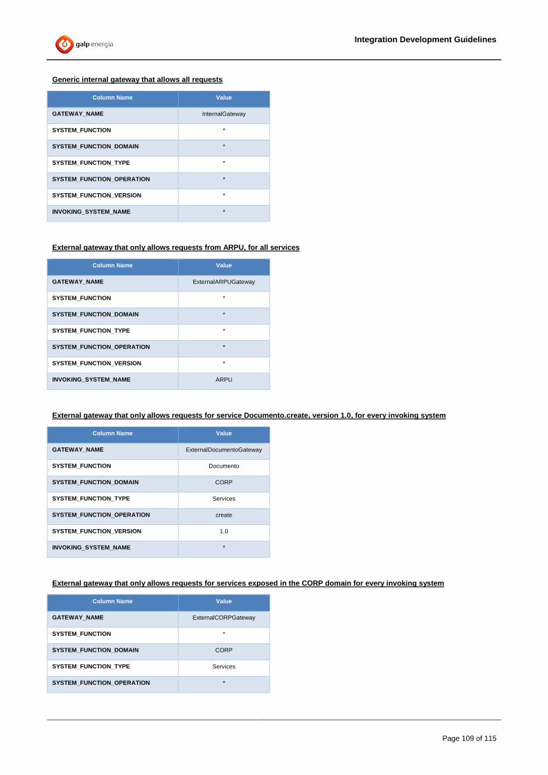
Integration Development Guidelines
Page 109 of 115
Generic internal gateway that allows all requests
Column Name Value
GATEWAY_NAME InternalGateway
SYSTEM_FUNCTION *
SYSTEM_FUNCTION_DOMAIN *
SYSTEM_FUNCTION_TYPE *
SYSTEM_FUNCTION_OPERATION *
SYSTEM_FUNCTION_VERSION *
INVOKING_SYSTEM_NAME *
External gateway that only allows requests from ARPU, for all services
Column Name Value
GATEWAY_NAME ExternalARPUGateway
SYSTEM_FUNCTION *
SYSTEM_FUNCTION_DOMAIN *
SYSTEM_FUNCTION_TYPE *
SYSTEM_FUNCTION_OPERATION *
SYSTEM_FUNCTION_VERSION *
INVOKING_SYSTEM_NAME ARPU
External gateway that only allows requests for service Documento.create, version 1.0, for every invoking system
Column Name Value
GATEWAY_NAME ExternalDocumentoGateway
SYSTEM_FUNCTION Documento
SYSTEM_FUNCTION_DOMAIN CORP
SYSTEM_FUNCTION_TYPE Services
SYSTEM_FUNCTION_OPERATION create
SYSTEM_FUNCTION_VERSION 1.0
INVOKING_SYSTEM_NAME *
External gateway that only allows requests for services exposed in the CORP domain for every invoking system
Column Name Value
GATEWAY_NAME ExternalCORPGateway
SYSTEM_FUNCTION *
SYSTEM_FUNCTION_DOMAIN CORP
SYSTEM_FUNCTION_TYPE Services
SYSTEM_FUNCTION_OPERATION *
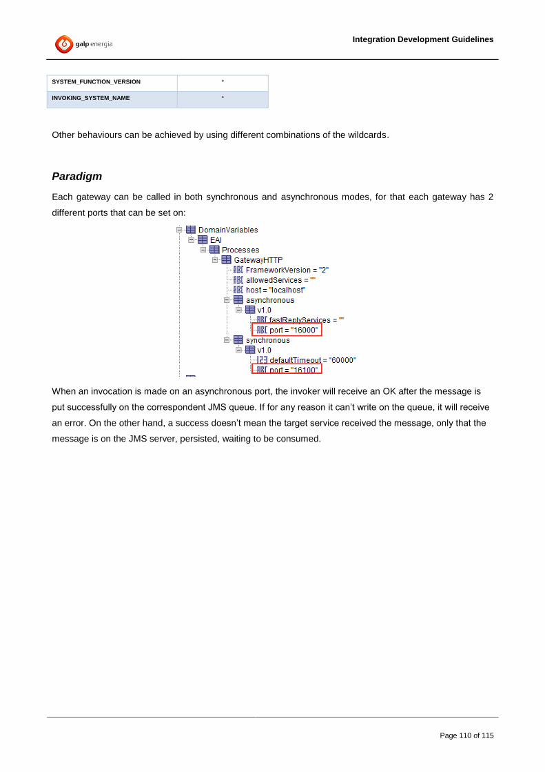
Integration Development Guidelines
Page 110 of 115
SYSTEM_FUNCTION_VERSION *
INVOKING_SYSTEM_NAME *
Other behaviours can be achieved by using different combinations of the wildcards.
Paradigm
Each gateway can be called in both synchronous and asynchronous modes, for that each gateway has 2
different ports that can be set on:
When an invocation is made on an asynchronous port, the invoker will receive an OK after the message is
put successfully on the correspondent JMS queue. If for any reason it can’t write on the queue, it will receive
an error. On the other hand, a success doesn’t mean the target service received the message, only that the
message is on the JMS server, persisted, waiting to be consumed.
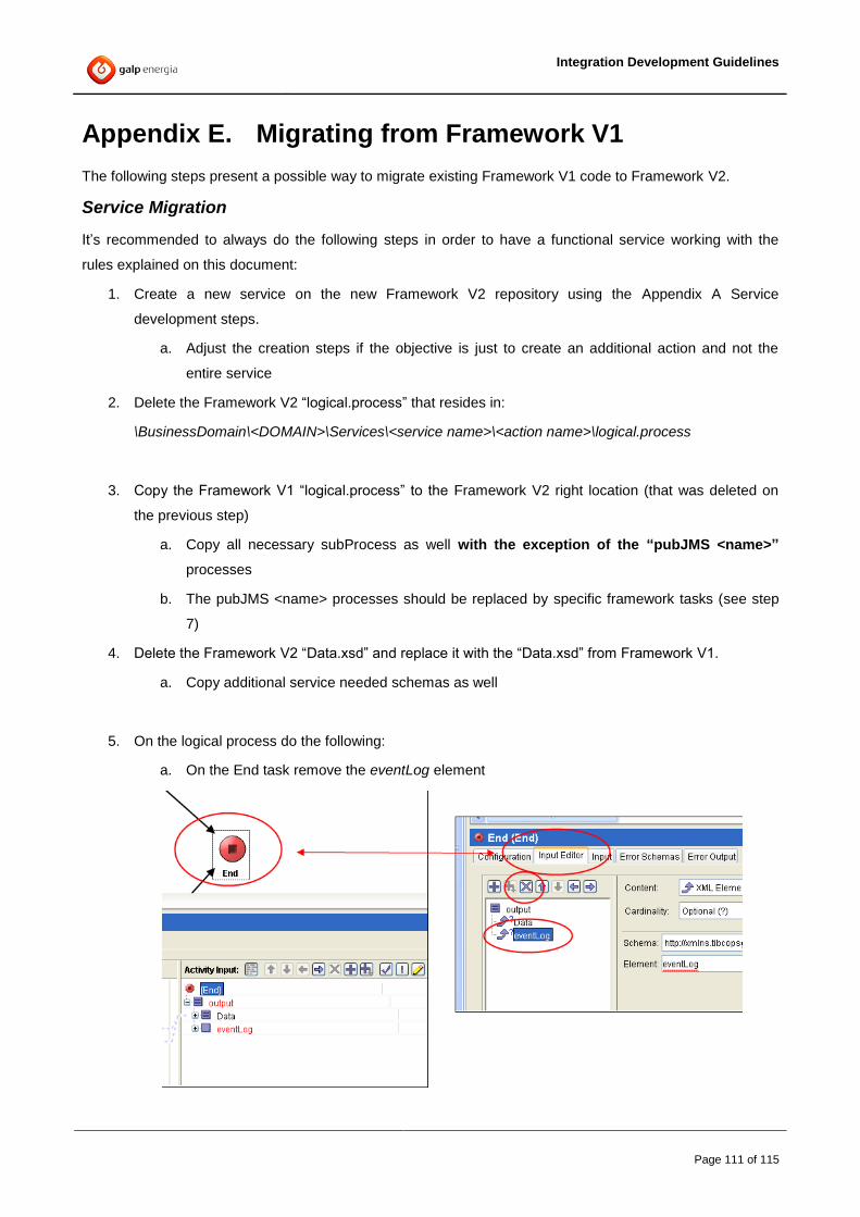
Integration Development Guidelines
Page 111 of 115
Appendix E. Migrating from Framework V1
The following steps present a possible way to migrate existing Framework V1 code to Framework V2.
Service Migration
It’s recommended to always do the following steps in order to have a functional service working with the
rules explained on this document:
1. Create a new service on the new Framework V2 repository using the Appendix A Service
development steps.
a. Adjust the creation steps if the objective is just to create an additional action and not the
entire service
2. Delete the Framework V2 “logical.process” that resides in:
\BusinessDomain\<DOMAIN>\Services\<service name>\<action name>\logical.process
3. Copy the Framework V1 “logical.process” to the Framework V2 right location (that was deleted on
the previous step)
a. Copy all necessary subProcess as well with the exception of the “pubJMS <name>”
processes
b. The pubJMS <name> processes should be replaced by specific framework tasks (see step
7)
4. Delete the Framework V2 “Data.xsd” and replace it with the “Data.xsd” from Framework V1.
a. Copy additional service needed schemas as well
5. On the logical process do the following:
a. On the End task remove the eventLog element

Integration Development Guidelines
Page 112 of 115
Figure 46 – removing eventLog on the End Task.
6. Replace all existing Mappers and Assign tasks that reference Business Keys with the Framework
“BusinessKeys” task
Figure 47 – BusinessKeys framework task
7. The “writeKeys” and “getDynamicDestinations” and “pubJMS <name>” tasks that are used on V1 are
deprecated and must be replaced by one of the following:
a. “routeAndForward single task” (recommended to use whenever possible)
b. The “routeEvent” and “Forward” specific tasks (to use only when the above is not possible)
8. Remove all “catch” processes on the logical that are not necessary for specific Business needs. The
framework main process should catch all exceptions including timeouts.
9. Remove all “writeLog Processes” and checkError Processes
The example on the right shows a
Framework V1 process that was migrated
to V2.
The Mapper “[Map Data] Keys” was
replaced with the “BusinessKeys”
framework task.
The routing code on the Framework V1
that used the now deprecated “writeKeys”
and “get Dynamic Destinations” can be
replaced by the “RoutingEvent” while the
specific “pubJMS <domain>” processes
that pushed the message to the next
domain can be replaced by the “forward
message”. As such the “Route and
Forward” were used.
Finally the writeLog and catch (all) are
removed.
Rep
lac
e
with

Integration Development Guidelines
Page 113 of 115
Interface Migration
Framework V2 interfaces should always receive and send XML string has the body data. The following rules
should be followed:
1. Create a new interface on the new Framework V2 repository using the Appendix A Service
development steps, while adjusting the type to “Interfaces” whenever is needed. An example
interface can be seen on the repo.TEMPLATE.
a. When using JMS queues, the destination should use the new V2 Format as explained on
4.13.3 Subject Rules.
2. Delete the Framework V2 “logical.process” that resides in:
\BusinessDomain\<DOMAIN>\Interfaces\<Interface name>\<action name>\logical.process
3. Copy the Framework V1 “logical.process” to the Framework V2 right location (that was deleted on
the previous step)
a. Copy all necessary subProcess as well.
4. VERY IMPORTANT: If there is interface logic on the starter process that logic must be moved to the
“logical.process”
In these cases the logical process must be adapted in order to assure that the Interface functionality
is maintained.
5. Replace all existing Mappers and Assign tasks that reference Business Keys with the Framework
“BusinessKeys” task. If a Business Keys task doesn’t exist then it needs to be created.
Figure 48 – BusinessKeys framework task
6. After parsing the incoming XML message string, the header should be re-initialized with the specific
framework Task
a. There is a generic one on “framework resources” and, depending on the system it might
exist a specific one (eg: “Re-init SAP-PI header” task exists on the ERP domain)

Integration Development Guidelines
Page 114 of 115
7. The “writeKeys” and “getDynamicSources” and “pubJMS <name>” tasks that are used on V1 are
deprecated and must be replaced by the “discoverSourceApplication” framework task
Figure 49 – Discover Source Application framework task
8. Any “pubJMS <name>” tasks that are used on V1 are deprecated and must be replaced by the
“forward Message” framework task
Figure 50 – Forward Message framework task
9. On the logical process do the following:
a. On the End task remove the eventLog element
Figure 51 – removing eventLog on the End Task.
10. On “Synchronous Interfaces” only, the Starter Task can be updated to include a parser XML to
return the message back to the source system.
If this solution was followed, the render of this parser had to be done on the logical, right before the
end-task

Integration Development Guidelines
Page 115 of 115
Process Migration
Framework V2 processes reside under the BusinessDomain/<DOMAIN>/Processes directory and as such,
any V1 process must firstly be moved to this new location.
Additionally, any “Process” type should be adapted to follow the same directory structure as explained on 3.3
BW Project Structure
Common steps
The migrated services, Interfaces and processes will probably need specific configuration on:
Error Translation as explained on 4.3.6.3 Native Execution Codes Translation. Without the new
entries the invocation will never finish with a success
Main Configuration as explained on 4.10.1 Service Catalog in order to set the SLA time, the system
where the service is running and the default Application it connects to.
On the Framework V1, whenever a service, Interface or Process needed to call an existing TIBCO
Functional or Corporate Service synchronously it was used the SOAP request reply activity on the logical
process and the target wsdl was put on the:
/BusinessDomain/<DOMAIN>/BusinessResources/WSDL/TargetDomains,
On the Framework V2, According to the rules defined on 3.4.3 Internal Service Call, the usage of
SOAP/Request Reply to call Internal TIBCO services is forbidden.
To invoke a target TIBCO Service the Destination ServiceSchema DTL must be imported on this repository
and the iCall of the imported service should be always used.
For more information about the ServiceSchema DTL check the Appendix B-Creating a Service Schema DTL