integrating personnel movement simulation into preliminary ship ...

1
2© 2017 The MathWorks, Inc.
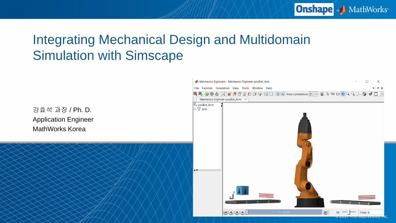
Integrating Mechanical Design and Multidomain
Simulation with Simscape
강효석과장 / Ph. D.
Application Engineer
MathWorks Korea
3
In this session
Onshape and MATLAB enable
engineers to combine CAD models
with multidomain, dynamic simulation
MATLAB

4
In this session
Onshape and MATLAB enable
engineers to combine CAD models
with multidomain, dynamic simulation
MATLAB Simulink
StateflowSimscape
Computer
Vision
Real-Time
Testing
Image
Processing
Statistics &
Optimization
Control
Systems
Signal
Processing
Machine
Learning
5
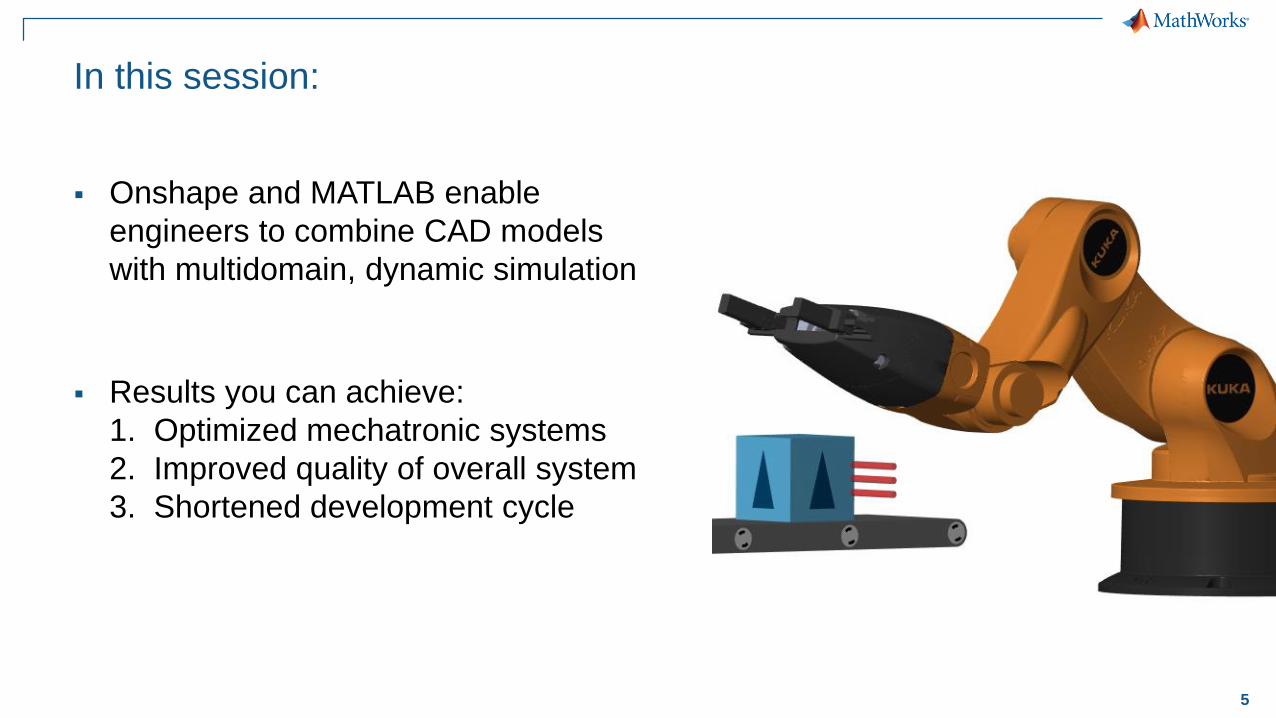
In this session:
Onshape and MATLAB enable
engineers to combine CAD models
with multidomain, dynamic simulation
Results you can achieve:
1. Optimized mechatronic systems
2. Improved quality of overall system
3. Shortened development cycle

6
Why Combine CAD and
Multidomain, Dynamic Simulation?
Fewer iterations on mechanical design
because requirements are refined
Fewer mechanical prototypes
because mistakes are caught earlier
Reduced system cost
because components are not oversized
Less system downtime
because system is debugged
using virtual commissioning
7
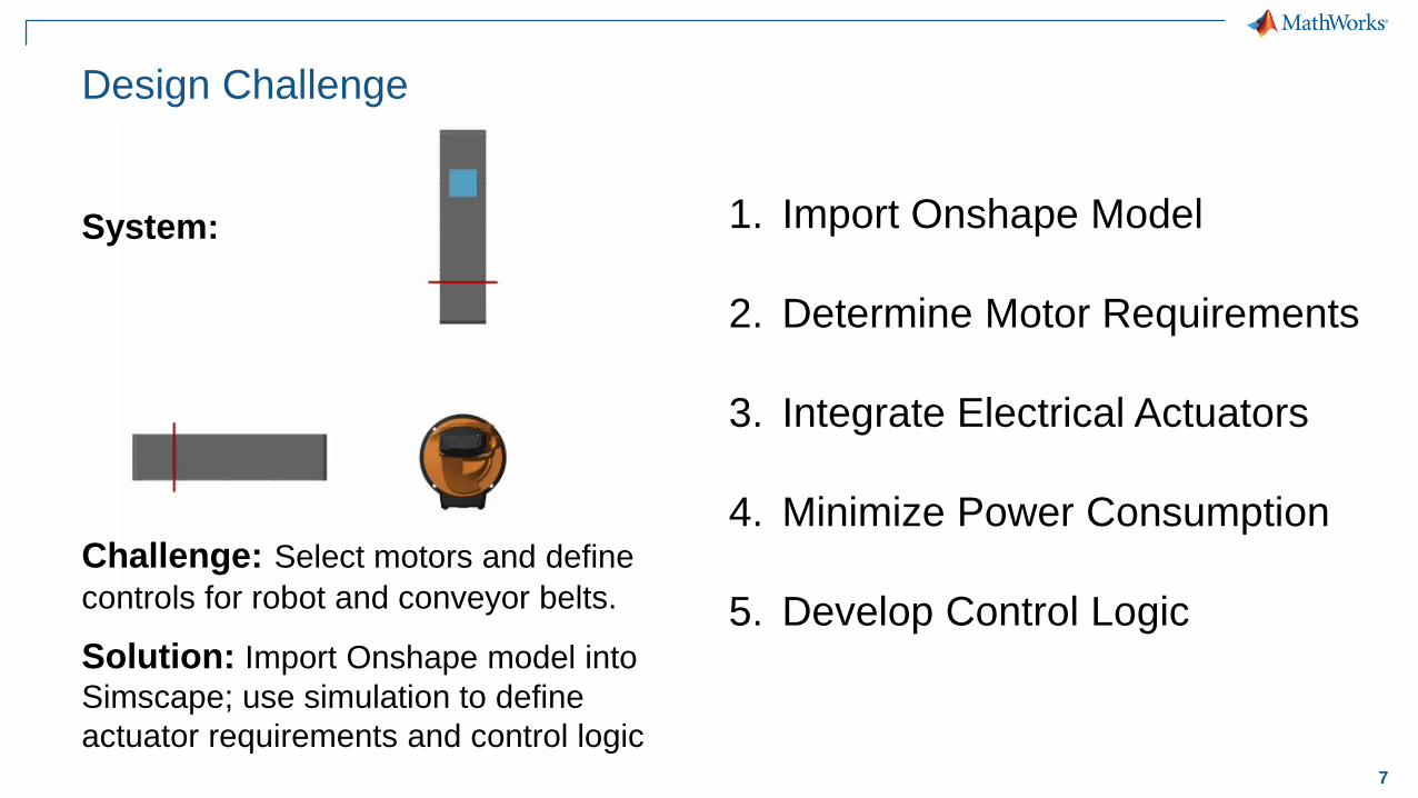
Design Challenge
Challenge: Select motors and define
controls for robot and conveyor belts.
Solution: Import Onshape model into
Simscape; use simulation to define
actuator requirements and control logic
System: 1. Import Onshape Model
2. Determine Motor Requirements
3. Integrate Electrical Actuators
4. Minimize Power Consumption
5. Develop Control Logic
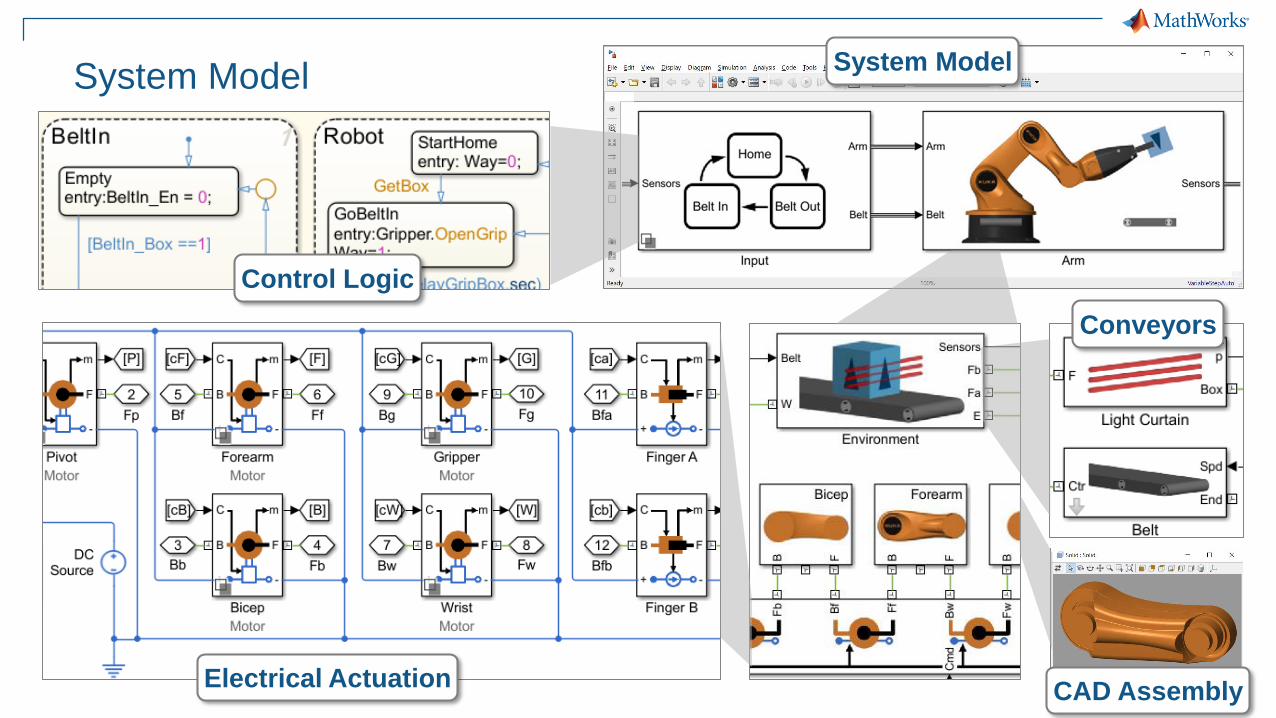
8
System ModelSystem Model
Control Logic
Electrical Actuation
Conveyors
CAD Assembly
9
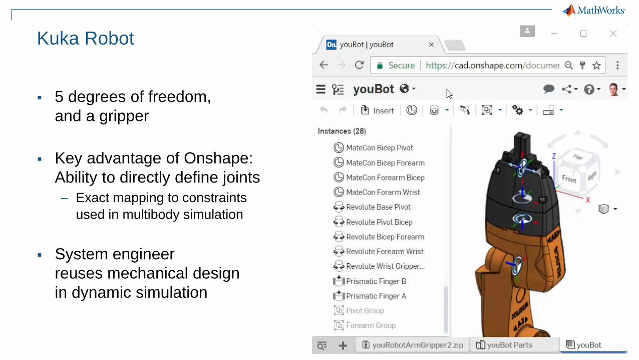
Kuka Robot
5 degrees of freedom,
and a gripper
Key advantage of Onshape:
Ability to directly define joints
– Exact mapping to constraints
used in multibody simulation
System engineer
reuses mechanical design
in dynamic simulation

10
1. Import Model from Onshape
Convert CAD assembly to
dynamic simulation model
for use within Simulink
– Mass, inertia, geometry, and joints
11
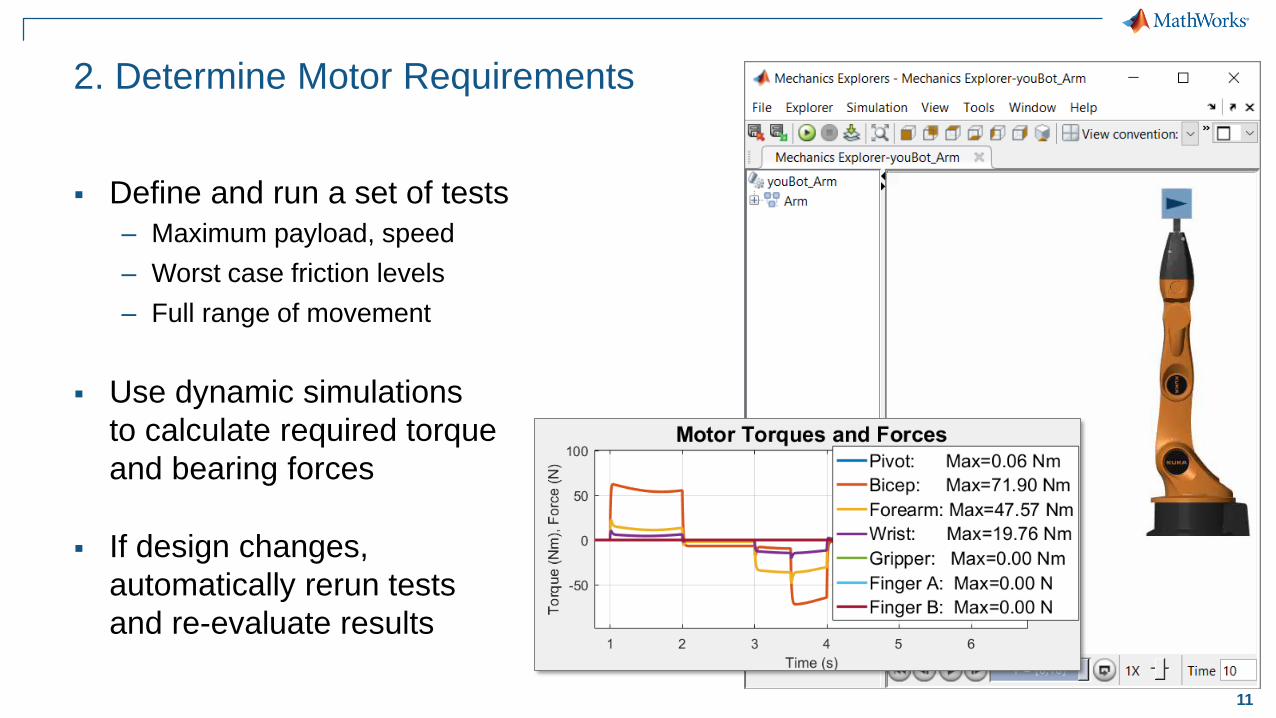
2. Determine Motor Requirements
Define and run a set of tests
– Maximum payload, speed
– Worst case friction levels
– Full range of movement
Use dynamic simulations
to calculate required torque
and bearing forces
If design changes,
automatically rerun tests
and re-evaluate results

12
3. Integrate Electrical Actuators
Add motors, drive circuitry,
gears, and friction
Choose motors based on
torque requirements
Assign parameters
directly from data sheets
13
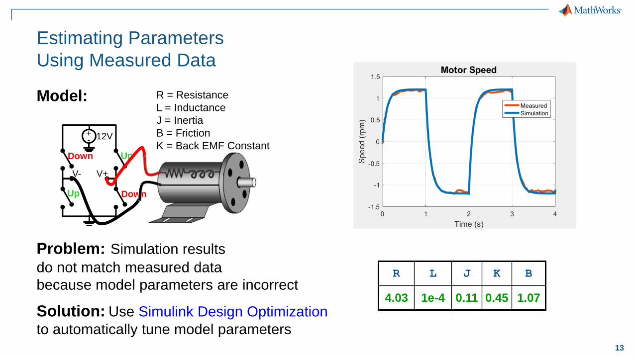
Estimating Parameters
Using Measured Data
Problem: Simulation results
do not match measured data
because model parameters are incorrect
Solution: Use Simulink Design Optimization
to automatically tune model parameters
Model:
+- 12V
Up
Up Down
Down
V+V-
R = Resistance
L = Inductance
J = Inertia
B = Friction
K = Back EMF Constant
R L J K B
3 0.01 0.01 0.02 0.5
R L J K B
4.03 1e-4 0.11 0.45 1.07
14
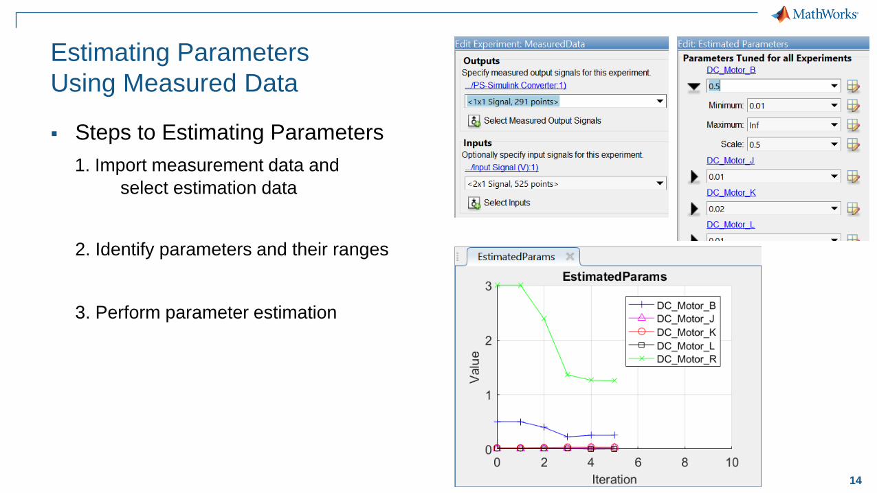
Estimating Parameters
Using Measured Data
Steps to Estimating Parameters
1. Import measurement data and
select estimation data
2. Identify parameters and their ranges
3. Perform parameter estimation

15
4. Minimize Power Consumption
Challenge: Identify arm trajectory that
minimizes power consumption.
Solution: Use dynamic simulation to
calculate power consumption, and use
optimization algorithms to tune trajectory.
Model:
16
…Computer Cluster
Workers
… …
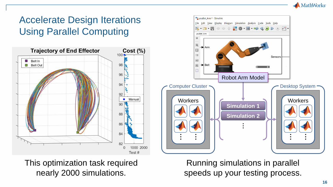
Running simulations in parallel
speeds up your testing process.
Desktop System
Workers
… …
Simulation 1
Simulation 2
Accelerate Design Iterations
Using Parallel Computing
Robot Arm Model
This optimization task required
nearly 2000 simulations.

17
5. Design Control Logic for
Arm and Conveyor Belts
Sense quantities
within model that
govern system events
Design logic
using a state chart
Use outputs of logic
to control models
of system components
Belt Empty
Belt On
Box Waiting
Box on Belt?
Light blocked?
Curtain clear?
Control Logic

18
Home
5. Design Control Logic for
Arm and Conveyor Belts
Belt
In
Belt
Out
Closed Grip
Open
State charts depend
on each other
19
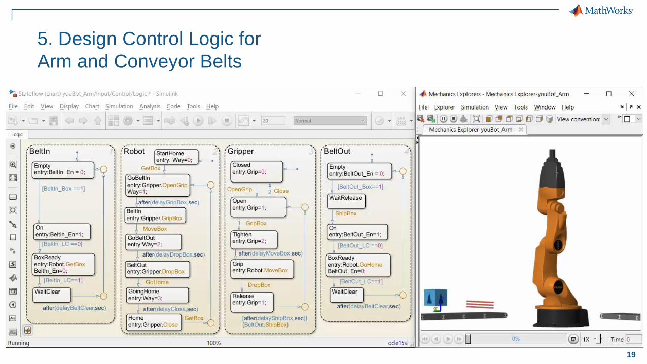
5. Design Control Logic for
Arm and Conveyor Belts
Parallel state charts for
system-level logic
– Logic for arm depends upon
state of conveyor belt
Define algorithm with flow charts,
state transition diagrams, truth tables,
and state transition tables
Animation to observe behavior
and debug algorithm
20
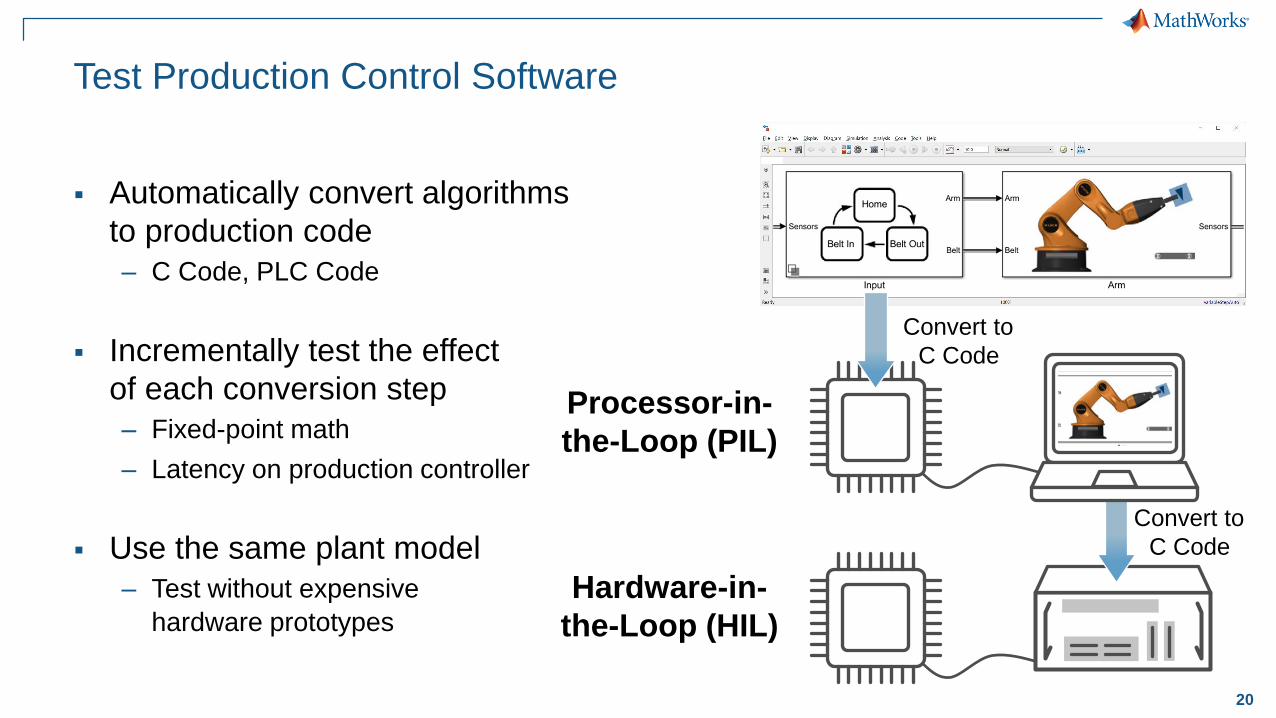
Test Production Control Software
Automatically convert algorithms
to production code
– C Code, PLC Code
Incrementally test the effect
of each conversion step
– Fixed-point math
– Latency on production controller
Use the same plant model
– Test without expensive
hardware prototypes
Hardware-in-
the-Loop (HIL)
Processor-in-
the-Loop (PIL)
Convert to
C Code
Convert to
C Code
21
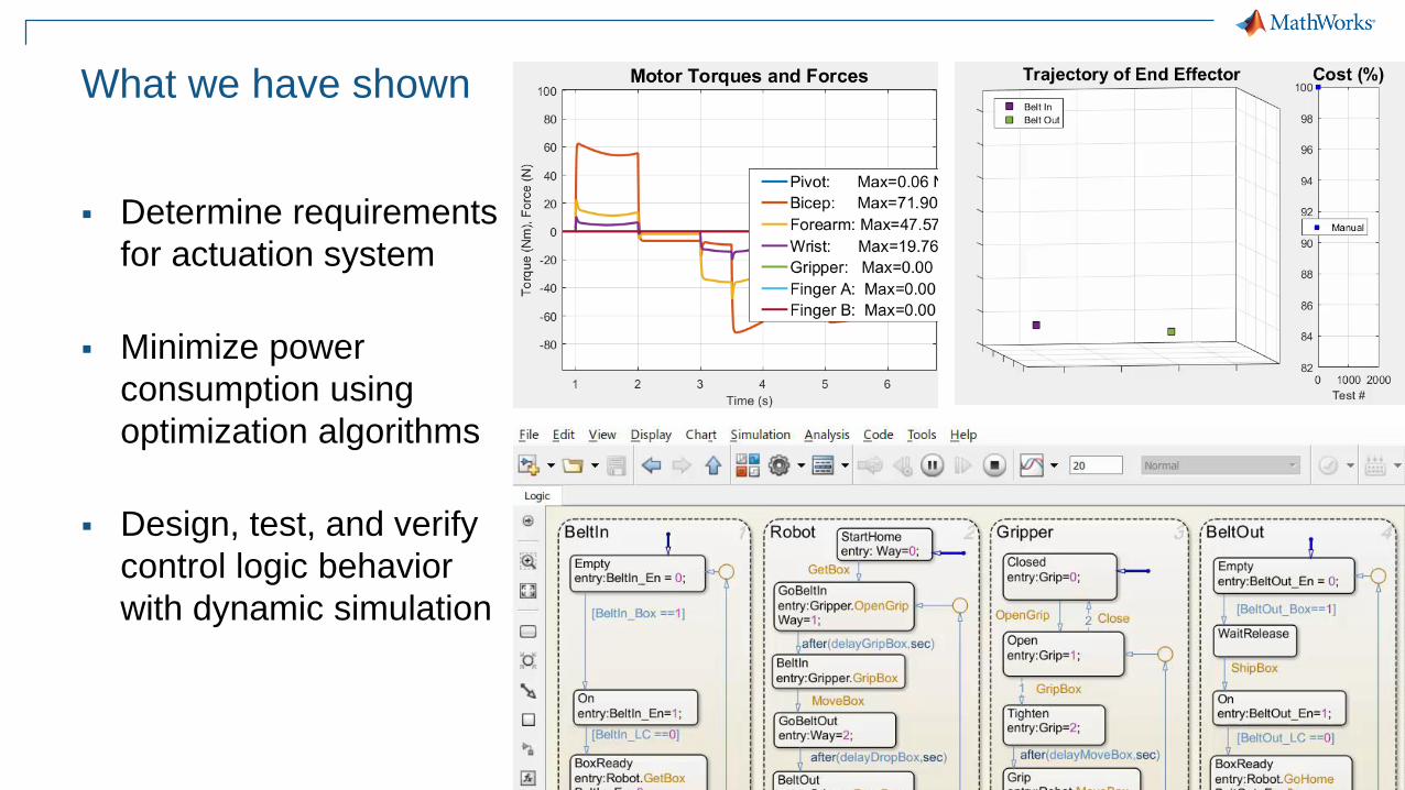
What we have shown
Determine requirements
for actuation system
Minimize power
consumption using
optimization algorithms
Design, test, and verify
control logic behavior
with dynamic simulation
22
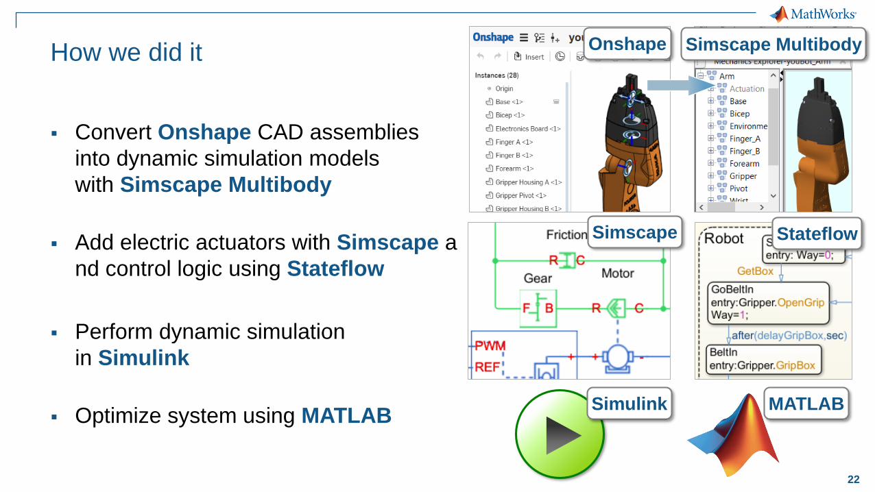
How we did it
Convert Onshape CAD assemblies
into dynamic simulation models
with Simscape Multibody
Add electric actuators with Simscape a
nd control logic using Stateflow
Perform dynamic simulation
in Simulink
Optimize system using MATLAB
Simscape Multibody
Simscape Stateflow
Onshape
Simulink MATLAB
23
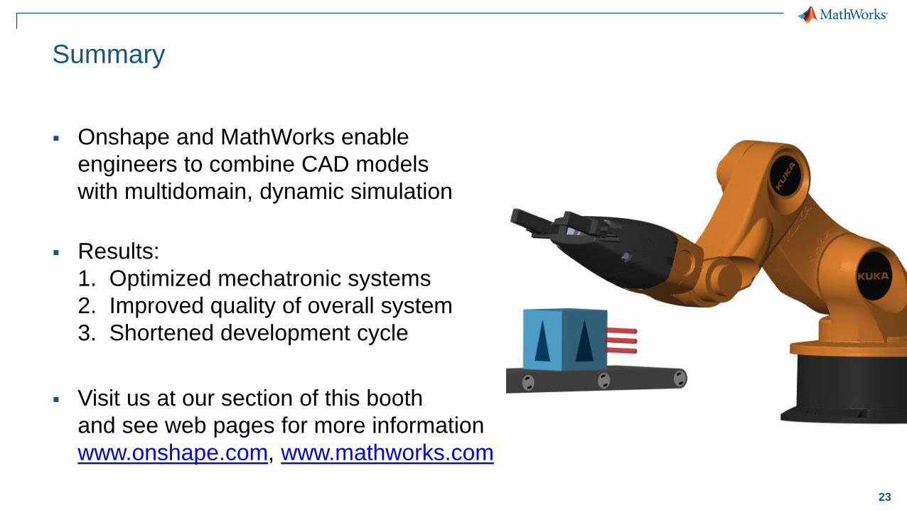
Summary
Onshape and MathWorks enable
engineers to combine CAD models
with multidomain, dynamic simulation
Results:
1. Optimized mechatronic systems
2. Improved quality of overall system
3. Shortened development cycle
Visit us at our section of this booth
and see web pages for more information
www.onshape.com, www.mathworks.com