INTEGRATED MICROWAVE BANDPASS AND BANDSTOP …eprints.utem.edu.my/18428/1/Integrated Microwave...
24
INTEGRATED MICROWAVE BANDPASS AND BANDSTOP FILTER TO MULTIFUNCTION OPERATION IN WIRELESS COMMUNICATION SYSTEM NURUL FAMYZA BINTI ARHAM This Report Is Submitted in Partial Fulfilment of Requirements For The Bachelor Degree of Electronic Engineering (Telecommunications Electronics) With Honours Faculty of Electronics and Computer Engineering Universiti Teknikal Malaysia Melaka June 2016
Transcript of INTEGRATED MICROWAVE BANDPASS AND BANDSTOP …eprints.utem.edu.my/18428/1/Integrated Microwave...

i
INTEGRATED MICROWAVE BANDPASS AND BANDSTOP FILTER TO
MULTIFUNCTION OPERATION IN WIRELESS COMMUNICATION
SYSTEM
NURUL FAMYZA BINTI ARHAM
This Report Is Submitted in Partial Fulfilment of Requirements For The
Bachelor Degree of Electronic Engineering (Telecommunications Electronics)
With Honours
Faculty of Electronics and Computer Engineering
Universiti Teknikal Malaysia Melaka
June 2016
ii

iii
DECLARATION
“I hereby declare that the work in this project is my own except for summaries and quotations which have been duly acknowledge.”
iv
APPROVAL
“I acknowledge that I have read this report and in my opinion this report is sufficient in term of scope and quality for the award of Bachelor of Electronic Engineering (Industrial Electronics/ Computer Engineering/ Electronic Telecommunication/
Wireless Communication)* with Honours.”

v
DEDICATION
Special dedication to my beloved parents,
Arham bin Wasimin & Hafizah binti Aris
To my backbone
Mohd Fadhil Jamaludin
Mohd Nazrul Nizam
Nazatul Asyikin
To my supervisor
PM. Dr. Zahriladha bin Zakaria
My friends and my fellow lecturers
Thank you for all your care, support, guidance, and believe in me.

vi
ACKNOWLEDGMENT
First and the most important person that help me for the whole this two
semester PM. DR. Zahriladha bin Zakaria. Thank you for your guidance help me to
understand about this project. His guidance from the beginning to make me
understand about the project until the completion of this thesis. Thank you for
spending your valuable time to keep me on track while completing my project.
I also would like to give the appreciation to the Dean’s of faculty of
Electronic and Computer Engineering and also the lecturers who contribute during
the seminar thesis writing. Dr. Kok Swee Leong, the coordinator of PSM programme
for his inestimable and invaluable guidance. Thanks so much for taking time from
your busy schedule to give an introduction about this PSM program and provided the
sources of the courses.
I am thankful to technician PSM Lab, Encik Imran Bin Mohamed Ali and
technician Makmal Penyelidikan I, Encik Mohd Sufian Bin Abu Talib for helping me
during the fabrication and measurement process.
Thank you to all my friends who supported and help me during this final year
project.

vii
ABSTRACT
Ultra Wideband bandpass (UWB) filter provide a lot of advantage such as
low power and high data precision. However, UWB bandpass filter easy to get the
interference from the other radio frequency spectrum such as C-band satellite
communication system 4GHz, radar system 10GHz, and X-band satellite
communication 8.4GHz and radar system 10GHz. This project is to design the UWB
bandpass filter integrated with Defected Microstrip Structure (DMS). Function of the
DMS is to act as notched response. The pin diode added to act as tuning the notch
response. The substrate used is Roger 4350B with thickness 0.508mm, dielectric
constant 3.48 and loss tangent 0.0019. The tool for the measurement after the
fabrication process is by using the Vector Network Analyser (VNA). The return loss
must be better than 15 dB and the insertion loss around 0.1dB. When the pin diode
on the notched response occur at 6.7GHz while when the pin diode off the notched
response occur at 6.6GHz and 9.8GHz.

viii
ABSTRAK
Ultra luas jalur penapis laluan jalur (UWB) penapis memberikan banyak
kelebihan seperti tenaga yang rendah dan ketepatan data yang tinggi. Walau
bagaimanapun, UWB penapis laluan jalur mudah untuk mendapat gangguan dari
spektrum frekuensi radio yang lain seperti sistem komunikasi satelit C-band 4GHz,
sistem radar 10GHz, dan X-band komunikasi satelit 8.4GHz dan sistem radar
10GHz. Projek ini adalah untuk mereka bentuk penapis UWB laluan jalur bersepadu
dengan jalur tinggi bersepadu bersama dengan struktur mikro-strip (DMS). Fungsi
DMS adalah untuk bertindak sebagai tindak balas bertakuk. Pin diod ditambah
untukbertindak sebagai penalaan sambutan takuk. Substrat yang digunakan adalah
Roger 4350B dengan ketebalan 0.508mm, pemalar dielektrik 3.48 dan kehilangan
tangen 0.0019. Alat untuk mengukur selepas proses fabrikasi adalah dengan
menggunakan Vector Network Analyser (VNA). Kehilangan pulangan mestilah lebih
baik daripada 15 dB dan kehilangan sisipan sekitar 0.1dB. Apabila diod pin dibuka
kepada sambutan bertakuk berlaku pada 6.7GHz manakala apabila diod pin ditutup
sambutan bertakuk berlaku pada 6.6GHz dan 9.8GHz.

ix
TABLE OF CONTENT
CHAPTER CONTENT PAGES
TITLE i
CONFIRMATION FORM ii
DECLARATION iii
APPROVAL iv
DEDICATION v
ACKNOWLEDGMENT vi
ABSTRACT vii
ABSTRAK viii
TABLE OF CONTENT ix
LIST OF TABLES xii
LIST OF FIGURES xiii
LIST OF ABBREVIATIONS xv
LIST OF APPENDICES xvi
I INTRODUCTION
1.1 Introduction 1
1.2 Problem Statement 2
1.3 Objectives 2
1.4 Scope of Work 3
1.5 Chapter Review 3
x
II LITERITURE REVIEW
2.1 Ultra –wideband (UWB) 5
2.1.1 UWB RF systems and applications 6
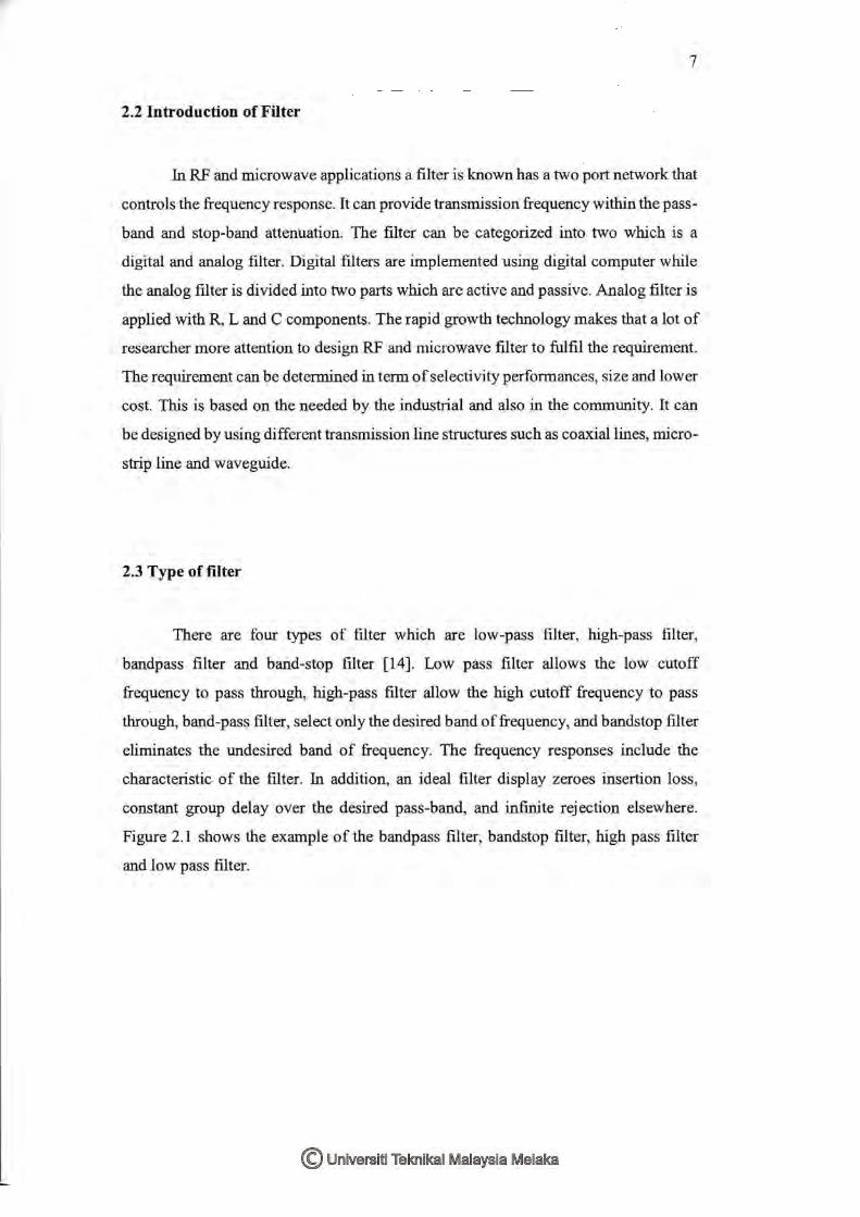
2.2 Introduction of filter 7
2.3 Type of filter 7
2.4 Microstrip 8
2.5 Notch Response 9
2.5.1 Defected Microstrip Structure 10
2.6 Related research 11
III METHODOLOY
3.1 Methodology 16
3.2 Design UWB tunable bandpass filter 18
3.2.1 Filter specification 20
3.2.2 Calculation of UWB bandpass filter 21
3.2.3 UWB transmission line schematic 24
3.2.4 UWB microstrip line shematic 24
3.2.5 UWB Microstrip Schematic with T-junction 26
and Via-ground
3.2.6 Layout structure 26
3.3 Defected Microstrip Structure (DMS) 27
3.4 UWB bandpass filter with Defected Microstrip structure 27
3.5 Fabrication and measurement 28
IV RESULT AND DISCUSSION
4.1 Transmission line schematic of UWB bandpass filter 29
4.2 Microstrip line schematic of UWB bandpass filter 31
4.3 Microstrip line schematic UWB bandpass filter 32
with T junction and Via ground.
4.3.1 Microstrip line schematic UWB bandpass 32
filter with T junction and via ground (before tuning).
xi
4.3.2 Microstrip line schematic UWB bandpass filter 34
with T junction and via ground (after tuning).
4.4 Layout structure of UWB bandpass filter 36
4.5 Defected Microstrip Structure (DMS) 38
4.6 UWB bandpass filter integrated with DMS 41
4.7 UWB bandpass filter integrated with DMS (fabrication) 42
V CONCLUSION AND FUTURE WORK
5.1 Conclusion 45
5.2 Future Work 48
REFERENCES 49
APPENDICES 52

xii
LIST OF TABLE
TABLE TITLE PAGES
3.1 Specification of bandpass filter design 20
3.2 Properties of substrate Roger Duroid 4350B 20
3.3 Specification for number of order 21
3.4 Element Values of UWB Transmission Filter with 22
Short-Circuited Stub with Pass-band Ripple 0.1dB
.....3.5 Value of the characteristic admittances. 23
3.6 Value of the characteristic impedances 23
3.7 Value of width and length after ‘line-clac’ 24
4.1 Value of width and length after the tuning process. 34
4.2 Value of the layout structure after the tuning process 37

xiii
LIST OF FIGURE
FIGURE TITLE PAGES
2.1 Low Pass, High Pass, Band-pass and Band-stop Filter. 8
2.2 Micro-strip Structure 9
2.3 Band-pass Filter with Notch Response 9
2.4 Defected Micro-strip Structure 10
3.1 Flow chart of the overall project 18
3.2 Flow chart of the overall project 19
3.3 Transmission line schematic 24
3.4 ‘Line-Calc’ in ADS software 25
3.5 Microstrip line schematic 25
3.6 UWB Micro-strip Schematic with T-junction and 26
Via-ground
3.7 Picture of layout structure of UWB bandpass filter. 26
3.8 Type of the defected microstrip structure 27
3.9 Layout structure UWB bandpass filter with DMS. 27
4.1 Transmission line schematic of UWB bandpass filter. 30
4.2 Simulation result of transmission line schematic of 30
UWB bandpass filter.
4.3 Microstrip line schematic UWB bandpass filter 31
4.4 Simulation result of microstrip line schematic UWB 31
bandpass filter.
4.5 Microstrip line schematic with T junction and Via 33
ground (before tuning).
.....4.6 Simulation result of Microstrip line schematic with T 33
junction and Via ground (before tuning).
4.7 Mictcrosrip line schematic with T junction and 35
Via ground (after tuning)
xiv
4.8 Simulation result of Mictcrosrip line schematic with T 35
junction and Via ground (after tuning)
4.9 Layout structure of UWB from the microstrip line 36
4.10 Simulation result of layout structure of UWB from the 37
microstrip line.
4.11 Layout structure after the tuning process 37
4.12 Simulation result of the layout structure after the tuning 38
Process
4.13 T shaped of the defected microstrip structure. 38
4.14 Simulation result of T-shaped 39
4.15 H-shaped defected microstrip structure 39
4.16 Simulation result of the DMS 39
4.17 Square shaped DMS 40
4.18 Simulation result of square shaped 40
4.19 Square shaped DMS when pin diode off. 40
4.20 Simulation result of square shaped when pin diode off. 41
4.21 UWB integrated with DMS 41
4.22 Simulation result of UWB integrated with notched response 42
4.23 UWB integrated with DMS when pin diode off 42
4.24 Simulation result of UWB integrated with DMS when 42
pin diode off
4.25 Measurement result of UWB with DMS when pin diode on 43
4.26 Measurement result of UWB with DMS when pin diode off 44

xv
LIST OF ABBREVIATION
UWB - Ultra wide-band
BPF - Band-pass filter
DMS - Defected Microstrip Structure
DGS - Defected Ground Structure
ADS - Advance Design System
RF - Radio Frequency
FCC - Federal Communication Commission
MMR - Multimode Resonator
WLAN - Wireless Local Area Network
DSLR - Dual Stub Loaded Resonator
VNA - Vector Network Analyzer
SIR - Step Impeadance Resonator

xvi
LIST OF APPENDICES
APPENDIX TITLE PAGES
A INOTEK EXHIBITION 2016 POSTER 52
B FABRICATION PROCESS 53

iv


![IEEE MICROWAVE AND WIRELESS COMPONENTS ...arXiv:1805.03783v1 [eess.SP] 10 May 2018 IEEE MICROWAVE AND WIRELESS COMPONENTS LETTERS 1 Continuously Tunable Dual-mode Bandstop Filter Amir](https://static.fdocuments.in/doc/165x107/5e7375897f5291376d3d7de2/ieee-microwave-and-wireless-components-arxiv180503783v1-eesssp-10-may-2018.jpg)