Design of Combline Bandpass Filters - E-Doodles · Combline Bandpass Filters Interdigital BPF...
32
Design of Combline Bandpass Filters Interdigital BPF included
Transcript of Design of Combline Bandpass Filters - E-Doodles · Combline Bandpass Filters Interdigital BPF...

Design of Combline Bandpass Filters
Interdigital BPF included

Microwave & Millimeter-wave Lab.
Comline Bandpass Filters
2
Input Output
Typical Combline Bandpass Filter

Microwave & Millimeter-wave Lab.
Equivalent circuit
3
J12 J23 J34
GA
b1 b3Yin
a
J01
b2
GB
Input coupling
Output coupling

Microwave & Millimeter-wave Lab.
Coupled section
equivalent circuit
4
Y2 , l
Y1 , l
Y3 , l
Zoe, Zoo
Microwave & Millimeter-wave Lab.
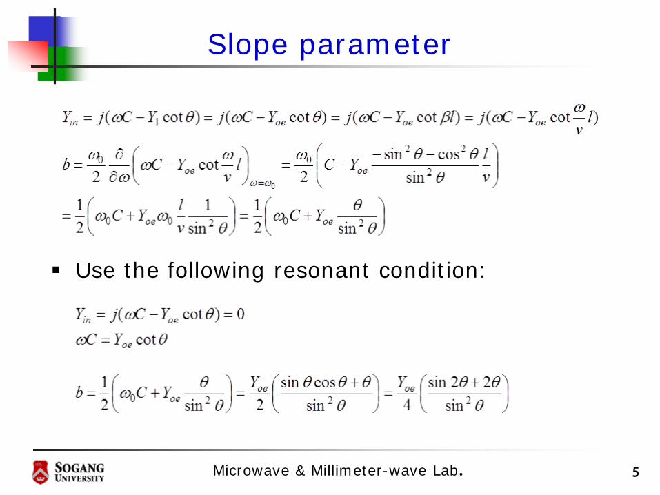
Slope parameter
5
Use the following resonant condition:

Microwave & Millimeter-wave Lab.
Coupling coefficient(1)
J-inverter:
Coupling coefficient:
6

Microwave & Millimeter-wave Lab.
Coupling coefficient(2)
Coupling coefficient inversely proportional to the frequency
7

Microwave & Millimeter-wave Lab.
Combline Bandapss Filter
8
Microwave & Millimeter-wave Lab.
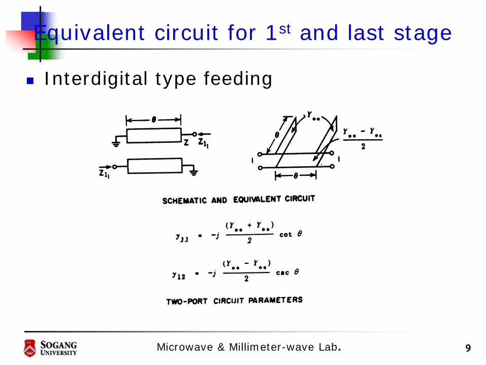
Equivalent circuit for 1st and last stage
Interdigital type feeding
9

Microwave & Millimeter-wave Lab.
Coupling stage
Combline type
10

Microwave & Millimeter-wave Lab.
Equivalent circuit(1)
Equivalent circuit
11

Microwave & Millimeter-wave Lab.
Design equations
12
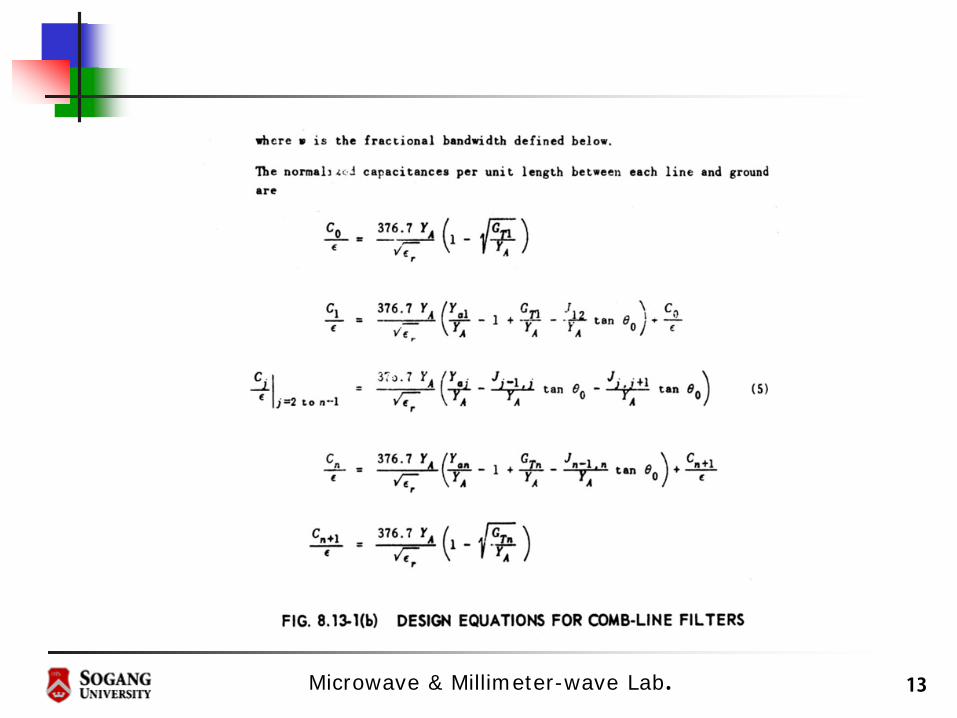
Microwave & Millimeter-wave Lab. 13

Microwave & Millimeter-wave Lab. 14

Microwave & Millimeter-wave Lab.
Equivalent circuit(2)
Reduced circuit
15

Microwave & Millimeter-wave Lab.
Equivalent circuits
16

Microwave & Millimeter-wave Lab.
Interdigital BPF-Introduction
Attractive features Very compact Required tolerances in manufacturing are
relatively relaxed because of the large spacing between resonator elements
The spurious response appears at there times the center frequency of the passband
The rates of cutoff and the strength of the stop bands are enhanced by multiple poles attenuation at dc and at even multiples of the passband center
17

Microwave & Millimeter-wave Lab.
Interdigital Bandpass Filter
Input feeding – shorted
30% bandwidth or less
18

Microwave & Millimeter-wave Lab.
Equivalent circuit
19
Y2 , lY1 , l Y3 , l
YA
1:N
Y12 , l Y23 , l Y34 , l
……
……

Microwave & Millimeter-wave Lab.
Design procedures
20

Microwave & Millimeter-wave Lab.
Design equations
21
Microwave & Millimeter-wave Lab.
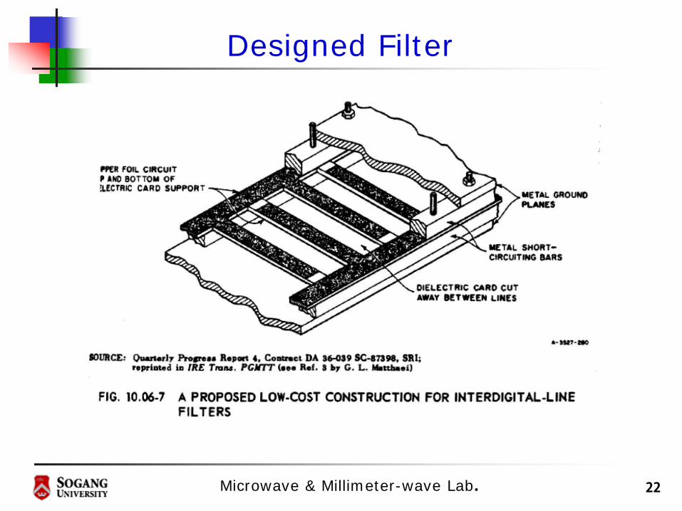
Designed Filter
22

Microwave & Millimeter-wave Lab.
Input feeding –Open
30% bandwidth or more
23

Microwave & Millimeter-wave Lab.
Equivalent circuit
24
J12 J23 J34
YA
b1 b3
J01
b2
YB

Microwave & Millimeter-wave Lab.
Design equations(1)
25

Microwave & Millimeter-wave Lab.
Design equations(2)
26

Microwave & Millimeter-wave Lab.
From Filter Specifications
27

Microwave & Millimeter-wave Lab.
Design Example
Open ended feeding At 2 GHz 10% bandwidth, Order 3
28

Microwave & Millimeter-wave Lab.
Layout of microstrip interdigital BPF
29
SPEC
Order : 3FBW : 10%Center frequency : 2GHzResonator width : 모두 같게 설계
Resonator lengthCase 1.
Case 2.
Substrate
Dielectric : 6.15H=1.27mmTanD : 0.0013
90oθ =
(1 )2 2
FBWπθ = −

Microwave & Millimeter-wave Lab. 30
Step 1- 에 따른 resonator length를 구한다.
Step 2
-slope parameter를 정해even mode addmittance값을 구할 수 있다.(resonator width)
Step 3-J inverter 값과 even mode addmittance값을 통해 odd mode addmittance값을 구한다.(resonator들 간의 간격 s)
θ
Layout of microstrip interdigital BPF
0
1
2
3
4
10.62920.97020.62921
ggggg
=====
01
12
23
34
0.11370.52080.52080.1137
JJJJ
====

Microwave & Millimeter-wave Lab.
Simulated Results(1)
31
(1 )2 2
FBWπθ = −90oθ =
Center frequency
: 1.952GHz
1dB BW
:210MHz(11%)

Microwave & Millimeter-wave Lab.
Simulated Results(2)
32
(1 )2 2
FBWπθ = −
Center frequency
: 2.040GHz
1dB BW
:210MHz(11%)