Integrated Framework Design for Intelligent Human Machine ...
85
Integrated Framework Design for Intelligent Human Machine Interaction by Jamil Akram Abou Saleh A thesis presented to the University of Waterloo in fulfilment of the thesis requirement for the degree of Master of Applied Science in Electrical and Computer Engineering Waterloo, Ontario, Canada, 2008 c Jamil Akram Abou Saleh 2008
Transcript of Integrated Framework Design for Intelligent Human Machine ...

Integrated Framework Design forIntelligent Human Machine Interaction
by
Jamil Akram Abou Saleh
A thesispresented to the University of Waterloo
in fulfilment of thethesis requirement for the degree of
Master of Applied Sciencein
Electrical and Computer Engineering
Waterloo, Ontario, Canada, 2008
c© Jamil Akram Abou Saleh 2008

I hereby declare that I am the sole author of this thesis. This is a true copy ofthe thesis, including any required final revisions, as accepted by my examiners.
I understand that my thesis may be made electronically available to the public.
ii

Abstract
Human-computer interaction, sometimes referred to as Man-Machine Interaction,is a concept that emerged simultaneously with computers, or more generally ma-chines. The methods by which humans have been interacting with computers havetraveled a long way. New designs and technologies appear every day. However,computer systems and complex machines are often only technically successful, andmost of the time users may find them confusing to use; thus, such systems are neverused efficiently. Therefore, building sophisticated machines and robots is not theonly thing someone has to address; in fact, more effort should be put to make thesemachines simpler for all kind of users, and generic enough to accommodate differ-ent types of environments. Thus, designing intelligent human computer interactionmodules come to emerge. In this work, we aim to implement a generic framework(referred to as CIMF framework) that allows the user to control the synchronizedand coordinated cooperative type of work that a set of robots can perform. Threerobots are involved so far: Two manipulators and one mobile robot. The frame-work should be generic enough to be hardware independent and to allow the easyintegration of new entities and modules. We also aim to implement the differentbuilding blocks for the intelligent manufacturing cell that communicates with theframework via the most intelligent and advanced human computer interaction tech-niques. Three techniques shall be addressed: Interface-, audio-, and visual-basedtype of interaction.
iii

Acknowledgments
The author would like to thank his supervisor, Professor Fakhreddine Karray, forhis guidance and support for this research work. The author would also like to ac-knowledge Jake Lifshits, Nours Arab, and Yuan Ren for their assistance and help.Many thanks are also due to my thesis readers, Dr. Sebastian Fischmeister, andDr. Behrad Khamesee for taking the time to assess my work.
iv

Contents
1 Introduction 1
1.1 Motivation . . . . . . . . . . . . . . . . . . . . . . . . . . . . . . . . 2
1.2 Objectives . . . . . . . . . . . . . . . . . . . . . . . . . . . . . . . . 2
1.3 Contributions . . . . . . . . . . . . . . . . . . . . . . . . . . . . . . 3
1.4 Thesis Organization . . . . . . . . . . . . . . . . . . . . . . . . . . . 5
2 Background And Literature Review 6
2.1 Unimodal Human Computer Interaction . . . . . . . . . . . . . . . 6
2.1.1 Visual-Based HCI . . . . . . . . . . . . . . . . . . . . . . . . 9
2.1.2 Audio-Based HCI . . . . . . . . . . . . . . . . . . . . . . . . 11
2.1.3 Sensor-Based HCI . . . . . . . . . . . . . . . . . . . . . . . . 12
2.2 Multi-Modal Human Computer Interaction . . . . . . . . . . . . . . 15
3 System’s Components: Special Software and Hardware Tools 19
3.1 Common Object Request Broker Architecture (CORBA) . . . . . . 19
3.1.1 Definition . . . . . . . . . . . . . . . . . . . . . . . . . . . . 19
3.1.2 Object Request Broker (ORB) . . . . . . . . . . . . . . . . . 21
3.1.3 Naming Service . . . . . . . . . . . . . . . . . . . . . . . . . 22
3.2 Hardware Components . . . . . . . . . . . . . . . . . . . . . . . . . 22
3.2.1 Manipulator F3 . . . . . . . . . . . . . . . . . . . . . . . . . 22
3.2.2 Manipulator A255 . . . . . . . . . . . . . . . . . . . . . . . 25
3.2.3 IRobot ATRV Mini . . . . . . . . . . . . . . . . . . . . . . . 25
v

4 System Architecture and Modules Integration 29
4.1 System Architecture . . . . . . . . . . . . . . . . . . . . . . . . . . 29
4.1.1 CORBA Name Service . . . . . . . . . . . . . . . . . . . . . 30
4.1.2 CIMF Server . . . . . . . . . . . . . . . . . . . . . . . . . . 30
4.1.3 CIMF Robot . . . . . . . . . . . . . . . . . . . . . . . . . . 32
4.1.4 CIMF Interface . . . . . . . . . . . . . . . . . . . . . . . . . 32
4.1.5 Protocol . . . . . . . . . . . . . . . . . . . . . . . . . . . . . 32
4.2 CIMF Interface Based Interaction . . . . . . . . . . . . . . . . . . . 34
4.3 Speech Recognition Module . . . . . . . . . . . . . . . . . . . . . . 37
4.3.1 Introduction . . . . . . . . . . . . . . . . . . . . . . . . . . . 37
4.3.2 Overview . . . . . . . . . . . . . . . . . . . . . . . . . . . . 38
4.3.3 Application Design . . . . . . . . . . . . . . . . . . . . . . . 42
4.3.4 Confidence Threshold Design . . . . . . . . . . . . . . . . . 47
4.4 Gesture Recognition and Fusion Modules . . . . . . . . . . . . . . . 48
4.4.1 Introduction . . . . . . . . . . . . . . . . . . . . . . . . . . . 48
4.4.2 Gesture Recognition Module . . . . . . . . . . . . . . . . . . 49
4.4.3 Type Feature Structures . . . . . . . . . . . . . . . . . . . . 49
4.4.4 Gesture Interpretation Module . . . . . . . . . . . . . . . . . 52
4.4.5 Speech Interpretation Module . . . . . . . . . . . . . . . . . 53
4.4.6 Fusion Module . . . . . . . . . . . . . . . . . . . . . . . . . 54
4.5 Framework Evaluation . . . . . . . . . . . . . . . . . . . . . . . . . 55
5 Face Recognition and Security 58
5.1 Overview on Biometrics . . . . . . . . . . . . . . . . . . . . . . . . 58
5.2 Face Recognition: Definition . . . . . . . . . . . . . . . . . . . . . . 60
5.3 System Architecture . . . . . . . . . . . . . . . . . . . . . . . . . . 61
5.4 Image Preprocessing . . . . . . . . . . . . . . . . . . . . . . . . . . 61
5.4.1 Histogram Equalization . . . . . . . . . . . . . . . . . . . . 62
5.4.2 Face Alignment . . . . . . . . . . . . . . . . . . . . . . . . . 62
vi

5.4.3 Normalization . . . . . . . . . . . . . . . . . . . . . . . . . . 64
5.5 Recognition . . . . . . . . . . . . . . . . . . . . . . . . . . . . . . . 64
5.6 Voting and Threshold Decisions . . . . . . . . . . . . . . . . . . . . 66
6 Conclusion and Future Work 69
Bibliography 70
vii

List of Figures
2.1 2D Facial scanner . . . . . . . . . . . . . . . . . . . . . . . . . . . . 10
2.2 Spectrograph in Voice Recognition . . . . . . . . . . . . . . . . . . 11
2.3 Samsung Haptic Cell Phone . . . . . . . . . . . . . . . . . . . . . . 14
2.4 Magnetic Levitation Haptic Joysticks . . . . . . . . . . . . . . . . . 15
2.5 Diagram of a Speech-Gesture Bimodal System . . . . . . . . . . . . 16
2.6 HMI in Neuro-Surgeries . . . . . . . . . . . . . . . . . . . . . . . . 18
3.1 CORBA Architecture . . . . . . . . . . . . . . . . . . . . . . . . . . 20
3.2 Manipulator Architecture . . . . . . . . . . . . . . . . . . . . . . . 23
3.3 Arm Architecture . . . . . . . . . . . . . . . . . . . . . . . . . . . . 24
3.4 Manipulator A255 Arm Architecture . . . . . . . . . . . . . . . . . 26
3.5 Ground Robot . . . . . . . . . . . . . . . . . . . . . . . . . . . . . . 27
3.6 24 Sonars ATRV Mini . . . . . . . . . . . . . . . . . . . . . . . . . 28
4.1 CIMF server Architecture . . . . . . . . . . . . . . . . . . . . . . . 31
4.2 CIMF Robots . . . . . . . . . . . . . . . . . . . . . . . . . . . . . . 33
4.3 Naming Registration . . . . . . . . . . . . . . . . . . . . . . . . . . 34
4.4 Registration Sequence . . . . . . . . . . . . . . . . . . . . . . . . . 35
4.5 CIMF Interface . . . . . . . . . . . . . . . . . . . . . . . . . . . . . 36
4.6 CIMF Interface . . . . . . . . . . . . . . . . . . . . . . . . . . . . . 37
4.7 Vocal Tract Anatomy . . . . . . . . . . . . . . . . . . . . . . . . . . 39
4.8 Recognized Keywords in the Speech Application . . . . . . . . . . . 43
viii
4.9 Flow Diagram of the Speech Application . . . . . . . . . . . . . . . 44
4.10 Locations Map . . . . . . . . . . . . . . . . . . . . . . . . . . . . . 45
4.11 Cooperation Between Manipulator A255 and Manipulator F3 . . . . 46
4.12 HandVu Gestures . . . . . . . . . . . . . . . . . . . . . . . . . . . . 50
4.13 HandVu Gestures . . . . . . . . . . . . . . . . . . . . . . . . . . . . 51
4.14 Interaction Overview of System’s Components . . . . . . . . . . . . 52
4.15 Architecture Tradeoff Analysis Method . . . . . . . . . . . . . . . . 57
5.1 System Architecture . . . . . . . . . . . . . . . . . . . . . . . . . . 61
5.2 Histogram Equalization . . . . . . . . . . . . . . . . . . . . . . . . . 62
5.3 Histogram Equalization . . . . . . . . . . . . . . . . . . . . . . . . . 63
5.4 Eye-Nose Template . . . . . . . . . . . . . . . . . . . . . . . . . . . 63
5.5 Template Matching Results . . . . . . . . . . . . . . . . . . . . . . 64
5.6 Normalized Faces . . . . . . . . . . . . . . . . . . . . . . . . . . . . 65
5.7 CCA Coefficients . . . . . . . . . . . . . . . . . . . . . . . . . . . . 67
5.8 Input Image and Distances in CCA Space . . . . . . . . . . . . . . 67
ix

Chapter 1
Introduction
The principles for applying human factors into machine interfaces has become thetopic of intense research work especially when equipment complexity began to ex-ceed the limits of human ability for right and safe operation. Computer systems andcomplex machines are often only technically successful, but most of the time usersmay find them confusing to use, inconsistent, difficult to learn; thus, the systemscannot be used effectively. Utilizing computers has always brought the concept ofinterfacing to the front. The methods by which human has been interacting withcomputers has been progressing fast for the last decades. New designs, technolo-gies and systems appear more and more every day affecting, not only the qualityof interaction, but also other branches in the history of human computer inter-action which have had great focus on the concepts of multimodality rather thanunimodality, intelligent adaptive interfaces rather than command/action ones, andfinally active rather than passive interfaces [1].
Research in human computer interaction (HCI) has been widely successful andhas largely changed computing. The ubiquitous graphical interface used by Mi-crosoft Windows 95 comes to be one of the examples. Another important exampleemerges from the fact that most of the softwares developed today employ user in-terface toolkits and some interface builders concepts. The remarkable growth ofthe World Wide Web is nothing but a direct consequence of HCI research: Oneis able to traverse a link across the world with a click of the mouse by applyinghypertext techniques to browsers [2]. HCI even goes beyond this; the belief thathumans will be able to interact with computers in conversational speech has beenfor a long time a favorite subject in science fiction, but with recent improvementsand developments in computer technology and in speech and language processing,
1

such systems are starting to become more feasible to design. There are significanttechnical problems that still need to be solved before speech driven interfaces be-come truly, but many promising results are making this fiction getting closer tobecome a truth.
1.1 Motivation
Human-computer interaction, sometimes referred to as Man-Machine Interactionor Interfacing, is a concept that emerged simultaneously with computers, or moregenerally machines. The reason, in fact, is loud and clear: If the user does notlike the introduction of a system and finds it confusing to use, then the system cannever be used efficiently. Increased attention to systems usability is also driven bythe need to increase productivity, reduce frustration, and reduce overhead costssuch as user training. For these reasons, the design of HCI should always addressboth terms: functionality and usability [3]. Why a system is actually designed canultimately be defined by what the system can do i.e., how the functions of a systemcan help towards the achievement of the purpose of the system. Functionality ofa system is defined by the set of actions or services that it provides to its users.However, the value of functionality is visible only when it becomes possible to beefficiently utilized by the user [4]. Usability of a system with a certain functionalityis the range and degree by which the system can be used efficiently and adequatelyto accomplish certain goals for certain users. The actual effectiveness of a systemis achieved when there is a proper balance between the functionality and usabilityof a system [5].
Having these concepts in mind and considering that the terms computer, machineand system are often used interchangeably in this context, HCI is a design thatshould produce a fit between the user, the machine and the required services in or-der to achieve a certain performance both in quality and optimality of the services[6].
1.2 Objectives
”Most sophisticated machines are worthless unless they can be used properly bymen” [3]. This basic argument simply presents the main terms that should beconsidered in the design of HCI: functionality and usability. Our principal goalin this research work is to implement the different building blocks for a generic
2

intelligent manufacturing cell that allow the user to easily control a set of robotsusing the most intelligent and advanced human computer interaction techniques.To achieve this, the following tasks should be completed:
• Build a generic framework that connects the set of robots to one manufactur-ing cell. The framework must be hardware independent, and must allow foreasy addition of new entities. It must also allow for easy implementation ofnew tasks. Finally, it must allow for easy remote operation and observationby an arbitrary number of operators and observers.
• Implement a friendly computer interface that enables a simple and easy accessto the framework.
• Build intelligent speech and gesture recognition based entities that allow theuser to control the system with natural speech commands, some predefinedhand gestures, or a combination of both.
• Enable remote access to the system.
• Implement a face recognition based authentication system to introduce ahigher level of security to our framework.
1.3 Contributions
Building sophisticated machines and robots is definitely not the only thing someonehas to address; more effort should be put on making the use of these machines easierfor all kinds of end users. Most nowadays systems are too technical and seem tobe confusing to use by normal users; besides, they tend to lack the generic aspectthat makes them usable under different environments and conditions. In this work,two principal goals are addressed. The first main goal is to implement a frameworkthat is generic enough to accommodate for a number of key issues:
• The framework must be hardware independent.
• The framework must allow for easy addition of new entities.
• The framework must allow for easy implementation of new tasks.
• The framework must allow for easy remote operation and observation by anarbitrary number of operators and observers.
3

The framework will be called CIMF framework, so keywords ”framework” and”CIMF framework” will be used interchangeably. The second principal goal is toimplement and integrate into the framework the different building blocks for theintelligent manufacturing cell that controls a set of robots using the most intelligentand advanced human computer interaction techniques. Three techniques shall beaddressed: Interface based interaction, audio based interaction and visual basedinteraction.
Human-Computer Interface Design seeks to discover the most efficient way to de-sign understandable work frame. Research in this area is voluminous; a completebranch of computer science is devoted to this topic, with recommendations for theproper design of menus, icons, forms, as well as data display and entry screens. Theinterface should be friendly enough to allow non professional users to interact withsophisticated machines freely and easily.
The audio based interaction between a computer and a human is another importantarea of HCI systems. This area deals with information acquired by different audiosignals. While the nature of audio signals may not be as variable as visual signalsbut the information gathered from audio signals can be more trustable, helpful, andis some cases unique providers of information. Speech recognition is used in thiswork; thus allowing users to provide speech commands to the system. The majorproblem in speech recognition though, is the inability to predict exactly what a usermight say. We can only know the keywords that are needed for a specific speechenabled system. Fortunately, that’s all we need in order to interact adequately withthe machine. So a proper design of a system that spots these specific terms in theuser utterance (also called as keyword spotting system) can help overcoming thisparticular problem, and hence allowing users to speak in a more natural way.
Finally, the visual based human computer interaction which is probably the mostwidespread area in HCI research allows user to interact with the system with somespecific visual features. Hand gesture recognition is used for this research work tocontrol our manufacturing cell. And in order to provide the system with a higherlevel security layer, another visual based interaction module is implemented andintegrated to the system in order to authenticate people and hence allowing or pre-venting them from accessing the system. Face recognition is used for this purpose.
Human machine interaction however does not have to be performed with physicalproximity. In fact, the human operators and the target machines can be separatedby distances of up to several thousand miles, but the performed actions should yield
4
anomalous results that are comparable in scale and character to those producedunder conditions of physical proximity. For this reason, the framework was imple-mented to allow remote access to it. Different modules and entities can connectfrom anywhere to the framework after the user has been properly authenticated.
1.4 Thesis Organization
The remainder of this thesis is organized as follows. Chapter 2 reviews the stateof the art of human machine interaction systems and techniques. Chapter 3 givesan overview of the system’s main hardware and software components. Chapter 4provides a detailed description of the generic implementation of the framework,and of the different building blocks of the intelligent manufacturing cell. The im-plementation of interface−, audio−, and visual−based type of interaction modulesare discussed in this chapter. Chapter 5 presents the structure and implementationof another visual based human computer interaction, the face recognition, that isused to provide a more secure environment by authenticating those who are autho-rized to access the system. Finally, chapter 6 summarizes the contributions of thisthesis and introduces the focus of the future research.
5

Chapter 2
Background And LiteratureReview
This chapter reviews the state of the art of what has been achieved in humancomputer/machine interaction. Both unimodal and multimodal types of interactionare addressed.
2.1 Unimodal Human Computer Interaction
For most people, a wide conceptual gap does exist between the representationsthat computers will accept when they are programmed, and the representationsthat they use in their minds when thinking about a problem. People who are notprofessionally trained programmers find it really difficult to move closer to the sys-tem. The biggest issue is in fact that even if they learn the techniques, they tendnot to like the results. They just don’t want to think like computers, but they dowant to control them. For the past three decades, many attempts has been tak-ing place to enable regular non professional programmers to program computers.Researchers have created many languages such as Smalltalk, Logo, Pascal, BASIC,and HyperTalk. They developed techniques such as structured programming, andapproached programming from a pedagogical perspective with technology, such asthe goal-plan editor, and from an engineering perspective, with CASE tools. Eachof these is a brilliant advance in its own right. Today, however, only a small per-centage of people program computers, probably less than 1 percent. The secret toincrease this rate is to make programming more like thinking. A research projectat Apple Computer has attempted to do this for childrens programming tools. The
6

key idea is to use representations in the computer that are similar and analogousto the objects being represented and to allow direct manipulations of these repre-sentations during the process of programming. The key to success if to address andexplore the fields of HCI, contextual inquiry, Visual Design and Interface techniques.
The methods by which human has been interacting with computers has made along way. Research in this area has been growing very fast in the last few decadesand new designs of technologies and systems appear every day. The journey stillcontinues. The rapid growth of information systems has led to the wide develop-ment of research on human computer interaction (HCI) that aims at the designingof human computer interfaces that present ergonomic properties, such as friend-liness, usability, and transparency. The growth in Human-Computer Interaction(HCI) field has experienced different branching in its history, and went to focuson the concepts of multimodality rather than just unimodality, intelligent adaptiveinterfaces rather than command/action ones, and also active rather than passiveinterfaces.
HCI, often called as Man-Machine Interaction or Interfacing, has emerged simulta-neously with computers, or more generally machines. The reason, in fact, is clear:Even the most technically successful machines are worthless unless they can be usedproperly and safely by humans. From this argument, one can simply present themain terms that should be addressed when designing a human computer interac-tion system: functionality and usability [3]. The design of an HCI system affectsthe amount of effort that the user has to expend in order to provide inputs forthe system and to interpret the outputs of the system, as well as how much effortit takes to learn how to do this. Hence, HCI is a design that should produce abalance and a fit between the user, the machine and the required services in orderto achieve a certain performance both in quality and optimality of the services [6].
HCI design should consider many aspects of human behaviors in order to be useful.Therefore, when designing an HCI system, the degree of activity that involves a userwith a machine should be continuously considered. This activity happens to occuron three different levels: physical [7], cognitive [8], and affective [9]. The physicalaspect addresses the mechanics of interaction between humans and machines. Thecognitive aspect, on the other hand, is more about how users can understand andinteract with the system. Finally, the affective aspect tries to make the interactiona pleasurable experience for the user, and intend to affect the user in a way thatmake him continue to use the machine by changing its attitudes and emotions [1].The existing physical technologies for HCI can be categorized according to the rel-
7

ative human sense that the device is designed to address. These devices basicallyrely on three human senses: vision, audition, and touch [3].
Input devices that rely on vision are commonly either switch-based or pointingdevices. Such devices are the most commonly used type [10, 11]. The switch-based devices use buttons and switches as in a keyboard [12]. Pointing devices, onthe other hand, are more like mice, joysticks, touch screen panels, graphic tablets,trackballs, and pen-based input [13]. Joysticks are in fact the ones that have bothswitches and pointing abilities. The output devices can be any kind of visual displayor printing device [5]. The devices that rely on audition are more advanced devicesthat aim to facilitate the interaction, and are much more difficult to build [14, 15].However, output auditory devices are easier to create, where all kind of messagesand speech signals are produced by machines as output signals. Beeps, alarms, andturn-by-turn navigation commands of a GPS device are simple examples [1].
The most difficult and costly devices to build are haptic devices [16]. ”These kindsof interfaces generate sensations to the skin and muscles through touch, weightand relative rigidity [3]”. Haptic technology refers to the technology that interfaceswith the user via the sense of touch, by applying forces, vibrations or motions.This mechanical stimulation may be used to assist in creating virtual objects thatare only existing in a computer simulation, to control such virtual objects, and toenhance the remote control of machines and devices. This emerging technologypromises to have wide reaching applications. For example, haptic technology hasmade it possible to investigate in detail how the human sense of touch works, byallowing the creation of carefully-controlled haptic virtual objects. These objectsare used to systematically probe human haptic capabilities. Haptic devices [17] aregenerally made for virtual reality [18] or disability assistive applications.
The recent advances and technologies in HCI are now trying to combine formermethods of interaction together along with other emerging technologies such asnetworking and animation [1]. These new advances can be categorized in threesections: wearable devices [19], wireless devices [20], and virtual devices [21]. Thetechnology is improving so fast that even the borders between these new technolo-gies are fading away as it is the case for example when talking about GPS navi-gation systems [22], military super-soldier enhancing devices (e.g. thermal vision[23], tracking other soldier movements using GPS, and environmental scanning),radio frequency identification (RFID) products, personal digital assistants (PDA),and virtual tour for real estate business [24]. Some of these new devices upgradedand/or integrated previous methods of interaction. Such an example comes to be
8

Canesta keyboard that has been offered by Compaq’s iPAQ, which is a virtual key-board that is made by projecting a QWERTY like pattern on a solid surface usinga red light. The device tries to track user’s finger movement while typing on thesurface with a motion sensor [25].
As mentioned earlier, an interface mainly relies on the number and diversity ofits inputs and outputs which are communication channels that enable users to in-teract with computer via this interface. Each of the different independent singlechannels is called a modality. A system that is based on only one modality is calledunimodal. Based on the nature of different modalities, they can be divided intothree categories:
• Visual-Based.
• Audio-Based.
• Sensor-Based.
The next sub-sections describe each category and provide examples and referencesto each category.
2.1.1 Visual-Based HCI
The visual based human computer interaction is probably the most widespread areain HCI research. Face recognition comes to be one of these main aspects due to itshigh relation to security issues. Scanners come to emerge as an advanced techniqueused in this field as shown in Figure 2.1. Some of the other main research areas inthis section are as follow [1]:
• Facial Expression Analysis (Emotion Recognition).
• Body Movement Tracking (Large-scale).
• Gesture Recognition.
• Gaze Detection (Eyes Movement Tracking).
Facial expression analysis generally deals with recognition of emotions visually[26, 27, 28]. Some proposed an emotion recognition system that uses the majordirections of specific facial muscles, while others used parametric models to extract
9
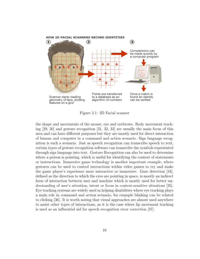
Figure 2.1: 2D Facial scanner
the shape and movements of the mouse, eye and eyebrows. Body movement track-ing [29, 30] and gesture recognition [31, 32, 33] are usually the main focus of thisarea and can have different purposes but they are mostly used for direct interactionof human and computer in a command and action scenario. Sign language recog-nition is such a scenario. Just as speech recognition can transcribe speech to text,certain types of gesture recognition software can transcribe the symbols representedthrough sign language into text. Gesture Recognition can also be used to determinewhere a person is pointing, which is useful for identifying the context of statementsor instructions. Immersive game technology is another important example, wheregestures can be used to control interactions within video games to try and makethe game player’s experience more interactive or immersive. Gaze detection [34],defined as the direction to which the eyes are pointing in space, is mostly an indirectform of interaction between user and machine which is mostly used for better un-derstanding of user’s attention, intent or focus in context-sensitive situations [35].Eye tracking systems are widely used in helping disabilities where eye tracking playsa main role in command and action scenario, for example blinking can be relatedto clicking [36]. It is worth noting that visual approaches are almost used anywhereto assist other types of interactions, as it is the case where lip movement trackingis used as an influential aid for speech recognition error correction [37].
10

2.1.2 Audio-Based HCI
The audio based interaction between a computer and a human is another importantarea of HCI systems. This area deals with the information that is acquired bydifferent audio signals. This information may not be as variable as visual signals butcan be for most cases more trustable, helpful, and unique providers of information.Research areas in this field can be divided to the following areas [1]:
• Speech Recognition
• Speaker Recognition
• Auditory Emotion Analysis
• Human-Made Noise/Sign Detections (Gasp, Sigh, Laugh, Cry, etc.)
• Musical Interaction
Figure 2.2: Spectrograph in Voice Recognition
11

Historically, speech recognition [14] and speaker recognition [38] have been themain focus of researchers. Speaker recognition is built based on the extractionand modeling of specific features from speech. This voice authentication processis based on an analysis of the vibrations created in the human vocal tract. Theshape of a person’s vocal tract determines the resonance of the voice which is fairlydifferent from one to another due to the fact that everyone has a unique vocal tractin shape and size. Speech recognition ,on the other hand, is about converting thespeech signal into a readable input. Speech recognition will be addressed in detailsin chapter 4. Figure 2.2 shows the spectrogram of the word that is used to visualizethe acoustics of vowels which counts as one of the most important steps in speechrecognition. Recent endeavors to integrate human emotions in intelligent humancomputer interaction initiated the efforts in analysis of emotions in audio signals[39, 40]. A speech consists of some words spoken in a particular way in which theinformation about emotions resides. Emotions affect the open/close ratio of thevocal chords, and hence the quality of the voice. Sadness for example influencesthe voice quality so that creaky voice may be produced. In this case the speech isof low pitch and low intensity [41]. Other than the tone and pitch of speech data,typical human auditory signs such as sigh, gasp, and etc helped emotion analysisfor designing more intelligent HCI system [42]. Music generation and interactionis a very new area in HCI that finds its most interesting applications in the artindustry. [43].
2.1.3 Sensor-Based HCI
Sensor-based interactions are increasingly becoming an essential part in the designof user experiences. This type of interaction ranges from the activation of controlsto providing some context-aware information by delivering relevant informationto people at appropriate times. Sensor-based interaction can be considered as acombination of variety of areas with a wide range of applications, where at least onephysical sensor is used between the user and machine to provide better interaction.These sensors as shown below can be very primitive or very sophisticated [1].
• Pen-Based Interaction.
• Mouse and Keyboard.
• Joysticks.
• Motion Tracking Sensors and Digitizers.
12

• Haptic Sensors.
• Pressure Sensors.
• Taste/Smell Sensors.
Pen-Based sensors are specifically of interest in mobile devices and are related topen gesture [44] and handwriting recognition areas. An interesting application isthe Biometric Smart Pen (BiSP), which is a multi-sensor pen that is used for theacquisition of neuro-motor features by measuring the kinematics and dynamics ofhand movements during handwriting, i.e. the pressure applied to the pen and thetilt angles. This syetem is used for the authentication of individuals where querysamples are compared against stored references using some matching algorithms[45]. Motion tracking sensors/digitizers are state-of-the-art technology which revo-lutionized movie, animation, art, and video-game industry. They come in the formof wearable cloth or joint sensors and made computers much more able to interactwith reality and human able to create their world virtually. A motion capture ses-sion records the movements of the actor as animation data which are later mappedto a 3D model like a human, a giant robot, or any other model created by a com-puter artist, and then make the model move the same way as recorded. This iscomparable to older techniques where the visual appearance of the motion of anactor was filmed and used as a guide for the frame by frame motion of a hand-drawnanimated character.
Haptic and pressure sensors are of special interest for applications in roboticsand virtual reality as well [16, 17]. New humanoid robots include hundreds of hap-tic sensors that make the robots sensitive to touch [46, 47]. These types of sensorsare also used in medical surgery applications and cell phone designs. Figure 2.3shows Samsung’s Anycall Haptic cell phone. The phone, launched in South Koreain March, 2008, has a large touch-screen display that also provides haptic feedbackwhen using certain functions on the device. There are 22 kinds of vibration in totalbuilt into the phone.
Another important emerging haptic device is a controller developed by Ralph L.Hollis, a research professor and a director of the Microdynamic Systems Laboratoryat Carnegie Mellon University. The controller allows computer users to explore vir-tual environments with three-dimensional images through sight, sound, and mostimportantly sense of touch [48]. The controller has just one moving part and lookslike a joystick with a levitating bar that can be grasped and moved in any direc-tion. The device has six degrees of freedom of movement: forward, backwards, left,
13

Figure 2.3: Samsung Haptic Cell Phone
right, up and down, and rests in a bowl that is connected to a computer as shownin Figure 2.4. The device is equipped with magnets that exert feedback forces onthe bar in order simulate resistance, weights, and/or friction. The forces are strongenough to make objects resist as much as 40 newtons of force before they shift evena millimetre. ”The device can track movements of the bar as small as two microns,a fiftieth the width of a human hair, which is very important for feeling the verysubtle effects of friction and texture” [49].
According to Ralph L, this device ”simulates a hand’s responses to touch be-cause it relies on a part that floats in a magnetic field rather than on mechanicallinkages and cables”. It cost much less than 50, 000 dollars, and ”could enable awould-be surgeon to operate on a virtual human organ and sense the texture oftissue or give a designer the feeling of fitting a part into a virtual jet engine, ormight also be used to convey the feeling of wind under the wings of unmannedmilitary planes” [48]. The system was presented at the IEEE Symposium on Hap-tic Interfaces for Virtual Environments and Teleoperator Systems that was held onMarch 13, 2008.
14

Figure 2.4: Magnetic Levitation Haptic Joysticks
2.2 Multi-Modal Human Computer Interaction
The term multimodal refers to combination of multiple modalities, or communica-tion channels [50]. The definition of these channels is inherited from human typesof communication: Sight, Hearing, Touch, Smell, and Taste. A multimodal inter-face acts as a facilitator of human computer interaction via two or more modesof input that go beyond the traditional keyboard and mouse. The exact numberof supported input modes, their types and the way in which they work togethermay vary widely from one multimodal system to another. Multimodal interfacesincorporate different combinations of speech, gesture, gaze, facial expressions andother non-conventional modes of input. One of the most commonly supported com-binations of input methods is that of gesture and speech [51]. Figure 2.5 presentsthe structure of such system.
15

Although an ideal multimodal HCI system is a combination of single modali-
Figure 2.5: Diagram of a Speech-Gesture Bimodal System
ties that interact correlatively, the practical boundaries and open problems in eachmodality introduce limitations on the fusion of different modalities. In spite of allthe progress made in MMHCI, in most of existing multimodal systems, the modal-ities are still treated separately and only at the end, results of different modalitiesare combined together.
The reason is that the open problems in each area are yet to be perfected; meaningthat there is still much work to be done to acquire a reliable tool for each sub-area. Moreover, roles of different modalities and their share in interplay are notscientifically known. ”Yet, people convey multimodal communicative signals in acomplementary and redundant manner. Therefore, in order to accomplish a human-like multimodal analysis of multiple input signals acquired by different sensors, thesignals cannot be considered mutually independently and cannot be combined in acontext-free manner at the end of the intended analysis but, on the contrary, the
16

input data should be processed in a joint feature space and according to a context-dependent model. In practice, however, besides the problems of context sensingand developing context-dependent models for combining multisensory information,one should cope with the size of the required joint feature space. Problems includelarge dimensionality, differing feature formats, and time-alignment. [50]”
An interesting aspect of multimodality is the collaboration of different modali-ties to assist the recognitions. For example, lip movement tracking (visual-based)can help speech recognition methods (audio-based) and speech recognition methods(audio-based) can assist command acquisition in gesture recognition (visual-based).
An important application of intelligent multimodal systems come to appear inmedicine. By the early 1980s, surgeons were beginning to reach their limits basedon traditional methods alone. The human hand was infeasible for many tasks andgreater magnification and smaller tools were needed. Higher precision was requiredto localize and manipulate within small and sensitive parts of the human body.Digital robotic neuro-surgery has come as a leading solution to these limitationsand emerged fast due to the vast improvements in engineering, computer technologyand neuro-imaging techniques. Robotics surgery was introduced into the surgicalarea [52]. State University of Aerospace Instrumentation, University of Karlsruhe(Germany) and Harvard Medical School (USA) have been working on developingman-machine interfaces, adaptive robots and multi-agent technologies intended forneuro-surgery [53].
The neuro-surgical robot consists of the following main components: An arm, feed-back vision sensors, controllers, a localization system and a data processing center.Sensors provide the surgeon with feedbacks from the surgical site with real-timeimaging, where the latter one updates the controller with new instructions for therobot by using the computer interface and some joysticks. Neuro-surgical robotics(as shown in Figure 2.6) provide the ability to perform surgeries on a much smallerscale with much higher accuracy and precision, giving access to small corridorswhich is important in brain surgery [52].
Another important field in which multimodality comes to emerge is the domainof biometric recognition, which refers to automatic recognition of individuals ac-cording to some specific physiological and/or behavioral features. It is importantto notice that a biometric system that is based on one single biometric metric doesnot always come to meet the desired performance requirements; thus, multimodalbiometric systems come to emerge. Consider, for example, a network logon appli-
17
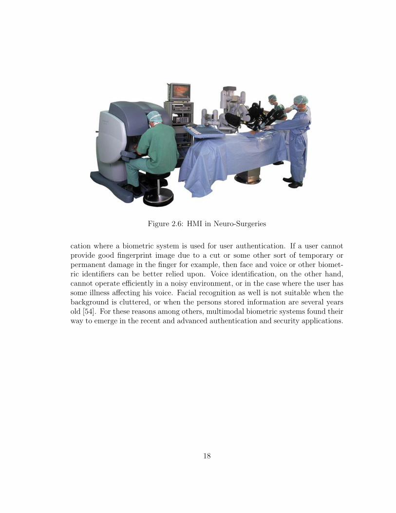
Figure 2.6: HMI in Neuro-Surgeries
cation where a biometric system is used for user authentication. If a user cannotprovide good fingerprint image due to a cut or some other sort of temporary orpermanent damage in the finger for example, then face and voice or other biomet-ric identifiers can be better relied upon. Voice identification, on the other hand,cannot operate efficiently in a noisy environment, or in the case where the user hassome illness affecting his voice. Facial recognition as well is not suitable when thebackground is cluttered, or when the persons stored information are several yearsold [54]. For these reasons among others, multimodal biometric systems found theirway to emerge in the recent and advanced authentication and security applications.
18

Chapter 3
System’s Components: SpecialSoftware and Hardware Tools
In this chapter, we describe the different systems’ main components. Both softwareand hardware tools and components are presented. In our framework, differentmodules and entities are implemented using different computer languages (C++,Java, and Python); thus, the common object request broker architecture (CORBA)was addressed. Three robots are involved so far in the framework: ManipulatorF3, manipulator A255, and ATRV mini robot (also called as ground robot). Thedescription of these robots shall be presented in this chapter.
3.1 Common Object Request Broker Architec-
ture (CORBA)
3.1.1 Definition
The Common Object Request Broker Architecture (CORBA), shown in Figure 3.1,is a standard defined by the Object Management Group (OMG) that enables soft-ware components written in multiple computer languages and running on multiplecomputers to work together. CORBA is a mechanism in software for normaliz-ing the method-call semantics between application objects that reside either in thesame address space (application) or remote address space (same host, or remotehost on a network).
19

CORBA uses an interface definition language (IDL) to specify the interfaces thatobjects will present to the outside world. CORBA then specifies a ”mapping” fromIDL to a specific implementation language like C++ or Java. Standard mappingsexist for Ada, C, C++, Lisp, Smalltalk, Java, COBOL, PL/I and Python. Thereare also non-standard mappings for Perl, Visual Basic, Ruby, Erlang, and Tcl im-plemented by object request brokers (ORBs) written for those languages.
The CORBA specification dictates that there shall be an ORB (Object Request
Figure 3.1: CORBA Architecture
Broker) through which the application interacts with other objects. In practice, theapplication simply initializes the ORB, and accesses an internal Object Adapterwhich maintains such issues as reference counting, object (reference) instantiationpolicies, object lifetime policies, etc. The Object Adapter is used to register in-stances of the code classes. Generated code classes are the result of compiling theuser IDL code which translates the high-level interface definition into an OS- andlanguage-specific class base for use by the user application. This step is necessaryin order to enforce the CORBA semantics and provide a clean user processes for
20

interfacing with the CORBA infrastructure.
Some IDL language mappings are more hostile than others. For example, dueto the very nature of Java, the IDL-Java Mapping is rather trivial and makes usageof CORBA very simple in a Java application. The C++ mapping is not trivial butaccounts for all the features of CORBA, i.e. exception handling. The C-mappingis even more strange, but it does make sense and handles the RPC (Remote Pro-cedural Call) semantics just fine.
A ”language mapping” requires that the developer (”user” in this case) createsome IDL code representing the interfaces to his objects. Typically a CORBA im-plementation (either an Open Source or commercial product) comes with a toolcalled an IDL compiler. This compiler will convert the user’s IDL code into somelanguage-specific generated code. The generated code is then compiled using a tra-ditional compiler to create the linkable-object files required by the application.
3.1.2 Object Request Broker (ORB)
The ORB is the distributed service that implements the request to the remote ob-ject. It locates the remote object on the network, communicates the request to theobject, waits for the results and when available communicates those results back tothe client.
The ORB implements location transparency. Exactly the same request mecha-nism is used by the client and the CORBA object regardless of where the object islocated. It might be in the same process with the client, down the hall or acrossthe planet. The client cannot tell the difference.
The ORB implements programming language independence for the request. Theclient issuing the request can be written in a different programming language fromthe implementation of the CORBA object. The ORB does the necessary transla-tion between programming languages. Language bindings are defined for all popularprogramming languages.
21

3.1.3 Naming Service
The naming service is a standard service for CORBA applications, defined in theObject Management Group’s (OMG) CORBA services specification. The namingservice allows you to associate abstract names with CORBA objects and allowsclients to find those objects by looking up the corresponding names. This serviceis both simple and useful.
A server that holds a CORBA object binds a name to the object by contactingthe naming service. To obtain a reference to the object, a client requests the Nam-ing Service to look up the object associated with a specified name. This is knownas resolving the object name. The Naming Service provides interfaces defined inIDL that allow servers to bind names to objects and clients to resolve those names.
Most CORBA applications make some use of the Naming Service. Locating aparticular object is a common requirement in distributed systems and the NamingService provides a simple, standard way to do this.
3.2 Hardware Components
In this section, a general description of the robots involved in the framework willbe presented. Two manipulators (manipulator F3 and manipulator A255) and onemobile robot (ATRV mini robot) are so far integrated into the framework. Butsince out presented framework is hardware independent, more robots and entitiescan be easily integrated into the system.
3.2.1 Manipulator F3
At its most basic configuration, the F3 robot system, a trademark of ThermoCRC, shown in Figure 3.2, consists of an F3 robot arm, a C500C controller, andan umbilical cable that provides power and communication from the controller tothe arm. Commands are issued to the robot system from program applications orterminal commands, or through the teach pendant. End effectors such as grippersand other tools enable the arm to perform specialized tasks [55].
22

Figure 3.2: Manipulator Architecture
The Arm
The arm transports payloads and performs other motion tasks in space. A mount-ing plate at its base secures the arm to a fixed platform or track. One can easilymount a variety of end effectors such as grippers, dispensers, or deburring tools onthe ISO-standard tool flange.
Articulated joints provide the arm with six degrees of freedom, allowing the userto accurately position the tool flange at any point within the work space, from anyorientation.
Absolute encoders in each joint provide continuous information on arm stance andposition. When the robot system is turned off, this information is retained in mem-ory, ensuring that the location and orientation of all axes is exactly known at alltimes. Under normal operation, the F3 arm does not need to be homed.
23
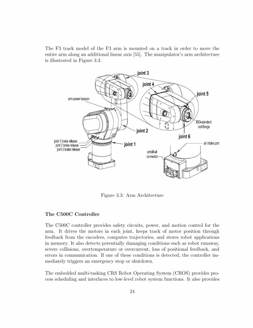
The F3 track model of the F3 arm is mounted on a track in order to move theentire arm along an additional linear axis [55]. The manipulator’s arm architectureis illustrated in Figure 3.3.
Figure 3.3: Arm Architecture
The C500C Controller
The C500C controller provides safety circuits, power, and motion control for thearm. It drives the motors in each joint, keeps track of motor position throughfeedback from the encoders, computes trajectories, and stores robot applicationsin memory. It also detects potentially damaging conditions such as robot runaway,severe collisions, overtemperature or overcurrent, loss of positional feedback, anderrors in communication. If one of these conditions is detected, the controller im-mediately triggers an emergency stop or shutdown.
The embedded multi-tasking CRS Robot Operating System (CROS) provides pro-cess scheduling and interfaces to low-level robot system functions. It also provides
24

basic application development tools, including the application shell (ash), an inte-grated environment for developing, compiling, and running robot applications onthe controller.
The E-Stop
Emergency stops, or e-stops, are a safety feature designed to stop the arm in case ofemergency. The E-Stop buttons provided with the system are large red, palm-capbuttons. One can also add automatic e-stop devices such as pressure-sensitive matsor safety interlocks to the robot system.
When an e-stop is triggered, power is immediately removed from the arm mo-tors and fail-safe brakes automatically engage to prevent the arm from moving dueto gravity. To prevent the payload from being dropped, servooperated tools remainpowered and pneumatic tools retain their last state. To ensure safety, power cannotbe restored to the arm until the E-Stop device that triggered the emergency stopis manually reset.
3.2.2 Manipulator A255
Manipulator A255, another product of Thermo CRS, is very similar in architecture,design and functionality to manipulator F3. The A255 arm however is articulatedwith five joints or axes (instead of six in the case of F3 arm), providing it with fivedegrees of freedom as shown in Figure 3.4. This allows the arm to move a gripperor other tool to cartesian spatial coordinates and orientation defined by X, Y, Z,Z-rotation, Y-rotation, and X-rotation [56]. The A255 robot system also consistsof a C500C controller that is identical to that of manipulator F3. Since most ofthe description applied to manipulator F3 also applies to manipulator A255, thedetailed technical description of this manipulator is skipped in this section to avoidredundancy.
3.2.3 IRobot ATRV Mini
The ATRV Mini, shown in Figure 3.5, is a ground robot development platformby iRobot. All development should be done under the mobility account. TheATRV connects to the network through a wireless bridge. It is configured as min-nie.uwaterloo.ca on the university network. Files can be uploaded to the robot
25

Figure 3.4: Manipulator A255 Arm Architecture
using ftp. Mobility is the name of the development framework provided by iRobotand used to develop for the ATRV. Its framework is available in C++ and Java.The C++ version is currently installed on the robot. Mobility is comprised of alarge number of components that communicate using CORBA. The robot can alsoconnect to the CIM Framework by implementing the CIMFRobot interface. Severalfeatures are provided by ATRV mini robots. Some main ones are:
Emergency Stop Buttons
The most important safety features on your ATRV-Mini robot are the EmergencyStop Buttons (sometimes referred to as e-stop buttons or kill switches). Theselarge, conspicuous red buttons are mounted on the top of your robot at the tworear corners. Pushing any of the emergency stop buttons at any time will halt theATRV-Mini [57].
26

Figure 3.5: Ground Robot
Drive Enable Key
The Drive Enable Key on ATRV-Mini mobile robot enables or disables all activityof the robots motors by activating the e-stop circuit (the brakes cannot be turnedoff). Simply turning the key to the OFF position (vertical) will disable motion.The drive enable key must be inserted and turned to the ON position (horizontal)to enable the robots motor drive. With the drive enable key removed, one cansafely use the integrated computer systems as development and testing platformsfor the robot software, without fear that the robot will accidentally move undersoftware control.
Sonar
The ATRV-Mini robot comes with either 16 or 24 sonars. In the 16-sonar con-figuration, there are 12 on the front and four on the back [57]. In the 24-sonarconfiguration, there are 12 on the front and 12 on the back. Figure 3.6 shows the24-sonar configuration of ATRV-Mini robot.
27

The ATRV mini robot is also supported with a 15-pin Joystick port that is usedto connect a standard PC joystick so one can manually drive the mobile robot.ATRV-Mini comes with two BreezeCom antennas for wireless ethernet communi-cation between the user and the robot. The ethernet port allows direct connectionto an Ethernet network.
Figure 3.6: 24 Sonars ATRV Mini
28

Chapter 4
System Architecture and ModulesIntegration
In this chapter, the framework architecture, among the design and implementa-tion the different interaction modules are presented. Interface−, audio−, andvisual−based type of interactions are addressed.
4.1 System Architecture
The Computer Integrated Manufacturing Framework (called CIMF framework) isa software framework designed to interconnect and control a number of roboticentities. It has been designed and tested in the Computer Integrated ManufacturingLab at the University of Waterloo. The goal of the framework is to address a numberof key issues:
• The framework must be hardware independent.
• The framework must allow for easy addition of new entities.
• The framework must allow for easy implementation of new tasks.
• The framework must allow for easy remote operation and observation by anarbitrary number of operators and observers.
29

4.1.1 CORBA Name Service
A CORBA naming service must be running prior to any other component of theframework. The name server is required to facilitate CORBA communication andto aid the framework components in identifying each other on the network. Anynaming service that is compliant with the CORBA standard would work; howeverduring development the orb naming service as provided with the Java developmentkit was used exclusively.
4.1.2 CIMF Server
The server is the central entity of the framework that connects the various compo-nents to one another. As each of the robotics entities turn on, it contacts the serverregistering itself along with its capabilities. In this way the server keeps a recordof all active robots and their states. This information can then become availableto other robots or interfaces by request. The server further acts as a dispatcher,keeping a queue of instructions for each robot. This allows multiple robots to becontrolled simultaneously. Figure 4.1 illustrates a simplified data flow view of theserver. The main components of the server are: Robot store, task queue, scheduler,dispatcher, and monitor.
Robot Store
The robot store contains records of all currently connected robots, their actions,locations, and various other information. By keeping a record of this on the serverrather than retrieve it every time it is requested, a significant amount of networktraffic is eliminated.
Task Queue
The task queue contains sequences of task that need to be executed. It consists ofa list of parallel tasks, where each parallel task is a collection of tasks that need tobe executed in series.
Scheduler
The scheduler is responsible for receiving task requests from interfaces and load-ing them into the task queue in a specific order. This order is governed by the
30

Figure 4.1: CIMF server Architecture
scheduling algorithm. This entity is designed to be easily replaced by alternateimplementations for testing different scheduling algorithms.
Dispatcher
The dispatcher is a separate thread that loads tasks out of the task queue andsends them to individual robots as they become available. The dispatcher canhandle numerous parallel tasks simultaneously.
31

Monitor
The monitor is a separate thread that runs in the background and periodicallychecks in with every robot to make sure it is still connected and whether anyinformation has been updated. If a change has happened, the robot store will beupdated on the server.
4.1.3 CIMF Robot
The robot is any entity that performs work in the system. The framework pro-vides an abstraction layer that provides a standard communication protocol. Thisallows a number of entities to communicate without knowing the specific nature ofeach robot. The robot must conform to the defined communications interface. Theactual implementation will depend on the nature of the robot. Three robots areinvolved in our framework so far: ATRV-Mini robot, Manipulator F3, and Manip-ulator A255. The different robots are shown in Figure 4.2.
4.1.4 CIMF Interface
An interface is any entity that can connect to the server and control the system.Any number of entities may be connected at any given time. It is the job of theserver to handle all concurrency issues and to make sure that all tasks are executedin a proper manner. The interface must conform to the defined communicationsprotocol. The actual implementation of the interface differs based on its nature.For instance, an interface may be implemented as a speech recognition system,gesture recognition system,a web interface, etc.
4.1.5 Protocol
A protocol has been devised to facilitate standardized communication between allentities of the framework. Thus, all entities must comply with this protocol toguarantee correct operation. The minimal functionality that must be provided byeach robotic entity is defined in CIMFRobot.idl. Likewise the minimal functionalitythat must be provided by the server is defined in CIMFServer.idl. When adding anew robotic entity, it is the responsibility of the robot developer to make sure therobot is compliant with this protocol.
32
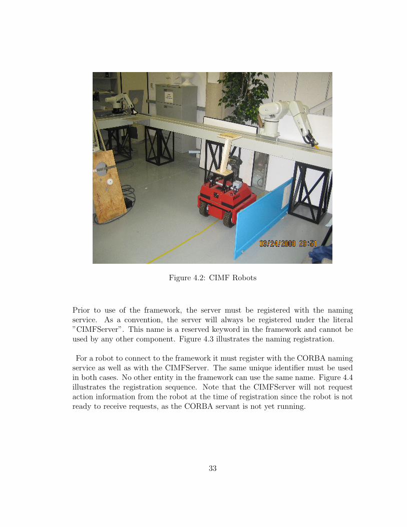
Figure 4.2: CIMF Robots
Prior to use of the framework, the server must be registered with the namingservice. As a convention, the server will always be registered under the literal”CIMFServer”. This name is a reserved keyword in the framework and cannot beused by any other component. Figure 4.3 illustrates the naming registration.
For a robot to connect to the framework it must register with the CORBA namingservice as well as with the CIMFServer. The same unique identifier must be usedin both cases. No other entity in the framework can use the same name. Figure 4.4illustrates the registration sequence. Note that the CIMFServer will not requestaction information from the robot at the time of registration since the robot is notready to receive requests, as the CORBA servant is not yet running.
33

Figure 4.3: Naming Registration
4.2 CIMF Interface Based Interaction
The CIMF interface, shown in Figure 4.5 is an entity that connects to the serverand controls the systems. The interface was designed in order to make the useof the system easier and accessible for non professional end users. Since a majorgoal in this research is to make the framework design generic enough to accom-modate for integrating more modules and entities, the interface was designed toalso serve this purpose. The user can connect to the server by specifying the portnumber and the host address. In our case, the port number is 1111, and the serverCIMF server is running on the same machine. When a robot that complies to theframework protocol connects to the framework, its definition and functionalities areadded to the interface. Figure 4.6 shows how the framework supports both paralleland serial execution. The user can add actions to the action list, where differentcolumns correspond to parallel execution of actions, and different rows in the samecolumn correspond to actions to be executed serially. For the example shown inFigure 4.6, when we press the execute button, Manipulator F3 will start movingto go to location ”b” (assuming manipulator F3 is not initially at location ”b”),and Manipulator F255 will start moving to go to location ”a” at the same time.
34

Figure 4.4: Registration Sequence
More details about the actions and locations shall be presented in the subsequentsections. Once each manipulator accomplishes this task, the next action located inthe next row of each column will start taking place. Both manipulators will closetheir grips, and the system will be ready for new user inputs and commands.
The ”Pick and Place” button is a bit trickier. As a matter of fact, this com-mand will make the system perform a cooperative type of work. Manipulator F3,Manipulator A255, and the ground mini robot will be all involved performing this
35

Figure 4.5: CIMF Interface
task as needed. Scheduling the concurrency in the execution of the actions willbe all taken care of by the server. More detailed description of ”Pick And Place”command will be also presented in subsequent sections.
36

Figure 4.6: CIMF Interface
4.3 Speech Recognition Module
4.3.1 Introduction
The increasing need for more natural human machine interfaces has generated in-tensive research work directed toward designing and implementing natural speechenabled systems. The design of speech applications is no more restricted to onlyspeech recognition and understanding simple commands, but it goes beyond that
37

to getting all the information in the speech signal such as words, meaning and emo-tional state of the user. In fact, emotion recognition that is based on a speech signalis becoming one of the most intensively studied research topics in the domains ofhuman-computer interaction and affective computing as well. Due to many po-tential benefits that may result from correct identification of subjects emotionalcondition, recognition of emotional state is becoming an emerging important areain automated speech analysis. Correct evaluation of human emotion increases theefficiency and friendliness of human-machine interfaces, and allows for monitoringof psychophysiological condition of individuals in many work environments, thusadjusting the type of interaction with the user. However, only speech recognitionwill addressed in this work.
The major problem in speech recognition is that it is very hard to constrain aspeaker when expressing a voice-based request. Therefore, speech recognition sys-tems have to be able to filter out the out of vocabulary words in the users speechutterance, and only extract the necessary information (keywords) related to the ap-plication. The system that spots such specific terms in the user utterance is calleda keyword spotting system. Most state of the art of the keyword spotting systemsrely on a filler model (garbage model) in order to filter out the out of vocabularyuttered words [58, 59]. However, up till now, there is no universal optimal fillermodel that can be used with any automatic speech recognizer (ASR) and handlenatural language. Several researchers have attempted to build reliable and robustmodels, but when using these kind of garbage models, the search space of the speechrecognizer becomes big and the search process takes considerable time.
4.3.2 Overview
Phoneme Recognition
Sounds are made when the breath passes through the vocal cords in our voicebox and causes them to vibrate. The vocal anatomy, shown in Figure 4.7, ofevery speaker is unique; thus making the unique vocalizations of speech sounds.Communication however, is based on commonality of form at the perceptual level.Fortunately, researchers found some characteristics in the speech sounds that canbe efficiently used for the description and classification of words in. They adoptedvarious types of notation to represent the subset of phonetic phenomena that arecrucial for meaning [60].
In human language, a phoneme is the smallest structural unit that distinguishes
38

meaning. They are the primary units that must be first recognized in the speechrecognition process. In fact, the most promising approach to the problem of largevocabulary automatic speech recognition comes to be by implementing a speechrecognizer that works at the phoneme level [61].
In most of the worlds languages, the inventory of phonemes can be split in twobasic classes:
• Consonants : A consonant is a speech sound that is articulated with a com-plete or partial closure of the upper vocal tract that lies above the larynx asshown in Figure 4.7.
• Vowels : In contrast to a consonant that is characterized by constrictions orclosures at some points along the vocal tract, a vowel is a speech sound thatis articulated with a complete open configuration of the vocal tract, thuspreventing any build-up of air pressure above the glottis.
Figure 4.7: Vocal Tract Anatomy
The tongue shape and positioning in the oral cavity do not form a major constric-tion of air flow during vowel articulation. However, variations of tongue placementgive each vowel its distinct character by changing the resonance. The vowel hightrepresents the vertical position of the tongue with respect to either the aperture of
39

the jaw or the roof of the mouth. High vowels, as ”i” and ”u” have tongue posi-tioned high in the mouth, while low vowels, as ”a”, have the tongue positioned lowin the mouth. On the other hand, the horizontal tongue position during the articu-lation of a vowel relative to the back of the mouth is referred as the vowel backness.Front vowels, such as ”i”, have the tongue positioned forward in the mouth, whileback vowels, as ”u”, have it positioned towards the back of the mouth. Other artic-ulatory features are also involved in distinguishing different vowels in a language,such as the roundness of the lips, and whether the air escapes through the noseor not. The major resonances of the oral and pharyngeal cavities for vowels arecalled F1 and F2 - the first and second formants[60], respectively. The acoustics ofvowels can be visualized using spectrograms, which display the acoustic energy ateach frequency, and how this changes with time [61].
On the other hand, the word consonant comes from Latin and means sounding withor sounding together. The idea behind the name comes from the fact that in Latinconsonants don’t sound on their own, but occur only with a nearby vowel. Thisconception of consonants, however, does not reflect the modern linguistic under-standing which defines consonants in terms of vocal tract constriction. Consonants,as opposed to vowels, are characterized by significant constriction or obstruction inthe pharyngeal and/or oral cavities. When the vocal folds vibrate during phonemearticulation, the phoneme is considered voiced, otherwise it is unvoiced. Vowels arevoiced throughout their duration. Some consonants are voiced, others are not [61].Each consonant can be distinguished by several features:
• The manner of articulation is the method that the consonant is articulated,such as nasal (through the nose), stop (complete obstruction of air), or ap-proximant (vowel like).
• The place of articulation is where in the vocal tract the obstruction of theconsonant occurs, and which speech organs are involved.
• The phonation of a consonant is how the vocal cords vibrate during the ar-ticulation.
• The voice onset time (VOT) indicates the timing of the phonation. Aspirationis a feature of VOT.
• The airstream mechanism is how the air moving through the vocal tract ispowered.
• The length is how long the obstruction of a consonant lasts.
40

• The articulatory force is how much muscular energy is involved.
Confidence Measure
When designing a speech application, one has to keep in mind the specific keywordsthat we expect the ASR to spot. Hence a speech grammar package has to be gen-erated. However, this does not mean that the ASR will only spot these keywordsand get rid of everything else. In fact, when the ASR finds a word that is notincluded and defined in the speech grammar, it will automatically wrongly map itto a grammar keyword. In this case, an out of vocabulary word is false mappedto a keyword. Thus, introducing words that are not present in the speech gram-mar causes the ASR to stretch to the limit and hence leading it to cause a lot offalse mapping. For this reason, when we try to speack naturally to the system, theASR output will be containing the correct uttered keywords and also other falselymapped words. So the aim now reduces to finding a way to filter out all thesefalsely mapped keywords. To do that, we will have to rely on a confidence metricto evaluate the degree of correctness for each recognized word. Fortunately, thiscan be done by using the ASR confidence values.
A confidence measure (CM) is a number between 0 and 1 that is applied to speechrecognition output that gives an indication of how confident the ASR is about thecorrectness of the keyword being recognized. A low value of CM (closer to 0 than1) means that the recognized word is most probably an out of vocabulary wordthat was false mapped to a keyword, and hence should be discarded, and a highvalue of CM (closer to 1 than 0) is a good indication that the word being recognizedis indeed an uttered word, and hence should be conserved. Confidence measuresare extremely useful in any speech application that involves a dialogue, becausethey can guide the system towards a more intelligent flow that is faster, easier andless frustrating for the user. In fact, a low degree of confidence is assigned to theoutputs of a recognizer when facing an out-of-vocabulary (OOV) word or some un-clear acoustics that are caused by some background noise that represent a majorsource of recognizer error. Nowadays, much more research work is being dedicatedto finding more reliable measures that are capable to evaluate to a high degree thecorrectness of the speech recognition process, thus increasing the usefulness and in-telligence of an automatic speech recognition system in many practical applications[61].
41

4.3.3 Application Design
Speech synthesis is the artificial production of human speech. A computer systemused for this purpose is called a speech synthesizer, and can be implemented in soft-ware or hardware. A text-to-speech (TTS) system converts normal language textinto speech; other systems render symbolic linguistic representations like phonetictranscriptions into speech.
Synthesized speech can be created by concatenating pieces of recorded speech thatare stored in a database. Systems differ in the size of the stored speech units; asystem that stores phones or diphones provides the largest output range, but maylack clarity. For specific usage domains, the storage of entire words or sentences al-lows for high-quality output. Alternatively, a synthesizer can incorporate a modelof the vocal tract and other human voice characteristics to create a completely”synthetic” voice output.
In the designed speech application, AT&T TTS [62] was used for speech synthesis;and Nuance engine [63] was used in the recognition process. The speech applicationis designed to allow the user to specify the name of the robot and the task he wouldlike the robot to perform in more natural way. The user might decide to specify therobot name and the task name at the same time as in ”I would like manipulatorF3 to go to open the grip please”; or he might just choose to specify them into twodifferent steps instead of only one as shown in Figure 4.8. The user can for examplesay first ”i would like to use manipulator F3 please”, and after ”manipulator F3”being recognized, the user specifies the task name as in ”i would like it to open thegrip if that is feasible”.
When the application start running, the user is prompt to specify the robot nameand the task name. If both of them were specified and successfully recognized withhigh confidence, the user is prompted to confirm what has been recognized. If a pos-itive confirmation is detected, then the system has all the information it needs and isready to communicate with the CIMF server; if a negative confirmation is obtained,the system ignores what has been recognized and reset itself and go back to themain node. However, if only the robot name or the task name gets recognized, theuser is asked to confirm what has been recognized. Negative confirmation takes thesystem to the initial state. In the case of a positive confirmation, the user is askedto specify the missing information. Once being specified and positively confirmed,the system will be ready with all the information needed, and the communicationbetween the speech application and the CIMF server starts taking place. This high
42

Figure 4.8: Recognized Keywords in the Speech Application
level architecture of this process is illustrated in Figure 4.9. ”Robot Name = 0”means that the robot name has not been recognized or confirmed yet, and a valueof one means that successful recognition and confirmation have taken place. Sameapplies to ”Robot Task”.
The three robots described in the previous chapter are involved in this process.The two manipulators and the ground mobile robot. The manipulators are orig-inally called Manipulator F3 and Manipulator A255. Each manipulator has thealias ”Arm”. So when either ”Manipulator F3” or ”Arm F3” gets recognized, thesystem will know that ”Manipulator F3” is the meant robot. On the other hand,the ground robot has more aliases. These aliases are ”IRobot”, ”Mini Robot”,”Ground Robot”, ”Mobile Robot”, ”ATRV Robot”, and ”Red Robot”. Each robotcan perform a set of specific actions:
43

Figure 4.9: Flow Diagram of the Speech Application
Manipulator F3:
• ”Pick” action: The manipulator picks an object from locations ”A”, ”B”, or”D”
• ”Place” action: The manipulator places an object at location ”A”, ”B”, or”D”
• ”Go To Location” action: The manipulator simply goes to location ”A”, ”B”,or ”D”, then wait for another command.
• ”Open Grip” action: The manipulator opens the grip.
• ”Close Grip” action: The manipulator closes the grip.
where the locations map is described in Figure 4.10.
44

Figure 4.10: Locations Map
Manipulator A255:
• ”Pick” action: The manipulator picks an object from locations ”B” or ”C”
• ”Place” action: The manipulator places an object at location ”B” or ”C”
• ”Go To Location” action: The manipulator simply goes to location ”B” or”C”, then wait for another command.
• ”Open Grip” action: The manipulator opens the grip.
• ”Close Grip” action: The manipulator closes the grip.
Ground Robot:
• ”Go To Location” action: The mobile robot can move to locations ”D” or”E”.
45

Note that manipulator F3 and manipulator A255 share the same set of actionsexcept that they both work on different locations. Manipulator F3 covers loca-tions ”A”, ”B”, and ”D” while manipulator ”A255” covers locations ”B”, and ”C”.Finally, the ground robot covers locations ”D” and ”E”. As we notice, the threerobots have their own specific actions to perform; so when the user perform theaction ”Go To Location” on manipulator F3, and he specifies the location to be”D”, only manipulator F3 will perform this action and the remaining robots stayin their positions. On the other hand, the framework supports also some sort ofcooperative work that can involve as many robots as needed to perform the action.One action that requires such cooperation is the ”Pick And Place” command.
Imagine the scenario where we need to ”Pick and Place” an object from loca-tion ”C” to location ”F”. The system will automatically perform the followingactions. First, manipulator A255 will ”Go To Location” ”C”, ”Open Grip”, ”Pick”the object, and then ”Go To Location” ”B”. At the same time, manipulator F3will ”Go To Location” ”B”, and the ground robot will ”Go To Location” ”D”.Once the manipulator A255 reaches location ”B”, it shall ”Place” the object, thenimmediately afterward, manipulator F3 will ”Open Grip”, ”Pick” the object, and”Go To Location” ”D”. Figure 4.11 shows the cooperative work between the twomanipulator at this stage. Once location ”D” is reached, the manipulator F3 shall
Figure 4.11: Cooperation Between Manipulator A255 and Manipulator F3
”Place” the object on top of the mobile robot which is already waiting at location
46

”D”. If the mobile robot is not there yet, the manipulator keeps waiting for it, andthen place the load on it. Then, the mobile robot shall ”Go To Location E”.
4.3.4 Confidence Threshold Design
The choice of confidence threshold in the voice application is very critical. As wementioned before, all recognition with a confidence value lower than this thresholdwill be rejected, and considered to be garbage words falsely mapped to in gram-mar keywords. Underestimating this threshold will increase the false accept rate,and allow background noise and garbage words to be falsely mapped to keywords.Overestimating this threshold, on the other hand, will increase the false reject rate;thus a proper design of this threshold is crucial.
Another thing that one has to keep in mind, is that different keywords can havedifferent confidence values when being recognized by the ASR, even when playedby the same TTS. This is because the length of the keyword largely affect its confi-dence value. In fact, longer keywords tend to have a higher confidence values thanshort ones. It is also important to note that each node has its own set of keywords,and it is important to generate a threshold for each one of them independently ofthe others.
In our application, the system retrieve all the keywords that correspond to a spe-cific node, and then the TTS plays these keywords and saves the confidence valuethat corresponds to the recognition of each one of them. Then the lowest value isrecorded as ”Temp1”. In addition, and in order to accommodate for the backgroundnoises and garbage words, another set of prerecorded noises and out of vocabularywords are also played to the ASR, and the confidence values are saved. the highestvalue is recoded as ”Temp2”. Now,two situation arise. If ”Temp1” is greater than”Temp2”, then a middle way between the two values is chosen as a threshold asshown in 4.1.
Temp1 > Temp2⇒ Threshold = (Temp1 + Temp2)/2 (4.1)
On the other hand, if ”Temp1” is smaller or equal to ”Temp2”, then the system givesa warning message to the user, asking him/her to remove or modify the keywordthat is causing this problem (which is the keyword that got the lowest confidencevalue), and a threshold value equal to ”Temp1” is temporarily chosen as illustratedin 4.2.
47

Temp1 ≤ Temp2⇒ Threshold = Temp1 (4.2)
Note that without implementing this confidence threshold mechanism, every sin-gle garbage words or noise will be falsemapped to a keywords. So imagine thescenario where we test the system with 10 in grammar words, and 90 out of vocab-ulary words, a recognition accuracy of 10% at most will be obtained; but with ourthreshold mechanism, accuracies can reach 90’s very easily for small and mediumsized set of keywords.
4.4 Gesture Recognition and Fusion Modules
In this section, the implementation of a gesture recognition module is illustrated.Then a fusion module that combines both the speech recognition module and thegesture recognition module is presented. This type of gesture-speech multimodalsystem is the most common type of multimodal systems, and is used to removethe ambiguity that may result when one of the fused modules provides missinginformation or no information at all.
4.4.1 Introduction
Gestures are expressive, meaningful body motions. They represents physical move-ments of the fingers, hands, arms, head, face, or body that have the intent to conveyinformation or interact with the environment. Gesture recognition is the process bywhich gestures made by the user are make known to the system. Messages can beexpressed through gesture in many ways. For example, an emotion such as sadnesscan be communicated through facial expression, a lowered head position, relaxedmuscles, and lethargic movement. Similarly, a gesture to indicate Stop! can besimply a raised hand with the palm facing forward, or an exaggerated waving ofboth hands above the head. In general, there exists a many-to-one mapping fromgesture to concept.
Gestures can be static, where the user assumes a certain pose or configuration,or dynamic, defined by movement. McNeill [64] defines three phases of a dynamicgesture: pre-stroke, stroke, and post-stroke. Some gestures have both static anddynamic elements, where the pose is important in one or more of the gesture phases;
48
this is particularly relevant in sign languages. When gestures are produced contin-uously, each gesture is affected by the gesture that preceded it, and possibly by thegesture that follows it. Static gesture, or pose, recognition can be accomplishedby a straightforward implementation using template matching, geometric featureclassification, neural networks, or other standard pattern recognition techniquesto classify pose. Dynamic gesture recognition, however, requires consideration oftemporal events. This is typically accomplished through the use of techniquessuch as time-compressing templates, dynamic time warping, hidden Markov mod-els (HMMs), and Bayesian networks.
4.4.2 Gesture Recognition Module
The Gesture Recognition Module (GRM) used is based on the HandVu package[65]. The implemented system depends on HandVu Beta3.
HandVu can use the input of a typical webcam. First, it attempts to detect ahand, then it tries to track it and recognize one of a limited set of basic gestures.The recognized gestures are referred to as: closed, Lback, open, victory, Lpalm, andsidepoint. These sets of gestures are illustrated in Figure 4.12 and 4.13. HandVuprovides the convenient functionality of making its recognition results available ona TCP/IP port.
When the program is started, it starts the server and opens up a window showingthe webcam’s real time capture accompanied with gesture recognition information.The gesture server runs on port 7045 and outputs lines that follow a specific gestureevent protocol.
4.4.3 Type Feature Structures
Typed Feature Structures (TFSes) are a key construct in the implemented mul-timodal interaction system. The architecture of our speech-gesture multimodalsystem is illustrated in Figure 4.14. The Gesture Interpretation Module and theSpeech Interpretation Module, both produce TFSes to represent their interpreta-tion of any useful recognized gesture or speech. The structure of the TFSes thenmakes it possible for the Fusion Module to take TFSes from multiple sources andattempt to combine them together to produce TFSes that fully specify certainmethod invokations to send to the Centralized Robot Server.
49

Figure 4.12: HandVu Gestures
Each TFS represents an invokable function or some part of it. A distinction ismade between an ExecutableTFS which specifies what function to invoke, and aSupportiveTFS which specifies only possible parameter values. To explain this con-cept, let’s imagine that there is a function Move that takes one parameter to specifywhich direction to move in. A TFS t1 may be defined as follows:
• t1 = ExecutableTFS(Move, [OperationArg(”Direction”, ”Forward”)])
What this means is that t1 represents an invocation of Move, where the first pa-rameter is set to ”Forward”. One could also define a TFS t2 as follows:
• t2 = ExecutableTFS(Move, [OperationArg(”Direction”)])
This TFS is referring to the function Move that takes one parameter of the typeDirection. However, it does not provide a value for the parameter. This means
50

Figure 4.13: HandVu Gestures
that we do not have all the necessary information to actually make the functioncall. Lastly, one could define a SupportiveTFS t3 as follows:
• t3 = SupportiveTFS([OperationArg(”Direction”, ”Forward”)])
Note that this TFS simply specifies a possible function argument and its value.Clearly, based on this TFS alone, one cannot invoke any functions as none arespecified. The critical point to see here is that although t2 and t3, on their own,may not fully specify all the necessary information to invoke Move, together they doprovide a full specification of a Move invokation. That is, t2 provides the fact thata Move method is to be invoked, whereas t3 provides the value for the Directionparameter. This unification between two TFSes can be carried out by the unifyWithmethod supported by the ExecutableTFS and SupportiveTFS classes. Any numberof TFSes could be unified together.
51

Figure 4.14: Interaction Overview of System’s Components
4.4.4 Gesture Interpretation Module
The Gesture Interpretation Module (GIM) listens to the port where the GestureRecognition Module writes its gesture recognition results. It interprets the outputof Gesture Recognition Module and produces corresponding Typed Feature Struc-tures when appropriate. Any produced TFSes are sent to the Fusion Module, which
52

also gets the TFSes produced by the speech interpretation modules.
The meat of the GIM is in the method ”run”. Essentially, ”run” just continuouslylistens to the TCP/IP port and parses every line that it receives. Each line followsthe gesture event protocol [HV4] and so ”run” can extract from each line what pos-ture was recognized if any. Then, if a posture, such as ’victory’ is detected, ”run”calls a corresponding method specified by a mapping in the dictionary variableposture2tfs. The called method will be either toggleTracking or cancelTracking.toggleTracking starts or ends the tracking of the hand. If the toggling ends thetracking, then the hand’s current location is compared to its location upon startof tracking. The result of this comparison may determine that the user has movedhis/her hand up, down, left, right, or not moved it at all. Each one of those resultsmay have a corresponding TFS specified as parameters to toggleTracking. TheGIM sends the identified TFS as an argument to the Fusion Module’s ”accept”method. Thus, effectively, one can specify a certain TFS by making a certain sign,such as ’victory’, making a fist, moving the hand in some direction, then makingthe same sign again (’victory’ in this case). The first ’victory’ starts the tracking.The second ’victory’ ends the tracking. If the hand is moved in a different directionor a different sign is used to toggle the tracking then a different TFS will result.cancelTracking simply cancels the tracking if it had started but not toggled againto end it.
4.4.5 Speech Interpretation Module
The Speech Interpretation Module (SIM) works very similarly to the Gesture Inter-pretation Module and thus its high level description is almost identical. The SIMlistens to the port where the Speech Recognition Module writes its speech recogni-tion results. It interprets the output of Speech Recognition Module and producescorresponding Typed Feature Structures when appropriate. Any produced TFSesare sent to the Fusion Module, which also gets the TFSes produced by the GestureInterpretation Modules.
The meat of the SIM is in the method ”run”. Essentially, ”run” just continu-ously listens to the TCP/IP port written to by the Speech Recognition Module.It parses every line that it receives. Each new received line is expected to simplyhave a string identifying a particular operation. If the string is from a predefinedlist, such as ”performAction Manipulator F3 Pick”, is detected, ”run” determinesa corresponding TFS and sends it as an argument to the Fusion Module’s ”ac-cept” method. The specification of the Typed Feature Structures corresponding to
53
each string are specified in a dictionary stored as an instance variable kw2tfs for aSpeechInterpreter object.
4.4.6 Fusion Module
The Fusion Module has only one public method, ”accept”. As mentioned earlier,”accept” accompanied by its TFS parameter is invoked by the Gesture Interpreta-tion Module and the Speech Interpretation Module. Thus, all interpreted TFSesultimately go to the Fusion Module via the ”accept” method.
Each time a new TFS arrives, ”accept” stores its arrival time. The ”accept” methodinserts the input TFSes into a queue. However, upon each invokation, ”accept” re-moves from the queue any TFSes that had been in it for some predefined period oftime STALENESSTIME or longer.
Upon receiving a new TFS, ”accept” checks whether the given TFS specifies afunction as well as a value for all of its parameters. If this is the case, then ”ac-cept” has all the necessary information to invoke the TFS’ corresponding functionand does in fact do so. Note that since the TFS can be executed immediately uponarrival, there is no need to add it to the TFS queue.
The other case is when the given TFS does not provide all the necessary invokationinformation, such as what function to call or the parameter values. In this case,accept first attempts to find another TFS in the queue that can be unified with thenew one. Unification was explained in the Typed Feature Structure section earlier.If the given TFS can be unified with another one in the queue, then the two areunified. The result of the unification may be a fully specified TFS in which casethe corresponding function invokation is made and neither of the unified TFSesare left in the queue. However, a unification of two TFSes may produce a stillunderspecified TFS. In such a case, only the TFS resulting from the unification isleft int the queue and another iteration is made through the queue to see if thisnew TFS can go through further unification. Lastly, in the case that the given TFSdoes not have all the necessary information for invokation, nor can be unified withanother TFS in the queue, then nothing is done beyond inserting it into the queue.Of course, the inserted TFS may later be involved in a unification with anotherTFS. The overall system architecture is summarized in Figure 4.14
54

4.5 Framework Evaluation
Quality attributes of large software and hardware systems are determined by thesystem architecture. In fact, the achievement of these attributes such as perfor-mance, sensitivity, availability and modifiability tend to depend more on the over-all system’s architecture rather than on code specifics such as the programminglanguage, algorithms, data structures, testing, and so on, that are less crucial to asystems success. Thus, it is in our interest to try and determine, whether a sys-tem/framework is destined to satisfy its desired qualities. In reality, the attributesof a system interact, meaning that ”performance sometimes affect modifiability.Availability impacts safety. Security affects performance. Everything affects cost.And so forth. Therefore, every design, in any discipline, involves tradeoffs thatarise from architectural elements that are affected by multiple attributes” [66].
Our presented framework was implemented and evaluated based on the Architec-ture Tradeoff Analysis Method (ATAM) [67]. This method involves the followingmain steps: scenarios collection, requirement/constraints/environment collection,architectural views description, attribute analysis, sensitivities identification, andtradeoffs identification as shown in Figure 4.15.
First, an initial set of scenarios and requirements are collected. These requirementsand design principles generate tentative candidate architectures and constrain thedesign possibilities which are also affected by previous successes and failures ofother designed projects and architectures. In fact, an essential task of a designer isto choose the architecture that will make the system behavior as close as possibleto the proposed requirements within the present constraints and limitations [66].Then, each quality attribute must be analyzed individually and independently withrespect to each candidate architecture. Thus, statements that describe the systembehavior with respect to each particular attribute will be produced. Examples ofsuch statement are: ”the system’s processing time on average is 600 ms”, ”thehardware cost is around 30,000 dollars”, ”the system requires at least five servers,hence increasing the risk of being attack”, and so on.
After such evaluations take place, the critique step arises: tradeoff points and ele-ments that affect more than one attributes are recorded and well studied to refineor change the models, architectures, or even the requirements, and then re-evaluatethe system again [66].
In our proposed framework, quality attributes such as cost, security, reliability,
55

flexibility, maintainability, speed and safety are highly addressed. The frameworkis intended to be flexible enough to allow all kind of users to manipulate it locallyand remotely. It is intended to allow easy integration of multiple modules suchas a speech recognition application, web application, gesture recognition applica-tion, and so on, and easy addition of new hardware and tasks that are supportedby these hardware. For these reasons, two IDL files (CIMFRobot.idl and CIMF-Server.idl) were implemented to define some protocol to facilitate communicationbetween entities, and to also define the minimal functionality that must be providedby different entities and modules in order to be able to integrate into the framework.
The framework was tested on three hardware entities (2 manipulators and oneground robot as described in previous chapters), and three major interfaces (stan-dard computer interface, speech recognition based application, and gesture recog-nition based application). Each interface had its own server to handle its requests,and process its inputs. Doing this is important because one server would decreasethe speed of the system and causes more delays especially when speech, gesture, orgesture-speech recognition takes place. On the other hand, increasing the numberof servers was also a tradeoff point with respect to our architecture, as securitymight vary inversely to the number of servers because the system might containmore potential points of attack.
The framework is implemented to support multiple number of robotics entities,but that does not mean that we can add infinite number of hardware, and expectthe system to behave perfectly. So far, only three robots successfully connects tothe system; more hardware entities shall be added in the future, but that is alsoanother tradeoff point between both cost and extensive testing, as each of theseentities cost tens of thousands of dollars.
Safety was also addressed especially that we allow remote control of the systemand hardware connected to the system. This is why the lab is equipped with asurveillance camera that can be accessed remotely, and allows users to see what isin reality happening in the lab. Each interface is equipped with the potential ofenabling the emergency stops in each of the involved robotics entities to furtherimprove the safety feature.
Another tradeoff emerges between increasing the number of integrated modulesand hardware in the system and the required number of people needed to maintainthe system. More people will be needed to maintain the system as more entitiesget integrated into the framework.
56
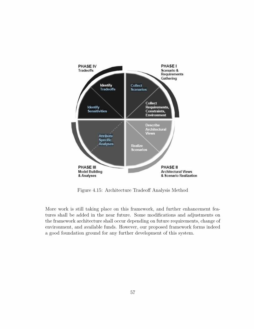
Figure 4.15: Architecture Tradeoff Analysis Method
More work is still taking place on this framework, and further enhancement fea-tures shall be added in the near future. Some modifications and adjustments onthe framework architecture shall occur depending on future requirements, change ofenvironment, and available funds. However, our proposed framework forms indeeda good foundation ground for any further development of this system.
57

Chapter 5
Face Recognition and Security
5.1 Overview on Biometrics
Biometric recognition refers to automatic recognition of individuals based on somespecific physiological and/or behavioral features. The use of biometrics has grownvery fast for the last decade; they are mostly used for identification systems im-plemented to provide a more secure environment, and authenticate the identity ofall who can pass, minimizing the chance of letting unauthorized persons through(false accept), or of stopping people who are authorized to pass (false reject). Atthe same time, the system should be fast enough to deal with possible real timetraffics, as at physical checkpoints.
Photographs and fingerprints have been used for a century, and recently some moreadvanced biometrics have been used, such as measuring the geometry of the palmor hand; recognizing the pattern of blood vessels in a retina or the flecks of color inan iris; or making the pattern in a person’s DNA; as well as recognizing voices orfaces, or the way people walk. Biometrics systems are usually used to accomplishone of two related objectives: identification or verification [68]. Identification refersto the process of trying to find a match between a query biometric sample and onestored in the database. For instance, to obtain access to a restricted area, one maygo through an iris scan. A corresponding template describing the discriminatingfeatures is built for the scanned iris. Then the new template is compared to allthose stored in the database. One is then granted or denied access depending onthe existence of a database template similar to the query template. Verification, onthe other hand, refers to the process of checking whether a query biometric samplebelongs to a claimed identity. For instance, one may have to enter an ID number
58
or use a particular card, then have one’s iris scanned. The biometric system thenhas to only check whether the constructed query template is similar enough to thedatabase template associated with the given ID number or card.
There are a wide variety of applications for biometrics in existence today. Of course,these applications have sprung up because of the benefits biometrics provides as anidentification solution. Depending on the application, a particular benefit is usuallyemphasized, such as security, convenience, or privacy.
Security
The uniqueness of biometric signals and the difficulty in forging them makes bio-metrics an attractive solution for enhancing security. The Republic of the Maldives,with the support of BioLink, introduced passports that come with microchips stor-ing fingerprint and face templates. This technology allows for quick and reliableidentification of citizens [69]. Mexico City International Airport installed Bio-scrypt’s V-Smart authentication system to provide access control to high-securityareas of its terminals. The system requires use of a smart card that stores one’sfingerprint template [70].
Convenience
Biometrics provide a very convenient solution that allows one to quickly authenti-cate into a system without necessarily having to carry anything, take the time totype anything, nor remember any secret strings. This convenience factor has at-tracted many manufacturers. Axxis Biometrics makes fingerprint-based door locks,such as their 1Touch [71]. Also, mainstream Lenovo notebooks, such as the R Se-ries come with an integrated fingerprint reader that lets users simply swipe theirfinger, rather than enter passwords to log in [72]. NCR, on the other hand, providespoint-of-sale biometric terminals used to quickly authenticate sports bar employeesto enter orders. Columbia’s Bancafe Bank incorporated NCR’s fingerprint readersacross all of its ATM network, so that users no longer need to carry an ATM cardto make transactions [73].
Privacy Enhancement
Biometrics can be used as unique identifiers without revealing any personal infor-mation about the person they are identifying. Opposite to what many believe,
59

biometrics could in fact enhance privacy. Thus, biometrics could be the ideal so-lution for social benefit programs where it is important to keep track of usage;but privacy is a major concern. On the Pakistan-Afghanistan border, the UnitedNations High Commission on Refugees (UNHCR) uses an iris recognition solutionto ensure that each Afghani refugee obtains only one refugee package. To obtain apackage, refugees have to authenticate via the iris recognition system. If they arealready in the database, then they are identified as having already received theirpackage. If they are not in the database, then they are added to it and are givena package. The biometric database stores nothing but iris templates that are notlinked with any personal information to the refugees [74].
In this research, Face recognition was used for user identification due to its ef-fectiveness and ease of implementation.
5.2 Face Recognition: Definition
Facial recognition is usually thought of as the primary way in which people recog-nize one another. After all, given a search through one’s wallet, it becomes clearthat identification based on facial recognition is used by many organizations, suchas universities, government agencies, and banks, although the recognition is usuallycarried out by a human. Many of these organizations will, of course, have thesephotos stored in large databases making many commercial and law-enforcementapplications feasible given a reliable facial recognition system. Additionally, facialimages of a person can usually be collected without necessarily requiring much co-operation from that person. Thus, it is no surprise that facial recognition is a keypart of the DARPA-funded Human ID at a Distance Project aimed at developingthe technology to identify terrorists from a distance [13].
There are many approaches that exist for tackling face recognition. Some of theseapproaches use the whole face as raw input, such as eigenfaces and fisherfaces,which are based on principal component analysis. Other approaches depend onextracting and matching certain features from the face, such the mouth and eyes.Lastly, some approaches are a mix of the two using data from the whole face aswell as specific features to carry out the recognition. In the following section, theimplementation of our face recognition module is presented.
60

5.3 System Architecture
As shown in Figure 5.1, the face authentication module consists of three major com-ponents: Preprocessing, Recognition and Voting. Its inputs are n images (frames)captured by the camera (n is currently set to 10). Preprocessing and Recognitionare performed on each image to produce a recognition result. Eventually, all therecognition results are combined to give an authentication decision using a votingscheme.
Figure 5.1: System Architecture
5.4 Image Preprocessing
Image preprocessing is used to get rid of the background from the input imagesand make them more comparable. It is performed in three steps:
• Histogram equalization
61

• Face alignment
• Normalization
5.4.1 Histogram Equalization
Histogram equalization enhances the contrast of images by transforming the valuesin an intensity image so that the histogram of the output image approximatelymatches a specified histogram. More precisely, this method usually increases thelocal contrast of many images, especially when the usable data of the image is rep-resented by close contrast values. Through this adjustment, the intensities can bebetter distributed on the histogram. This allows for areas of lower local contrast togain a higher contrast without affecting the global contrast. Histogram equalizationaccomplishes this by effectively spreading out the most frequent intensity values.This method is useful in images with backgrounds and foregrounds that are bothbright or both dark. Its input and output are compared in Figure 5.2.
Figure 5.2: Histogram Equalization
5.4.2 Face Alignment
The aim of Face Alignment is to find the location and orientation of face area inthe image. Here we implemented it using template matching algorithm, namely wefirst train an eye-nose template and then search for the best match in a new image.
62

Template Training
To extract the template, we first manually label the landmark points on a set oftraining images, as shown in Figure 5.3. According to these three landmarks, theeye-nose areas in the training images are extracted, and we use their average as thetemplate as shown in Figure 5.4.
Figure 5.3: Histogram Equalization
Figure 5.4: Eye-Nose Template
Template Matching
Given a new image, the algorithm searches though different location (x,y) andorientation θ to minimize the cost function 5.1
D(x, y, θ) = Dmatch(x, y, θ) + w.Dsym(x, y, θ) (5.1)
where the first term of the equation represents the difference between the currentarea and the template, and the second term represents the asymmetry of the currentarea, namely the difference between the left half and the right half. Here bothdifferences are defined as the variance. w is the weight of asymmetry penalty, here
63

we set it to be 0.2. Typical input and output are shown in Figure 5.5. We can see,the face in the input is not upright and the algorithm fixes this by rotating it forapproximately 15 degrees counterclockwise.
Figure 5.5: Template Matching Results
5.4.3 Normalization
To make the images more comparable and also to reduce their size, normalizationis performed based on the alignment result. The aligned face areas are chopped tohave the same size as shown in Figure 5.6, and these will be used for the input forrecognition.
5.5 Recognition
Face recognition is the core of this module. It gives the name of person in theimage, or ”No Match” if it can not recognize it. In this system, face recognition isimplemented using Canonical Correlation Analysis (CCA) [75]. A canonical corre-lation is the correlation of two canonical (latent) variables, one representing a setof independent variables, the other a set of dependent variables. Each set may beconsidered a latent variable based on measured indicator variables in its set. Thecanonical correlation is optimized such that the linear correlation between the twolatent variables is maximized. Whereas multiple regression is used for many-to-onerelationships, canonical correlation is used for many-to-many relationships. Theremay be more than one such linear correlation relating the two sets of variables, witheach such correlation representing a different dimension by which the independent
64

Figure 5.6: Normalized Faces
set of variables is related to the dependent set. The purpose of canonical correlationis to explain the relation of the two sets of variables, not to model the individualvariables. For each canonical variate we can also assess how strongly it is related tomeasured variables in its own set, or the set for the other canonical variate. Wilks’slambda is commonly used to test the significance of canonical correlation.
CCA attempts to represent a face by a lower dimensional vector, known as CCAcoefficient, which is highly related to the identity of the person. To do this, it triesto maximize the correlation between the variance of the faces a = wTx x and thevariance of the identity label b = wTy y in the training set as shown in equation 5.2.
p(x, y;wx, wy) =wTxXY
Twy√wTxXX
Twx.√wTy Y Y
Twy(5.2)
65

To handle the nonlinear cases, Kernel technique is employed. The optimization canbe formalized as shown in equation 5.3.
ρ(φ(x), y;wφ(x), wy) =wTφ(x)φ(x)Y Twy√
wTφ(x)φ(x)φ(x)Twφ(x).√wTy Y Y
Twy(5.3)
It has been shown [1] this can be converted into a generalized eigen problem asshown in equation 5.4
KY T (Y Y T )−1Y Kαφ(x) = λ2KKαφ(x) (5.4)
Solving equation 5.3 gives the CCA coefficient, which is a lower dimensional repre-sentation of the face image shown in 5.5. The red circles represent the three knownmembers respectively. When a new image is given, the algorithm finds its corre-sponding point in the CCA space (the blue cross in Figure 5.7), and recognition isperformed according to the distances in the CCA space: the distances between thenew point and the red circles are computed (as shown in Figure 5.8), if the distanceto the nearest circle, d, is smaller than a preset threshold, D, the new image isconsidered to belong to this member; otherwise output ”No Match”. For example,for the image shown in 5.8, its nearest is member 1 (Jamil), and the distance issmall so we recognize it as Jamil.
5.6 Voting and Threshold Decisions
In real-time recognition, due to the influence of other factors, such as illumination,head pose, facial expression and so on, the recognition result on a single imageis not very robust. To overcome this problem, face recognition is performed on nsnapshots of the video input, and the authentication result is generated by combin-ing the recognition outputs. Here we use a voting scheme: each frame either votesto a member or abstains according to its recognition output; a member wins if hegets more than kn votes, if no one wins the system outputs ”No Match” as the finalresult. In general, using large n gives better accuracy, but longer execution time,therefore a tradeoff must take place in here as well; k controls the working positionon the ROC curve: small k gives small False Negative Rate but large False PositiveRate and vice versa.
In our system, n is set to 10 and k is set to 0.6. The reason we decided to take morethan just one or two frames is to benefit from the advantage of moltimodality to
66

Figure 5.7: CCA Coefficients
Figure 5.8: Input Image and Distances in CCA Space
67

overcome the problem that illumination, head pose, facial expression, among otherfactors, might create, and largely affect the recognition result. Add to this, the factthat the camera used for this research is a standard low resolution webcam. There-fore, face recognition is performed on n snapshots of the video input. Results showsthat for n = 1; recognition accuracy was 78 %. For n=5, it went up to 87%, and forn = 10, accuracy achieved a 93%. Higher number of frames achieved slightly higheraccuracy (95% for 20 frames). Therefore, a threshold of 10 frames was chosen as atradeoff point between the accuracy on one hand, and keeping the head of the userbeing authenticated steady for longer time, along with the processing time, on theother hand. Note that results were obtained on only a small set of 5 people whichare the graduate students that have current access to the CIM lab at University ofWaterloo.
68

Chapter 6
Conclusion and Future Work
Human-Computer/Machine Interaction is a sociotechnological discipline that bringsthe power of computer and communication systems to people in ways and formsthat are both accessible and useful in our working, learning, communicating, andrecreational lives with the mean of technologies such as the graphical user interface,virtual environments, speech recognition, gesture recognition, multimedia presen-tation, and cognitive models of human learning and understanding.
The main objective of this research was to implement an intelligent generic frame-work for our manufacturing cell that allows users to integrate easily different mod-ules and robots into the framework. For this purpose, a protocol has been devisedto facilitate standardized communication between all entities of the framework.Thus, all entities must comply with this protocol to guarantee correct operation.A speech recognition module, and a gesture recognition modules were separatelyimplemented and integrated into to the framework, hence enabling system controlusing natural language commands and/or some predefined gestures. The systemcan also be accessed remotely. Safety features were also added by allowing onlyauthenticated people to access the framework. Face recognition was used for thispurpose, and depending on the identity of the person, different levels of access tosystem are enabled, and different features are provided.
Future work can take place on the framework and its integrated modules. Thegesture recognition module can be further enhanced by enlarging the set of ges-tures that can be recognized. Further work can even focus on 3D recognition ofgestures, and hence someone can recognize if a hand is pointing to something atsome time. This might be very helpful in removing ”ambiguity” when the user says
69
for example ”I want this to go to to location b”. ”This” is very ambiguous, but theuser could have been pointing to one of the manipulators when he said ”this”, andhence advanced gesture recognition techniques can be used to recognize the objectbeing pointed to when ”this” was uttered, and therefore removing fuzziness fromthe expression.
Further improvements can be also applied to the speech recognition module. In-stead of only relying on the confidence measure technique, keyword spotting systemsthat rely on advanced filler models (garbage models) in order to filter out the outof vocabulary uttered words can be addressed. Unfortunately, up to now, thereis no universal optimal filler model that can be used with any automatic speechrecognizer (ASR) and handle natural language. Several researchers have attemptedto build reliable and robust models, but when using these kind of garbage models,the search space of the speech recognizer becomes big and the search process takesconsiderable time.
70

Bibliography
[1] J. Abou Saleh F. Karray, M. Alemzadeh and M. N. Arab. Human-computerinteraction: Overview on state of the art. International Journal on SmartSensing and Intelligent Systems, 1(1):137 – 159, March, 2008.
[2] B. A. Myers. A brief history of human-computer interaction technology. ACM:Assiciation for Computing Machinery, 5:44–54, March/April 1998.
[3] J. Carey D. Teeni and P. Zhang. Human Computer Interaction: DevelopingEffective Organizational Information Systems. John Wiley and Sons, Hoboken,2007.
[4] B. Shneiderman and C. Plaisant. Designing the User Interface: Strategiesfor Effective Human-Computer Interaction. Pearson/Addison-Wesley, Boston,2004.
[5] J. Nielsen. Usability Engineering. Morgan Kaufman, San Francisco, 1994.
[6] P. Zhang D. Teeni and D. Galletta. Human-Computer Interaction and Man-agement Information Systems: Foundations. M.E. Sharpe, Armonk, 2006.
[7] A. Chapanis. Machine Engineering. Wadsworth, Belmont, 1965.
[8] D. Norman D. Norman and S. Draper. User Centered Design: New Perspectiveon Human-Computer Interaction. Lawrence Erlbaum, Hillsdale, 1986.
[9] R.W. Picard. ch phone recognition, purdue university, west lafayette, usa.MIT Press, Cambridge, 1997.
[10] T.K. Landauer J.S. Greenstein, M.G. Helander and P. Prabhu. Handbook ofHuman-Computer Interaction. Elsevier Science, Amsterdam, 1997.
[11] B.A. Myers. A brief history of human-computer interaction technology. ACMinteractions, 5(2):44–54, 1998.
71

[12] [10] B. Shneiderman. Designing the User Interface: Strategies for EffectiveHuman-Computer Interaction. Addison Wesley Longman, Reading, 1998.
[13] A. Murata. An experimental evaluation of mouse, joystick, joycard, lightpen,trackball and touchscreen for pointing - basic study on human interface design.In Proceedings of the Fourth International Conference on Human-ComputerInteraction, pages 123–127, 1991.
[14] L.R. Rabiner. Fundamentals of Speech Recognition. Prentice Hall, EnglewoodCliffs, 1993.
[15] D. Nahamoo J.A. Jacko C.M. Karat, J. Vergo and A. Sears. The Human-Computer Interaction Handbook: Fundamentals, Evolving Technologies, andEmerging Application. Lawrence Erlbaum Associates, Mahwah, 2003.
[16] G. Robles-De-La-Torre. The importance of the sense of touch in virtual andreal environments. IEEE Multimedia, Special issue on Haptic User Interfacesfor Multimedia Systems, 13(3):24–30, 2006.
[17] M. Cruz-Hernandez D. Grant V. Hayward, O.R. Astley and G. Robles-De-La-Torre. Haptic interfaces and devices. Sensor Review, 24(1):16–29, 2004.
[18] J. Vince. Introduction to Virtual Reality. Springer, London, 2004.
[19] W. Barfield and T. Caudell. Fundamentals of Wearable Computers and Aug-mented Reality. Lawrence Erlbaum Associates, Mahwah, 2001.
[20] M.D. Yacoub. Wireless technology: Protocols, standards, and techniques. CRCPress, London, 2002.
[21] K. McMenemy and S. Ferguson. A Hitchhikers Guide to Virtual Reality. A KPeters, Wellesley, 2007.
[22] Global positioning system. Home page http://www.gps.gov/.
[23] T.L. Williams S.G. Burnay and C.H. Jones. Applications of Thermal Imaging.A. Hilger, Bristol, 1988.
[24] P. Hong J. Y. Chai and M. X. Zhou. A probabilistic approach to referenceresolution in multimodal user interfaces. In Proceedings of the 9th InternationalConference on Intelligent User Interfaces, Funchal, Madeira, Portugal, pages70–77, 2004.
[25] E.A. Bretz. When work is fun and games. IEEE Spectrum, 39(12):50–50, 2002.
72

[26] A. Garg-L. Chen I. Cohen, N. Sebe and T.S. Huang. Facial expression recog-nition from video sequences: temporal and static modeling. Computer Visionand Image Understanding, 91(1-2):160–187, 2003.
[27] B. Fasel and J. Luettin. Automatic facial expression analysis: a survey. PatternRecognition, 36:259–275, 2003.
[28] M. Pantic and L.J.M. Rothkrantz. Automatic analysis of facial expressions:the state of the art. IEEE Transactions on PAMI, 22(12):1424–1445, 2000.
[29] D.M. Gavrila. The visual analysis of human movement: a survey. ComputerVision and Image Understanding, 73(1):82–98, 1999.
[30] J.K. Aggarwal and Q. Cai. Human motion analysis: a review. ComputerVision and Image Understanding, 73(3):428–440, 1999.
[31] S. Kettebekov and R. Sharma. Understanding gestures in multimodal humancomputer interaction. International Journal on Artificial Intelligence Tools,9(2):205–223, 2000.
[32] Y. Wu, R. Gherbi-S. Gibet J. Richardson T. Huang, A. Braffort, and D. Teil.Gesture-based communication in human-computer interaction. Lecture Notesin Artificial Intelligence, Springer-Verlag, Berlin/Heidelberg, 1739, 1999.
[33] K. Sato T. Kirishima and K. Chihara. Real-time gesture recognition by learn-ing and selective control of visual interest points. IEEE Transactions on PAMI,27(3):351–364, 2005.
[34] L.E. Sibert and R.J.K. Jacob. Evaluation of eye gaze interaction. In Conferenceof Human-Factors in Computing Systems, pages 281–288, 2000.
[35] K. Nagel-Q. Tran I. Essa G. Abowd R. Ruddaraju, A. Haro and E. Mynatt.Perceptual user interfaces using vision-based eye tracking. In Proceedings ofthe 5th International Conference on Multimodal Interfaces, Vancouver, pages227–233, 2003.
[36] A.T. Duchowski. A breadth-first survey of eye tracking applications. BehaviorResearch Methods, Instruments, and Computers, 34(4):455–470, 2002.
[37] E. Vatikiotis-Bateson P. Rubin and C. Benoit. Special issue on audio-visualspeech processing. Speech Communication, 26:1–2, 1998.
[38] J.P. Campbell Jr. Speaker recognition: a tutorial. Proceedings of IEEE,85(9):1437–1462, 1997.
73

[39] P.Y. Oudeyer. The production and recognition of emotions in speech: fea-tures and algorithms. International Journal of Human-Computer Studies,59(1-2):157–183, 2003.
[40] L.S. Chen. Joint Processing of Audio-Visual Information for the Recognition ofEmotional Expressions in Human-Computer Interaction. PhD thesis, UIUC,2000.
[41] N. Tsapatsoulis-G. Vostis S. Kollias W. Fellenz R. Cowie, E. Douglas andJ. G. Taylor. Emotion recognition in human- computer interaction. IEEESignal Processing Magazine, 18:32–80, 2001.
[42] D. Heylen M. Schrder and I. Poggi. Perception of non-verbal emotional listenerfeedback. In Proceedings of Speech Prosody 2006, Dresden, Germany, pages43–46, 2006.
[43] M. Haehnel M.J. Lyons and N. Tetsutani. Designing, playing, and performing,with a vision-based mouth interface. In Proceedings of the 2003 Conference onNew Interfaces for Nusical Expression, Montreal, pages 116–121, 2003.
[44] L. Wu-J. Vergo L. Duncan B. Suhm J. Bers T. Holzman T. Winograd J.Landay J. Larson S.L. Oviatt, P. Cohen and D. Ferro. Designing the userinterface for multimodal speech and pen-based gesture applications: state-of-the-art systems and future research directions. Human-Computer Interaction,15:263–322, 2000.
[45] Biometrics and Sensor Technology Research Center. The bisp system. Homepage http://www.fh-regensburg.de/forschung/bisp/bisp1/.
[46] C. Burghart D. Gger, K. Weiss and H. Wrn. Sensitive skin for a humanoidrobot. In Human-Centered Robotic Systems (HCRS06), Munich, 2006.
[47] K.S. Chang-D. Ruspini L. Sentis O. Khatib, O. Brock and S. Viji. Human-centered robotics and interactive haptic simulation. International Journal ofRobotics Research, 23(2):167–178, 2004.
[48] Cmdr Taco. Levitating haptics joystick gives good feedback. Home pagehttp://hardware.slashdot.org/article.pl?sid=08/03/05/149231, March, 2008.
[49] J. Palmer. Levitating joystick improves computer feedback. NewScientist.comnews service, March, 2008.
74
[50] A. Jaimes and N. Sebe. Multimodal human computer interaction: a survey.Computer Vision and Image Understanding, 108(1-2):116–134, 2007.
[51] J.A. Jacko S. Oviatt and A. Sears. The Human-Computer InteractionHandbook: Fundamentals, Evolving Technologies, and Emerging Application.Lawrence Erlbaum Associates, Mahwah, 2003.
[52] Biology Brown University and Medicine. Robotic surgery: Neuro-surgery.
[53] S. Yigit-N. Hata K. Chinzei A. Timofeev R. Kikinis H. Wrn C. Burghart,O. Schorr and U. Rembold. A multi-agent system architecture for man-machineinteraction in computer aided surgery. In Proceedings of the 16th IAR AnnualMeeting, Strasburg, pages 117–123, 2001.
[54] M. N. Arab F. Karray, J. Abou Saleh and M. Alemzadeh. Multi modal biomet-ric systems: A state of the art survey. In Computational Intelligence, Roboticsand Autonomous Systems, Palmerston North, New Zealand, 2007.
[55] Thermo CRS. F3 robot system user guide. Technical report, Thermo ElectronBusiness, Burlington, Ontario, Canada, August 2003.
[56] Thermo CRS. A255 robot arm user guide for use with c500c controller. Tech-nical report, Thermo Electron Business, Burlington, Ontario, Canada, 2000.
[57] IRobot. Atrv-mini all-terrain mobile robot users guide. Technical report,Milford, NH, USA, 2002.
[58] I. Bazzi and J. Glass. Modeling out-of-vocabulary words for robust speechrecognition. In Proceedings ICSLP, Beijing,China, 2000.
[59] C. Yining, L. Jing, Z. Lin, L. Jia, and L. Runsheng. Keyword spotting based onmixed grammar model. In International Symposium on Intelligent Multimedia,Video and Speech Processing, pages 425–428, Hong Kong, 2001.
[60] X. Huang, A. Acero, and H. Hon. Spoken language processing: A guide totheory, algorithm and system development. Prentice Hall, 2001.
[61] M. K. Abida. Fuzzy GMM-based Confidence Measure Towards Keyword Spot-ting Application. Master’s thesis, Engineering Department, University of Wa-terloo, 2007.
[62] www.naturalvoices.att.com.
[63] www.nuance.com.
75

[64] D. McNeill. Hand and Mind: What Gestures Reveal about Thought. Universityof Chicago Press, Chicago, 1992.
[65] www.movesinstitute.org/ kolsch/HandVu/HandVu.html.
[66] M. Barbacci T. Longstaff H. Lipson J. Carriere R. Kazman, M. Klein. Thearchitecture tradeoff analysis method. IEEE Proceedings of ICECCS98, 10:68–78, 1998.
[67] B. Boehm. A spiral model of software development and enhancement. ACMSoftware Eng. Notes, 11(4):22 – 42, 1986.
[68] D. Reynolds J. Ortega-Garcia, J. Bigun and J. Gonzalez-Rodriguez. Authen-tication gets personal with biometrics. Signal Processing Magazine, IEEE,21(2):50–62, 2004.
[69] Biolink fingerprint biometrics in maldivian passports. Home pagehttp://www.biolinksolutions.com/print.asp?nItemID=162.
[70] Mexico city international airport uses bioscrypts identity and accessmanagement solution in new state-of-the-art terminal. Home pagehttp://www.bioscrypt.com/news/press/item-845/.
[71] Axxis biometrics products. Home pagehttp://www.axxisbiometrics.com/products/index.cfm.
[72] Security, fingerprint reader, overview. Home pagehttp://www.pc.ibm.com/ca/security/fingerprintreader.html.
[73] Columbias bancafe bank introduces atm finger-scanning technology. Homepage http://www.atmmarketplace.com/article.php?id=5253.
[74] C.M. Most. Towards privacy enhancing applications of biometrics. Digital IDWorld Magazine, pages 18–20, June/July 2004.
[75] www.imt.liu.se/ magnus/cca.
76