Integrated Fire Protection System 1230 - Control Fire … · FM-0860-0-2G Integrated Fire...
21
FM-0860-0-2G Integrated Fire Protection System ® 1230 Pre-engineered NOVEC 1230 500 Psi Owner's Operation and Maintenance Manual May 2012
-
Upload
duongthuan -
Category
Documents
-
view
229 -
download
0
Transcript of Integrated Fire Protection System 1230 - Control Fire … · FM-0860-0-2G Integrated Fire...

FM-0860-0-2G
Integrated Fire Protection System
® 1230Pre-engineered NOVEC 1230 500 Psi
Owner's Operation and Maintenance Manual
May 2012
Page ii ® 1230
Integrated Fire Protection System OWNER'S OPERATION & MAINTENANCE MANUAL
FM-0860-0-2G 1230 Pre-engineered
Copyright© 2009-2012 FIREFLEX Systems Inc.
All Rights Reserved Reproduction or use, without express written permission from FIREFLEX Systems Inc, of any portion of this manual is prohibited. While all reasonable efforts have been taken in the preparation of this manual to assure its accuracy, FIREFLEX Systems Inc assumes no liability resulting from any errors or omissions in this manual, or from the use of the information contained herein. FIREFLEX® 1230 is a registered trademark of FIREFLEX Systems Inc. FIREFLEX Systems Inc. reserves the right to make changes to this manual and the data sheets herewith at any time, without prior notification.

® 1230 Page iii Integrated Fire Protection System OWNER'S OPERATION & MAINTENANCE MANUAL
1230 Pre-engineered FM-0860-0-2G
Table of Contents 1. GENERAL.....................................................................................................................................................................1
1.1 APPLICABLE STANDARDS ...................................................................................................................................................1 1.2 LISTINGS & APPROVALS......................................................................................................................................................1 1.3 ENVIRONMENT .....................................................................................................................................................................1 1.4 GENERAL DESCRIPTION .....................................................................................................................................................1 1.5 FEATURES.............................................................................................................................................................................2 1.6 CONFIGURATION..................................................................................................................................................................2 1.7 RELEASING ...........................................................................................................................................................................2 1.8 ABORT....................................................................................................................................................................................2
2. CLEAN EXTINGUISHING AGENT ...............................................................................................................................4 2.1 AGENT....................................................................................................................................................................................4 2.2 DESCRIPTION .......................................................................................................................................................................4 2.3 ENVIRONMENTAL .................................................................................................................................................................4 2.4 SAFETY CONSIDERATIONS.................................................................................................................................................4
3. INSTALLATION, OPERATION & MAINTENANCE INSTRUCTIONS ..........................................................................5 3.1 INSTALLATION ......................................................................................................................................................................5 3.2 PRELIMINARY INSPECTION.................................................................................................................................................5 3.3 PLACING SYSTEM IN SERVICE ...........................................................................................................................................5 3.4 SEQUENCE OF OPERATION................................................................................................................................................6 3.5 EMERGENCY INSTRUCTIONS .............................................................................................................................................7 3.6 PLACING THE SYSTEM BACK IN SERVICE AFTER OPERATION......................................................................................7 3.7 ELECTRIC ACTUATOR..........................................................................................................................................................7 3.8 INSPECTIONS & TESTS........................................................................................................................................................8 3.9 MAINTENANCE......................................................................................................................................................................8
4. CONTROLS ..................................................................................................................................................................9 4.1 PRODUCT DESCRIPTION.....................................................................................................................................................9 4.2 PFC-4410RC RELEASE CONTROL PANEL.........................................................................................................................9 4.3 PFC-4410RC VISUAL INDICATORS......................................................................................................................................9 4.4 PFC-4410RC CONTROL BUTTONS......................................................................................................................................9 4.5 TIME AND DATE SETTINGS ...............................................................................................................................................10
5. PROGRAMMING & WIRING DIAGRAMS..................................................................................................................12 5.1 FIREFLEX® 1230 PROGRAMMING .......................................................................................................................................12 5.2 FIREFLEX® 1230 WIRING DIAGRAMS..................................................................................................................................13
6. CABINET.....................................................................................................................................................................14
7. LIMITED WARRANTY ................................................................................................................................................17
Page iv ® 1230
Integrated Fire Protection System OWNER'S OPERATION & MAINTENANCE MANUAL
FM-0860-0-2G 1230 Pre-engineered
This page is left blank intentionally.

® 1230 Page 1 of 18 Integrated Fire Protection System OWNER'S OPERATION & MAINTENANCE MANUAL
1230 Pre-engineered FM-0860-0-2G
1. GENERAL The FIREFLEX® 1230 integrated system consists of a clean agent fire extinguishing system, factory-assembled in a single cabinet. All the components necessary for the extinguishing system are integrated. The FIREFLEX® 1230 system uses 3M™ NOVEC™ 1230 fire protection fluid. The clean extinguishing agent is based on sustainable technology and is the only chemical agent currently available that meets the most stringent actual and future environmental standards.
1.1 APPLICABLE STANDARDS In addition to being fabricated under stringent ISO-9001 manufacturing and quality control procedures, your FIREFLEX® 1230 complies with the following standards: NFPA-70 National Electrical Code NFPA-72 Fire Alarm Systems NFPA-2001 Clean agent fire extinguishing system Before the installation, the contractor installing the unit shall also be familiar with the following documents and standards: Applicable Local & State Building Codes Any additional requirements of the Local Authority Having Jurisdiction
1.2 LISTINGS & APPROVALS - Approbation Factory Mutual: FIREFLEX® 1230 systems
are FM Approved under the heading: "FIXED EXTINGUISHING SYSTEMS, CLEAN AGENT FIRE EXTINGUISHING SYSTEMS".
- Uses UL/ULC and/or FM approved components.
Warning ! Any unauthorized modification or addition made on-site to a factory built Listed Unit will void this Listing. Such modifications or additions may void the unit's warranty as well. Consult your nearest FIREFLEX Systems Authorized Distributor before proceeding with such modifications or additions.
1.3 ENVIRONMENT FIREFLEX® 1230 unit shall be installed in a dry and clean location. Verify that all equipments are properly heated and protected to prevent freezing and physical damage. The unit and its components must be kept free of foreign matter, freezing conditions, corrosive atmospheres, contaminated water supplies, and any condition that could impair its operation or damage the components. The frequency of the inspections and maintenance will vary depending on the environmental conditions. The owner is responsible for maintaining the fire protection system and devices in proper operating condition (refer to section 3 INSTALLATION, OPERATION & MAINTENANCE INSTRUCTIONS).
1.4 GENERAL DESCRIPTION The FIREFLEX® 1230 system uses SEVO® cylinder designed for a high volume discharge rate in order to meet the rapid discharge requirements specified in the NFPA-2001 Standard. Discharge valve is of brass construction and is designed as per the pressure differential concept. The valve is equipped with a pressure-indicating gauge and an electric actuator. The cylinder is also provided with an integrated pressure safety device. FIREFLEX® 1230 system is pre-engineered by FIREFLEX Systems Inc. (or an authorized contractor) to meet the specific protection requirements of the application for which it is being installed. Each system is designed per NFPA-2001 Standard and in compliance with instructions found in the following manufacturer design manuals: • SEVO Design Manual: SE 1230 500 PRE 3-28-11 • Potter PFC-4410RC Manual #5403550– Rev. K
The cylinder is filled with the extinguishing agent and then pressurized to 500 Psi at 70°F (34.5 bar at 21.1°C) with Nitrogen allowing maximum flexibility at the time of installation. The cylinder is fabricated, tested and stamped according to D.O.T. 4BA500 or 4BW500 or TPED specifications depending on its size and capacity. The FIREFLEX® 1230 cabinet is of the free-standing type and is made of robust 14 gauge steel with a rustproof fire red paint finish, polyester powder coated and oven baked on a phosphate base. Each cabinet is provided with one or two frontal locked doors, reducing space requirements for ease of installation and maintenance. Furthermore, all doors are provided with a neoprene gasket to reduce vibrations and can be removed without special tools for easier access.
Table 1.1 - FIREFLEX® 1230 capacity of cabinet (cylinder quantity)
Size of cylinder (lbs) Cabinet width 40 76 164 322 601 850
24" 1 1 1 1 1 n/a
52" n/a n/a n/a n/a n/a 1

Page 2 of 18 ® 1230
Integrated Fire Protection System OWNER'S OPERATION & MAINTENANCE MANUAL
FM-0860-0-2G 1230 Pre-engineered
1.5 FEATURES FIREFLEX® 1230 main features are: • Trouble-free design for safe and easy application • Compact, aesthetic and easy to move • Available in 2 cabinet sizes • User-friendly standardized owner's manual with every unit • Unique serial number on every unit • Uses UL, ULC and/or FM Approved components • Designed in accordance with NFPA Standards • Completely assembled and checked in factory • Sturdy 14 gauge steel cabinet painted fire red with oven
baked polyester powder on phosphate base • Textured rust proof finish • Neoprene gasket on all doors to eliminate vibrations • Easily removable doors for ease of access • Key-alike locks on all cabinet doors • Manufactured under ISO-9001 quality control procedures
1.6 CONFIGURATION Configuration for FIREFLEX® 1230: • Pre-engineered NOVEC 1230 single cylinder with electric
release
1.7 RELEASING
1.7.1 Electric releasing conditions The electric releasing condition is needed in order to operate the electric actuator (C) of the NOVEC 1230. It can be achieved as the following: a) Single zone detection activated by either Zone 1 or
Zone 2. b) Cross zone detection activated by both Zone 1 and
Zone 2. c) Manual pull station activated by Zone 4.
1.7.2 Electric release
See figure 1.1.
Electric release is achieved with an electric actuator (C) installed on the discharge valve (B) of the cylinder (A). When the releasing conditions are fulfilled, a 24Vdc source is applied to the electric actuator (C) thereby venting the pressure on top of the discharge valve (B) thus allowing the extinguishing agent NOVEC 1230 to be discharged through the piping and nozzles.
1.8 ABORT When abort release switch is activated, pre-discharge timer will continue to count down until it reaches 10 seconds and then wait. Releasing the abort release switch will allow the pre-discharge to continue its count down from 10 seconds. If the abort release switch is again activated before the pre-discharge timer reaches zero, the timer will reset to 10 seconds and wait.
CAUTION ! Abort does not function and has no effect on panel operation from zones programmed as Manual RELEASE.

® 1230 Page 3 of 18 Integrated Fire Protection System OWNER'S OPERATION & MAINTENANCE MANUAL
1230 Pre-engineered FM-0860-0-2G
Figure 1.1 - Single NOVEC 1230 cylinder with electric release
FM-076Z-0-15B-1
G
G
A
D
H
F
C
J
B
E
Field connection toNOVEC 1230 piping
FIREFLEX 1230 base(shown without enclosure)
Components:
A Cylinder B Cylinder valve C Electric actuator D Low cylinder pressure switch E Pressure gauge
F Liquid level indicator G Bracket H Discharge pressure switch (optional) J Mechanical actuator (optional)

Page 4 of 18 ® 1230
Integrated Fire Protection System OWNER'S OPERATION & MAINTENANCE MANUAL
FM-0860-0-2G 1230 Pre-engineered
2. CLEAN EXTINGUISHING AGENT 2.1 AGENT The clean extinguishing agent used in FIREFLEX® 1230 total flooding system is NOVEC 1230.
Note: The term NOVEC 1230 employed throughout this manual refers to the extinguishing agent Dodecafluoro-2-methylpentan-3-one known as SEVO 1230 Fire Protection Fluid (also known as FK-5-1-12, 3M™ NOVEC™ 1230 Fire Protection Fluid, C6-F-ketone) produced by 3M™.
2.2 DESCRIPTION NOVEC 1230 is a colorless fluid. It is stored as a pressurized liquid and injected into a room, area, or compartment that has the structural integrity to retain the agent that has been discharged. NOVEC 1230 is dispensed as an odorless, electrically non-conductive vapor. It leaves no residue. NOVEC 1230 is a clean, efficient fire-extinguishing agent that can be used on Class A, B, or C fires. It is a very stable, inert and electrically non-conductive gas. Its primary use is for energized electric equipment fire containment and preventing reigniting. On a weight of agent basis, NOVEC 1230 is a very effective gaseous extinguishing agent. The NOVEC 1230 extinguishing concentration for normal heptanes (cup burner method) is approximately 4.5% by volume. The minimum design concentration for total flooding applications in accordance with NFPA 2001 shall be 4.2%.
2.3 ENVIRONMENTAL NOVEC 1230 does not contribute to depletion of the stratospheric ozone layer. NOVEC 1230 has an atmospheric lifetime of 0.014 years. Its global warming potential is 1.
2.4 SAFETY CONSIDERATIONS
2.4.1 TOXICITY The table 2.1 identifies the toxicological data on NOVEC 1230 and compares this with HALON 1301.
Table 2.1 - Toxicological data
NOVEC 1230 HALON 1301 No Observed Adverse Effect Level (NOAEL) 10% 5.0%
Low Observed Adverse Effect Level (LOAEL) 10% 7.5%
Acute Exposure LC50 (4 hour rate - ppm) 100,000 800,000
Design Concentration (minimum) 4.2% 4.3%
2.4.2 NOISE Discharge of a NOVEC 1230 system can cause noise loud enough to be startling but ordinarily insufficient to cause traumatic injury.
2.4.3 TURBULENCE High velocity discharge from nozzles may be sufficient to dislodge substantial objects directly in the path of the discharge. General turbulence in the enclosure may be sufficient to move light objects, unsecured paper, etc. Ceiling tiles in the vicinity of the nozzles should be clipped in place to prevent them from being dislodged during the discharge.
2.4.4 COOLING Direct contact with vaporizing liquid NOVEC 1230 will have a strong chilling effect on objects and can cause frostbite burns to the skin. The liquid phase vaporizes rapidly when mixed with air and thus limits the hazard to the immediate vicinity of the discharge nozzle.
2.4.5 VISIBILITY Upon discharge reduced visibility will be evident, especially in humid atmospheres, as a result of the condensations of vapor. The period of reduced visibility will normally be brief.
2.4.6 PRESSURE The discharge nozzle is between 73 Psi and 290 Psi (5 bar and 20 bar).

® 1230 Page 5 of 18 Integrated Fire Protection System OWNER'S OPERATION & MAINTENANCE MANUAL
1230 Pre-engineered FM-0860-0-2G
3. INSTALLATION, OPERATION & MAINTENANCE INSTRUCTIONS 3.1 INSTALLATION
IMPORTANT ! The FIREFLEX® 1230 unit IS NOT designed to be installed in area subject to freezing conditions. Refer to section 1.3 ENVIRONMENT for additional details.
1. Install the FIREFLEX® 1230 cabinet (refer to section 6 CABINET).
IMPORTANT ! THE CABINET MUST BE FIRMLY ANCHORED TO THE FLOOR USING ALL FOUR (4) ANCHORING HOLES.
2. Install the clean agent releasing piping, detection and signaling circuits (if applicable) in accordance with applicable standards.
3. Connect all detection and alarm audible devices, where applicable, according to electrical schematics (refer to section 5.2 WIRING DIAGRAMS).
4. Connect the AC power for the release control panel on a separate breaker in the electric distribution panel (refer to section 5.2 WIRING DIAGRAMS).
5. Conform to local municipal or other codes regarding installations of fire protection systems.
6. Place the FIREFLEX® 1230 system in service (refer to chapters 3.2 PRELIMINARY INSPECTION & 3.3 PLACING SYSTEM IN SERVICE).
7. If the system does not operate as it should, make the necessary corrections according to manuals issued or consult your distributor or FIREFLEX Systems Inc.
8. Make sure that building owner or a delegated representative has received instructions regarding the operation of the system.
3.2 PRELIMINARY INSPECTION
See figure 1.1.
1. FIREFLEX® 1230 cabinet shall be firmly anchored to the floor.
2. Open door to mechanical section. 3. Cylinder (A) shall be solidly fixed with brackets (G). 4. Check the pressure of the cylinder with pressure
gauge (E) according to table 3.1. If the cylinder shows a loss in pressure of more than 10%, it shall be refilled or replaced.
5. Check that piping supports have been installed at the correct intervals and are adequate for the purpose.
6. The piping distribution system shall be inspected to determine that it is in compliance with the design and installation documents.
7. Nozzles and pipe size shall be in accordance with system drawings. Means of pipe size reduction and attitudes of tees shall be checked for conformance to the design.
8. Check that all nozzles are fitted in accordance with the design requirements and are aimed in the correct alignment away from obstructions or barriers that could prevent adequate distribution/mixing of the gas.
9. Protected area Integrity test shall be considered to locate and then effectively seal any significant air leaks that could result in a failure of the enclosure to hold the specified agent concentration level for the specified holding period. The currently preferred method is using a blower door fan unit and smoke pencil.
3.3 PLACING SYSTEM IN SERVICE 1. Check all detectors. 2. Check all manual pull stations. 3. Check all audible & visual devices. 4. Check if extinguishments electric actuator (C) operates
after preset time delay. 5. Simulate a low cylinder pressure by shorting low
cylinder pressure switch (D) terminals.
CAUTION ! Activate the releasing circuit disable switch before doing any tests on the system (see figure 4.2).
6. Perform sequence of operation (refer to chapter 3.4).
Table 3.1 - Cylinder pressure versus temperature
Cylinder pressure Temperature 413 psi (28.4 bar) 0°F (-17.8°C) 425 psi (29.3 bar) 10°F (-12.2°C) 438 psi (30.1 bar) 20°F (-6.67°C) 450 psi (31 bar) 32°F (0°C) 463 psi (31.9 bar) 40°F (4.4°C) 475 psi (32.7 bar) 50°F (10°C) 488 psi (33.6 bar) 60°F (15.6°C) 500 psi (34.5 bar) 70°F (21.2°C) 513 psi (35.3 bar) 80°F (26.7°C) 525 psi (36.2 bar) 90°F (32.2°C) 538 psi (37 bar) 100°F (37.8°C) 550 psi (37.9 bar) 110°F (43.3°C) 563 psi (38.8 bar) 120°F (48.9°C)

Page 6 of 18 ® 1230
Integrated Fire Protection System OWNER'S OPERATION & MAINTENANCE MANUAL
FM-0860-0-2G 1230 Pre-engineered
3.4 SEQUENCE OF OPERATION
3.4.1 Automatic release 1. Actuation of a detector from one detection zone: a) "COMMON ALARM" lamp flashes. b) "ZONE 1" (or "ZONE 2") lamp flashes. c) "DETECTION ZONE 1" (or "DETECTION ZONE 2")
message appears on the display. d) "OUTPUT 1" (1ST ALARM) activates. e) "ALARM" contact activates. 2. Actuation of a detector from the other detection zone for
crossed zones configuration): a) "ZONE 2" (or "ZONE 1") lamp flashes. b) "DETECTION ZONE 2" (or "DETECTION ZONE 1")
message appears on the display. 3. Pre-discharge sequence occurs: a) "PRE-DISCHARGE" lamp flashes. b) "OUTPUT 2" (2ND ALARM) activates. c) Pre-discharge delay starts (not exceeding 60 sec).
Note: The abort station will prevent the NOVEC 1230 discharge as long as being maintained if activated during the pre-discharge delay (refer to chapter 3.4.3).
4. After pre-discharge delay is completed: a) "DISCHARGING" lamp illuminates steady. b) "OUTPUT 4" lamp flashes. c) "OUTPUT 4" (RELEASING) message appears on the
display. d) NOVEC 1230 electric actuator (C) activates. If NOVEC 1230 discharge switch option is selected: e) "ZONE 3" lamp flashes. f) "DETECTION ZONE 3" (RELEASING) message
appears on the display. g) "RELEASING" contact activates.
3.4.2 Manual release 1. Actuation of a manual release pull station within the
system: a) "COMMON ALARM" lamp flashes. b) "ZONE 4" lamp flashes. c) "PRE-DISCHARGE" lamp flashes. d) "DETECTION ZONE 4" (MANUAL RELEASE)
message appears on the display. e) "OUTPUT 2" (2ND ALARM) activates. f) "ALARM" contact activates. g) Pre-discharge delay starts (not exceeding 30 sec). 2. After pre-discharge delay is completed: a) "DISCHARGING" lamp illuminates steady. b) "OUTPUT 4" lamp flashes. c) "OUTPUT 4" (RELEASING) message appears on the
display. d) NOVEC 1230 electric actuator (C) activates. If NOVEC 1230 discharge switch option is selected: e) "ZONE 3" lamp flashes. f) "DETECTION ZONE 3" (RELEASING) message
appears on the display. g) "RELEASING" contact activates.
Note: At any time, if the optional mechanical activator (J) is activated, the NOVEC 1230 will be released.
3.4.3 Abort Station 1. Actuation of an abort station within the system: a) "SYSTEM TBL" lamp flashes. b) " SUP 1 / ABORT " lamp flashes. c) "TROUBLE ABORT" message appears on the display. d) "TROUBLE” contact activates. When abort release switch is activated, pre-discharge timer will continue to count down until it reaches 10 seconds and then wait. Releasing the abort release switch will allow the pre-discharge to continue its count down from 10 seconds. If the abort release switch is again activated before the pre-discharge timer reaches zero, the timer will reset to 10 seconds and wait.
CAUTION ! Abort does not function and has no effect on panel operation from zones programmed as Manual RELEASE.
3.4.4 System supervisory 1. Actuation of a supervisory device such as low pressure
switch within the system: a) "SUPERVISORY 2" lamp flashes. b) "SUPERVISORY 2" message appears on the display. c) "SUPERVISORY” contact activates.

® 1230 Page 7 of 18 Integrated Fire Protection System OWNER'S OPERATION & MAINTENANCE MANUAL
1230 Pre-engineered FM-0860-0-2G
3.5 EMERGENCY INSTRUCTIONS
To take system out of service:
WARNING ! Placing a system out of service may eliminate the fire protection capabilities of the system. Prior to proceeding, notify all Authorities Having Jurisdiction. Consideration should be given to employ a fire patrol in the affected areas.
After placing the system out of service has been authorized by the appropriate Authority Having Jurisdiction: 1. Turn the releasing circuit disable switch to
DISABLED before doing any tests on the system (see figure 4.2).
2. To return the system back in service, turn the releasing circuit disable switch to NORMAL (see figure 4.2).
3.6 PLACING THE SYSTEM BACK IN SERVICE AFTER OPERATION
See figure 1.1.
1. Remove the electric actuator (C) from the cylinder (A). 2. Remove cylinder (A) and send it to an authorized agent
for filling. 3. Reinstall the cylinder (A) inside the cabinet. 4. Reset the electric actuator (C) (refer to chapter 3.7). 5. Install the electric actuator (C) on the cylinder (A). 6. Check that the piping and nozzles have not been
altered.
WARNING ! the optional mechanical release (J) SHALL be in NORMAL position, handle upwards and safety pin installed BEFORE installing it on the cylinder valve (B).
7. Notify the Authority Having Jurisdiction, remote station alarm monitors, and those in the affected area that the system is back in service.
3.7 ELECTRIC ACTUATOR When the electric actuator (C) gets energized, it stays in the activated position (see figure 3.1). Figure 3.1
Reset the actuator (C) to normal position by turning or pushing the resetting tool (see figures 3.2 & 3.3). Figure 3.2
Figure 3.3
Activated position
Resetting tool
Normal position

Page 8 of 18 ® 1230
Integrated Fire Protection System OWNER'S OPERATION & MAINTENANCE MANUAL
FM-0860-0-2G 1230 Pre-engineered
3.8 INSPECTIONS & TESTS
NOTICE: THE OWNER IS RESPONSIBLE FOR MAINTAINING THE FIRE PROTECTION SYSTEM AND DEVICES IN PROPER OPERATING CONDITION.
The purpose of the periodic inspection and tests is to insure that the system is operating satisfactory and to identify problems that could adversely affect the performance of the system. Inspection and tests of the system shall be accomplished in accordance with NFPA-25, NFPA-72 and NFPA-2001. At least annually, the system shall be thoroughly inspected and tested for proper operation by competent personnel. In addition, the Authority Having Jurisdiction may have additional maintenance, testing, and inspection requirements that must be followed.
WARNING ! Any system maintenance that involves placing the system out of service may eliminate the fire protection capabilities of that system. Prior to proceeding, notify all Authorities Having Jurisdiction.
Records Records of inspections, tests, and maintenance of the system and its components shall be made available to the Authority Having Jurisdiction upon request. Typical records include, but are not limited to, detection system, and NOVEC 1230 cylinder inspections. Acceptance test records should be retained for the life of the system. Subsequent test records should be retained for a period of 1 year after the next test. The comparison determines deterioration of system performance or condition and the need for further testing or maintenance.
3.8.1 Monthly inspection 1. Visually inspect all NOVEC 1230 system components
and cylinder pressure. 2. Refer any noted problems or deficiencies to authorized
service personnel for correction.
3.8.2 Semi-annual inspection 1. Check the nozzles piping for corrosion and damage. 2. Check all piping supports to insure they are tight and
properly secured. 3. Check the discharge nozzle orifice(s) to see if they are
clear with no obstructions. 4. Check to insure that the nozzles are positioned
correctly. 5. Check the quantity of liquid and pressure in the
cylinder (A). If a loss in net weight of more than 5% or a loss in pressure of more than 10% (refer to table 3.1), it shall be refilled or replaced.
6. Perform functional test of all components of the system.
WARNING ! Prior to any functional tests, the actuator (C) must be removed to prevent cylinder (A) discharge.
3.8.3 Annual inspection 1. Perform semi-annual inspection. 2. Check all detectors. 3. Check all manual pull stations. 4. Check all audible & visual devices. 5. Check all HVAC shut down, etc. 6. Check if extinguishment electric actuator (C) operates
after pre-discharge delay. 7. Simulate a low pressure of cylinder (A) by shorting low
cylinder pressure switch (D) terminals. 8. Perform sequence of operation (refer to chapter 3.4).
3.9 MAINTENANCE The system shall be maintained in full operation condition at all times. All troubles or impairments shall be corrected promptly consistent with the hazard being protected. Any penetration made through the enclosure protected by the clean agent shall be sealed immediately. The method of sealing shall restore the original fire resistance rating of the enclosure.

® 1230 Page 9 of 18 Integrated Fire Protection System OWNER'S OPERATION & MAINTENANCE MANUAL
1230 Pre-engineered FM-0860-0-2G
4. CONTROLS
4.1 PRODUCT DESCRIPTION The release control panel of the FIREFLEX® 1230 system is an add-on unit that is installed inside the cabinet at the factory. Once the left door opened, the locked control panel door can be opened to give access to the control panel keyboard, the emergency battery compartment, and other related equipment. The releasing circuit disabled switch of the NOVEC 1230 is located at left of the release control panel. The control panel can be easily flipped once unlatched from the right side, giving access to electrical junction boxes of the unit (refer to figure 5.1 FIELD WIRING DIAGRAM for additional details).
4.2 PFC-4410RC RELEASE CONTROL PANEL The Potter model PFC-4410RC releasing control panel is an approved and listed microprocessor based unit, primarily designed for use as a releasing panel. The panel is available for use with 120VAC, 60Hz or 220VAC, 50/60Hz main power supply. The battery compartment can hold two 12 volt batteries which are recharged by an internal battery charger. Batteries are available to provide up to 90 hours of backup power during AC power failure. The PFC-4410RC panel can be used with a wide range of compatible initiating devices such as pull stations, heat detectors (including linear heat detectors), photoelectric and ionization smoke detectors. In fire conditions when an initiating device circuit (or predetermined combination of circuits) is energized, the panel activates the release and signaling circuits according to the Program settings. On the panel's display board, the appropriate alarm, trouble and supervisory lamps (LED type) will flash until the event has been acknowledged. A message will be displayed on the LCD as well.
WARNING ! For more information and technical data, please refer to the Potter PFC-4410RC INSTALLATION, OPERATION AND INSTRUCTION MANUAL provided with the FIREFLEX® 1230 unit.
4.3 PFC-4410RC VISUAL INDICATORS Green lamps:
AC POWER
Red lamps: COMMON ALARM ZONE circuit active (4) OUTPUT circuit active (4)
Yellow lamps: POWER TROUBLE SYSTEM TROUBLE SUPERVISORY TROUBLE GROUND FAULT ALARM SILENCE PRE-DISCHARGE / DISCHARGING SUPERVISORY 1 / ABORT SUPERVISORY 2 OUTPUT trouble (4) ZONE / SUPERVISORY circuit
trouble (4) SUPERVISORY circuit active (4)
4.4 PFC-4410RC CONTROL BUTTONS
SCROLL UP / BUZZER SILENCE SCROLL DOWN / BUZZER SILENCE It acknowledges supervisory and trouble events. SCROLL UP will scroll up every event. SCROLL DOWN will scroll down every event. Once all alarm, supervisory and trouble events have been viewed, the panel buzzer and appropriate output will silence. The applicable lamps will change from flashing to steady state. Any subsequent abnormal condition will resound the panel buzzer.
LAMP TEST Holding both SCROLL UP and SCROLL DOWN buttons will lit all lamps of the control panel to verify their operation.
SIGNAL SILENCE It acknowledges alarm events and deactivates audible devices. Once pressed, all silenceable outputs will de-activate; the yellow ALARM SILENCE lamp will lit. A trouble condition will be created, TROUBLE contact will be activated.
WARNING ! Audible devices initiated from a RELEASING signal cannot be silenced. They will not silence until the panel is reset.
SYSTEM RESET It returns the control panel to normal condition. It will breaks power to all initiating circuits, 4-wire smoke detectors power and activated output circuits.
Note: If any abnormal condition is still active after RESET, they will reactivate the control panel.
Trouble conditions are self restoring once all cleared. Alarm and supervisory conditions are latched and require a SYSTEM RESET to be cleared.

Page 10 of 18 ® 1230
Integrated Fire Protection System OWNER'S OPERATION & MAINTENANCE MANUAL
FM-0860-0-2G 1230 Pre-engineered
4.5 TIME AND DATE SETTINGS Time and date settings must be done for each cold start of the control panel. 1. Flip the slide switch to PROGRAM position. 2. Press FUNCTION button until the following message is
displayed:
SET TIME?
3. Press SELECT button until MINUTES is displayed:
01/21/2009
MINUTES 02:58:04
4. Press SELECT button to increase the value, or SET to decrease the value.
5. Press FUNCTION button until HOURS is displayed:
01/21/2009
HOURS 02:58:04
6. Press SELECT button to increase the value, or SET to decrease the value.
7. Press FUNCTION button until DAY is displayed:
DAY 01/21/2009
02:58:04
8. Press SELECT button to increase the value, or SET to decrease the value.
9. Press FUNCTION button until MONTH is displayed:
MONTH 01/21/2009
02:58:04
10. Press SELECT button to increase the value, or SET to decrease the value.
11. Press FUNCTION button until YEAR is displayed:
YEAR 01/21/2009
02:58:04
12. Press SELECT button to increase the value, or SET to decrease the value.
13. Return the slide switch to RUN position.
Figure 4.1 - Cabinet doors assembly The right door is available only with cabinet greater than 24".
Cabinet doors on hinges
FM-061H-0-68A-2

® 1230 Page 11 of 18 Integrated Fire Protection System OWNER'S OPERATION & MAINTENANCE MANUAL
1230 Pre-engineered FM-0860-0-2G
Figure 4.2 - Control equipment layout
Control panel(with opened door)
Junction boxTBA, TBB & TBC
(behind control panel)
NORMAL
DISABLE
RELEASING CIRCUITDISABLE SWITCH
Release circuitdisable switch
Disengage hookfor rotation of control panel
FM-061H-0-68A-5
Figure 4.3 - PFC-4410RC control panel detail
FM-061H-0-68A-7
ZONE 1
ZONE 2
ZONE 3
ZONE 4
OUTPUT 1
OUTPUT 2
OUTPUT 3
OUTPUT 4
AC POWER SUP 1 / ABORT
STEADY: DISCHARGED
ALARM SILENCE
COMMON ALARM
FLASHING: PRE-
SUPERVISORY 2POWER TBL
SYSTEM TBL
GROUNDFAULTPROGRAM
VIEWING ANGLE
BUZZER SILENCESCROLL-UP
BUZZER SILENCESCROLL-DOWNSET
SELECT
FUNCTION
MODEPROGRAM
MODERUN
SIGNAL SILENCE
SYSTEM RESET
RUN
DISCHARGE
RED OUTPUT LED STEADY: ABORT
SUPV TBLTESTLAMP

Page 12 of 18 ® 1230
Integrated Fire Protection System OWNER'S OPERATION & MAINTENANCE MANUAL
FM-0860-0-2G 1230 Pre-engineered
5. PROGRAMMING & WIRING DIAGRAMS 5.1 FIREFLEX® 1230 PROGRAMMING The Potter PFC-4410RC release control panel included with the FIREFLEX® 1230 unit is factory programmed and wired for the following configurations: ♦ Activation by ZONE 1 OR ZONE 2 (single zone) or ♦ Activation by ZONE 1 AND ZONE 2 (crossed zones) ♦ Activation by ZONE 4 (pull station)
This programming makes sure the system will perform as required and was factory tested to make sure it meets all requirements.
Note : The control panel motherboard is factory pre-wired and programmed for the configuration selected at the time of purchase. All field wiring should be terminated as shown at figure 5.1.
Table 5.1 - Programming for single zone activation
OUTPUT CIRCUITS RELAYS
SINGLE HAZARD Activation by ZONE 1 OR ZONE 2
(single zone)
INPUT CIRCUITS OU
TPU
T 1
(1ST
Ala
rm)
OU
TPU
T 2
(2N
D A
larm
)
OU
TPU
T 3
(Dis
char
ge)
OU
TPU
T 4
(NO
VEC
123
0 el
ectri
c ac
tuat
or)
ALA
RM
TRO
UB
LE
RE
LEA
SIN
G
SU
PE
RV
ISO
RY
SUPERVISORY 1 (Abort) X X SUPERVISORY 2 (Low cylinder pressure) X X ZONE 1 (Detection Zone 1) X X X X X ZONE 2 (Detection Zone 2) X X X X X ZONE 3 (NOVEC 1230 releasing opt.) X X X X ZONE 4 (Manual pull station) X X X X
Table 5.2 - Programming for crossed zones activation
OUTPUT CIRCUITS RELAYS
SINGLE HAZARD Activation by ZONE 1 AND ZONE 2
(crossed zones)
INPUT CIRCUITS OU
TPU
T 1
(1ST
Ala
rm)
OU
TPU
T 2
(2N
D A
larm
)
OU
TPU
T 3
(Dis
char
ge)
OU
TPU
T 4
(NO
VEC
123
0 el
ectri
c ac
tuat
or)
ALA
RM
TRO
UB
LE
RE
LEA
SIN
G
SU
PE
RV
ISO
RY
SUPERVISORY 1 (Abort) X X SUPERVISORY 2 (Low cylinder pressure) X X ZONE 1 (Detection Zone 1) X X X X ZONE 2 (Detection Zone 2) X X
X XX X
ZONE 3 (NOVEC 1230 releasing opt.) X X X X ZONE 4 (Manual pull station) X X X X

® 1230 Page 13 of 18 Integrated Fire Protection System OWNER'S OPERATION & MAINTENANCE MANUAL
1230 Pre-engineered FM-0860-0-2G
5.2 FIREFLEX® 1230 WIRING DIAGRAMS
Figure 5.1 - Field wiring diagrams
NEUTRALLINE
GROUND
AUXILIARYDRY CONTACTRELAY OUTPUTS
TO BE USED ONLY WITHPOWER LIMITED CIRCUITS
TROUBLE Activated by any abnormalelectrical condition of the system
POWER LIMITED 24VDC - REGULATED SOURCEFOR RESISTIVE OR INDUCTIVE DEVICES (0.2A MAX)
SUPERVISORY Activated by a tamper switchor a low cylinder pressure condition
ALARM Activated by ZONE 1,ZONE 2, ZONE 3 or ZONE 4
1234
TBA
56789101112
5.1K1/4W
-
+
5.1K1/4W
-
+
5.1K1/4W
22
24
21
2019
1817
1615
23
26
28
25
27
-
+
-
+5.1K1/4W
-
+
-
+5.1K1/4W
-
+
OUTPUT 2AUDIBLE DEVICES2nd ALARM
OUTPUT 1AUDIBLE DEVICES1ST ALARM
ZONE 4MANUAL PULL STATIONS
ZONE 2DETECTION ZONE 2
ZONE 1DETECTION ZONE 1
! Two (2) circuits are required.Control panel shall have a dedicated circuit breaker.
TBB1234
CONTROL PANEL1.4A / 120VAC0.7A / 220VAC
AC POWER SOURCE INPUT
120VAC, 60 Hz
220VAC, 50/60 Hz
HEAT DETECTOR
SMOKE DETECTOR
ABORT STATION
END OF LINE RESISTOR
DRY CONTACT DEVICE
BELL OR HORN
LEGEND
1413 5.1K
1/4WSUP 1 / ABORTABORT STATION
PULL STATION
12
345
678
91011
12
1st ALARMActivated by any alarm
2nd ALARMActivated bypre-discharge condition
RELEASINGActivated afterpre-discharge delay
RELEASINGActivated afterpre-discharge delay
Optional Auxiliary Relays
AUXILIARYDRY CONTACTRELAY OUTPUTS
TO BE USED ONLY WITHPOWER LIMITED CIRCUITS
FM-076Z-0-10C
Requires modules Model: CA2Z
Requires module Model: ARM44
RELEASING Activated by ZONE 3 -Releasing switch on NOVEC 1230 cylinder32
31
3029
-
+
-
+5.1K1/4W
OUTPUT 3AUDIBLE DEVICESRELEASING
Optional Releasing Circuits
123456789101112
ZONE 4MANUAL PULL STATIONS
ZONE 2DETECTION ZONE 2
ZONE 1DETECTION ZONE 1
TBC
Optional Class A (Style D) Wiring
TBA
Power limited (supervised) initiating device circuits ZONE 1, 2, 3 and 4 (Class B or Class A opt.) End of line resistor: 5.1KΩ, ¼W Leave EOL resistor (provided) on all unused circuits. Loop resistance: 100Ω max. Refer to the PFC-4410RC control panel manual for smoke detector compatibility.
Power limited (supervised) initiating device circuits SUP 1 / ABORT and SUPERVISORY 2 (Class B) End of line resistor: 5.1KΩ, ¼W Leave EOL resistor (provided) on all unused circuits. Loop resistance: 100Ω max. For dry contact supervisory devices only
Power limited (supervised) notification appliance circuits OUTPUT 1, 2 and 3 (Class B) End of line resistor: 5.1KΩ, ½W Leave EOL resistor (provided) on all unused circuits. Operating voltage: 27VDC max. (ripple: 0.3V) Usable current per circuit: 1A max. Total current (all circuits): 2.5A max. Polarity is reversed in supervisory condition. Refer to the PFC-4410RC control panel manual for device compatibility.
Auxiliary Power 24VDC Regulated Source Available current: 0.2A max. for resettable 4 wires smoke detectors
Auxiliary relay contacts Rated 3A, 30VDC resistive
Page 14 of 18 ® 1230
Integrated Fire Protection System OWNER'S OPERATION & MAINTENANCE MANUAL
FM-0860-0-2G 1230 Pre-engineered
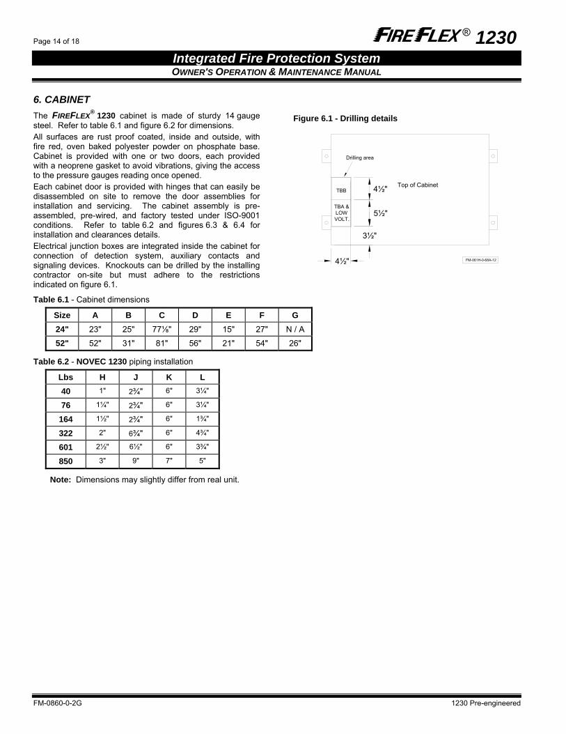
6. CABINET The FIREFLEX® 1230 cabinet is made of sturdy 14 gauge steel. Refer to table 6.1 and figure 6.2 for dimensions. All surfaces are rust proof coated, inside and outside, with fire red, oven baked polyester powder on phosphate base. Cabinet is provided with one or two doors, each provided with a neoprene gasket to avoid vibrations, giving the access to the pressure gauges reading once opened. Each cabinet door is provided with hinges that can easily be disassembled on site to remove the door assemblies for installation and servicing. The cabinet assembly is pre-assembled, pre-wired, and factory tested under ISO-9001 conditions. Refer to table 6.2 and figures 6.3 & 6.4 for installation and clearances details. Electrical junction boxes are integrated inside the cabinet for connection of detection system, auxiliary contacts and signaling devices. Knockouts can be drilled by the installing contractor on-site but must adhere to the restrictions indicated on figure 6.1.
Figure 6.1 - Drilling details
FM-061H-0-68A-12
3½"
4½"
4½"
5½"
TBB
TBA &LOWVOLT.
Top of Cabinet
Drilling area
Table 6.1 - Cabinet dimensions
Size A B C D E F G 24" 23" 25" 77⅛" 29" 15" 27" N / A
52" 52" 31" 81" 56" 21" 54" 26"
Table 6.2 - NOVEC 1230 piping installation
Lbs H J K L 40 1" 2¾" 6" 3¼"
76 1¼" 2¾" 6" 3¼"
164 1½" 2¾" 6" 1¾"
322 2" 6¾" 6" 4¾"
601 2½" 6½" 6" 3¾"
850 3" 9" 7" 5"
Note: Dimensions may slightly differ from real unit.

® 1230 Page 15 of 18 Integrated Fire Protection System OWNER'S OPERATION & MAINTENANCE MANUAL
1230 Pre-engineered FM-0860-0-2G
Figure 6.2 - Cabinet dimensions BA
C
D
A
C
D
L
KJ
H Ø
J
H Ø
FM-061H-1-49B-4
Figure 6.3 - Floor anchoring template
FM-061H-1-49B-6
5''
E
G
Ø3/4"
F
Figure 6.4 - Required clearance
FM-061H-1-49B-7
12''MIN
12''MIN
22''MIN

Page 16 of 18 ® 1230
Integrated Fire Protection System OWNER'S OPERATION & MAINTENANCE MANUAL
FM-0860-0-2G 1230 Pre-engineered
This page is left blank intentionally.

® 1230 Page 17 of 18
Integrated Fire Protection SystemOWNER'S OPERATION & MAINTENANCE MANUAL
1230 Pre-engineered FM-0860-0-2G
7. Limited WarrantyFireFlex Systems Inc. (known herein as "the Manufacturer") warrants to its customer that its products shall be free of defects in material or part(s) and workmanship for a period of twelve (12) months from the date of original delivery, under normal use and service by the Customer (and provided that the product has been properly installed and maintained). The obligation of the Manufacturer in case of a claim made by the Customer hereunder, shall be, at the Manufacturer's option, limited to repair or replace, free of charge for parts or his labor, any product or part, which in the opinion of the Manufacturer, shall be proven to be defective. The Manufacturer will NOT accept labor back-charges incurred by the Customer to repair or replace said product or part. The present warranty shall be void should the product or part(s) be altered by anyone other than the Manufacturer. In case of a claim under the present warranty, the Customer must contact the Manufacturer's Customer Service Department as soon as he is aware of a claim and, subject to the authorization of the manufacturer, return the defective product or part(s), transportation prepaid, to the address listed below. This warranty constitutes the entire warranty given by the Manufacturer to the Customer with respect to the product. The present warranty is non-transferable and non-assignable. The Manufacturer does not represent that the products will prevent any loss by fire or otherwise or that the product will in all cases provide the protection for which it has been installed or intended. The Customer acknowledges that the Manufacturer is not an insurer. The manufacturer shall not be liable for any loss or damages of any nature whatsoever, including but not limited to incidental or special or consequential damages including but not limited to, property damages, personal injury, revenue loss or lost profits, inconveniences, transportation charges or other damages suffered by anyone. There are no other warranties, expressed or implied with regard to the products, other than those contained herein. Some jurisdictions may not allow limitations on how long an expressed warranty lasts, so the above limitations may not apply to you. Under no circumstances, shall the Manufacturer be liable for any loss of, or damage to property, direct or indirect, incidental or special or consequential damages, arising out of the use or inability to use the Manufacturer's products. The Manufacturer shall not be liable for any personal injury which may arise in the course of or as a result of the use of the manufacturer's products. This warranty replaces all previous warranties and is the only warranty given by the Manufacturer with respect to its products. This warranty shall not be modified, unless such modification is made in writing by an executive officer of the Manufacturer. In consideration of the warranty provisions contained herein, the Customer hereby waives the benefit of any statutory warranty or protection or remedy to which he may be entitled under the terms of any sales of goods act or similar legislation available to him in any jurisdiction in which the Customer carries on business.
Defective part(s) must be returned to the address listed below within (30) days of receiving replacement parts(s). If defective part(s) is not returned before delay expires, an invoice will be issued for replacement part(s) and shipping. On reception, an extended analysis will be performed on the said part(s). If proven to be defective, no invoice will be issued. If the part(s) is proven to be in working condition an invoice will be issued for replacement part(s) and shipping. Special Limitation: Due to their self discharge characteristics when not charged during extended storage periods, Batteries supplied with integrated Releasing Control Panels are covered by the above warranty for a period limited to three (3) months only.
Product Support 1-866-347-3353
Our Product Support Organization is dedicated to assisting you regarding our products, warranty and service procedures. The number above is a toll free number to Product Support.
Manufactured by FIREFLEX Systems Inc. 1935, Lionel-Bertrand Blvd.
Boisbriand, Quebec Canada J7N 1N8
Tel.: (450) 437-3473 ◊ Fax: (450) 437-1930 Toll Free: (866) 347-3353
Web site: http://www.fireflex.com ◊ Email: [email protected]