Integrated circuit wafer
20
Integrated circuit Integrated circuit Wafer Wafer
Transcript of Integrated circuit wafer

Integrated circuitIntegrated circuit
WaferWafer

IC WaferIC Wafer
In In electronicselectronics, a , a waferwafer (also called a (also called a sliceslice or or substratesubstrate) ) is a thin slice of is a thin slice of semiconductor materialsemiconductor material, such as a , such as a silicon crystalsilicon crystal, used in the , used in the fabricationfabrication of of integrated circuitsintegrated circuits and other microdevices. and other microdevices.
The wafer serves as the The wafer serves as the substratesubstrate for for microelectronicmicroelectronic devices built in and over the wafer and undergoes devices built in and over the wafer and undergoes many many microfabricationmicrofabrication process steps such as process steps such as dopingdoping or or ion implantationion implantation, , etchingetching, , depositiondeposition of various materials, of various materials, and and photolithographicphotolithographic patterning. Finally the individual patterning. Finally the individual microcircuits are separated (microcircuits are separated (dicingdicing) and ) and packagedpackaged. .

FormationFormation
Wafers are formed of highly pure (99.9999% Wafers are formed of highly pure (99.9999% purity), nearly defect-free single purity), nearly defect-free single crystallinecrystalline material. One material. One process for forming crystalline wafers is known as process for forming crystalline wafers is known as CzochralskiCzochralski growth growth invented by the Polish chemist invented by the Polish chemist Jan Jan CzochralskiCzochralski. In this process, a cylindrical . In this process, a cylindrical ingotingot of high of high purity purity monocrystallinemonocrystalline silicon silicon is formed by pulling a is formed by pulling a seed crystalseed crystal from a ' from a 'meltmelt'. Do pant impurity atoms such '. Do pant impurity atoms such as as boronboron or or phosphorusphosphorus can be added to the molten can be added to the molten intrinsic silicon in precise amounts in order to intrinsic silicon in precise amounts in order to dopedope the the silicon, thus changing it into silicon, thus changing it into n-typen-type or or p-typep-type extrinsic extrinsic silicon. silicon.

Wafer propertiesWafer properties
Silicon wafers are available in a variety of sizes Silicon wafers are available in a variety of sizes from 25.4 mm (1 inch) to 300 mm (11.8 inches).from 25.4 mm (1 inch) to 300 mm (11.8 inches).SemiconductorSemiconductor fabrication plants fabrication plants (also known (also known as as fabsfabs) are defined by the size of wafers that ) are defined by the size of wafers that they are tooled to produce. The size has they are tooled to produce. The size has gradually increased to improve throughput and gradually increased to improve throughput and reduce cost with the current state-of-the-art fab reduce cost with the current state-of-the-art fab considered to be 300 mm (12 inch), with the next considered to be 300 mm (12 inch), with the next standard projected to be 450 mm (18 inch).standard projected to be 450 mm (18 inch).

Wafer propertiesWafer properties
IntelIntel, , TSMCTSMC and and SamsungSamsung are separately are separately conducting research to the advent of 450 conducting research to the advent of 450 mm "mm "prototypeprototype" (research) " (research) fabsfabs by 2012, though by 2012, though serious hurdles remain. serious hurdles remain. Dean FreemanDean Freeman, an , an analyst with analyst with Gartner Inc.Gartner Inc., predicted that , predicted that production fabs could emerge sometime production fabs could emerge sometime between the 2017 and 2019 timeframe, a lot of between the 2017 and 2019 timeframe, a lot of that will depend on a plethora of new that will depend on a plethora of new technological breakthroughs and not simply technological breakthroughs and not simply extending current technology. extending current technology.

Wafer propertiesWafer properties
1-inch (25 mm)1-inch (25 mm) 2-inch (51 mm). Thickness 275 µm.2-inch (51 mm). Thickness 275 µm. 3-inch (76 mm). Thickness 375 µm.3-inch (76 mm). Thickness 375 µm. 4-inch (100 mm). Thickness 525 µm.4-inch (100 mm). Thickness 525 µm. 5-inch (130 mm) or 125 mm (4.9 inch). 5-inch (130 mm) or 125 mm (4.9 inch).
Thickness 625 µm.Thickness 625 µm. 150 mm (5.9 inch, usually referred to as "6 150 mm (5.9 inch, usually referred to as "6
inch"). Thickness 675 µm.inch"). Thickness 675 µm. 200 mm (7.9 inch, usually referred to as "8 200 mm (7.9 inch, usually referred to as "8
inch"). Thickness 725 µm.inch"). Thickness 725 µm.

Wafer propertiesWafer properties
300 mm (11.8 inch, usually referred to as 300 mm (11.8 inch, usually referred to as "12 inch"). Thickness 775 µm."12 inch"). Thickness 775 µm.
450 mm ("18 inch"). Thickness 925 µm 450 mm ("18 inch"). Thickness 925 µm (expected).(expected).

Background of the inventionBackground of the invention 1. Field of the Invention 1. Field of the Invention
The present invention relates to a semiconductor The present invention relates to a semiconductor integrated circuit wafer, a semiconductor integrated integrated circuit wafer, a semiconductor integrated circuit chip, and a method of testing a semiconductor circuit chip, and a method of testing a semiconductor integrated circuit wafer which are suitable for detecting integrated circuit wafer which are suitable for detecting defects of the semiconductor integrated circuit by using a defects of the semiconductor integrated circuit by using a build in self test (BIST) circuit. build in self test (BIST) circuit.
Priority is claimed on Japanese Patent Application No. Priority is claimed on Japanese Patent Application No. 2008-099664, filed Apr. 7, 2008, the content of which is 2008-099664, filed Apr. 7, 2008, the content of which is incorporated herein by reference. incorporated herein by reference.
2. Description of Related Art2. Description of Related Art

Background of the inventionBackground of the invention In a test of a semiconductor integrated circuit wafer, probe pins In a test of a semiconductor integrated circuit wafer, probe pins
(exploring needles) contact with input-output pads (external (exploring needles) contact with input-output pads (external electrodes) in the semiconductor integrated circuit such as a electrodes) in the semiconductor integrated circuit such as a memory, and input test pattern signals which are supplied from a memory, and input test pattern signals which are supplied from a tester via the probe pins, and thus electrical characteristics can be tester via the probe pins, and thus electrical characteristics can be measured to determine whether or not the semiconductor integrated measured to determine whether or not the semiconductor integrated circuit wafer is defective. When the probe pins contact with the circuit wafer is defective. When the probe pins contact with the input-output pads, there may be scars caused by contacting the input-output pads, there may be scars caused by contacting the input-output pad to the probe pins. If the scars occur in the input-input-output pad to the probe pins. If the scars occur in the input-output pads, when wires are bonded to the input-output pads or output pads, when wires are bonded to the input-output pads or bumps are constructed, the scars lead to an increase in defects and bumps are constructed, the scars lead to an increase in defects and to a decrease in reliability of connection. For this reason, it is to a decrease in reliability of connection. For this reason, it is necessary to improve the structure of the input-output pad or the necessary to improve the structure of the input-output pad or the adjustment of contact pressure of the probe pins in order to make it adjustment of contact pressure of the probe pins in order to make it possible to safely test by reducing the scars. possible to safely test by reducing the scars.

Background of the inventionBackground of the invention
On the other hand, there is a method of using a On the other hand, there is a method of using a built in self test (BIST) circuit as a technique of built in self test (BIST) circuit as a technique of efficiently testing the semiconductor integrated efficiently testing the semiconductor integrated circuit. However, when the BIST circuit is built in circuit. However, when the BIST circuit is built in a circuit region of the semiconductor integrated a circuit region of the semiconductor integrated circuit, the chip size of the entire semiconductor circuit, the chip size of the entire semiconductor integrated circuit is increased, and thus the chip integrated circuit is increased, and thus the chip cost rises. In addition, unnecessary BIST circuit cost rises. In addition, unnecessary BIST circuit portions remain after production is complete. portions remain after production is complete. Thereby the consumption power increases. Thereby the consumption power increases.

Background of the inventionBackground of the invention In order to solve the problems of increase in the chip In order to solve the problems of increase in the chip
size or increase in the consumption power, there is size or increase in the consumption power, there is proposed a structure in which the BIST circuit and the proposed a structure in which the BIST circuit and the pads for testing are provided in a scribe region (for pads for testing are provided in a scribe region (for example, refer to Japanese Unexamined Patent example, refer to Japanese Unexamined Patent Application, First Publication, No. 2002-176140). In this Application, First Publication, No. 2002-176140). In this related art, there is a need for the probe pins coming into related art, there is a need for the probe pins coming into contact with both the pads for testing the BIST circuit in contact with both the pads for testing the BIST circuit in the scribe region and the input-output pads of a the scribe region and the input-output pads of a semiconductor integrated circuit region in order to be semiconductor integrated circuit region in order to be electrically connected with each other via the probe pins electrically connected with each other via the probe pins as a transmission path. For this reason, there are as a transmission path. For this reason, there are problems in that (i) the number of the probe pins is problems in that (i) the number of the probe pins is increased, so that a testing tool (probe card) is increased, so that a testing tool (probe card) is complicated and the cost is increased; and (ii) the complicated and the cost is increased; and (ii) the electrical characteristics of the testing tool affects the electrical characteristics of the testing tool affects the test of the semiconductor integrated circuit. test of the semiconductor integrated circuit.
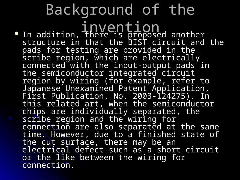
Background of the inventionBackground of the invention In addition, there is proposed another structure In addition, there is proposed another structure
in that the BIST circuit and the pads for testing in that the BIST circuit and the pads for testing are provided in the scribe region, which are are provided in the scribe region, which are electrically connected with the input-output pads electrically connected with the input-output pads in the semiconductor integrated circuit region by in the semiconductor integrated circuit region by wiring (for example, refer to Japanese wiring (for example, refer to Japanese Unexamined Patent Application, First Unexamined Patent Application, First Publication, No. 2003-124275). In this related Publication, No. 2003-124275). In this related art, when the semiconductor chips are art, when the semiconductor chips are individually separated, the scribe region and the individually separated, the scribe region and the wiring for connection are also separated at the wiring for connection are also separated at the same time. However, due to a finished state of same time. However, due to a finished state of the cut surface, there may be an electrical defect the cut surface, there may be an electrical defect such as a short circuit or the like between the such as a short circuit or the like between the wiring for connection.wiring for connection.

Background of the inventionBackground of the invention In addition, there is disclosed a technique of In addition, there is disclosed a technique of
forming wiring for connecting a testing circuit forming wiring for connecting a testing circuit and a functional circuit, and switch elements for and a functional circuit, and switch elements for electrically separating the wiring (for example, electrically separating the wiring (for example, refer to Japanese Unexamined Patent refer to Japanese Unexamined Patent Application, First Publication, No. 2001-085479). Application, First Publication, No. 2001-085479). In this related art, there is no description about In this related art, there is no description about the pads of the testing circuit (BIST circuit) and the pads of the testing circuit (BIST circuit) and the functional circuit (semiconductor integrated the functional circuit (semiconductor integrated circuit) and effects thereof, and there is no circuit) and effects thereof, and there is no suggestion of a method which improves the suggestion of a method which improves the scars of the input-output pads that should be scars of the input-output pads that should be solved.solved.

Key BenefitsKey Benefits
Etch Rate for silicon wafers (150.... 200mm) > 25 µm/min, thus high Etch Rate for silicon wafers (150.... 200mm) > 25 µm/min, thus high throughputthroughput
Homogeneity of etch rate (wafer thickness) ± 2% typically, ± 5% Homogeneity of etch rate (wafer thickness) ± 2% typically, ± 5% guaranteedguaranteed
Surface quality is adjustable from as polished to velvet-likeSurface quality is adjustable from as polished to velvet-like Wafer bow and war page improvement after dry etchingWafer bow and war page improvement after dry etching Die breaking strength improvement after damage removal and Die breaking strength improvement after damage removal and
stress reliefstress relief Wafer edges: soft edge rounding avoids wafer breakage caused by Wafer edges: soft edge rounding avoids wafer breakage caused by
sharp wafer edgessharp wafer edges Wafer temperature Wafer temperature typically < 100 °C, guaranteed < 120 °Ctypically < 100 °C, guaranteed < 120 °C Wafer handling: wafer fixed in defined positionWafer handling: wafer fixed in defined position Low energy and gas consumptionLow energy and gas consumption Lower cost of ownership (< USD 2.00/wafer)Lower cost of ownership (< USD 2.00/wafer)

Integrated Circuit WaferIntegrated Circuit Wafer

SummarySummary The present invention seeks to solve one or more of the above The present invention seeks to solve one or more of the above
problems, or to improve those problems at least in part. problems, or to improve those problems at least in part.
In one embodiment, there is provided a semiconductor integrated In one embodiment, there is provided a semiconductor integrated circuit wafer that includes: a plurality of semiconductor integrated circuit wafer that includes: a plurality of semiconductor integrated circuit regions each of which includes a semiconductor integrated circuit regions each of which includes a semiconductor integrated circuit formed thereon; a scribe region which separates the circuit formed thereon; a scribe region which separates the semiconductor integrated circuit regions adjacent to each other; a semiconductor integrated circuit regions adjacent to each other; a build in self test (BIST) circuit which is provided in the scribe region build in self test (BIST) circuit which is provided in the scribe region and inspects the semiconductor integrated circuit; a connection and inspects the semiconductor integrated circuit; a connection wiring which is formed ranging from the scribe region to the wiring which is formed ranging from the scribe region to the semiconductor integrated circuit region and connects the semiconductor integrated circuit region and connects the semiconductor integrated circuit and the BIST circuit; a BIST semiconductor integrated circuit and the BIST circuit; a BIST switching signal input pad which is provided in the semiconductor switching signal input pad which is provided in the semiconductor integrated circuit region; and a BIST switching circuit which is integrated circuit region; and a BIST switching circuit which is provided in the semiconductor integrated circuit region and is driven provided in the semiconductor integrated circuit region and is driven by a driving signal input from the BIST switching signal input pad, by a driving signal input from the BIST switching signal input pad, the BIST switching circuit including: an input-output pad which the BIST switching circuit including: an input-output pad which connects with the semiconductor integrated circuit through a circuit connects with the semiconductor integrated circuit through a circuit wiring; and a switch element which is provided at a middle position wiring; and a switch element which is provided at a middle position of the circuit wiring and is driven by the driving signal input from the of the circuit wiring and is driven by the driving signal input from the BIST switching signal input pad.BIST switching signal input pad.

SummarySummary In another embodiment, there is provided a In another embodiment, there is provided a
semiconductor integrated circuit chip which is semiconductor integrated circuit chip which is obtained by dividing a semiconductor integrated obtained by dividing a semiconductor integrated circuit wafer along a scribe region. The circuit wafer along a scribe region. The semiconductor integrated circuit chip includes: a semiconductor integrated circuit chip includes: a semiconductor integrated circuit; a build in self semiconductor integrated circuit; a build in self test (BIST) switching signal input pad; and a test (BIST) switching signal input pad; and a BIST switching circuit which is driven by a BIST switching circuit which is driven by a driving signal input from the BIST switching driving signal input from the BIST switching signal input pad, the BIST switching circuit signal input pad, the BIST switching circuit including: an input-output pad which connects including: an input-output pad which connects with the semiconductor integrated circuit through with the semiconductor integrated circuit through a circuit wiring; and a switch element which is a circuit wiring; and a switch element which is provided at a middle position of the circuit wiring provided at a middle position of the circuit wiring and is driven by the driving signal input from the and is driven by the driving signal input from the BIST switching signal input pad.BIST switching signal input pad.

SummarySummary In another embodiment, there is provided a In another embodiment, there is provided a
method of testing a semiconductor integrated method of testing a semiconductor integrated circuit included in a semiconductor integrated circuit included in a semiconductor integrated circuit wafer, the semiconductor integrated circuit wafer, the semiconductor integrated circuit wafer including: a plurality of circuit wafer including: a plurality of semiconductor integrated circuit regions each semiconductor integrated circuit regions each formed with the semiconductor integrated circuit; formed with the semiconductor integrated circuit; a scribe region which separates the a scribe region which separates the semiconductor integrated circuit regions semiconductor integrated circuit regions adjacent to each other; a build in self test (BIST) adjacent to each other; a build in self test (BIST) circuit which is provided in the scribe region; a circuit which is provided in the scribe region; a connection wiring which connects the connection wiring which connects the semiconductor integrated circuit and the BIST semiconductor integrated circuit and the BIST circuit; a BIST switching signal input pad which circuit; a BIST switching signal input pad which is provided in the semiconductor integrated is provided in the semiconductor integrated circuit region, circuit region,

SummarySummary the BIST switching circuit including an input-output pad the BIST switching circuit including an input-output pad
which connects with the semiconductor integrated circuit which connects with the semiconductor integrated circuit through a circuit wiring, and a switch element which is through a circuit wiring, and a switch element which is provided at a middle position of the circuit wiring, the provided at a middle position of the circuit wiring, the method comprising: connecting a probe pin of a probe method comprising: connecting a probe pin of a probe card with the BIST circuit and the BIST switching signal card with the BIST circuit and the BIST switching signal input pad; inputting a driving signal to the BIST switching input pad; inputting a driving signal to the BIST switching signal input pad to turn on the switch element in the signal input pad to turn on the switch element in the BIST switching circuit so as to disconnect the circuit BIST switching circuit so as to disconnect the circuit wiring and connect the BIST circuit with the wiring and connect the BIST circuit with the semiconductor integrated circuit via the connection semiconductor integrated circuit via the connection wiring; inputting an information signal to the BIST circuit wiring; inputting an information signal to the BIST circuit via the probe pin from a tester; and inputting the input via the probe pin from a tester; and inputting the input information signal to the semiconductor integrated circuit information signal to the semiconductor integrated circuit via the connection wiring to inspect the semiconductor via the connection wiring to inspect the semiconductor integrated circuit.integrated circuit.

Submitted by : Michael Dave M. BactongSubmitted by : Michael Dave M. Bactong
Paul Adrian MagdalePaul Adrian Magdale