Insulation Co-ordination For HVDC Station · PDF fileInsulation Co-ordination For HVDC...
52
Insulation Co-ordination For HVDC Station
Transcript of Insulation Co-ordination For HVDC Station · PDF fileInsulation Co-ordination For HVDC...

Insulation Co-ordinationFor HVDC Station
Insulation Co-ordination
Definitions
As per IEC 60071“ Insulation Coordination is defined as selection of dielectric
strength of equipment in relation to the operating voltages and overvoltages which can appear on the system for which the equipment is intended and taking into account the service environment and the characteristics of the available preventing and protective devices”
As per IEEE 1313.1“The selection of insulation strength consistent with expected
over voltages to obtain an acceptable risk of failure.”

TS requirement….
‘’ The contractor shall provide surge arresters, surge capacitors, and other devices as required to protect all the equipment within the station from dc, fundamental frequency, harmonic, ferro-resonant, switching surge and lightning impulse overvoltages under all steady state, dynamic and transient conditions.’’

TS requirement….
The insulation of the equipment and protective levels of arresters connected to the 400 kV and 230kV AC bus bars of the Back-to-Back HVDC stations shall be coordinated with the insulation and surge arrester characteristics of the Employer's 400 kV and 230 kV AC systems to which the back-to-back HVDC station is connected.
The Contractor shall take into account the possible ac line discharge energy which could be present in the back-to-back HVDC Station arresters. In addition the Contractor shall ensure that the discharge duty of the Employer's arresters is not increased due to infeed from the back-to-back hvdc station.
The Contractor shall coordinate the ac filter bank surge arrester characteristics so that these arresters will discharge the energy in the ac filter and shunt capacitors (if used) and will prevent the capacitors from being charged to a level which can not be discharged by other arresters connected to the 400 kV and 230kV ac system.

� The examination and predication of prospective overvoltages and
continuous voltage stresses occurring on transmission equipment
with respect to determining-
� Overvoltage Insulation Withstand (ie BIL, BSL)
� Clearance in Air
� Creepage across shed surfaces of insulators and bushings
� Rating and positioning of protective devices to limit
� Overvoltage
� Equipment Test Requirements
Insulation Co-ordination….
General Principles
� Sources or Overvoltage:
� Switching Impulse
� Lightning Impulse
� FOW (Fast Front of Wave)
� Power Frequency
General Principles
� Switching Impulse
� Typically defined as:
� Voltage wavefront 250/2500 micro sec (IEC)
� Current wavefront 36/90 micro sec
� Caused by:
� Circuit breaker operation
� Protective Switching
� Equipment Energisation
� Load Rejections
� Convertor switching transients
General Principles
� Lightning Impulse
� Definition
� Voltage wavefront: 1.2/50 micro sec (IEC60071)
� Current wavefront: 8/20 micro sec (IEC600990-1)
� Origins
� Direct lightning stroke to line - rare on shielded systems
� Back flashover - lightning strikes pylon sheild wires
General Principles
� FOW (Front of Wave) Impulse
� Definition
� Current wave front: 1/2 micro sec
� Origin
� Bushing flashovers within valve hall, causing discharge of
stray capacitances through relatively short lengths of
conductor
General Principles
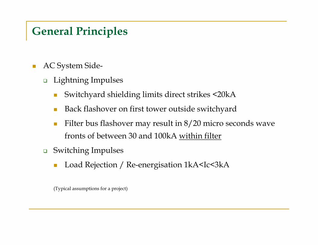
� AC System Side-
� Lightning Impulses
� Switchyard shielding limits direct strikes <20kA
� Back flashover on first tower outside switchyard
� Filter bus flashover may result in 8/20 micro seconds wave
fronts of between 30 and 100kA within filter
� Switching Impulses
� Load Rejection / Re-energisation 1kA<Ic<3kA
(Typical assumptions for a project)
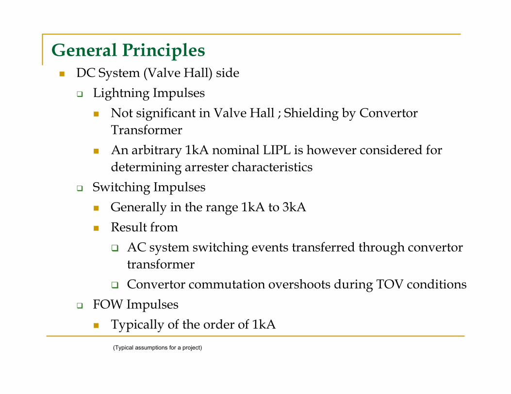
General Principles� DC System (Valve Hall) side
� Lightning Impulses
� Not significant in Valve Hall ; Shielding by Convertor
Transformer
� An arbitrary 1kA nominal LIPL is however considered for
determining arrester characteristics
� Switching Impulses
� Generally in the range 1kA to 3kA
� Result from
� AC system switching events transferred through convertor
transformer
� Convertor commutation overshoots during TOV conditions
� FOW Impulses
� Typically of the order of 1kA
(Typical assumptions for a project)
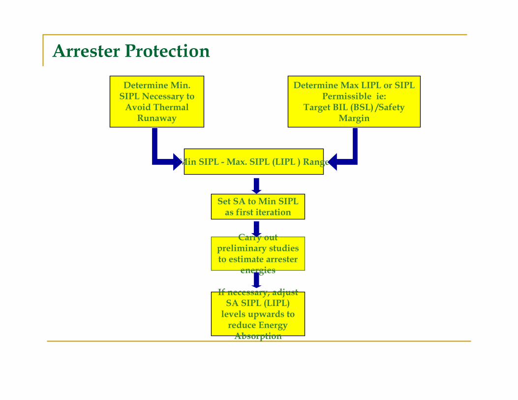
Determine Min. SIPL Necessary to Avoid Thermal
Runaway
Determine Max LIPL or SIPL Permissible ie:
Target BIL (BSL) /Safety Margin
Min SIPL - Max. SIPL (LIPL ) Range
Set SA to Min SIPL as first iteration
Carry out preliminary studies to estimate arrester
energies
If necessary, adjust SA SIPL (LIPL) levels upwards to reduce Energy Absorption
Arrester Protection
� The starting point of the insulation co-ordination process within the
valve hall is the rating of the valve surge arrester (V) by balancing
continuous energy absorption against protective level.
� Once the valve arrester switching impulse protective level (SIPL)
has been determined, all other switching impulse protective levels
throughout the system may be established.
� Lightning impulse protective levels (LIPL) may then be established
by applying a typical manufacturer ratio of LIPL to SIPL.
Surge Arrester Protection
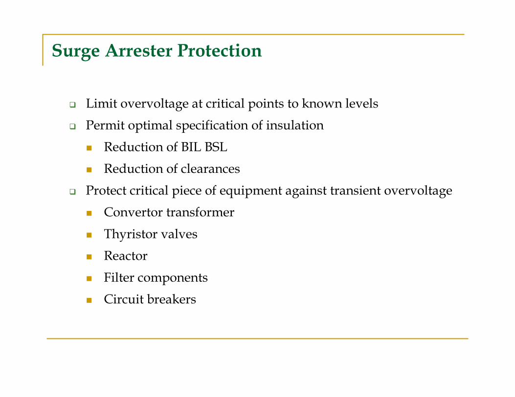
Surge Arrester Protection
� Limit overvoltage at critical points to known levels
� Permit optimal specification of insulation
� Reduction of BIL BSL
� Reduction of clearances
� Protect critical piece of equipment against transient overvoltage
� Convertor transformer
� Thyristor valves
� Reactor
� Filter components
� Circuit breakers
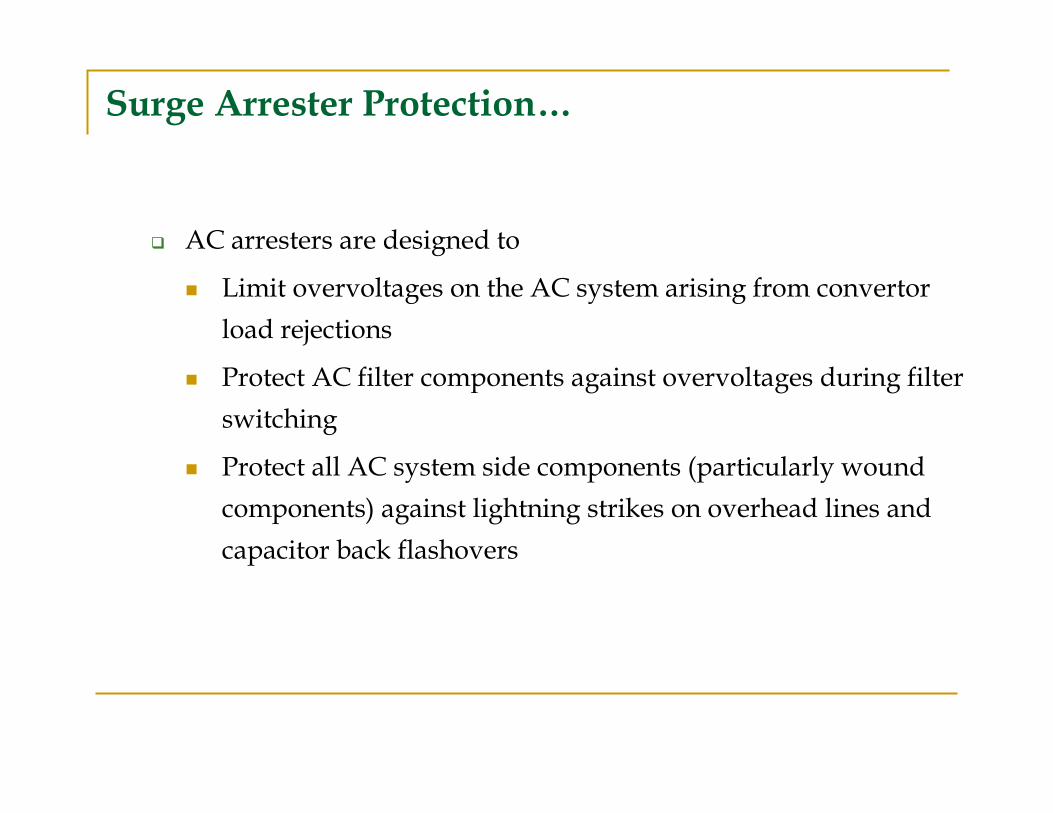
Surge Arrester Protection…
� AC arresters are designed to
� Limit overvoltages on the AC system arising from convertor
load rejections
� Protect AC filter components against overvoltages during filter
switching
� Protect all AC system side components (particularly wound
components) against lightning strikes on overhead lines and
capacitor back flashovers
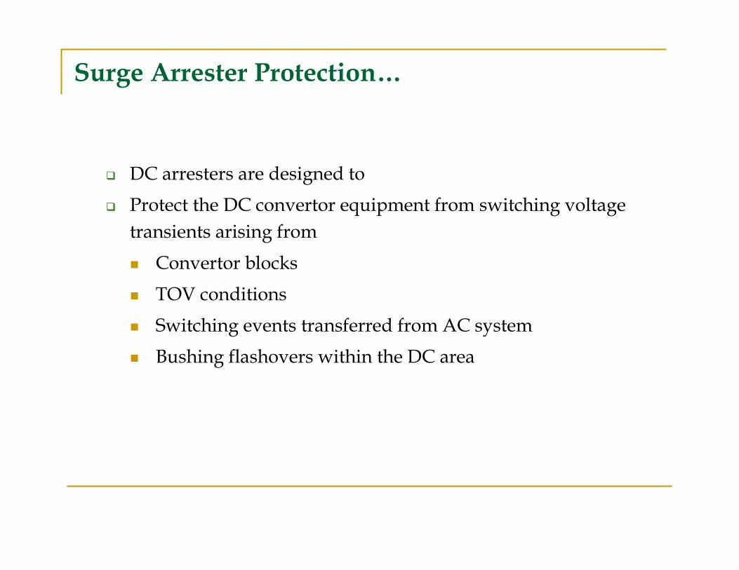
Surge Arrester Protection…
� DC arresters are designed to
� Protect the DC convertor equipment from switching voltage
transients arising from
� Convertor blocks
� TOV conditions
� Switching events transferred from AC system
� Bushing flashovers within the DC area
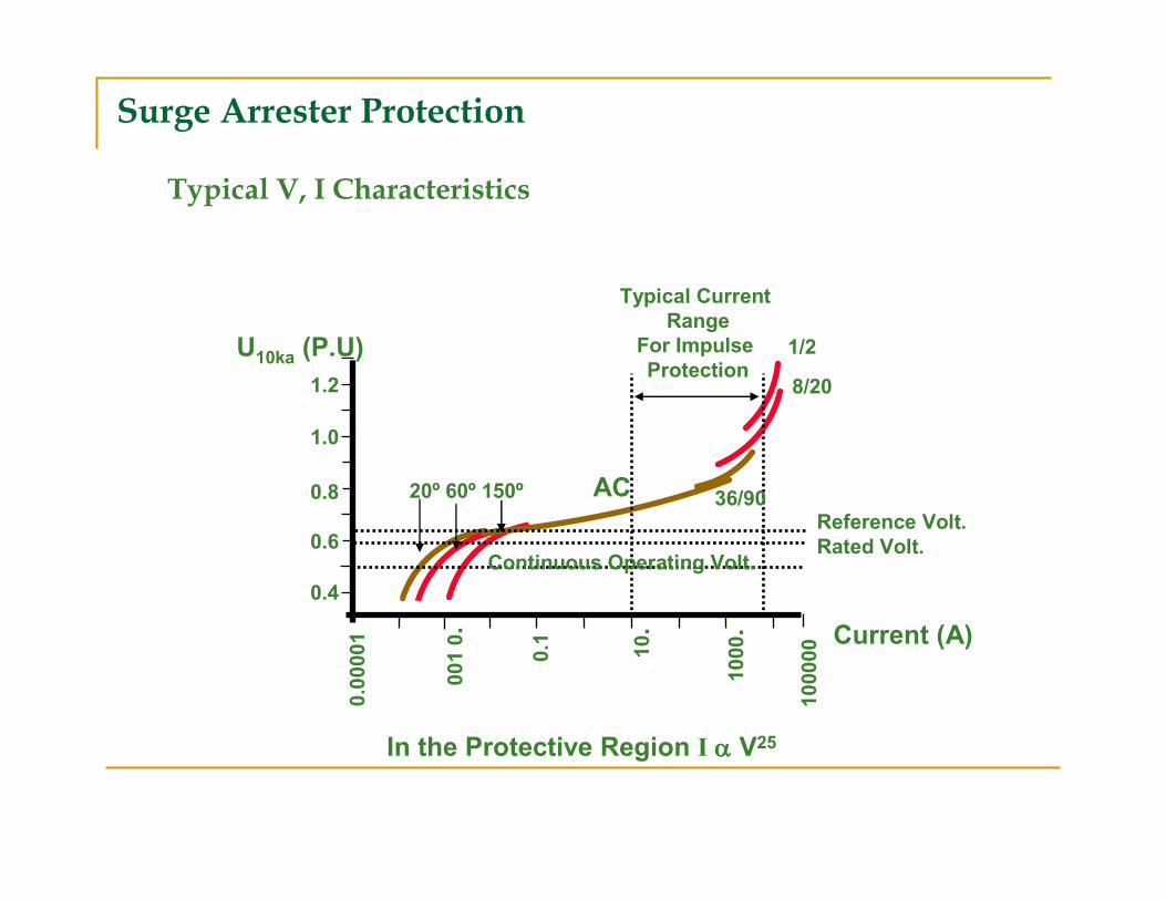
0.00001
001 0.
0.1 10.
1000.
100000
0.4
0.6
0.8
1.0
1.2
U10ka (P.U)
Typical Current
Range
For Impulse
Protection1/2
8/20
36/90Reference Volt.
Rated Volt.Continuous Operating Volt.
20º 60º 150º
Current (A)
In the Protective Region I αααα V25
AC
Typical V, I Characteristics
Surge Arrester Protection
Overvoltages Limitations carried out In two ways…
� By suitable system design
� By suitable co-ordination between insulation and surge – arrester protection
System Design
On DC side Over Voltages can be reduced by-
� Shielding the converter station and Transmission lines
� Suitable design of the converter control equipment.
� Selecting system parameters to try and avoid resonance under fault
conditions.
On the AC side….
� Voltage support equipment is essential to provide voltage control during transient and dynamic system disturbances.
� Compensating equipments requires detailed studies to determine the relationship between DC system recovery and voltage support equipment and response time
System Design
Fundamental Differences Between AC and HVDC Insulation Co-ordination Philosophy
� AC System consists of parallel connected circuits and apart from some special cases the requirement is to establish the insulation level bet. phase to earth and phase to phase level.
� HVDC converter stations on the other hand consist of series connected bridges, each bridge requiring a different insulation strength to earth and within each bridge the electric strength is different for the various components.
Basic Differences Between AC And DC Arrester
� Arresters on AC side are
usually specified by their rated
voltage and maximum
continuous operating voltage
� On DC side rated voltage is
not defined and continuous
operating voltage is defined
differently.
Rated Voltage for Arresters For DC Application are Specified As:
� PCOV (Peak Continuous Operating Voltage)
� CCOV (Crest Continuous Operating Voltage)
� ECOV (Equivalent Continuous Operating Voltage)
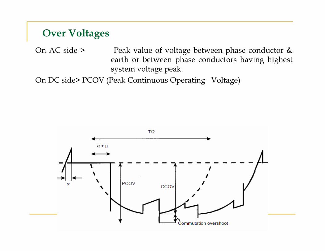
Over Voltages
On AC side > Peak value of voltage between phase conductor & earth or between phase conductors having highest system voltage peak.
On DC side> PCOV (Peak Continuous Operating Voltage)
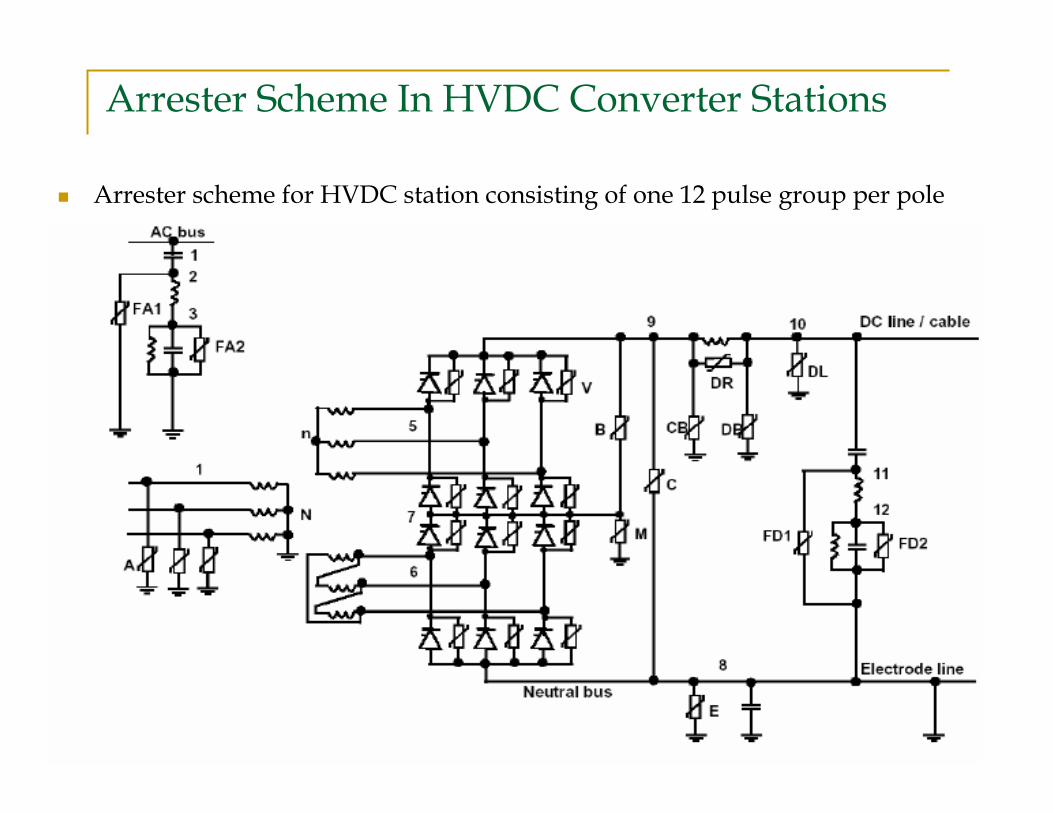
Arrester Scheme In HVDC Converter Stations
� Arrester scheme for HVDC station consisting of one 12 pulse group per pole
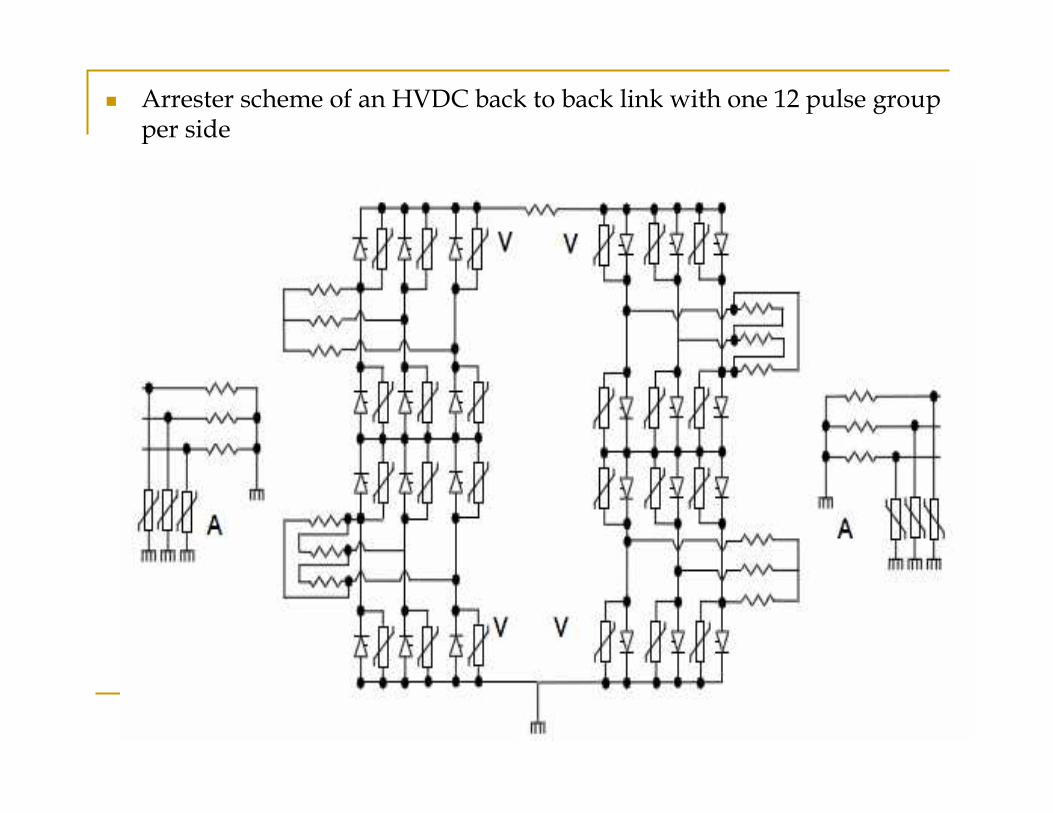
� Arrester scheme of an HVDC back to back link with one 12 pulse group per side
AC Bus Arrester (A)
� These are usually located close to the termination of AC-Lines and
close to the transformers in order to get adequate protection for
lightning surges, switching surge overvoltages and to some extent
also for fast transient at breaker operations.
� Need to be co-ordinated with existing arresters in the AC network.
� The protection levels are often selected lower than for the existing
AC arresters. This avoids overstressing of the existing arresters
Valve Arrester (V)
� Protect the thyristor valves from excessive over voltages.
� Protective level of V arrester should be selected as low as possible.
� The required insulation level to ground of the transformer valve
winding and for various points within the converter bridge
depends on protective level of V arrester in series with other
arresters.
� As an example the phase-to-ground insulation of delta connected
transformer is determined by arrester V in series with arrester E
Mid Point DC Bus Arrester (M)
� This arrester protects the windings of the upper transformer if external
overvoltages (e.g. lightning strokes) to ground are possible between the
transformer and the valves
� This arrester prevent the protection level of the lower bridge from climbing at
no load to the value of two series connected V arresters

Bridge Arrester (B)
� The bridge arrester provides protection across the bridge and sometimes in
conjunction with the mid point arrester, provides protection from dc bus
to ground
� This arrester is normally not used in low voltage back-to-back schemes.
Converter Unit DC Bus Arrester (CB)
� Main task is to protect the valve side terminal of the smoothing reactor
against lightning surge in case of shielding failure.
� This arrester protect the top of converter valve structure and also protect
the top converter transformer winding against surges entering from dc
side.
Converter unit Arrester (C)
� Normally connected between the high voltage and the neutral bus and
provide protection of the 12 pulse bridge.
� This arrester may limit overvoltages due to lightning stresses propagating
into the valve area.
DC Bus Arrester (DB)/DC Line Arrester (DL)
� The purpose of the dc bus arrester is to protect dc side equipment of
HVDC station against overvoltages.
� Because of distance effects more than one arrester is used, the one on the
line entrance is called DC Line Arrester (DL)
Station Neutral Bus Arrester (E)
These arresters are provided to protect equipment from fast-front
overvoltages entering the neutral bus and to discharge large energies
during following contingencies:
1. Earth fault on the dc bus.
2. Earth fault between the valves and converter transformer.
3. Loss of return path during monopolar operation.
DC Filter Circuit Arrester (FD)
� These arresters protects filter circuit elements such as reactors and
damping resistors against overvoltages when a filter circuit is energized
from the dc bus bar or in the event of busbar short circuit to ground.
� In the later case energy stored in the main capacitor discharges into FD
arrester.
Smoothing Reactor Arrester (DR)
Employed to limit the voltage across the winding in the event that
voltages of opposite polarity occur on both side of the smoothing
reactor.
However, because this impairs the protection against in-coming
travelling waves from the HVDC overhead line, most system do not
employ DR arrester.
Insulation Withstand:
� Insulation withstand is the capability of a given item of equipment
to withstand applied transient overvoltages (switching, lightning
and fast front) and power frequency overvoltages. In terms of
transient overvoltage withstand the key parameters are:
� BIL: Basic Insulation Level: The proven ability of an item of
equipment to withstand the lightning impulse voltage transient
(typically defined as 1.2/50µs wavefront).
� BSL: Basic Switching Level: The proven ability of an item of
equipment to withstand the switching impulse voltage transient
(typically defined as a 250/2500µs wavefront).
To Find The Withstand Level And Corresponding Clearance
1. The arrester protective Levels are established by considering system
operating parameters and system studies.
2. Insulation withstand levels are established by application of margins
detailed in the specification.
3. Once the insulation withstand requirements are established clearance
is determined by calculation.
4. Creepages are established from steady state operating voltages and
specific creepage distances detailed by Employer’s Requirement.
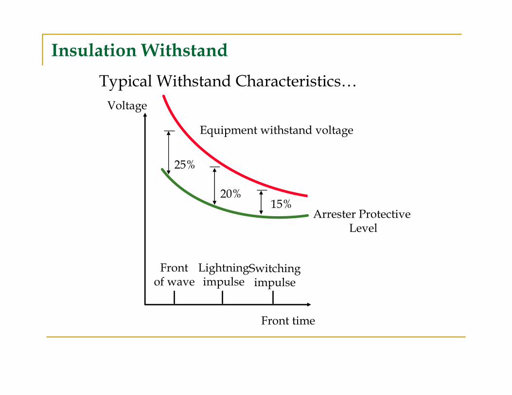
15%20%
25%
Frontof wave
Lightningimpulse
Switchingimpulse
Front time
Voltage
Equipment withstand voltage
Typical Withstand Characteristics…
Arrester Protective Level
Insulation Withstand
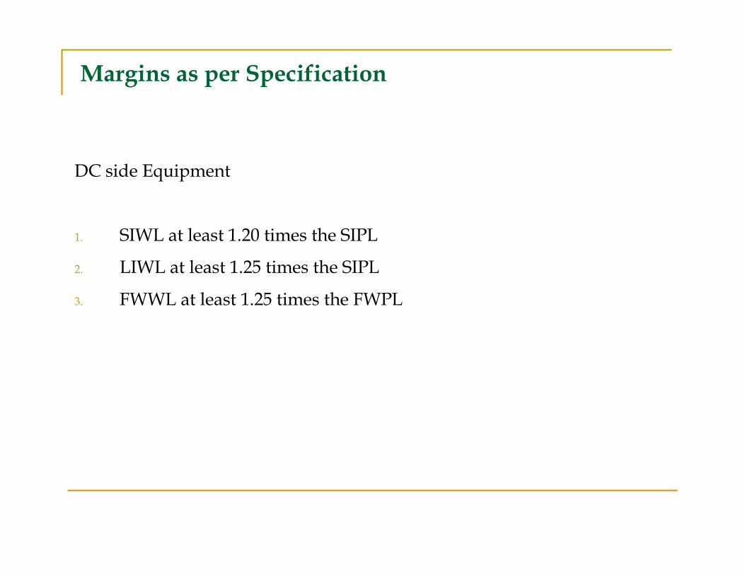
Margins as per Specification
DC side Equipment
1. SIWL at least 1.20 times the SIPL
2. LIWL at least 1.25 times the SIPL
3. FWWL at least 1.25 times the FWPL
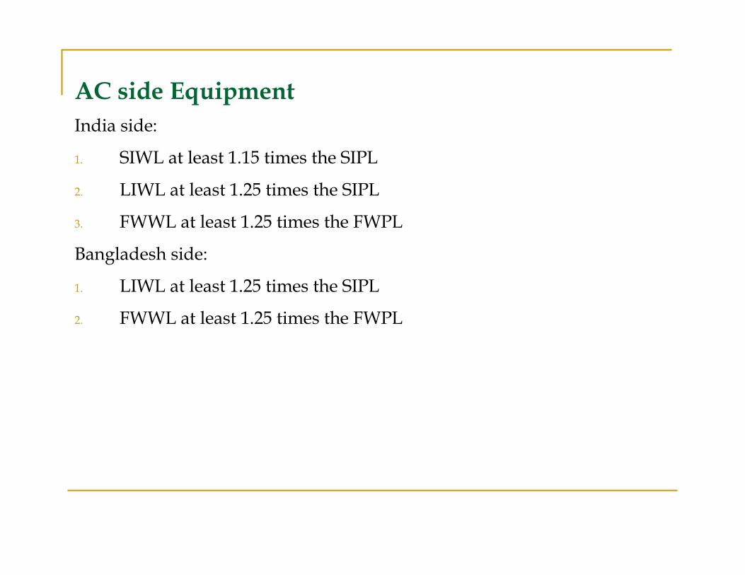
AC side Equipment
India side:
1. SIWL at least 1.15 times the SIPL
2. LIWL at least 1.25 times the SIPL
3. FWWL at least 1.25 times the FWPL
Bangladesh side:
1. LIWL at least 1.25 times the SIPL
2. FWWL at least 1.25 times the FWPL
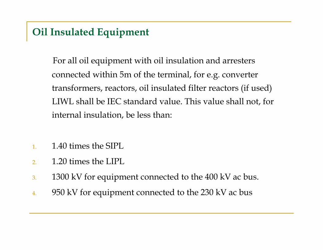
Oil Insulated Equipment
For all oil equipment with oil insulation and arresters
connected within 5m of the terminal, for e.g. converter
transformers, reactors, oil insulated filter reactors (if used)
LIWL shall be IEC standard value. This value shall not, for
internal insulation, be less than:
1. 1.40 times the SIPL
2. 1.20 times the LIPL
3. 1300 kV for equipment connected to the 400 kV ac bus.
4. 950 kV for equipment connected to the 230 kV ac bus

5. Air Clearances
A. AC switchyard
B. DC side
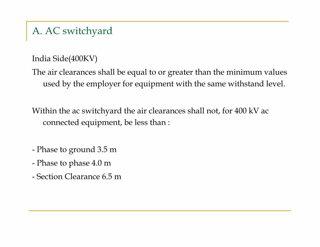
A. AC switchyard
India Side(400KV)
The air clearances shall be equal to or greater than the minimum values
used by the employer for equipment with the same withstand level.
Within the ac switchyard the air clearances shall not, for 400 kV ac
connected equipment, be less than :
- Phase to ground 3.5 m
- Phase to phase 4.0 m
- Section Clearance 6.5 m
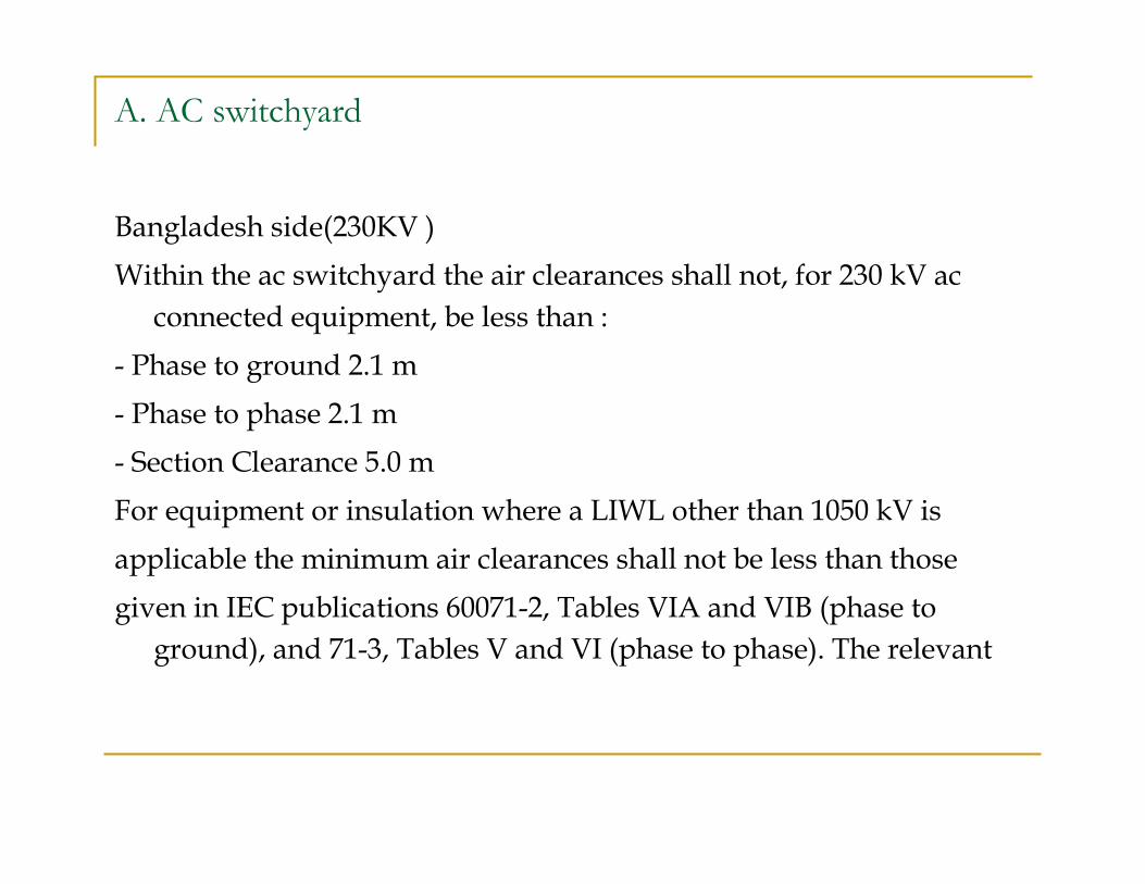
A. AC switchyard
Bangladesh side(230KV )
Within the ac switchyard the air clearances shall not, for 230 kV ac
connected equipment, be less than :
- Phase to ground 2.1 m
- Phase to phase 2.1 m
- Section Clearance 5.0 m
For equipment or insulation where a LIWL other than 1050 kV is
applicable the minimum air clearances shall not be less than those
given in IEC publications 60071-2, Tables VIA and VIB (phase to
ground), and 71-3, Tables V and VI (phase to phase). The relevant
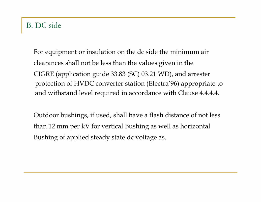
B. DC side
For equipment or insulation on the dc side the minimum air
clearances shall not be less than the values given in the
CIGRE (application guide 33.83 (SC) 03.21 WD), and arrester
protection of HVDC converter station (Electra’96) appropriate to
and withstand level required in accordance with Clause 4.4.4.4.
Outdoor bushings, if used, shall have a flash distance of not less
than 12 mm per kV for vertical Bushing as well as horizontal
Bushing of applied steady state dc voltage as.
6. Leakage Distances
A. AC switchyard
B. DC equipment
A. AC switchyard
The leakage distance for all ac insulators shall not be less than 43
mm per kV of the maximum normal operating phase to ground
voltage at the insulator. The maximum normal operating voltage is defined as the crest value of the voltage, including voltage
distortion effects divided by the square root of 2.
The maximum normal operating fundamental frequency 400 kV ac bus voltage shall be taken as 420 kV rms phase to Phase.
The maximum normal operating fundamental frequency 230 kV ac bus voltage shall be taken as 245 kV rms phase to Phase
B. DC equipment
All dc bushings shall be placed indoors.
Based on the crest voltage the minimum leakage distance (excluding tolerance) shall not be less than :
.1 2.0 cm/kV for indoor porcelain/ silicone rubber insulation inclean surroundings
.2 5.0 cm/kV for outdoor silicone rubber insulators mounted vertically*
B. DC equipment
5.0 cm/kV for outdoor silicone rubber insulators mounted horizontally*
5.0 cm/kV for outdoor silicone rubber bushings mounted vertically*
5.0 cm/kV for outdoor silicone rubber bushings mounted other than vertically*.
B. DC equipment
6.0 cm/KV for outdoor porcelain insulators/ bushings.
*Outdoor bushings shall be only of silicone rubber type. The requirement of 20 mm/KV within the valve hall applies to all silicone rubber/ porcelain insulators and bushings external to the valve. The definition of valve being as given in IEC 60700-1.

THANKYOU