Insulated Metal Panels - Insulated Panels | IMPs | All ... · 6 Insulated metal panels also offer...
32
Selection Guideline For Insulated Metal Panels
Transcript of Insulated Metal Panels - Insulated Panels | IMPs | All ... · 6 Insulated metal panels also offer...

Selection Guideline
For
Insulated Metal Panels

2
Copyright © 2010 Metal Construction Association. All rights reserved. No part of this publication may be reproduced in any form or by any means, including photocopying, or utilized by any information storage or retrieval system without permission of the copyright owner.

3
TABLE OF CONTENTS
SECTION 1: ASSOCIATION BACKGROUND .............................................................................. 4 SECTION 2: INTRODUCTION ......................................................................................................... 5 What Are Insulated Metal Panels and How Are They Manufactured? ............................. 5 How Do IMPs Compare to Other Systems? .......................................................................... 5 Why Choose Insulated Metal Wall and Roof Systems? ....................................................... 8 Performance Criteria .............................................................................................................. 9 Panel Thickness Variation ................................................................................................... 10 R Value Comparison ............................................................................................................. 11 Where Are Insulated Metal Panels Used? ........................................................................... 11 Panel Selection ....................................................................................................................... 12 Finish Selection ...................................................................................................................... 12 SECTION 3: PRODUCT TESTING AND CERTIFICATION ..................................................... 14 Fire .......................................................................................................................................... 14 Structural ............................................................................................................................... 14 Listings ................................................................................................................................... 14 Thermal Transmittance ........................................................................................................ 15 Core Physical Properties ....................................................................................................... 15 Water Penetration ................................................................................................................. 15 Air Infiltration ....................................................................................................................... 15 SECTION 4: PRODUCTION PROCESS ........................................................................................ 16 Product Description .............................................................................................................. 17 SECTION 5: DESIGN PARAMETERS .......................................................................................... 19 Thermal Effects ..................................................................................................................... 19 Metal Roof End Laps ............................................................................................................ 20 Metal Roof Slope ................................................................................................................... 20 Metal Roof Penetrations ....................................................................................................... 20 SECTION 6: INSTALLATION ........................................................................................................ 21 Support Gauge and Alignment ............................................................................................ 21 Panel Layout .......................................................................................................................... 22 Panel Trim ............................................................................................................................. 22 Panel Clips and Fasteners ..................................................................................................... 23 Panel Caulking and Sealants ................................................................................................ 23 Summary ................................................................................................................................ 23 SECTION 7: DETAIL ILLUSTRATIONS ...................................................................................... 24 Vertical Panel Details ....................................................................................................... 24-27 Horizontal Panel Details ....................................................................................................... 28 Roof Panel Details ............................................................................................................ 29-30 ADDENDUM 1: Features and Benefits ............................................................................................ 31 ADDENDUM 2: Insulated Metal Panel Guide Specifications Bullets ........................................... 32

4
INSULATED METAL PANEL (IMP)
WALL AND ROOF SYSTEMS
SECTION 1: ASSOCIATION BACKGROUND The Metal Construction Association (MCA) was formed in 1983 as a non-profit organization. The primary purpose of the Association is to promote the wider use of metal in construction. MCA unites diverse industry segments for this common purpose. One of these segments is Insulated Metal Panels. Disclaimer: This Guideline is for general information only. It is designed to highlight areas requiring consideration. Information contained in the Guideline should not be used without first securing competent advice concerning application suitability for any given building project. MCA does not assume responsibility and disclaims any representation or warranty, express or implied, that such information is suitable for any general or particular use. Anyone making use of this Guideline assumes all liability resulting from such use. The existence of this Guideline does not in any respect preclude a member or non-member of MCA from manufacturing, selling or specifying products not conforming to the Guideline, nor does the existence of an MCA Guideline preclude its voluntary use by persons other than MCA members. This Guideline does not purport to address all safety problems associated with its use or all applicable regulatory requirements. It is the responsibility of the user of this Guideline to establish appropriate safety and health practices and to determine the applicability of regulatory limitations before use of the Guideline.
The Metal Construction Association reserves the right to change, revise, add to, or delete any data contained in this manual without prior notice.
5
SECTION 2: INTRODUCTION
What Are Insulated Metal Panels and How Are They Manufactured? Since the 1960s, contractors and designers of commercial, industrial and refrigerated buildings have relied on insulated metal panels for their excellent thermal efficiency, ease of installation and overall structural integrity. Insulated metal panels in their simplest form are rigid foam sandwiched between two sheets of coated metal. They are molded in a variety of styles and sizes depending on application. Steel or aluminum panel facings create a vapor barrier and provide long-term thermal stability. The skins are resistant to abuse and come in a multitude of colors. Panels are often factory manufactured using the foamed-in place process. Foam is injected, as a liquid or froth, between the sheets of metal. It undergoes a chemical reaction causing it to rise and bond to the metal skins, filling the interior cavity, creating a solid monolithic panel that maintains a consistent thermal value and resists moisture, insect and rodent infiltration. Insulated metal panels can also be manufactured by a laminating process. In this method, pre-cured foam board stock is adhered to preformed metal facers with structural adhesives and placed under pressure in a platen press operation. With both types of Insulated Metal Panels a factory controlled, uniform foam thickness provides consistent insulation performance. How Do IMPs Compare To Other Systems? Insulated metal panel systems provide many of the same benefits and features found with other metal wall and roof systems plus some unique benefits found only with �“foam�” panels. Insulated metal panels are installed as a single element allowing for faster building completion in almost any kind of weather without risk to system integrity, as opposed to multiple installation steps for other insulated wall and roof systems. The lightweight wall and roof panels are available in a wide range of long lasting finishes and colors. When combined with the inherent benefits of metal facings, insulated metal panels require less maintenance than other exterior systems and meet the most demanding performance requirements.

6
Insulated metal panels also offer continuous insulation values and built-in thermal breaks that provide lower heating and cooling costs to the building owner. Vapor and air infiltration barriers are easily achieved and thermal performance is enhanced, since there is no metal conductance from exterior to interior skin. Insulated metal panels offer a complete concealed fastener system that typically includes the vapor barrier, air barrier and water barrier along with a high efficiency insulation system. They greatly reduce a large number of components, which normally are field assembled. On large commercial and industrial facilities as shown on this and the following pages, insulated metal wall systems erect very quickly. Structures such as cold storage facilities, hangars, manufacturing plants, food processing facilities, office buildings and convention centers are proven to be excellent applications. On these projects, under normal wind conditions, support girt spacing in the 8-ft. to 12-ft. range is used to take advantage of the high panel strength. Also, 24 and 26 light gauge metal skins are used with profiled or striated patterns to minimize the material cost while maintaining the structural integrity and product flatness.

7

8
Architecturally, insulated metal panels also offer many design features. Joint size variations, curved and formed panels, heavier gauge flat skins and high performance coatings are only a few. These products have also been used as components in high performance curtain walls and have been successfully tested in large job specific mockups. When compared to other product options in both metal and non-metal, insulated metal wall and roof systems offer a cost competitive – high performance system that answers today�’s demands for quick building enclosure at a low cost while offering a wide range of design and performance features. These panels have been successfully used in a variety of non-residential markets from large light industrial/warehouse buildings and freezer-cooler applications to complex high tech architectural applications. This guideline introduces the product and covers manufacturing, performance criteria and product application items along with a feature-benefits summary, key bullets for a guide specification, and an array of sample details.
Why Choose Insulated Metal Wall and Roof Systems? There are benefits for all parties involved in the building enclosure as shown in the Features and Benefits List in Addendum 1. The designer has a myriad of design options ranging from color and texture to panel width, joint size options and joint orientations. The designer can also choose product performance options ranging from panel insulation value to span length. The erector has a lightweight product that erects quickly in response to fast-track schedule demands. Also the weight difference offers framing and foundation savings. The owner gets a highly energy efficient building envelope with lower heating and cooling costs.

9
Erection efficiency with insulated metal panels is higher than with other products because it is less affected by weather, and the owner gains a high performance system at one of the best life cycle costs of any product available today. Erection speed is the key to many projects today. Higher installation rates can be achieved with insulated metal panels. Depending on job complexity and size, insulated metal panels can be erected at a rate of up to 5,000 sq. ft. per 8-hour shift by a four-man crew on an industrial project and up to 1,100 sq. ft. per 8-hour shift by a four-man crew on an architectural project. Another primary feature is the advantage of pre-painted metal, which offers factory applied high performance finishes in a wide palette of colors and promoting extended life cycle coatings that are better for insulated metal panels than many other exterior system options. Interior coatings provide easy cleaning and washing as well as high light reflectivity. When compared to stucco, masonry or pre-cast for walls and built-up, modified bitumen or EPDM for roofs, the advantages of the impermeable exterior and interior metal skins of insulated metal panels stand out. When compared to other materials, which are field assembled or applied, insulated metal panels minimize the erector impact on the system performance. This results in better in-place quality, better weather integrity and appearance. Having many of the components combined into one product offers the best in-place quality and erection speed. Performance Criteria Insulated metal panels are manufactured to meet the performance and testing requirements of the model building codes and insurance listing agencies. Insulated metal panels carry ratings for fire, structural, thermal transmittance, foam core properties, water leakage and air infiltration. In some cases, an additional fire barrier may be required on the inside of these panels for certain fire ratings. Consult manufacturers for further information. Full-scale tests must also be conducted to indicate the in-place performance of the product in a fire. These tests are small- and large-scale room corner tests conducted at independent testing agencies such as Underwriters Laboratories and FM Approvals (Formerly Factory Mutual) that are required for IBC compliance, as well as multistory testing where required by code. Before specifying an insulated metal panel, a manufacturer must to demonstrate the product�’s compliance with an array of fire tests as described in Chapter 26 of IBC. Properly certified insulated metal panels may be used where non-combustible materials are required subject to certain limitations. Be sure the product selected meets the requirements of the controlling code for a given project and a given location.
10
Insulated metal wall and roof panel designs are verified by representative structural tests for positive and negative wind loads. Manufacturers should provide calculations verifying that all factors affecting the load carrying capacity of the panels have been analyzed and that they meet the project requirements. Foam cores are subjected to a series of physical performance tests to determine the strength and aging characteristics of the material. Foam is measured for (1) density, (2) shear strength, (3) tensile strength, (4) compressive strength, (5) humidity aging, (6) heat and cold aging and (7) flash and ignition properties. Complete assemblies are tested to determine that there is no uncontrolled water or air leakage at required pressure differentials. See Section 3 of the Guideline for specifics of testing and certification relating to these criteria. One of the main features of insulated metal panels is the insulation value. The panels have a foam core that provides R-values generally ranging from 7 to 42 as tested with ASTM C 1363 in thicknesses from 1inch to 6inches for wall systems, and R-values ranging from 10 to 42 for roof systems. The test specimen includes a panel side joint to account for any thermal inefficiency that may occur. Most products, however, perform very well because the side joints of virtually all panel designs have a natural thermal break between the outer and inner metal facers. Panel Thickness Variations These products offer nearly three times the insulation efficiency as a field assembled glass fiber system. To achieve an R-value of 20 with an insulated metal panel you only need a 2 ¾ inch to 3 inch thickness. For the same R20 using glass fiber along with a separate liner, sub girt and fascia, the wall system must be approximately 7.5 inches thick. When compared to conventional field assembled walls, insulated metal panel walls yield a significant increase in a building�’s useable floor space.

11
R Value Comparison
Insulation Type * R Value/1 inch Extruded Polystyrene 5 Expanded Polystyrene 4 Mineral Fiber 3 Cellular Glass 3 Polyurethane 7 (Encapsulated)**
*Source: Society of Plastics Industry
** Impermeable panel faces protect the foam from gas diffusion and ensure virtually no loss of thermal performance over time
Insulated metal panels are very strong structurally due to the composite action between the flat skins and the foam core. For a 2-inch panel most wind load requirements in the 20 to 30 psf ranges can be met with 7-foot to 10-foot span conditions. Typically, panel capacity is controlled by the fastener system under negative wind loads. Check the negative load performance when using load span data for any product. Also, note that insulated metal panels are not designed for use as bearing walls or shear diaphragm walls. Where Are Insulated Metal Panels Used? Insulated metal panels are used in a large number of commercial, industrial, institutional and cold storage applications because of their excellent performance characteristics and competitive in-place costs. For example:
Airport hangars Bank buildings Churches Manufacturing buildings Offices Sports facilities Distribution centers Schools and universities

12
Panel Selection The primary variable in the selection of an insulated panel is the thickness needed to meet the required thermal value. After the thermal value is determined, a review of the structural span tables is necessary to ensure that the panels in the thickness selected will meet the structural requirements. The most common substrates for insulated metal panels are G90 galvanized (A653) steel, AZ 50 aluminum-zinc alloy coated (A792) steel, and aluminum for both the interior and exterior faces. Heavier combinations of gauges for both interior and exterior faces are available depending on requirements for load/span capability, resistance to abuse, and aesthetic needs. Finish Selection Insulated metal wall and roof panels are typically prefinished on both the interior and exterior faces. The typical exterior finish is the industry standard nominal 1 mil
13
(inclusive of primer) PVDF (70% Kynar® 500/Hylar® 5000). A silicone modified polyester paint is commonly used as the exterior finish on cold storage buildings. The typical interior finish is a nominal 0.8 mil (inclusive of primer) standard polyester, in a light reflective, easy to maintain white color. Special high build coatings are available on both the interior and exterior faces of the panels to provide added protection in extreme environments.

14
SECTION 3: PRODUCT TESTING AND CERTIFICATION The following testing requirements ensure the designer and owner that they are getting a product that will meet or exceed the requirements of the appropriate building codes and will meet the requirements of insurance agencies, such as FM Global. All major insulated panel manufacturers meet the performance requirements listed below. Fire To conform to the requirements of the major building codes, insulated metal panels should be tested by Underwriters Laboratories, FM Approvals or similar testing and listing agencies for conformance with the requirements of the model building codes. The foam core should have a maximum flame spread of 25* and a maximum smoke developed rating of 450*. For multi-story applications, NFPA 285 (multi-story) fire testing is required. *These numerical Flame Spread and Smoke Density indexes do not define the hazard presented by this or any other material under actual fire conditions. Structural Structural load capacity should be verified by representative structural tests for positive as well as negative wind loads as outlined in ASTM E-72 or ASTM E330 for walls and roofs. The maximum deflection criteria for the insulated panels is typically L/180 for walls and L/240 for roofs, but building code in effect should be checked for applicable criteria. The effects of snow load and long-term loads on roof panels should be considered as appropriate in the structural analysis. The insulated metal wall and roof panel manufacturer should provide calculations verifying that all factors affecting the load carrying capacity of the panels have been analyzed and verified by testing and that the structural capacity of the panels meets the project requirements. Wind uplift effect on connections often controls span capability. Listings Insulated metal roof panels should be tested to determine load capabilities by an independent testing agency, such as Underwriters Laboratories or FM Approvals, and carry ratings similar to the following: U.L. Wind Uplift �– UL 580 or Factory Mutual FM 4471 Class 1 rating for roof
and ceiling If required by project conditions, insulated metal roof panels should carry either
FM 1-60 and1-90 Windstorm Classification or UL-60 and UL-90 classifications.

15
Thermal Transmittance The completed panel assembly, including side joints, should be tested by a recognized facility in accordance with ASTM C-1363 at 75 degrees F mean test temperature per ASHRAE 90.1 requirements. A 40 degree F mean test temperature is commonly used for refrigerated buildings or to simulate heating of a commercial building in cold climate zones. Insulated metal panels are available with thermal resistance values generally ranging from R7 to R48. Thermal values should be specified based on local codes, usage, and occupancy. Core Physical Properties The polyurethane or polyisocyanurate core tests include:
Density per ASTM D1622 Shear strength per ASTM C273 Tensile strength per ASTM D1623 Compressive strength per ASTM D1621
The core is also tested for:
Humidity aging per ASTM D 2126 Heat aging per ASTM D 2126 Cold aging per ASTM D 2126
The core properties of insulated metal panels will vary slightly with the type of foam that each manufacturer uses. The most critical factor in panel production is formulating a foam system with the right balance of these properties that will ensure structural integrity and adhesion of the foam to the metal faces. Water Penetration A complete panel assembly mounted vertically containing panel side joints should be tested in accordance with ASTM E 331 with no uncontrolled water leakage at a minimum of 6.24 psf air pressure differential for wall panel assemblies and in accordance with ASTM E 1646 with no uncontrolled water leakage through the panel joints at a static pressure of 12 psf for roof panel assemblies. Air Infiltration A complete panel assembly containing at least one principal panel side joint should be tested in accordance with ASTM E 283. Air infiltration should not exceed 0.06 cfm/sf at 6.24 psf air pressure differential for wall panel assemblies and in accordance with ASTM E 1680 at a static pressure of 12 psf for roof panel assemblies.
16
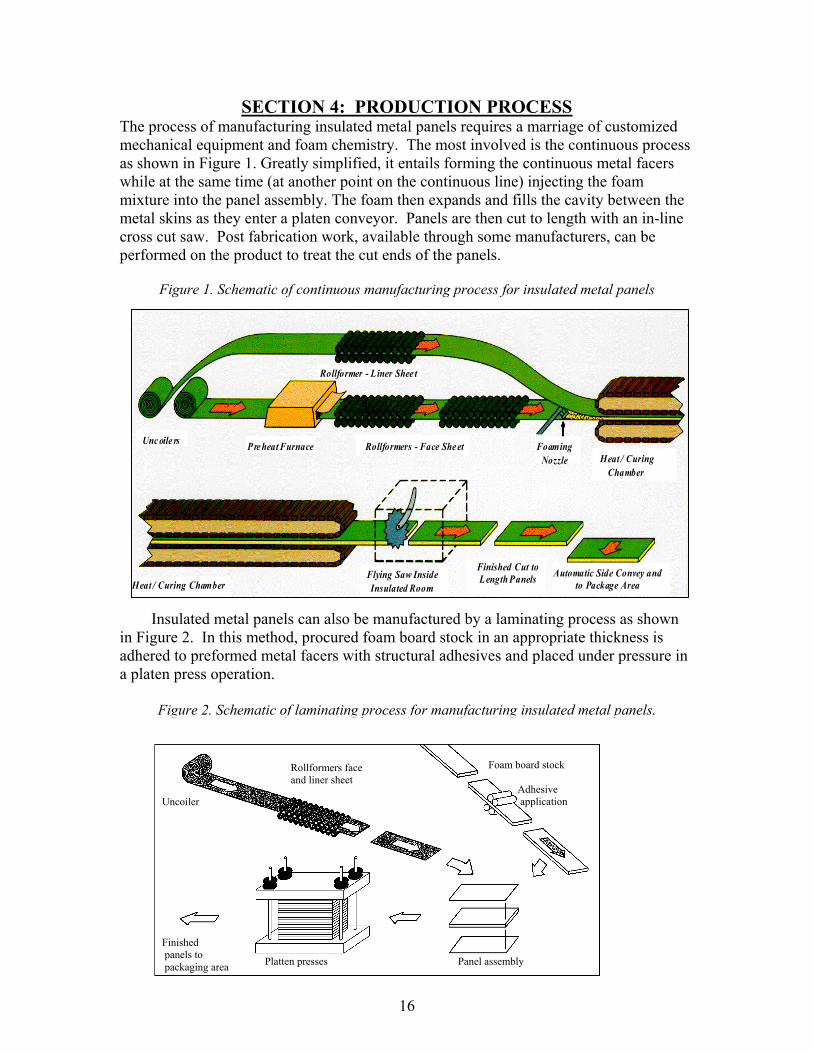
SECTION 4: PRODUCTION PROCESS The process of manufacturing insulated metal panels requires a marriage of customized mechanical equipment and foam chemistry. The most involved is the continuous process as shown in Figure 1. Greatly simplified, it entails forming the continuous metal facers while at the same time (at another point on the continuous line) injecting the foam mixture into the panel assembly. The foam then expands and fills the cavity between the metal skins as they enter a platen conveyor. Panels are then cut to length with an in-line cross cut saw. Post fabrication work, available through some manufacturers, can be performed on the product to treat the cut ends of the panels.
Figure 1. Schematic of continuous manufacturing process for insulated metal panels Insulated metal panels can also be manufactured by a laminating process as shown in Figure 2. In this method, procured foam board stock in an appropriate thickness is adhered to preformed metal facers with structural adhesives and placed under pressure in a platen press operation.
Figure 2. Schematic of laminating process for manufacturing insulated metal panels.
Rollformer - Liner Shee t
Unc oile rs Pre heat Furnace Rollformers - Face She et FoamingFoamingNozzleNozzle Heat / Curing
Chamber
Heat / Curing ChamberFlying Saw InsideInsulated Room
Finished Cut toLength Panels Automatic Side Convey and
to Package Area
Uncoiler Finished panels to packaging area
Foam board stock Adhesive application
Rollformers face and liner sheet
Platten presses Panel assembly

17
Product Description The most common metal substrate for panel faces is G90 galvanized steel. Other substrates are stainless steel, aluminum-zinc coated steel, and aluminum. To stiffen the panel faces an embossed surface texture is commonly applied and various profiles are roll formed into them. Profiles are usually in the form of light striations or planking, deep ribbing or stiffening beads. Smooth or un-embossed surfaces are available as a premium from some manufacturers. Panel edges are roll formed to create interlocking side joints, which accommodate the concealed fastener and clip system and achieve the panel-to-panel seals. A variety of modules, profiles and side joints are available for insulated metal roof systems. For example, side joints can be standing seam, or overlapping as shown in Figure 3. The width of the panel is referred to as the module and can typically range from 24 inches to 42 inches. The panel thickness can vary from 2 inches to 6 inches with R-values generally ranging from 7 to 48 depending on the manufacturer.
Figure 3. Examples of side joints
overlapping
standing seam

18
Most insulated metal wall panels may be oriented either with the length of the panel running vertically or horizontally as shown in Figures 4 and 5.
The panel core is usually a polyisocyanurate or polyurethane foam. The chemistry is usually proprietary to each manufacturer. The formulation contains the additives necessary to meet the fire performance of the given product geometry and to satisfy the needs of the manufacturing process. The density is typically between 2 and 3 pcf. The panel weight will vary depending on thickness and gauge of the skins. A 2-inch panel with 26 gauge skins will weigh about 2.3 psf. The same panel with 22 gauge skins may weigh as much as 3.65 psf depending on the panel profile.
Figure 4. Vertical orientation Figure 5. Horizontal orientation

19
SECTION 5: DESIGN PARAMETERS Thermal Effects All insulated metal panels must demonstrate the ability to withstand exposure to temperature extremes on both the exterior and interior skins. Panel temperatures on the outer skin can reach service temperatures of 180 degrees F with dark colors. The surface temperature can be reduced by using lighter colors and paint systems containing cool infrared reflective pigments. The inner skin is usually limited to a lower in-service temperature. Depending on the manufacturer the maximum allowable liner temperature will range from 120 degrees F to 160 degrees F. It should be noted that panels manufactured in a pinch roll/contact adhesive process usually will not perform well in high temperatures. The minimum interior temperature for cold storage applications can be as low as �–40 degrees F. Thermal expansion is accommodated by a combination of thermal bow and thermal stress. Because insulated metal panels are a composite sandwich with both the interior and exterior faces bonded to the core, there is no significant differential expansion between the interior and exterior faces. The insulated panels are positively fastened to the structure and the expansion of the panel is distributed among the individual spans as thermal bow rather than linear expansion. The overall panel does not significantly elongate or contract so there is no need to install an insulated metal roof panel with slotted clips. Thermal bow does not adversely affect the performance of the panels used in a properly designed roof system, since all panel analysis calculations must make allowance for it. The ability of the insulated panel to accommodate this flexing is substantiated by Cyclic Load Tests, which subject a panel specimen to alternate cycles of positive and negative loads at a deflection limit of L/180. A typical test might use a 10-foot long panel. A cycle load of +/- 20 psf is applied.
Thermal Deflection
Per Job Requirements

20
Metal Roof End Laps As panel lengths are limited by practical concerns such as shipping and handling limitations, it will sometimes be necessary to provide an endlap joint for insulated metal roof panels. Typically, the liner and foam core will be cut away leaving a nominal exterior face extension for a lap over the lower panel. The length of the extension and end lap is dependent on the roof slope and the panel profile. The end lap joints are caulked and fastened according to the roof panel manufacturer�’s recommendations. Metal Roof Slope As with any metal roof, insulated metal roof panels must be installed to a minimum slope. The amount of slope required varies from manufacturer to manufacturer -check IBC for minimum slope requirements for roofs.
Single length panels ¼ inch in 12 inch slope Panels with lap joint ½ inch in 12 inch slope
These minimum slopes should be considered as absolute minimums for warranty considerations. Metal Roof Penetrations Penetrations should be kept to a minimum. Where penetrations are required, small penetrations, such as VTRs, can be sealed with �“boots�” or stack flashings. For larger roof penetrations, a factory-welded curb, with additional structural support, is the best solution.

21
SECTION 6: INSTALLATION While the installation of insulated metal panels is relatively simple when compared to multi-piece field metal systems or built-up roof systems, there are certain very important requirements that must be met. Support Gauge and Alignment Because factory insulated metal panels are strong and rigid the structure they attach to must be held to a closer tolerance than that required for some other systems. If the steel substructure has excessive variation from the theoretical plane, the insulated panels could be subjected to undue stress. This may result in aesthetic changes or diminished load capacity. It is recommended that wall panel attachments should be a minimum of 16 gauge steel designed for an L/180, 1½ inches maximum deflection criteria. Some projects may require tighter criteria when the same framework supports interior treatments such as gypsum wallboard. Fastening into wood is not recommended due to the cyclic fastener rocking caused by the panel�’s reaction to temperature differences of its skins as the sun heats the exterior face. The alignment of the supports is important especially with the most commonly used back seal or liner-side seal systems where the support alignment establishes the final alignment of the wall. In addition, improperly aligned supports can induce stress in the panels and cause face side distortions. Fastener pull out values should be reviewed for each project. The minimum suggested bearing width at purlins is 2 ½ inches. It is necessary to specify steel tolerances and deflections similar to those required for insulated architectural walls. This requirement for steel alignment and deflection limits must be cross-referenced in the structural steel specification to ensure a quality installation. For proper panel installation, the maximum deviation of a girt for industrial applications typically should not be more than 3/8 inch in any 20-foot length in any direction. The support alignment should not deviate more than ± .75 inch from the theoretical girt plane at any point on the wall (thicker panels may require tighter alignment tolerances). For architectural wall or roof applications, the support alignment should not deviate more than ± ¼ inch in any 20-foot length in any direction. The total alignment envelope should be ± ½ inch over the entire panel surface with the exception of transition areas such as building corners and soffit areas where the alignment must be within ± inch of the theoretical girt plane to accommodate formed transition or corner panels. If there is variation in the steel alignment from the theoretical plane, it should all be in an outward direction. If one purlin is on the plus side and the adjacent purlin is on the minus side, this can induce unacceptable stresses in the insulated panels.

22
Example: An insulated roof panel spanning 5 feet with a deflection limit of L/180 will deflect a maximum of 1/3 inch. If the purlin supporting the panel is designed with the deflection limit of L/240 and spans 25 feet, the allowable deflection for the purlin is 1 ¼ inches. This can cause excessive deflection and stress in the insulated panels and in the panel connections. All fundamentals of the system, including fastening details, trim details, and panel joints must be design coordinated to maximize panel performance. The installer of the insulated metal wall and roof panels must check the supporting structure before starting installation. Any variations in excess of those noted above must be corrected prior to starting work or reported to the architect/engineer as soon as possible. Panel Layout Because of the rigidity of the insulated metal wall and roof panels maintaining proper layout and module of the panels is critical for proper installation. Layout and module control is especially important when the length of the roof slope requires an end lap condition or the wall panel requires a stack joint. Panel Trim Trim materials differ with the application and aesthetics desired. For industrial projects press broken trim is quite functional. A 26 gauge minimum thickness can be used when the face skin of the panel is also 26 gauge. To achieve a higher-level architectural presentation with crisper sight lines, extruded trim or a heavier gauge of press formed trim should be specified. (Both types of details are presented in Section 7: Detail Illustrations)

23
Panel Clips and Fasteners To achieve published load values, fasteners and clips as recommended by the manufacturer must be used. Fasteners are as equally important as clips and should be installed according to the manufacturer�’s instructions as verified by the structural calculations. In addition, they should be installed normal to the structure and the panels. They are not to be overdriven nor under driven because either condition can result in leakage. Panel Caulking and Sealants To achieve the noted air and water infiltration performance levels a proper seal system is imperative. The most common technique is the liner side seal network. For non-refrigerated buildings, this involves field applying non-skinning butyl sealant on the structural steel at panel ends and connecting them to either shop or field applied sealant or gaskets located in the panel side joint. The result is that each panel has a complete perimeter of butyl sealant on the liner or warm side, which in turn creates an excellent vapor barrier. At transition areas such as corners or wall to soffit edges, proper liner trim is needed to maintain the liner seal continuity. A major advantage of the liner seal technique is that the critical seals are located away from the face of the panel, and will not cause staining or dirt attraction as occurs with other types of wall panel systems that are faced sealed. It is important that vertical panel systems with a double tongue and groove side joint allow water to weep at the panel base. For weather tightness, most insulated metal roof panels require a concealed bead of sealant on the exterior of the panel side joint. Continuity of panel caulking is critical. All joints and overlaps must be completely caulked to prevent water and air infiltration. Caulking of end lap panel joints is especially critical as the lap occurs in the �“low�” flutes of the panels. Key performance items for inclusion in a guide specification are shown in Addendum 2. Summary Insulated metal panels offer benefits for the entire building team. To reiterate, the owner achieves a thermally efficient, high performance product that has superior life cycle costs. The designer works with a product that offers many design and performance options. The erector works with a product that is easy and quick to install in almost any weather condition, in response to the common tight building schedules of today�’s market. When you consider insulated metal panel products, use the information presented herein as a start to properly promote, specify and detail a project. Additional information is available from the specific manufacturers. Contact the MCA for a list of member manufacturers.

24
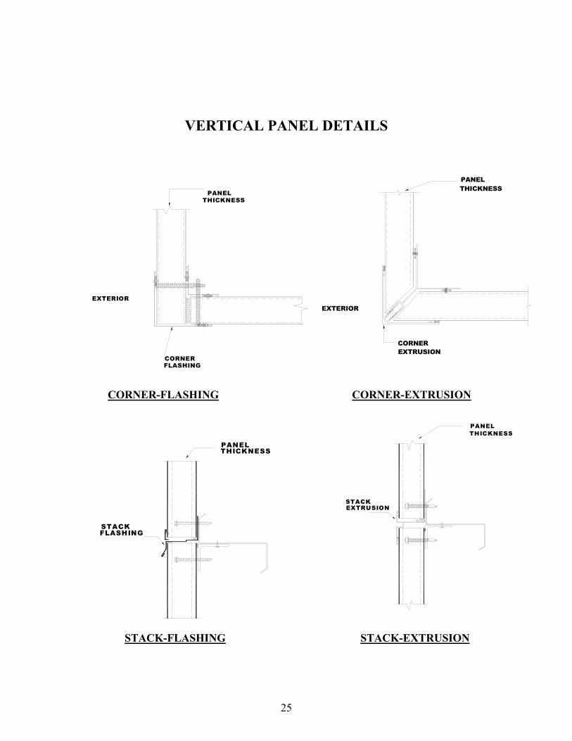
SECTION 7: DETAIL ILLUSTRATIONS The side joints and fastening methods shown on the following details are to be construed as generic and schematic in nature. All references to �“extrusions�” pertain to aluminum extrusions. The different manufacturers have modules, profiles and side joints that are specific to them. For example, side joints can be standing seam, interlocking, or overlapping.
VERTICAL PANEL DETAILS
BASE-EXTRUSION BASE-FLASHING
90° INSIDE CORNER-FLASHING 90° INSIDE CORNER-EXTRUSION
BASEEXTRUSION
PANELTHICKNESS
B A S EF L A S H IN G
P A N E LT H IC K N E S S
25
VERTICAL PANEL DETAILS
CORNER-FLASHING CORNER-EXTRUSION
STACKFLASHING
PANELTHICKNESS
STACKEXTRUSION
PANELTHICKNESS
STACK-FLASHING STACK-EXTRUSION
EXTERIOR
PANELTHICKNESS
CORNERFLASHING
CORNEREXTRUSION
EXTERIOR
PANELTHICKNESS

26
VERTICAL PANEL DETAILS
JAMB-FLASHING JAMB-EXTRUSION
HEADER FLASHING HEADER EXTRUSION
PANEL THICKNESS
JAMBFLASHING
JAMBEXTRUSIONS PANEL
THICKNESS
DOOR HEADER
HEADEREXTRUSION

27
VERTICAL PANEL DETAILS
PARAPET-EXTRUSION PARAPET-FLASHING
PARAPETEXTRUSION
PANELTHICKNESS
METAL CLEAT
PARAPETFLASHING
PANELTHICKNESS
WINDOWSILL
WINDOW SILL

28
HORIZONTAL PANEL DETAILS
BASE EXTRUSION
PANELTHICKNESS
JOINT GASKET
WALL PANEL WALL PANEL
INTERIOR JOINT SEALANT
GASKET SEALANT
(BY OTHERS)
WALL STRUCTURAL
FOUR CORNER JOINT DETAIL HORIZONTAL BASE EXTRUSION
VERTICAL JOINT DETAIL

29
1 '-6 " M A X IM U M6 " M IN U M U MR O O F P U R L IN S
B Y O T H E R S
B U T Y L V A P O RS E A L A N T
B Y O T H E R S
IN T E R IO R R ID G EF L A S H IN G
IN S U L A T IO NL O O S E F IL L
S U R F A C E
P A N E LB E A R IN G
2 1 /2 "M IN U M U M
F L A S H IN GS E A L A N T T A P E
R ID G E F L A S H IN GR ID G E C L O S U R E
M F G . S T A N D A R DF A S T E N E R
RIDGE
RAKE
ROOF PANEL DETAILS
RAKE

30
INSULATED PANEL
BY OTHERSEAVE STRUCTURAL
LOOSE FILL
BY OTHERSINSULATION
LOOSE FILL INSULATIONBY OTHERS
EAVE TRIM
ROOF PANEL
MFG. STANDARDFASTENER
MFG. STANDARDFASTENER
BUTYLSEALANT
BUTYLSEALANT
EAVE
ROOF ENDLAP
Roof Endlap
ROOF PANEL DETAILS

31
ADDENDUM 1: Features, Functions, Benefits
FEATURE FUNCTION BENEFIT Single manufactured unit *Quick erection *Labor cost savings *Shorter project schedule *Minimizes Erector impact *Better in-place quality on product quality Insulated core *Provides good insulation *Energy cost savings and efficiency *Structural core *Long span high load perf. Metal Skins *Provides moisture resistance *Weather integrity *Vapor barrier *Offer design flexibility via *Design options and durability color/coating options *Warranted finish Light Weight *Easy to handle *Minimize labor *Lower dead loads *Material savings *Lighter foundations Concealed attachment *Fasteners protected from *Increased longevity the elements *No rust stains Specific joinery *Allows use of the product *Improved weather integrity in horizontal and/or *Design flexibility/joint vertical positions size and orientation Thermally broken side *Avoids thermal through *Lower energy costs joinery conductivity
*Avoids cold spots

32
ADDENDUM 2: Insulated Metal Panel Guide Specification Bullets
In-Place insulation performance: R value =_______ per ASTM C 1363 at ____ Degrees F Product Structural Performance under Positive and Negative wind loads
Per ASTM E 330 or ASTM E 72 Wind Loads per ASCE 7-per code requirements General Area Loads____psf Corner Area Loads_____psf Maximum Air Infiltration:
.06 cfm/ft2 per 6.24 psf per ASTM E 283 .04cfm1 Water Infiltration:
Tested at a minimum pressure of 6.24 psf Per ASTM E 331 Fire: Certified and compliant with Chapter 26 of the controlling
Building code. Evidence of testing required. Support System Alignment/Architectural
¼ inch per 20 feet in any direction, ± .5 inches max, .125 inch in corners OR Support System Alignment/Industrial
3/8 inch per 20 feet in any direction, ± .75 inch max Trim: _____gauge min. press formed trim required
OR Trim: Extruded Trim required
Service Temperatures
180 deg F maximum face Temp ___ deg F maximum liner Temp ___ deg F minimum liner Temp
Core Properties Density: ASTM D 1622 Tensile Strength: ASTM D 1623 Compressive Strength: ASTM D 1621 Shear Strength: ASTM E 72 or ASTM C273 Finishes: Type/PVDF
Warranty Performance levels (see supplier info)
1 Comply with the version of ASHRAE 90.1 Standard that is effective in local jurisdiction. For example, ASHRAE 90.1 -2010 standard will require assemblies of materials and components (sealants, tapes, etc.) that have an average air leakage not to exceed 0.04 cfm/ft2 under a pressure differential of 0.3�” w.g. (1.57psf) (0.2 L/s.m2 @ 75 Pa) when tested in accordance with ASTM E 2357 ASTM E 1677, ASTM E 1680 or ASTM E283; The following assemblies meet the requirements of 5.4.3.1.3 b. (http://www.energysavers.gov/your_home/insulation_airsealing/index.cfm/mytopic=11600) At the time of printing this manual, these numbers are per ASHRAE and anticipated ASHRAE 20b, check with your engineer for current Maximum Air Infiltrations