Instrument cluster (2005) - 2005-2010 Jeep Grand - · PDF fileInstrument cluster (2005) ......
39
Instrument cluster (2005) The instrument cluster (3) for this model is an ElectroMechanical Instrument Cluster (EMIC) that is located in the instrument panel above the steering column opening, directly in front of the driver. The remainder of the EMIC, including the mounts and the electrical connections, are concealed within the instrument panel below the cluster hood (1). The instrument cluster for this model also includes the hardware and software necessary to serve as the electronic body control module and is sometimes referred to as the Cab Compartment Node or CCN. Besides analog gauges and indicators, the EMIC module incorporates two blue-green digital Organic Light Emitting Diode (OLED) display units. One is a fixed segment unit for displaying odometer information, automatic transmission gear selector position (PRNDL), and the cruise indicator. The second is a large, reconfigurable dot matrix unit which serves as the visual display and interface for the Electronic Vehicle Information Center (EVIC), the trip computer, the Universal Garage Door Opener (UGDO), the customer programmable features, numerous textual warning or reminder indicators and certain diagnostic information. The EMIC gauges and indicators are visible in a dedicated opening in the instrument panel below the cluster hood and are protected by a clear plastic cluster lens and integral hood unit (3). The cluster hood serves as a visor and shields the face of the cluster from ambient light and reflections to reduce glare. The molded plastic lens and hood has a number of integral latch features that secure it to tabs molded into the outer perimeter of the cluster housing. The lens and hood unit also has two integral mounting tabs on the top of the unit. These mounting tabs combined with two on the top of the cluster housing are used to secure the top of the EMIC to the molded plastic instrument panel cluster carrier with two screws. The rear of the cluster housing (5) and the EMIC electronic circuitry are protected by a molded plastic rear cover (1), which is also secured to the cluster housing by integral latch features. The rear cover includes clearance holes for the cluster connector receptacles. The connector receptacles on the back of the cluster electronic circuit board connect the EMIC to the vehicle electrical system through three take outs with connectors from the instrument panel wire harness. Sandwiched between the rear cover and the lens and hood unit is the cluster housing. The molded plastic cluster housing serves as the carrier for the cluster circuit board and circuitry, the cluster connector receptacles, the major (4) and minor (2) gauges, a Light Emitting Diode (LED) for each cluster
Transcript of Instrument cluster (2005) - 2005-2010 Jeep Grand - · PDF fileInstrument cluster (2005) ......
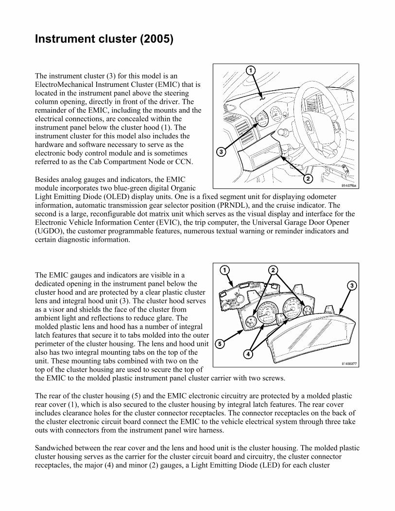
Instrument cluster (2005) The instrument cluster (3) for this model is an ElectroMechanical Instrument Cluster (EMIC) that is located in the instrument panel above the steering column opening, directly in front of the driver. The remainder of the EMIC, including the mounts and the electrical connections, are concealed within the instrument panel below the cluster hood (1). The instrument cluster for this model also includes the hardware and software necessary to serve as the electronic body control module and is sometimes referred to as the Cab Compartment Node or CCN.
Besides analog gauges and indicators, the EMIC module incorporates two blue-green digital Organic Light Emitting Diode (OLED) display units. One is a fixed segment unit for displaying odometer information, automatic transmission gear selector position (PRNDL), and the cruise indicator. The second is a large, reconfigurable dot matrix unit which serves as the visual display and interface for the Electronic Vehicle Information Center (EVIC), the trip computer, the Universal Garage Door Opener (UGDO), the customer programmable features, numerous textual warning or reminder indicators and certain diagnostic information.
The EMIC gauges and indicators are visible in a dedicated opening in the instrument panel below the cluster hood and are protected by a clear plastic cluster lens and integral hood unit (3). The cluster hood serves as a visor and shields the face of the cluster from ambient light and reflections to reduce glare. The molded plastic lens and hood has a number of integral latch features that secure it to tabs molded into the outer perimeter of the cluster housing. The lens and hood unit also has two integral mounting tabs on the top of the unit. These mounting tabs combined with two on the top of the cluster housing are used to secure the top of the EMIC to the molded plastic instrument panel cluster carrier with two screws.
The rear of the cluster housing (5) and the EMIC electronic circuitry are protected by a molded plastic rear cover (1), which is also secured to the cluster housing by integral latch features. The rear cover includes clearance holes for the cluster connector receptacles. The connector receptacles on the back of the cluster electronic circuit board connect the EMIC to the vehicle electrical system through three take outs with connectors from the instrument panel wire harness.
Sandwiched between the rear cover and the lens and hood unit is the cluster housing. The molded plastic cluster housing serves as the carrier for the cluster circuit board and circuitry, the cluster connector receptacles, the major (4) and minor (2) gauges, a Light Emitting Diode (LED) for each cluster
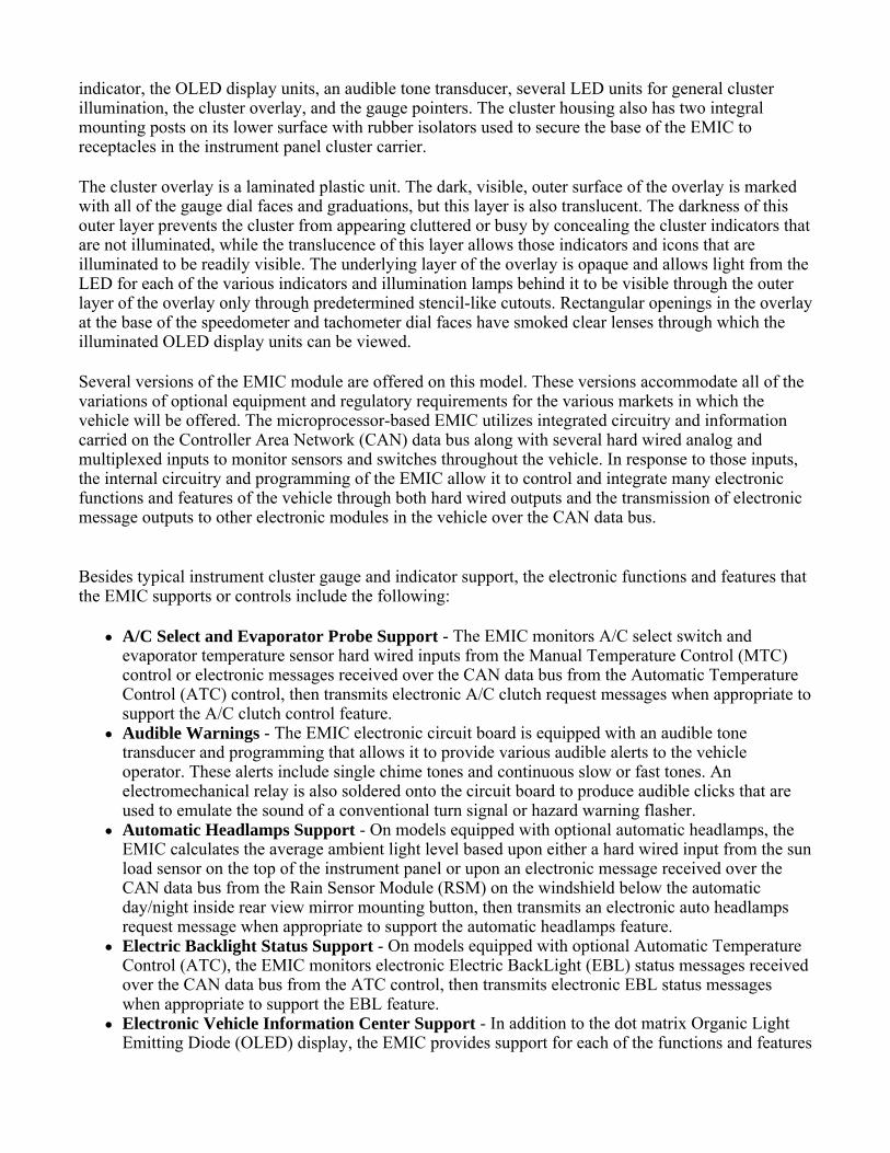
indicator, the OLED display units, an audible tone transducer, several LED units for general cluster illumination, the cluster overlay, and the gauge pointers. The cluster housing also has two integral mounting posts on its lower surface with rubber isolators used to secure the base of the EMIC to receptacles in the instrument panel cluster carrier.
The cluster overlay is a laminated plastic unit. The dark, visible, outer surface of the overlay is marked with all of the gauge dial faces and graduations, but this layer is also translucent. The darkness of this outer layer prevents the cluster from appearing cluttered or busy by concealing the cluster indicators that are not illuminated, while the translucence of this layer allows those indicators and icons that are illuminated to be readily visible. The underlying layer of the overlay is opaque and allows light from the LED for each of the various indicators and illumination lamps behind it to be visible through the outer layer of the overlay only through predetermined stencil-like cutouts. Rectangular openings in the overlay at the base of the speedometer and tachometer dial faces have smoked clear lenses through which the illuminated OLED display units can be viewed.
Several versions of the EMIC module are offered on this model. These versions accommodate all of the variations of optional equipment and regulatory requirements for the various markets in which the vehicle will be offered. The microprocessor-based EMIC utilizes integrated circuitry and information carried on the Controller Area Network (CAN) data bus along with several hard wired analog and multiplexed inputs to monitor sensors and switches throughout the vehicle. In response to those inputs, the internal circuitry and programming of the EMIC allow it to control and integrate many electronic functions and features of the vehicle through both hard wired outputs and the transmission of electronic message outputs to other electronic modules in the vehicle over the CAN data bus.
Besides typical instrument cluster gauge and indicator support, the electronic functions and features that the EMIC supports or controls include the following:
A/C Select and Evaporator Probe Support - The EMIC monitors A/C select switch and evaporator temperature sensor hard wired inputs from the Manual Temperature Control (MTC) control or electronic messages received over the CAN data bus from the Automatic Temperature Control (ATC) control, then transmits electronic A/C clutch request messages when appropriate to support the A/C clutch control feature.
Audible Warnings - The EMIC electronic circuit board is equipped with an audible tone transducer and programming that allows it to provide various audible alerts to the vehicle operator. These alerts include single chime tones and continuous slow or fast tones. An electromechanical relay is also soldered onto the circuit board to produce audible clicks that are used to emulate the sound of a conventional turn signal or hazard warning flasher.
Automatic Headlamps Support - On models equipped with optional automatic headlamps, the EMIC calculates the average ambient light level based upon either a hard wired input from the sun load sensor on the top of the instrument panel or upon an electronic message received over the CAN data bus from the Rain Sensor Module (RSM) on the windshield below the automatic day/night inside rear view mirror mounting button, then transmits an electronic auto headlamps request message when appropriate to support the automatic headlamps feature.
Electric Backlight Status Support - On models equipped with optional Automatic Temperature Control (ATC), the EMIC monitors electronic Electric BackLight (EBL) status messages received over the CAN data bus from the ATC control, then transmits electronic EBL status messages when appropriate to support the EBL feature.
Electronic Vehicle Information Center Support - In addition to the dot matrix Organic Light Emitting Diode (OLED) display, the EMIC provides support for each of the functions and features
of the Electronic Vehicle Information Center (EVIC). This includes support for the compass, customer programmable features, textual warnings, Tire Pressure Monitor (TPM), trip computer, Universal Garage Door Opener (UGDO) and the upper instrument panel switch pod inputs that are used to control and configure many of the EVIC displays. This also includes display arbitrator programming, which controls the priorities, sequences, and transition of information that is displayed in the EVIC, particularly when multiple display requests are received simultaneously.
Enhanced Accident Response Support - The EMIC monitors an input from the Occupant Restraint Controller (ORC) and, following an airbag deployment, will immediately disable the power lock relay output, unlock all doors by activating the power unlock relay output, then enables the power lock relay output if the power lock switch input remains inactive for two seconds. The EMIC also monitors an input from the Powertrain Control Module (PCM) to automatically turn on the interior lighting after an airbag deployment event, ten seconds after the vehicle speed is zero. The interior lighting remains illuminated until the ignition switch is turned to the Off position, at which time the interior lighting returns to normal operation and control. These Enhanced Accident Response System (EARS) features are each dependent upon a functional vehicle electrical system following the vehicle impact event.
Fuel Level Data Support - The EMIC provides a current source for and receives a hard wired analog input from the fuel level sending unit located on the fuel pump module in the fuel tank. The EMIC uses this input to calculate the proper fuel gauge needle position and to control low fuel indicator operation. Based upon this input, the EMIC also uses electronic messaging to transmit this data over the CAN data bus for use by other electronic modules in the vehicle.
Heated Seat Switch Support and Switch Indicator Control - On models equipped with optional heated seats, the EMIC monitors hard wired inputs from the heated seat switches in the lower instrument panel switch pod and transmits electronic heated seat request messages over the CAN data bus. This message wakes up the Heated Seat Module (HSM) when the switch is actuated. The EMIC then monitors electronic messages received over the CAN data bus from the HSM to control a high side driver output to the appropriate heated seat switch Light Emitting Diode (LED) indicators.
Ignition On and Ignition Accessory/On Relay Control - The EMIC monitors hard wired inputs from the ignition switch on the instrument panel, and provides low side driver outputs to control both the ignition On and ignition Accessory/On relays in the Junction Block (JB) as appropriate.
Interior Lamp Load Shedding - The EMIC provides a battery saver feature which will automatically turn off all interior lamps if they remain on after a timed interval of about eight minutes.
Interior Lighting Control - The EMIC monitors electronic messages and hard wired inputs from the interior lighting switch, the door ajar switches, the liftgate ajar switch, the liftgate flip-up glass ajar switch, the reading lamp switches, and the Sentry Key REmote Entry Module (SKREEM) to provide courtesy lamp control. This includes support for timed illuminated entry with theater-style fade-to-off and courtesy illumination defeat features.
Panel Lamps Dimming Control - The EMIC monitors electronic dimming level messages received from the panel lamps dimmer switch input to the Steering Control Module (SCM) over the CAN data bus, then provides a hard wired 12-volt Pulse-Width Modulated (PWM) output that synchronizes the dimming level of all panel lamps dimmer controlled lamps with that of the cluster general illumination lighting.
Park Assist Switch Support and Switch Indicator Control - On models equipped with the optional park assist system, the EMIC monitors a hard wired input from the park assist switch in the lower instrument panel switch pod and transmits electronic park assist switch status messages over the CAN data bus. This message tells the park assist module whether the system should be enabled or disabled when the switch is actuated. The EMIC then monitors electronic messages received over the CAN data bus from the park assist module to control a high side driver output to the park assist switch Light Emitting Diode (LED) disable indicator.
Power Lock System Control - The EMIC monitors inputs from the power lock switches and the Sentry Key REmote Entry Module (SKREEM) to provide control of the power lock motors through high side driver outputs to the door lock and unlock relays. This includes support for rolling door locks (also known as automatic door locks), automatic door unlock, and a door lock inhibit mode.
Remote Keyless Entry Support - The EMIC supports the Remote Keyless Entry (RKE) system features, including support for the RKE Lock, Unlock (with optional driver-door-only unlock, and unlock-all-doors), Panic, audible chirp, optical chirp, illuminated entry modes, an RKE programming mode, as well as optional Vehicle Theft Security System (VTSS) arming (when the proper VTSS arming conditions are met) and disarming.
Vehicle Theft Security System Control - The EMIC monitors inputs from the door ajar switches, the Steering Control Module (SCM), the Sentry Key REmote Entry Module (SKREEM) and, on vehicles so equipped, the intrusion module then provides electronic horn and/or lighting request messages to the Front Control Module (FCM) located on the Integrated Power Module (IPM) for the appropriate VTSS alarm output features.
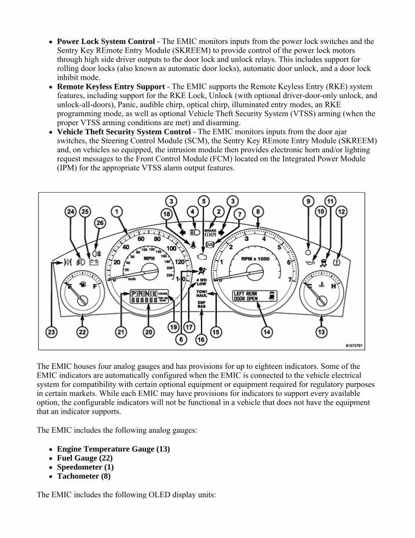
The EMIC houses four analog gauges and has provisions for up to eighteen indicators. Some of the EMIC indicators are automatically configured when the EMIC is connected to the vehicle electrical system for compatibility with certain optional equipment or equipment required for regulatory purposes in certain markets. While each EMIC may have provisions for indicators to support every available option, the configurable indicators will not be functional in a vehicle that does not have the equipment that an indicator supports.
The EMIC includes the following analog gauges:
Engine Temperature Gauge (13) Fuel Gauge (22) Speedometer (1) Tachometer (8)
The EMIC includes the following OLED display units:

Fixed Segment Display - Includes Gear Selector Indicator (21), Odometer (20) & Cruise Indicator (19)
Dot Matrix Display (14) - Electronic Vehicle Information Center (EVIC), Trip Odometer A & B, Textual Messages
The EMIC includes provisions for the following indicators:
Adjustable Pedal System Indicator - textual messages in dot matrix display (14) Airbag Indicator (6) Ajar Indicators - textual messages and icon in dot matrix display (14) for doors, hood, liftgate
and liftgate flip-up glass Antilock Brake System (ABS) Indicator (7) - and textual message in dot matrix display (14) Brake Indicator (2) Charging Indicator (25) Check Gas Cap Indicator - textual message in dot matrix display (14) Check Gauges Indicator - textual message in dot matrix display (14) Check Shift Procedure Indicator - textual message in dot matrix display (14) Coolant Low Indicator - textual message and icon in dot matrix display (14) Cruise Indicator (19) - text in fixed segment display Electronic Throttle Control (ETC) Indicator (23) Electronic Stability Program (ESP)/Brake Assist System (BAS) Indicator (16) - and textual
messages in dot matrix display (14) Four-Wheel Drive Low Indicator (17) Four-Wheel Drive System In Neutral Indicator - textual message and icon in dot matrix
display (14) Front Fog Lamp Indicator (24) High Beam Indicator (4) Low Brake Fluid Level Indicator - textual message in dot matrix display (14) Low Fuel Indicator - textual message and icon in dot matrix display (14) Low Oil Pressure Indicator (10) Malfunction Indicator Lamp (MIL) (5) Memory System Indicator - textual messages in dot matrix display (14) Park Assist Disabled Indicator - textual message in dot matrix display (14) Perform Service Indicator - textual message in dot matrix display (14) Rear Fog Lamp Indicator (26) Seat Belt Indicator (18) Security Indicator (9) - also textual messages for Sentry Key Immobilizer System (SKIM) in dot
matrix display (14) Service Column Lock Indicator - textual message in dot matrix display (14) Service Four-Wheel Drive System Indicator - textual message in dot matrix display (14) Service Park Assist System Indicator - textual message in dot matrix display (14) Smart (Auto High) Beam Indicator - textual messages in dot matrix display (14) Tire Pressure Monitor (TPM) Indicator (12) - and/or textual messages in dot matrix display
(14) Tow/Haul Indicator (15) Traction Control/Electronic Stability Program (ESP) Indicator (11) - and textual messages in
dot matrix display (14) Transmission Overtemp Indicator - textual message in dot matrix display (14) Turn Signal (Right and Left) Indicators (3) Turn-Signal-On Reminder Indicator - textual message and icon in dot matrix display (14) Washer Fluid Indicator - textual message and icon in dot matrix display (14)

Wait-To-Start Indicator - textual message and icon in dot matrix display (14) Water-In-Fuel Indicator - textual message in dot matrix display (14)
Each indicator in the EMIC, except those located within an OLED display unit, is illuminated by a dedicated LED that is soldered onto the EMIC electronic circuit board. Cluster illumination is accomplished by several dimmable LED units, which illuminate each of the gauge dial faces for visibility when the exterior lighting is turned on. These LED units are not available for service replacement and, if damaged or faulty, the entire EMIC must be replaced.
Hard wired circuitry connects the EMIC to the electrical system of the vehicle. These hard wired circuits are integral to several wire harnesses, which are routed throughout the vehicle and retained by many different methods. These circuits may be connected to each other, to the vehicle electrical system and to the EMIC through the use of a combination of soldered splices, splice block connectors, and many different types of wire harness terminal connectors and insulators. Refer to the appropriate wiring information. The wiring information includes wiring diagrams, proper wire and connector repair procedures, further details on wire harness routing and retention, as well as pin-out and location views for the various wire harness connectors, splices and grounds.
The EMIC module for this model is serviced only as a complete unit. The EMIC module cannot be adjusted or repaired. If a gauge, an LED unit, an OLED display unit, the electronic circuit board, the circuit board hardware, the cluster overlay, or the EMIC housing are damaged or faulty, the entire EMIC module must be replaced. The cluster lens, hood and mask unit is available for separate service replacement.
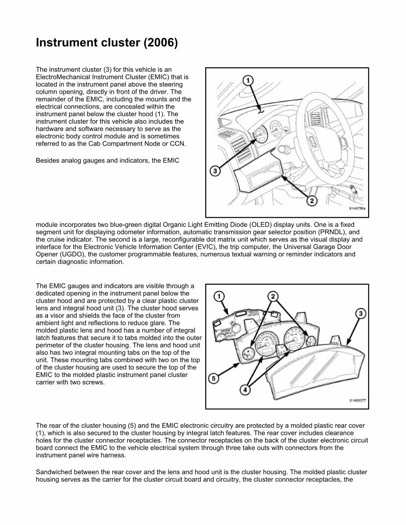
Instrument cluster (2006) The instrument cluster (3) for this vehicle is an ElectroMechanical Instrument Cluster (EMIC) that is located in the instrument panel above the steering column opening, directly in front of the driver. The remainder of the EMIC, including the mounts and the electrical connections, are concealed within the instrument panel below the cluster hood (1). The instrument cluster for this vehicle also includes the hardware and software necessary to serve as the electronic body control module and is sometimes referred to as the Cab Compartment Node or CCN.
Besides analog gauges and indicators, the EMIC
module incorporates two blue-green digital Organic Light Emitting Diode (OLED) display units. One is a fixed segment unit for displaying odometer information, automatic transmission gear selector position (PRNDL), and the cruise indicator. The second is a large, reconfigurable dot matrix unit which serves as the visual display and interface for the Electronic Vehicle Information Center (EVIC), the trip computer, the Universal Garage Door Opener (UGDO), the customer programmable features, numerous textual warning or reminder indicators and certain diagnostic information.
The EMIC gauges and indicators are visible through a dedicated opening in the instrument panel below the cluster hood and are protected by a clear plastic cluster lens and integral hood unit (3). The cluster hood serves as a visor and shields the face of the cluster from ambient light and reflections to reduce glare. The molded plastic lens and hood has a number of integral latch features that secure it to tabs molded into the outer perimeter of the cluster housing. The lens and hood unit also has two integral mounting tabs on the top of the unit. These mounting tabs combined with two on the top of the cluster housing are used to secure the top of the EMIC to the molded plastic instrument panel cluster carrier with two screws.
The rear of the cluster housing (5) and the EMIC electronic circuitry are protected by a molded plastic rear cover (1), which is also secured to the cluster housing by integral latch features. The rear cover includes clearance holes for the cluster connector receptacles. The connector receptacles on the back of the cluster electronic circuit board connect the EMIC to the vehicle electrical system through three take outs with connectors from the instrument panel wire harness.
Sandwiched between the rear cover and the lens and hood unit is the cluster housing. The molded plastic cluster housing serves as the carrier for the cluster circuit board and circuitry, the cluster connector receptacles, the

major (4) and minor (2) gauges, a Light Emitting Diode (LED) for each cluster indicator, the two OLED display units, an audible tone transducer, several LED units for general cluster illumination, the cluster overlay, and the gauge pointers. The cluster housing also has two integral mounting posts on its lower surface with rubber isolators used to secure the base of the EMIC to receptacles in the instrument panel cluster carrier.
The cluster overlay is a laminated plastic unit. The dark, visible, outer surface of the overlay is marked with all of the gauge dial faces and graduations, but this layer is also translucent. The darkness of this outer layer prevents the cluster from appearing cluttered or busy by concealing the cluster indicators that are not illuminated, while the translucence of this layer allows those indicators and icons that are illuminated to be readily visible. The underlying layer of the overlay is opaque and allows light from the LED for each of the various indicators and illumination lamps behind it to be visible through the outer layer of the overlay only through predetermined stencil-like cutouts. Rectangular openings in the overlay at the base of the speedometer and tachometer dial faces have smoked clear lenses through which the illuminated OLED display units can be viewed.
Several versions of the EMIC module are offered on this vehicle. These versions accommodate all of the variations of optional equipment and regulatory requirements for the various markets in which the vehicle is offered. The microprocessor-based EMIC utilizes integrated circuitry and information carried on the Controller Area Network (CAN) data bus along with several hard wired analog and multiplexed inputs to monitor sensors and switches throughout the vehicle. In response to those inputs, the internal circuitry and programming of the EMIC allow it to control and integrate many electronic functions and features of the vehicle through both hard wired outputs and the transmission of electronic message outputs to other electronic modules in the vehicle over the CAN data bus.
Besides typical instrument cluster gauge and indicator support, the electronic functions and features that the EMIC supports or controls include the following:
A/C Select and Evaporator Probe Support - The EMIC monitors A/C select switch and evaporator temperature sensor hard wired inputs from the Manual Temperature Control (MTC) control or electronic messages received over the CAN data bus from the Automatic Temperature Control (ATC) control, then transmits electronic A/C clutch request messages when appropriate to support the A/C clutch control feature.
Audible Warnings - The EMIC electronic circuit board is equipped with an audible tone transducer and programming that allows it to provide various audible alerts to the vehicle operator. These alerts include single chime tones and continuous slow or fast tones. An electromechanical relay is also soldered onto the circuit board to produce audible clicks that are used to emulate the sound of a conventional turn signal or hazard warning flasher.
Automatic Headlamps Support - On vehicles equipped with optional automatic headlamps, the EMIC calculates the average ambient light level based upon either a hard wired input from the sun load sensor on the top of the instrument panel or upon an electronic message received over the CAN data bus from the Rain Sensor Module (RSM) on the windshield below the automatic day/night inside rear view mirror mounting button, then transmits an electronic auto headlamps request message when appropriate to support the automatic headlamps feature.
Electric Backlight Status Support - On vehicles equipped with optional Automatic Temperature Control (ATC), the EMIC monitors electronic Electric BackLight (EBL) status messages received over the CAN data bus from the ATC control, then transmits electronic EBL status messages when appropriate to support the EBL feature.
Electronic Vehicle Information Center Support - In addition to the dot matrix Organic Light Emitting Diode (OLED) display, the EMIC provides support for each of the functions and features of the Electronic Vehicle Information Center (EVIC). This includes support for the compass, customer programmable features, textual warnings, Tire Pressure Monitor (TPM), trip computer, Universal Garage Door Opener (UGDO) and the upper instrument panel switch pod inputs that are used to control and configure many of the EVIC displays. This also includes display arbitrator programming, which controls the priorities, sequences, and transition of information that is displayed in the EVIC, particularly when multiple display requests are received simultaneously.
Enhanced Accident Response Support - The EMIC monitors an input from the Occupant Restraint Controller (ORC) and, following an airbag deployment, will immediately disable the power lock relay output, unlock all doors by activating the power unlock relay output, then enables the power lock relay output if the power lock switch input remains inactive for two seconds. The EMIC also monitors an input from the Powertrain Control Module (PCM) to automatically turn ON the interior lighting after an airbag deployment

event, 10 seconds after the vehicle speed is zero. The interior lighting remains illuminated until the ignition switch is turned to the OFF position, at which time the interior lighting returns to normal operation and control. These Enhanced Accident Response System (EARS) features are each dependent upon a functional vehicle electrical system following the vehicle impact event.
Fuel Level Data Support - The EMIC provides a current source for and receives a hard wired analog input from the fuel level sending unit located on the fuel pump module in the fuel tank. The EMIC uses this input to calculate the proper fuel gauge needle position and to control low fuel indicator operation. Based upon this input, the EMIC also uses electronic messaging to transmit this data over the CAN data bus for use by other electronic modules in the vehicle.
Heated Seat Switch Support and Switch Indicator Control - On vehicles equipped with optional heated seats, the EMIC monitors hard wired inputs from the heated seat switches in the lower instrument panel switch pod and transmits electronic heated seat request messages over the CAN data bus. This message wakes up the Heated Seat Module (HSM) when the switch is actuated. The EMIC then monitors electronic messages received over the CAN data bus from the HSM to control a high side driver output to the appropriate heated seat switch Light Emitting Diode (LED) indicators.
Ignition On and Ignition Accessory/On Relay Control - The EMIC monitors hard wired inputs from the ignition switch on the instrument panel, and provides low side driver outputs to control both the ignition ON and ignition ACCESSORY/ON relays in the Junction Block (JB) as appropriate.
Interior Lamp Load Shedding - The EMIC provides a battery saver feature which will automatically turn OFF all interior lamps if they remain ON after a timed interval of about eight minutes.
Interior Lighting Control - The EMIC monitors electronic messages and hard wired inputs from the interior lighting switch, the door ajar switches, the liftgate ajar switch, the liftgate flip-up glass ajar switch, the reading lamp switches, and the Sentry Key REmote Entry Module (SKREEM) (also known as the Wireless Control Module/WCM) to provide courtesy lamp control. This includes support for timed illuminated entry with theater-style fade-to-OFF and courtesy illumination DEFEAT features.
Panel Lamps Dimming Control - The EMIC monitors electronic dimming level messages received from the panel lamps dimmer switch input to the Steering Control Module (SCM) over the CAN data bus, then provides a hard wired 12-volt Pulse-Width Modulated (PWM) output that synchronizes the dimming level of all panel lamps dimmer controlled lamps with that of the cluster general illumination lighting.
Park Assist Switch Support and Switch Indicator Control - On vehicles equipped with the optional park assist system, the EMIC monitors a hard wired input from the park assist switch in the lower instrument panel switch pod and transmits electronic park assist switch status messages over the CAN data bus. This message tells the park assist module whether the system should be enabled or disabled when the switch is actuated. The EMIC then monitors electronic messages received over the CAN data bus from the park assist module to control a high side driver output to the park assist switch Light Emitting Diode (LED) disable indicator.
Power Lock System Control - The EMIC monitors inputs from the power lock switches and the Sentry Key REmote Entry Module (SKREEM) (also known as the Wireless Control Module/WCM) to provide control of the power lock motors through high side driver outputs to the door lock and unlock relays. This includes support for rolling door locks (also known as automatic door locks), automatic door unlock, and a door lock inhibit mode.
Remote Keyless Entry Support - The EMIC supports the Remote Keyless Entry (RKE) system features, including support for the RKE LOCK, UNLOCK (with optional driver-door-only unlock, and unlock-all-doors), PANIC, audible chirp, optical chirp, illuminated entry modes, an RKE programming mode, as well as optional Vehicle Theft Security System (VTSS) arming (when the proper VTSS arming conditions are met) and disarming.
Vehicle Theft Security System Control - The EMIC monitors inputs from the door ajar switches, the Steering Control Module (SCM), the Sentry Key REmote Entry Module (SKREEM) (also known as the Wireless Control Module/WCM) and, on vehicles so equipped, the intrusion module then provides electronic horn and lighting request messages to the Front Control Module (FCM) located on the Integrated Power Module (IPM) for the appropriate VTSS alarm output features.
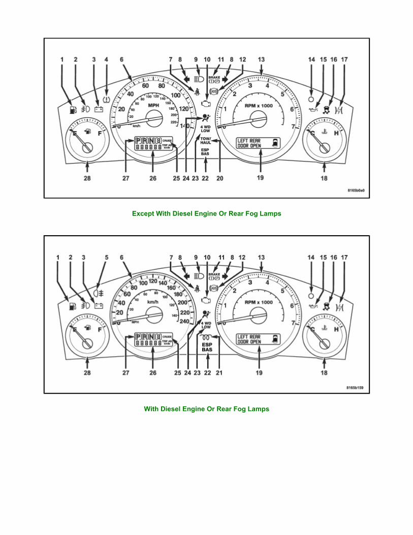
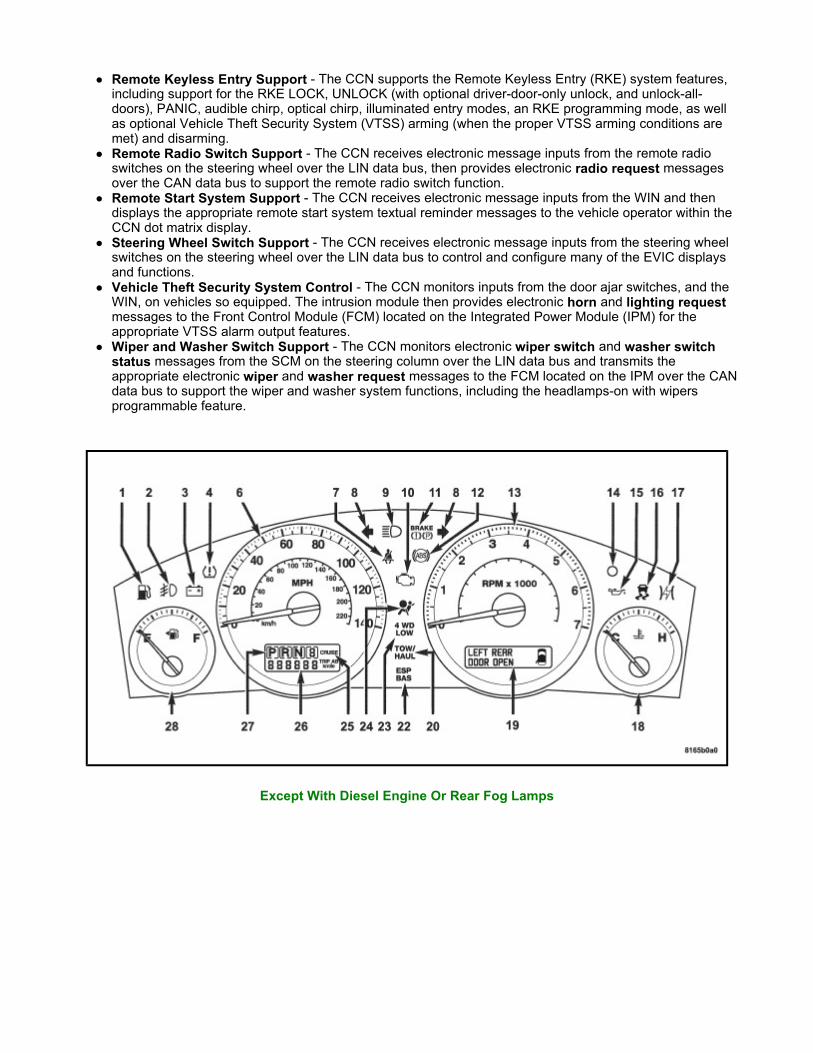
Except With Diesel Engine Or Rear Fog Lamps
With Diesel Engine Or Rear Fog Lamps
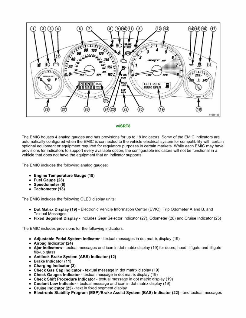
The EMIC houses 4 analog gauges and has provisions for up to 18 indicators. Some of the EMIC indicators are automatically configured when the EMIC is connected to the vehicle electrical system for compatibility with certain optional equipment or equipment required for regulatory purposes in certain markets. While each EMIC may have provisions for indicators to support every available option, the configurable indicators will not be functional in a vehicle that does not have the equipment that an indicator supports.
The EMIC includes the following analog gauges:
Engine Temperature Gauge (18) Fuel Gauge (28) Speedometer (6) Tachometer (13)
The EMIC includes the following OLED display units:
Dot Matrix Display (19) - Electronic Vehicle Information Center (EVIC), Trip Odometer A and B, and Textual Messages
Fixed Segment Display - Includes Gear Selector Indicator (27), Odometer (26) and Cruise Indicator (25)
The EMIC includes provisions for the following indicators:
Adjustable Pedal System Indicator - textual messages in dot matrix display (19) Airbag Indicator (24) Ajar Indicators - textual messages and icon in dot matrix display (19) for doors, hood, liftgate and liftgate
flip-up glass Antilock Brake System (ABS) Indicator (12) Brake Indicator (11) Charging Indicator (3) Check Gas Cap Indicator - textual message in dot matrix display (19) Check Gauges Indicator - textual message in dot matrix display (19) Check Shift Procedure Indicator - textual message in dot matrix display (19) Coolant Low Indicator - textual message and icon in dot matrix display (19) Cruise Indicator (25) - text in fixed segment display Electronic Stability Program (ESP)/Brake Assist System (BAS) Indicator (22) - and textual messages
w/SRT8

in dot matrix display (19) Electronic Throttle Control (ETC) Indicator (17) Four-Wheel Drive Low Indicator (23) Four-Wheel Drive System In Neutral Indicator - textual message and icon in dot matrix display (19) Front Fog Lamp Indicator (2) Gear Selector Indicator (27) High Beam Indicator (9) Low Brake Fluid Level Indicator - textual message in dot matrix display (19) Low Fuel Indicator (1) Low Oil Pressure Indicator (15) Malfunction Indicator Lamp (MIL) (10) Memory System Indicator - textual messages in dot matrix display (19) Oil Pressure Indicator (SRT8 only) - textual message and icon in dot matrix display (19) Oil Temperature Indicator (SRT8 only) - textual message and icon in dot matrix display (19) Park Assist Disabled Indicator - textual message in dot matrix display (19) Perform Service Indicator - textual message in dot matrix display (19) Rear Fog Lamp Indicator (5) - in markets where rear fog lamps are available only Seat Belt Indicator (7) Security Indicator (14) - also textual messages for Sentry Key Immobilizer System (SKIS) in dot matrix
display (19) Service Column Lock Indicator - textual message in dot matrix display (19) Service Exhaust Indicator - textual message in dot matrix display (19) with diesel only Service Four-Wheel Drive System Indicator - textual message in dot matrix display (19) Service Park Assist System Indicator - textual message in dot matrix display (19) SmartBeam® (Auto High Beam) Indicator - textual messages in dot matrix display (19) Tire Pressure Monitor (TPM) Indicator (4) - may also include textual messages in dot matrix display (19) Tow/Haul Indicator (20) Traction Control/Electronic Stability Program (ESP) Indicator (16) Transmission Overtemp Indicator - textual message in dot matrix display (19) Turn-Signal-On Reminder Indicator - textual message and icon in dot matrix display (19) Turn Signal (Right and Left) Indicators (8) Upshift Indicator (SRT8 only) - textual message and icon in dot matrix display (19) Wait-To-Start Indicator (21) - with diesel only Washer Fluid Indicator - textual message and icon in dot matrix display (19) Water-In-Fuel Indicator - textual message in dot matrix display (19) with diesel only
Each indicator in the EMIC, except those located within an OLED display unit, is illuminated by a dedicated LED that is soldered onto the EMIC electronic circuit board. Cluster illumination is accomplished by several dimmable LED units, which illuminate each of the gauge dial faces for visibility when the exterior lighting is turned ON. These LED units are not available for service replacement and, if damaged or ineffective, the entire EMIC must be replaced.
Hard wired circuitry connects the EMIC to the electrical system of the vehicle. These hard wired circuits are integral to several wire harnesses, which are routed throughout the vehicle and retained by many different methods. These circuits may be connected to each other, to the vehicle electrical system and to the EMIC through the use of a combination of soldered splices, splice block connectors, and many different types of wire harness terminal connectors and insulators. Refer to the appropriate wiring information. The wiring information includes wiring diagrams, proper wire and connector repair procedures, further details on wire harness routing and retention, as well as pin-out and location views for the various wire harness connectors, splices and grounds.
The EMIC module for this vehicle is serviced only as a complete unit. The EMIC module cannot be adjusted or repaired. If a gauge, an LED unit, an OLED display unit, the electronic circuit board, the circuit board hardware, the cluster overlay, or the EMIC housing are damaged or ineffective, the entire EMIC module must be replaced. The cluster lens, hood and mask unit is available for separate service replacement.
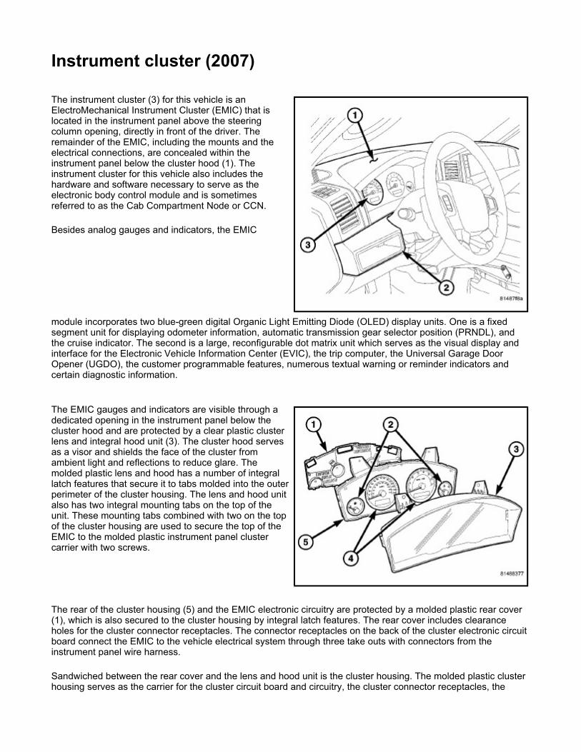
Instrument cluster (2007) The instrument cluster (3) for this vehicle is an ElectroMechanical Instrument Cluster (EMIC) that is located in the instrument panel above the steering column opening, directly in front of the driver. The remainder of the EMIC, including the mounts and the electrical connections, are concealed within the instrument panel below the cluster hood (1). The instrument cluster for this vehicle also includes the hardware and software necessary to serve as the electronic body control module and is sometimes referred to as the Cab Compartment Node or CCN.
Besides analog gauges and indicators, the EMIC
module incorporates two blue-green digital Organic Light Emitting Diode (OLED) display units. One is a fixed segment unit for displaying odometer information, automatic transmission gear selector position (PRNDL), and the cruise indicator. The second is a large, reconfigurable dot matrix unit which serves as the visual display and interface for the Electronic Vehicle Information Center (EVIC), the trip computer, the Universal Garage Door Opener (UGDO), the customer programmable features, numerous textual warning or reminder indicators and certain diagnostic information.
The EMIC gauges and indicators are visible through a dedicated opening in the instrument panel below the cluster hood and are protected by a clear plastic cluster lens and integral hood unit (3). The cluster hood serves as a visor and shields the face of the cluster from ambient light and reflections to reduce glare. The molded plastic lens and hood has a number of integral latch features that secure it to tabs molded into the outer perimeter of the cluster housing. The lens and hood unit also has two integral mounting tabs on the top of the unit. These mounting tabs combined with two on the top of the cluster housing are used to secure the top of the EMIC to the molded plastic instrument panel cluster carrier with two screws.
The rear of the cluster housing (5) and the EMIC electronic circuitry are protected by a molded plastic rear cover (1), which is also secured to the cluster housing by integral latch features. The rear cover includes clearance holes for the cluster connector receptacles. The connector receptacles on the back of the cluster electronic circuit board connect the EMIC to the vehicle electrical system through three take outs with connectors from the instrument panel wire harness.
Sandwiched between the rear cover and the lens and hood unit is the cluster housing. The molded plastic cluster housing serves as the carrier for the cluster circuit board and circuitry, the cluster connector receptacles, the

major (4) and minor (2) gauges, a Light Emitting Diode (LED) for each cluster indicator, the two OLED display units, an audible tone transducer, several LED units for general cluster illumination, the cluster overlay, and the gauge pointers. The cluster housing also has two integral mounting posts on its lower surface with rubber isolators used to secure the base of the EMIC to receptacles in the instrument panel cluster carrier.
The cluster overlay is a laminated plastic unit. The dark, visible, outer surface of the overlay is marked with all of the gauge dial faces and graduations, but this layer is also translucent. The darkness of this outer layer prevents the cluster from appearing cluttered or busy by concealing the cluster indicators that are not illuminated, while the translucence of this layer allows those indicators and icons that are illuminated to be readily visible. The underlying layer of the overlay is opaque and allows light from the LED for each of the various indicators and illumination lamps behind it to be visible through the outer layer of the overlay only through predetermined stencil-like cutouts. Rectangular openings in the overlay at the base of the speedometer and tachometer dial faces have smoked clear lenses through which the illuminated OLED display units can be viewed.
Several versions of the EMIC module are offered on this vehicle. These versions accommodate all of the variations of optional equipment and regulatory requirements for the various markets in which the vehicle is offered. The microprocessor-based EMIC utilizes integrated circuitry and information carried on the Controller Area Network (CAN) data bus along with several hard wired analog and multiplexed inputs to monitor sensors and switches throughout the vehicle. In response to those inputs, the internal circuitry and programming of the EMIC allow it to control and integrate many electronic functions and features of the vehicle through both hard wired outputs and the transmission of electronic message outputs to other electronic modules in the vehicle over the CAN data bus.
Besides typical instrument cluster gauge and indicator support, the electronic functions and features that the EMIC supports or controls include the following:
A/C Select and Evaporator Probe Support - The EMIC monitors A/C select switch and evaporator temperature sensor hard wired inputs from the Manual Temperature Control (MTC) control or electronic messages received over the CAN data bus from the Automatic Temperature Control (ATC) control, then transmits electronic A/C clutch request messages when appropriate to support the A/C clutch control feature.
Audible Warnings - The EMIC electronic circuit board is equipped with an audible tone transducer and programming that allows it to provide various audible alerts to the vehicle operator. These alerts include single chime tones and continuous slow or fast tones. An electromechanical relay is also soldered onto the circuit board to produce audible clicks that are used to emulate the sound of a conventional turn signal or hazard warning flasher.
Automatic Headlamps Support - On vehicles equipped with optional automatic headlamps, the EMIC calculates the average ambient light level based upon either a hard wired input from the sun load sensor on the top of the instrument panel or upon an electronic message received over the CAN data bus from the Rain Sensor Module (RSM) on the windshield below the automatic day/night inside rear view mirror mounting button, then transmits an electronic auto headlamps request message when appropriate to support the automatic headlamps feature.
Electric Backlight Status Support - On vehicles equipped with optional Automatic Temperature Control (ATC), the EMIC monitors electronic Electric BackLight (EBL) status messages received over the CAN data bus from the ATC control, then transmits electronic EBL status messages when appropriate to support the EBL feature.
Electronic Vehicle Information Center Support - In addition to the dot matrix Organic Light Emitting Diode (OLED) display, the EMIC provides support for each of the functions and features of the Electronic Vehicle Information Center (EVIC). This includes support for the compass, customer programmable features, textual warnings, Tire Pressure Monitor (TPM), trip computer, Universal Garage Door Opener (UGDO) and the upper instrument panel switch pod inputs that are used to control and configure many of the EVIC displays. This also includes display arbitrator programming, which controls the priorities, sequences, and transition of information that is displayed in the EVIC, particularly when multiple display requests are received simultaneously.
Enhanced Accident Response Support - The EMIC monitors an input from the Occupant Restraint Controller (ORC) and, following an airbag deployment, will immediately disable the power lock relay output, unlock all doors by activating the power unlock relay output, then enables the power lock relay output if the power lock switch input remains inactive for two seconds. The EMIC also monitors an input from the Powertrain Control Module (PCM) to automatically turn ON the interior lighting after an airbag deployment

event, 10 seconds after the vehicle speed is zero. The interior lighting remains illuminated until the ignition switch is turned to the OFF position, at which time the interior lighting returns to normal operation and control. These Enhanced Accident Response System (EARS) features are each dependent upon a functional vehicle electrical system following the vehicle impact event.
Fuel Level Data Support - The EMIC provides a current source for and receives a hard wired analog input from the fuel level sending unit located on the fuel pump module in the fuel tank. The EMIC uses this input to calculate the proper fuel gauge needle position and to control low fuel indicator operation. Based upon this input, the EMIC also uses electronic messaging to transmit this data over the CAN data bus for use by other electronic modules in the vehicle.
Heated Seat Switch Support and Switch Indicator Control - On vehicles equipped with optional heated seats, the EMIC monitors hard wired inputs from the heated seat switches in the lower instrument panel switch pod and transmits electronic heated seat request messages over the CAN data bus. This message wakes up the Heated Seat Module (HSM) when the switch is actuated. The EMIC then monitors electronic messages received over the CAN data bus from the HSM to control a high side driver output to the appropriate heated seat switch Light Emitting Diode (LED) indicators.
Ignition On and Ignition Accessory/On Relay Control - The EMIC monitors hard wired inputs from the ignition switch on the instrument panel, and provides low side driver outputs to control both the ignition ON and ignition ACCESSORY/ON relays in the Junction Block (JB) as appropriate.
Interior Lamp Load Shedding - The EMIC provides a battery saver feature which will automatically turn OFF all interior lamps if they remain ON after a timed interval of about eight minutes.
Interior Lighting Control - The EMIC monitors electronic messages and hard wired inputs from the interior lighting switch, the door ajar switches, the liftgate ajar switch, the liftgate flip-up glass ajar switch, the reading lamp switches, and the Sentry Key REmote Entry Module (SKREEM) (also known as the Wireless Control Module/WCM) to provide courtesy lamp control. This includes support for timed illuminated entry with theater-style fade-to-OFF and courtesy illumination DEFEAT features.
Panel Lamps Dimming Control - The EMIC monitors electronic dimming level messages received from the panel lamps dimmer switch input to the Steering Control Module (SCM) over the CAN data bus, then provides a hard wired 12-volt Pulse-Width Modulated (PWM) output that synchronizes the dimming level of all panel lamps dimmer controlled lamps with that of the cluster general illumination lighting.
Park Assist Switch Support and Switch Indicator Control - On vehicles equipped with the optional park assist system, the EMIC monitors a hard wired input from the park assist switch in the lower instrument panel switch pod and transmits electronic park assist switch status messages over the CAN data bus. This message tells the park assist module whether the system should be enabled or disabled when the switch is actuated. The EMIC then monitors electronic messages received over the CAN data bus from the park assist module to control a high side driver output to the park assist switch Light Emitting Diode (LED) disable indicator.
Power Lock System Control - The EMIC monitors inputs from the power lock switches and the Sentry Key REmote Entry Module (SKREEM) (also known as the Wireless Control Module/WCM) to provide control of the power lock motors through high side driver outputs to the door lock and unlock relays. This includes support for rolling door locks (also known as automatic door locks), automatic door unlock, and a door lock inhibit mode.
Remote Keyless Entry Support - The EMIC supports the Remote Keyless Entry (RKE) system features, including support for the RKE LOCK, UNLOCK (with optional driver-door-only unlock, and unlock-all-doors), PANIC, audible chirp, optical chirp, illuminated entry modes, an RKE programming mode, as well as optional Vehicle Theft Security System (VTSS) arming (when the proper VTSS arming conditions are met) and disarming.
Vehicle Theft Security System Control - The EMIC monitors inputs from the door ajar switches, the Steering Control Module (SCM), the Sentry Key REmote Entry Module (SKREEM) (also known as the Wireless Control Module/WCM) and, on vehicles so equipped, the intrusion module then provides electronic horn and lighting request messages to the Front Control Module (FCM) located on the Integrated Power Module (IPM) for the appropriate VTSS alarm output features.

Except With Diesel Engine Or Rear Fog Lamps
With Diesel Engine Or Rear Fog Lamps

The EMIC houses 4 analog gauges and has provisions for up to 18 indicators. Some of the EMIC indicators are automatically configured when the EMIC is connected to the vehicle electrical system for compatibility with certain optional equipment or equipment required for regulatory purposes in certain markets. While each EMIC may have provisions for indicators to support every available option, the configurable indicators will not be functional in a vehicle that does not have the equipment that an indicator supports.
The EMIC includes the following analog gauges:
Engine Temperature Gauge (18) Fuel Gauge (28) Speedometer (6) Tachometer (13)
The EMIC includes the following OLED display units:
Dot Matrix Display (19) - Electronic Vehicle Information Center (EVIC), Trip Odometer A and B, and Textual Messages
Fixed Segment Display - Includes Gear Selector Indicator (27), Odometer (26) and Cruise Indicator (25)
The EMIC includes provisions for the following indicators:
Adjustable Pedal System Indicator - textual messages in dot matrix display (19) Airbag Indicator (24) Ajar Indicators - textual messages and icon in dot matrix display (19) for doors, hood, liftgate and liftgate
flip-up glass Antilock Brake System (ABS) Indicator (12) Brake Indicator (11) Charging Indicator (3) Check Gas Cap Indicator - textual message in dot matrix display (19) Check Gauges Indicator - textual message in dot matrix display (19) Check Shift Procedure Indicator - textual message in dot matrix display (19) Coolant Low Indicator - textual message and icon in dot matrix display (19) Cruise Indicator (25) - text in fixed segment display Electronic Stability Program (ESP)/Brake Assist System (BAS) Indicator (22) - and textual messages
w/SRT8
in dot matrix display (19) Electronic Throttle Control (ETC) Indicator (17) Four-Wheel Drive Low Indicator (23) Four-Wheel Drive System In Neutral Indicator - textual message and icon in dot matrix display (19) Front Fog Lamp Indicator (2) Gear Selector Indicator (27) High Beam Indicator (9) Low Brake Fluid Level Indicator - textual message in dot matrix display (19) Low Fuel Indicator (1) Low Oil Pressure Indicator (15) Malfunction Indicator Lamp (MIL) (10) Memory System Indicator - textual messages in dot matrix display (19) Oil Pressure Indicator (SRT8 only) - textual message and icon in dot matrix display (19) Oil Temperature Indicator (SRT8 only) - textual message and icon in dot matrix display (19) Park Assist Disabled Indicator - textual message in dot matrix display (19) Perform Service Indicator - textual message in dot matrix display (19) Rear Fog Lamp Indicator (5) - in markets where rear fog lamps are available only Seat Belt Indicator (7) Security Indicator (14) - also textual messages for Sentry Key Immobilizer System (SKIS) in dot matrix
display (19) Service Column Lock Indicator - textual message in dot matrix display (19) Service Exhaust Indicator - textual message in dot matrix display (19) with diesel only Service Four-Wheel Drive System Indicator - textual message in dot matrix display (19) Service Park Assist System Indicator - textual message in dot matrix display (19) SmartBeam® (Auto High Beam) Indicator - textual messages in dot matrix display (19) Tire Pressure Monitor (TPM) Indicator (4) - may also include textual messages in dot matrix display (19) Tow/Haul Indicator (20) Traction Control/Electronic Stability Program (ESP) Indicator (16) Transmission Overtemp Indicator - textual message in dot matrix display (19) Turn-Signal-On Reminder Indicator - textual message and icon in dot matrix display (19) Turn Signal (Right and Left) Indicators (8) Upshift Indicator (SRT8 only) - textual message and icon in dot matrix display (19) Wait-To-Start Indicator (21) - with diesel only Washer Fluid Indicator - textual message and icon in dot matrix display (19) Water-In-Fuel Indicator - textual message in dot matrix display (19) with diesel only
Each indicator in the EMIC, except those located within an OLED display unit, is illuminated by a dedicated LED that is soldered onto the EMIC electronic circuit board. Cluster illumination is accomplished by several dimmable LED units, which illuminate each of the gauge dial faces for visibility when the exterior lighting is turned ON. These LED units are not available for service replacement and, if damaged or ineffective, the entire EMIC must be replaced.
Hard wired circuitry connects the EMIC to the electrical system of the vehicle. These hard wired circuits are integral to several wire harnesses, which are routed throughout the vehicle and retained by many different methods. These circuits may be connected to each other, to the vehicle electrical system and to the EMIC through the use of a combination of soldered splices, splice block connectors, and many different types of wire harness terminal connectors and insulators. Refer to the appropriate wiring information. The wiring information includes wiring diagrams, proper wire and connector repair procedures, further details on wire harness routing and retention, as well as pin-out and location views for the various wire harness connectors, splices and grounds.
The EMIC module for this vehicle is serviced only as a complete unit. The EMIC module cannot be adjusted or repaired. If a gauge, an LED unit, an OLED display unit, the electronic circuit board, the circuit board hardware, the cluster overlay, or the EMIC housing are damaged or ineffective, the entire EMIC module must be replaced. The cluster lens, hood and mask unit is available for separate service replacement.

Instrument cluster (2008) The instrument cluster (3) for this vehicle includes the hardware and software necessary to serve as the electronic body control module and is also referred to as the Cab Compartment Node (CCN) The instrument cluster is located in the instrument panel above the steering column opening, directly in front of the driver. The remainder of the CCN, including the mounts and the electrical connections, are concealed within the instrument panel below the cluster hood (1).
Besides analog gauges and indicators, the CCN module incorporates two white digital Organic Light Emitting Diode (OLED) display units. One is a fixed segment unit for displaying odometer information, automatic transmission gear selector position (PRNDL), and the cruise indicator. The second is a large, reconfigurable dot matrix unit which serves as the visual display and interface for the Electronic Vehicle Information Center (EVIC), the trip computer, the Universal Garage Door Opener (UGDO), the customer programmable features, numerous textual warning or reminder indicators and certain diagnostic information.
The CCN gauges and indicators are visible through a dedicated opening in the instrument panel below the cluster hood and are protected by a clear plastic cluster lens and integral hood unit (3). The cluster hood serves as a visor and shields the face of the cluster from ambient light and reflections to reduce glare. The molded plastic lens and hood has a number of integral latch features that secure it to tabs molded into the outer perimeter of the cluster housing. The lens and hood unit also has two integral mounting tabs on the top of the unit. These mounting tabs combined with two on the top of the cluster housing are used to secure the top of the EMIC to the molded plastic instrument panel cluster carrier with two screws.
The rear of the cluster housing (5) and the CCN electronic circuitry are protected by a molded plastic rear cover (1), which is also secured to the cluster housing by integral latch features. The rear cover includes clearance holes for the cluster connector receptacles. The connector receptacles on the back of the cluster electronic circuit board connect the CCN to the vehicle electrical system through two take outs with connectors from the instrument panel wire harness.
Sandwiched between the rear cover and the lens and hood unit is the cluster housing. The molded plastic cluster housing serves as the carrier for the cluster circuit board and circuitry, the cluster connector receptacles, the major (4) and minor (2) gauges, a Light Emitting Diode (LED) for each cluster indicator, the two OLED display units, an audible tone transducer, several LED units for general cluster illumination, the cluster overlay, and the gauge pointers. The cluster housing also has two integral mounting posts on its lower surface with rubber isolators used to secure the base of the CCN to receptacles in the instrument panel cluster carrier.

The cluster overlay is a laminated plastic unit. On Laredo vehicles, the dark, visible, outer surface of the overlay is marked with all of the gauge dial faces and graduations, but this layer is also translucent. On Limited, Overland and SRT8 vehicles, the argent silver outer surface of the overlay appears unmarked. The darkness of this outer layer prevents the cluster from appearing cluttered or busy by concealing the cluster indicators (and the gauges on Limited, Overland and SRT8 vehicles) that are not illuminated, while the translucence of this layer allows those items that are illuminated to be readily visible. The underlying layer of the overlay is opaque and allows light from the LED for each of the various indicators and illumination lamps behind it to be visible through the outer layer of the overlay only through predetermined stencil-like cutouts. Rectangular openings in the overlay at the base of the speedometer and tachometer dial faces have smoked clear lenses through which the illuminated OLED display units can be viewed.
Several versions of the CCN module are offered on this vehicle. These versions accommodate all of the variations of optional equipment and regulatory requirements for the various markets in which the vehicle is offered. The microprocessor-based CCN utilizes integrated circuitry and information carried on the Controller Area Network (CAN) data bus and the Local Interface Network (LIN) data bus along with several hardwired analog and multiplexed inputs to monitor sensors and switches throughout the vehicle. In response to those inputs, the internal circuitry and programming of the CCN allow it to control and integrate many electronic functions and features of the vehicle through both hard wired outputs and the transmission of electronic message outputs to other electronic modules in the vehicle over the CAN and LIN data busses.
Besides typical instrument cluster gauge and indicator support, the electronic functions and features that the CCN supports or controls include the following:
A/C Select and Evaporator Probe Support - The CCN monitors A/C select switch and evaporator temperature sensor hardwired inputs from the Manual Temperature Control (MTC) control or electronic messages received over the CAN data bus from the Automatic Temperature Control (ATC) control, then transmits electronic A/C clutch request messages when appropriate to support the A/C clutch control feature.
Audible Warnings - The CCN electronic circuit board is equipped with an audible tone transducer and programming that allows it to provide various audible alerts to the vehicle operator. These alerts include single chime tones and continuous slow or fast tones. An electromechanical relay is also soldered onto the circuit board to produce audible clicks that are used to emulate the sound of a conventional turn signal or hazard warning flasher.
Automatic Headlamps Support - On vehicles equipped with optional automatic headlamps, the EMIC calculates the average ambient light level based upon an electronic message received over the CAN data bus from the Rain Sensor Module (RSM) on the windshield below the automatic day/night inside rear view mirror mounting button, then transmits an electronic auto headlamps request message when appropriate to support the automatic headlamps feature.
Electric Backlight Status Support - On vehicles equipped with optional Automatic Temperature Control (ATC), the CCN monitors electronic Electric BackLight (EBL) status messages received over the CAN data bus from the ATC control, then transmits electronic EBL status messages when appropriate to support the EBL feature.
Electronic Vehicle Information Center Support - In addition to the dot matrix Organic Light Emitting Diode (OLED) display, the CCN provides support for each of the functions and features of the Electronic Vehicle Information Center (EVIC). This includes support for the compass, thermometer, audio system mode, customer programmable features, textual warnings, premium Tire Pressure Monitor (TPM), trip computer, U-Connect™ Hands-Free communication, HomeLink™ Universal Garage Door Opener (UGDO) and the steering wheel switch electronic message inputs received over the Local Interface Network (LIN) data bus that are used to control and configure many of the EVIC displays. This also includes display arbitrator programming, which controls the priorities, sequences, and transition of information that is displayed in the EVIC, particularly when multiple display requests are received simultaneously.
Enhanced Accident Response Support - The CCN monitors an input from the Occupant Restraint Controller (ORC) and, following an airbag deployment, will immediately disable the power lock output, unlock all doors by activating the power unlock output, then enables the power lock output if the power lock switch input remains inactive for two seconds. The CCN also monitors an input from the Powertrain Control Module (PCM) to automatically turn ON the interior lighting after an airbag deployment event, 10 seconds after the vehicle speed is zero. The interior lighting remains illuminated until the ignition switch is turned to the OFF position, at which time the interior lighting returns to normal operation and control. These Enhanced Accident Response System (EARS) features are each dependent upon a functional vehicle

electrical system following the vehicle impact event. Exterior Lighting Switch Support - The CCN monitors electronic exterior lighting switch, and turn
signal switch status messages from the Steering Control Module (SCM) on the steering column over the LIN data bus and transmits the appropriate electronic exterior lighting and turn signal request messages to the Front Control Module (FCM) located on the Integrated Power Module (IPM) over the CAN data bus to support the exterior lighting functions.
Fuel Level Data Support - The CCN provides a current source for and receives a hard wired analog input from the fuel level sending unit located on the fuel pump module in the fuel tank. The CCN uses this input to calculate the proper fuel gauge needle position and to control low fuel indicator operation. Based upon this input, the CCN also uses electronic messaging to transmit this data over the CAN data bus for use by other electronic modules in the vehicle.
Heated Seat Switch Support and Switch Indicator Control - On vehicles equipped with optional heated seats, the CCN monitors electronic heated seat switch status messages from the front heated seat switches in the instrument panel switch pod and hard wired inputs from the rear heated seat switches and transmits electronic heated seat request messages over the CAN data bus. This message wakes up the Heated Seat Module (HSM) when the switch is actuated. The CCN then monitors electronic messages received over the CAN data bus from the HSM to send electronic status messages over the LIN data bus back to the lower switch pod to control front heated seat switch Light Emitting Diode (LED) indicators and uses a high side driver output to control the appropriate rear heated seat switch LED indicators.
Hill Descent Switch Support and Switch Indicator Control - On vehicles equipped with the optional hill descent system, the CCN monitors electronic hill descent switch status messages from the hill descent switch in the instrument panel switch pod over the LIN data bus and transmits electronic hill descent switch request messages to the Controller Anti-lock Brake (CAB) over the CAN data bus. This message tells the CAB whether the system should be enabled or disabled when the switch is actuated. The CCN then monitors electronic messages received over the CAN data bus from the CAB and transmits electronic messages to the instrument panel switch pod over the LIN data bus to control the hill descent switch Light Emitting Diode (LED) disable indicator.
Ignition On and Ignition Accessory/On Relay Control - The CCN monitors electronic ignition switch status messages received over the CAN bus from the Wireless Ignition Node (WIN) and a hardwired input from the ignition switch on the instrument panel, and provides low side driver outputs to control both the ignition ON and ignition ACCESSORY/ON relays in the Junction Block (JB) as appropriate.
Interior Lamp Load Shedding - The CCN provides a battery saver feature which will automatically turn OFF all interior lamps if they remain ON after a timed interval of about eight minutes.
Interior Lighting Control - The CCN monitors electronic messages and hard wired inputs from the interior lighting switch, the door ajar switches, the liftgate ajar switch, the liftgate flip-up glass ajar switch, the reading lamp switches and the WIN to provide courtesy lamp control. This includes support for timed illuminated entry with theater-style fade-to-OFF and courtesy illumination DEFEAT features.
Local Interface Network Master Module - The CCN is the master module for the LIN data bus. In this role it gathers information from the compass sensor, the Heated Seat Module (HSM), the instrument panel switch pods, the steering wheel switches and the SCM, then either acts on that information directly or places electronic messages on the CAN data bus for use by other modules
Panel Lamps Dimming Control - The CCN monitors electronic dimming level messages received from the panel lamps dimmer switch input to the SCM over the LIN data bus, then provides both a hard wired 12-volt Pulse-Width Modulated (PWM) output and electronic message outputs over the LIN data bus that synchronizes the dimming level of all panel lamps dimmer controlled lamps with that of the cluster general illumination lighting.
Park Assist Switch Support and Switch Indicator Control - On vehicles equipped with the optional park assist system, the CCN monitors electronic park assist switch status messages from the park assist switch in the instrument panel switch pod over the LIN data bus and transmits electronic park assist switch request messages to the park assist module over the CAN data bus. This message tells the park assist module whether the system should be enabled or disabled when the switch is actuated. The CCN then monitors electronic messages received over the CAN data bus from the park assist module and transmits electronic messages to the instrument panel switch pod over the LIN data bus to control the park assist switch Light Emitting Diode (LED) disable indicator.
Power Inverter Support - The CCN monitors a hardwired input from the power inverter to determine the inverter status, then transmits electronic inverter status messages to other electronic modules in the vehicle over the CAN data bus.
Power Lock System Control - The CCN monitors inputs from the power lock switches and the WIN to provide control of the power lock motors through high side and low side driver outputs. This includes support for rolling door locks (also known as automatic door locks), automatic door unlock, and a door lock inhibit mode.
Remote Keyless Entry Support - The CCN supports the Remote Keyless Entry (RKE) system features, including support for the RKE LOCK, UNLOCK (with optional driver-door-only unlock, and unlock-all-doors), PANIC, audible chirp, optical chirp, illuminated entry modes, an RKE programming mode, as well as optional Vehicle Theft Security System (VTSS) arming (when the proper VTSS arming conditions are met) and disarming.
Remote Radio Switch Support - The CCN receives electronic message inputs from the remote radio switches on the steering wheel over the LIN data bus, then provides electronic radio request messages over the CAN data bus to support the remote radio switch function.
Remote Start System Support - The CCN receives electronic message inputs from the WIN and then displays the appropriate remote start system textual reminder messages to the vehicle operator within the CCN dot matrix display.
Steering Wheel Switch Support - The CCN receives electronic message inputs from the steering wheel switches on the steering wheel over the LIN data bus to control and configure many of the EVIC displays and functions.
Vehicle Theft Security System Control - The CCN monitors inputs from the door ajar switches, and the WIN, on vehicles so equipped. The intrusion module then provides electronic horn and lighting request messages to the Front Control Module (FCM) located on the Integrated Power Module (IPM) for the appropriate VTSS alarm output features.
Wiper and Washer Switch Support - The CCN monitors electronic wiper switch and washer switch status messages from the SCM on the steering column over the LIN data bus and transmits the appropriate electronic wiper and washer request messages to the FCM located on the IPM over the CAN data bus to support the wiper and washer system functions, including the headlamps-on with wipers programmable feature.
Except With Diesel Engine Or Rear Fog Lamps

The CCN houses 4 analog gauges and has provisions for up to 19 indicators. Some of the CCN indicators are automatically configured when the CCN is connected to the vehicle electrical system for compatibility with certain optional equipment or equipment required for regulatory purposes in certain markets. While each CCN may have provisions for indicators to support every available option, the configurable indicators will not be functional in a vehicle that does not have the equipment that an indicator supports.
The CCN includes the following analog gauges:
Engine Temperature Gauge (18)
With Diesel Engine Or Rear Fog Lamps
w/SRT8

Fuel Gauge (28) Speedometer (6) Tachometer (13)
The CCN includes the following OLED display units:
Dot Matrix Display (19) - Electronic Vehicle Information Center (EVIC), Trip Odometer A and B, and Textual Messages
Fixed Segment Display - Includes Gear Selector Indicator (27), Odometer (26) and Cruise Indicator (25)
The CCN includes provisions for the following indicators:
Adjustable Pedal System Indicator - textual messages in dot matrix display (19) Airbag Indicator (24) Ajar Indicators - textual messages and icon in dot matrix display (19) for doors, hood, liftgate and liftgate
flip-up glass Antilock Brake System (ABS) Indicator (12) Brake Indicator (11) Change Oil Indicator - textual message in dot matrix display (19) on domestic market vehicles only Charging Indicator (3) Check Gauges Indicator - textual message in dot matrix display (19) Check Shift Procedure Indicator - textual message in dot matrix display (19) Coolant Low Indicator - textual message and icon in dot matrix display (19) Cruise Indicator (25) - text in fixed segment display Electronic Stability Program (ESP)/Brake Assist System (BAS) Indicator (22) - and textual messages
in dot matrix display (19) Electronic Throttle Control (ETC) Indicator (17) Four-Wheel Drive Low Indicator (23) Four-Wheel Drive System In Neutral Indicator - textual message and icon in dot matrix display (19) Front Fog Lamp Indicator (2) Gas Cap Indicator - textual message in dot matrix display (19) Gear Selector Indicator (27) High Beam Indicator (9) Hill Descent Indicator - textual message in dot matrix display (19) Low Brake Fluid Level Indicator - textual message in dot matrix display (19) Low Fuel Indicator (1) - or within the fuel gauge (28) dial face on Limited and Overland vehicles
manufactured for certain export markets. Low Oil Pressure Indicator (15) Malfunction Indicator Lamp (MIL) (10) Memory System Indicator - textual messages in dot matrix display (19) No Bus Indicator - textual message in dot matrix display (19) No Fuse Indicator - textual message in dot matrix display (19) Oil Pressure Indicator (SRT8 only) - textual message and icon in dot matrix display (19) Oil Temperature Indicator (SRT8 only) - textual message and icon in dot matrix display (19) Park Assist Disabled Indicator - textual message in dot matrix display (19) Perform Service Indicator - textual message in dot matrix display (19) with diesel only Position Lamp Indicator (1) - on Limited and Overland vehicles manufactured for certain export markets. Power Liftgate Indicator - textual messages in dot matrix display (19) Rear Fog Lamp Indicator (5) - in markets where rear fog lamps are available only Remote Start Indicator - textual messages in dot matrix display (19) Seat Belt Indicator (7) Security Indicator (14) - also textual messages for Sentry Key Immobilizer System (SKIS) in dot matrix
display (19) Service Column Lock Indicator - textual message in dot matrix display (19) Service Exhaust Indicator - textual message in dot matrix display (19) with diesel only Service Four-Wheel Drive System Indicator - textual message in dot matrix display (19) Service Park Assist System Indicator - textual message in dot matrix display (19) SmartBeam® (Auto High Beam) Indicator - textual messages in dot matrix display (19) Tire Pressure Monitor (TPM) Indicator (4) - may also include textual messages in dot matrix display (19) Tow/Haul Indicator (20)

Traction Control/Electronic Stability Program (ESP) Indicator (16) Transmission Overtemp Indicator - textual message in dot matrix display (19) Turn-Signal-On Reminder Indicator - textual message and icon in dot matrix display (19) Turn Signal (Right and Left) Indicators (8) Upshift Indicator (SRT8 only) - textual message and icon in dot matrix display (19) Wait-To-Start Indicator (21) - with diesel only Washer Fluid Indicator - textual message and icon in dot matrix display (19) Water-In-Fuel Indicator - textual message in dot matrix display (19) with diesel only
Each indicator in the instrument cluster, except those located within an OLED display unit, is illuminated by a dedicated LED that is soldered onto the CCN electronic circuit board. Cluster illumination is accomplished by several dimmable LED units, which illuminate each of the Laredo gauge dial faces for visibility whenever the exterior lighting is turned ON, or the Limited and Overland gauge dial faces whenever the ignition is turned ON. These LED units are not available for service replacement and, if damaged or ineffective, the entire unit must be replaced.
Hard wired circuitry connects the CCN to the electrical system of the vehicle. These hard wired circuits are integral to several wire harnesses, which are routed throughout the vehicle and retained by many different methods. These circuits may be connected to each other, to the vehicle electrical system and to the CCN through the use of a combination of soldered splices, splice block connectors, and many different types of wire harness terminal connectors and insulators. Refer to the appropriate wiring information. The wiring information includes wiring diagrams, proper wire and connector repair procedures, further details on wire harness routing and retention, as well as pin-out and location views for the various wire harness connectors, splices and grounds.
The CCN module for this vehicle is serviced only as a complete unit. The CCN module cannot be adjusted or repaired. If a gauge, an LED unit, an OLED display unit, the electronic circuit board, the circuit board hardware, the cluster overlay, or the cluster housing are damaged or ineffective, the entire CCN module must be replaced. The cluster lens, hood and mask unit is available for separate service replacement.
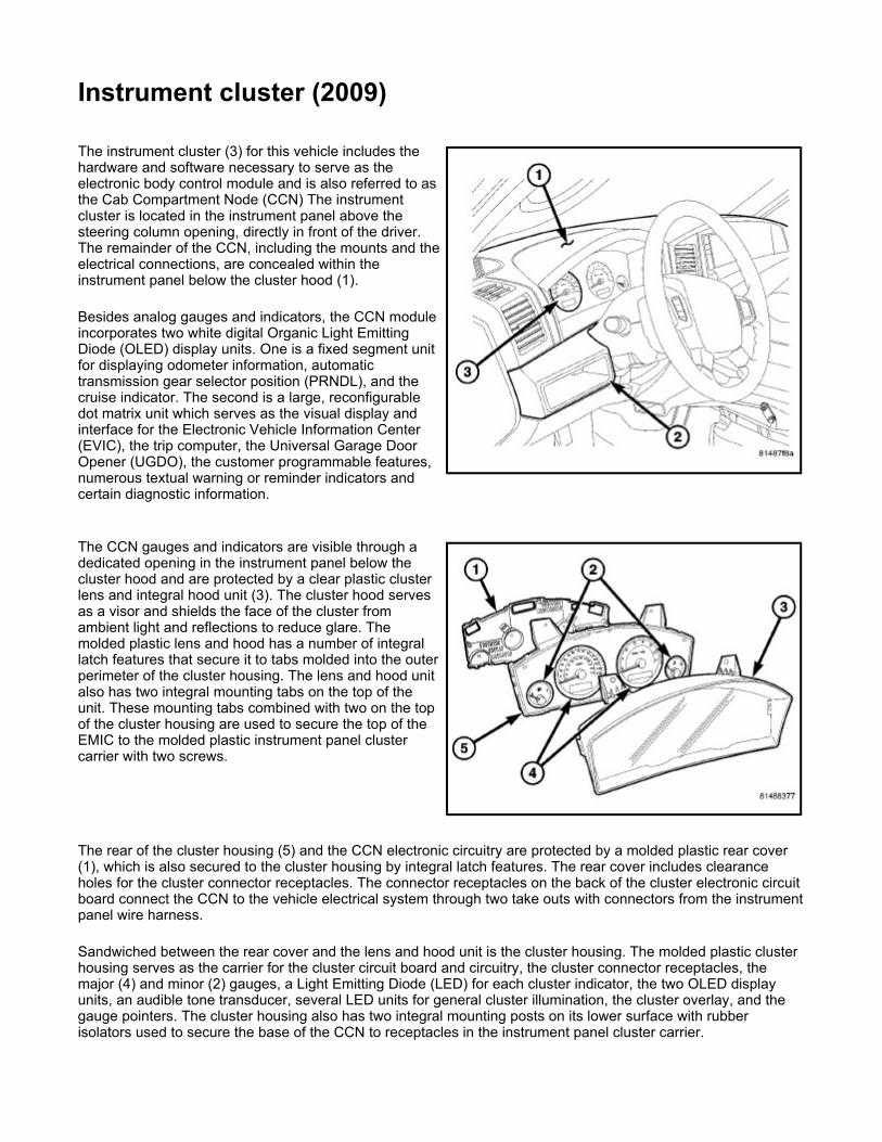
Instrument cluster (2009) The instrument cluster (3) for this vehicle includes the hardware and software necessary to serve as the electronic body control module and is also referred to as the Cab Compartment Node (CCN) The instrument cluster is located in the instrument panel above the steering column opening, directly in front of the driver. The remainder of the CCN, including the mounts and the electrical connections, are concealed within the instrument panel below the cluster hood (1).
Besides analog gauges and indicators, the CCN module incorporates two white digital Organic Light Emitting Diode (OLED) display units. One is a fixed segment unit for displaying odometer information, automatic transmission gear selector position (PRNDL), and the cruise indicator. The second is a large, reconfigurable dot matrix unit which serves as the visual display and interface for the Electronic Vehicle Information Center (EVIC), the trip computer, the Universal Garage Door Opener (UGDO), the customer programmable features, numerous textual warning or reminder indicators and certain diagnostic information.
The CCN gauges and indicators are visible through a dedicated opening in the instrument panel below the cluster hood and are protected by a clear plastic cluster lens and integral hood unit (3). The cluster hood serves as a visor and shields the face of the cluster from ambient light and reflections to reduce glare. The molded plastic lens and hood has a number of integral latch features that secure it to tabs molded into the outer perimeter of the cluster housing. The lens and hood unit also has two integral mounting tabs on the top of the unit. These mounting tabs combined with two on the top of the cluster housing are used to secure the top of the EMIC to the molded plastic instrument panel cluster carrier with two screws.
The rear of the cluster housing (5) and the CCN electronic circuitry are protected by a molded plastic rear cover (1), which is also secured to the cluster housing by integral latch features. The rear cover includes clearance holes for the cluster connector receptacles. The connector receptacles on the back of the cluster electronic circuit board connect the CCN to the vehicle electrical system through two take outs with connectors from the instrument panel wire harness.
Sandwiched between the rear cover and the lens and hood unit is the cluster housing. The molded plastic cluster housing serves as the carrier for the cluster circuit board and circuitry, the cluster connector receptacles, the major (4) and minor (2) gauges, a Light Emitting Diode (LED) for each cluster indicator, the two OLED display units, an audible tone transducer, several LED units for general cluster illumination, the cluster overlay, and the gauge pointers. The cluster housing also has two integral mounting posts on its lower surface with rubber isolators used to secure the base of the CCN to receptacles in the instrument panel cluster carrier.

The cluster overlay is a laminated plastic unit. On Laredo vehicles, the dark, visible, outer surface of the overlay is marked with all of the gauge dial faces and graduations, but this layer is also translucent. On Limited, Overland and SRT8 vehicles, the argent silver outer surface of the overlay appears unmarked. The darkness of this outer layer prevents the cluster from appearing cluttered or busy by concealing the cluster indicators (and the gauges on Limited, Overland and SRT8 vehicles) that are not illuminated, while the translucence of this layer allows those items that are illuminated to be readily visible. The underlying layer of the overlay is opaque and allows light from the LED for each of the various indicators and illumination lamps behind it to be visible through the outer layer of the overlay only through predetermined stencil-like cutouts. Rectangular openings in the overlay at the base of the speedometer and tachometer dial faces have smoked clear lenses through which the illuminated OLED display units can be viewed.
Several versions of the CCN module are offered on this vehicle. These versions accommodate all of the variations of optional equipment and regulatory requirements for the various markets in which the vehicle is offered. The microprocessor-based CCN utilizes integrated circuitry and information carried on the Controller Area Network (CAN) data bus and the Local Interface Network (LIN) data bus along with several hardwired analog and multiplexed inputs to monitor sensors and switches throughout the vehicle. In response to those inputs, the internal circuitry and programming of the CCN allow it to control and integrate many electronic functions and features of the vehicle through both hard wired outputs and the transmission of electronic message outputs to other electronic modules in the vehicle over the CAN and LIN data busses.
Besides typical instrument cluster gauge and indicator support, the electronic functions and features that the CCN supports or controls include the following:
A/C Select and Evaporator Probe Support - The CCN monitors A/C select switch and evaporator temperature sensor hardwired inputs from the Manual Temperature Control (MTC) control or electronic messages received over the CAN data bus from the Automatic Temperature Control (ATC) control, then transmits electronic A/C clutch request messages when appropriate to support the A/C clutch control feature.
Audible Warnings - The CCN electronic circuit board is equipped with an audible tone transducer and programming that allows it to provide various audible alerts to the vehicle operator. These alerts include single chime tones and continuous slow or fast tones. An electromechanical relay is also soldered onto the circuit board to produce audible clicks that are used to emulate the sound of a conventional turn signal or hazard warning flasher.
Automatic Headlamps Support - On vehicles equipped with optional automatic headlamps, the EMIC calculates the average ambient light level based upon an electronic message received over the CAN data bus from the Rain Sensor Module (RSM) on the windshield below the automatic day/night inside rear view mirror mounting button, then transmits an electronic auto headlamps request message when appropriate to support the automatic headlamps feature.
Electric Backlight Status Support - On vehicles equipped with optional Automatic Temperature Control (ATC), the CCN monitors electronic Electric BackLight (EBL) status messages received over the CAN data bus from the ATC control, then transmits electronic EBL status messages when appropriate to support the EBL feature.
Electronic Vehicle Information Center Support - In addition to the dot matrix Organic Light Emitting Diode (OLED) display, the CCN provides support for each of the functions and features of the Electronic Vehicle Information Center (EVIC). This includes support for the compass, thermometer, audio system mode, customer programmable features, textual warnings, premium Tire Pressure Monitor (TPM), trip computer, U-Connect™ Hands-Free communication, HomeLink™ Universal Garage Door Opener (UGDO) and the steering wheel switch electronic message inputs received over the Local Interface Network (LIN) data bus that are used to control and configure many of the EVIC displays. This also includes display arbitrator programming, which controls the priorities, sequences, and transition of information that is displayed in the EVIC, particularly when multiple display requests are received simultaneously.
Enhanced Accident Response Support - The CCN monitors an input from the Occupant Restraint Controller (ORC) and, following an airbag deployment, will immediately disable the power lock output, unlock all doors by activating the power unlock output, then enables the power lock output if the power lock switch input remains inactive for two seconds. The CCN also monitors an input from the Powertrain Control Module (PCM) to automatically turn ON the interior lighting after an airbag deployment event, 10 seconds after the vehicle speed is zero. The interior lighting remains illuminated until the ignition switch is turned to the OFF position, at which time the interior lighting returns to normal operation and control. These Enhanced Accident Response System (EARS) features are each dependent upon a functional vehicle

electrical system following the vehicle impact event. Exterior Lighting Switch Support - The CCN monitors electronic exterior lighting switch, and turn
signal switch status messages from the Steering Control Module (SCM) on the steering column over the LIN data bus and transmits the appropriate electronic exterior lighting and turn signal request messages to the Front Control Module (FCM) located on the Integrated Power Module (IPM) over the CAN data bus to support the exterior lighting functions.
Fuel Level Data Support - The CCN provides a current source for and receives a hard wired analog input from the fuel level sending unit located on the fuel pump module in the fuel tank. The CCN uses this input to calculate the proper fuel gauge needle position and to control low fuel indicator operation. Based upon this input, the CCN also uses electronic messaging to transmit this data over the CAN data bus for use by other electronic modules in the vehicle.
Heated Seat Switch Support and Switch Indicator Control - On vehicles equipped with optional heated seats, the CCN monitors electronic heated seat switch status messages from the front heated seat switches in the instrument panel switch pod and hard wired inputs from the rear heated seat switches and transmits electronic heated seat request messages over the CAN data bus. This message wakes up the Heated Seat Module (HSM) when the switch is actuated. The CCN then monitors electronic messages received over the CAN data bus from the HSM to send electronic status messages over the LIN data bus back to the lower switch pod to control front heated seat switch Light Emitting Diode (LED) indicators and uses a high side driver output to control the appropriate rear heated seat switch LED indicators.
Hill Descent Switch Support and Switch Indicator Control - On vehicles equipped with the optional hill descent system, the CCN monitors electronic hill descent switch status messages from the hill descent switch in the instrument panel switch pod over the LIN data bus and transmits electronic hill descent switch request messages to the Controller Anti-lock Brake (CAB) over the CAN data bus. This message tells the CAB whether the system should be enabled or disabled when the switch is actuated. The CCN then monitors electronic messages received over the CAN data bus from the CAB and transmits electronic messages to the instrument panel switch pod over the LIN data bus to control the hill descent switch Light Emitting Diode (LED) disable indicator.
Ignition On and Ignition Accessory/On Relay Control - The CCN monitors electronic ignition switch status messages received over the CAN bus from the Wireless Ignition Node (WIN) and a hardwired input from the ignition switch on the instrument panel, and provides low side driver outputs to control both the ignition ON and ignition ACCESSORY/ON relays in the Junction Block (JB) as appropriate.
Interior Lamp Load Shedding - The CCN provides a battery saver feature which will automatically turn OFF all interior lamps if they remain ON after a timed interval of about eight minutes.
Interior Lighting Control - The CCN monitors electronic messages and hard wired inputs from the interior lighting switch, the door ajar switches, the liftgate ajar switch, the liftgate flip-up glass ajar switch, the reading lamp switches and the WIN to provide courtesy lamp control. This includes support for timed illuminated entry with theater-style fade-to-OFF and courtesy illumination DEFEAT features.
Local Interface Network Master Module - The CCN is the master module for the LIN data bus. In this role it gathers information from the compass sensor, the Heated Seat Module (HSM), the instrument panel switch pods, the steering wheel switches and the SCM, then either acts on that information directly or places electronic messages on the CAN data bus for use by other modules
Panel Lamps Dimming Control - The CCN monitors electronic dimming level messages received from the panel lamps dimmer switch input to the SCM over the LIN data bus, then provides both a hard wired 12-volt Pulse-Width Modulated (PWM) output and electronic message outputs over the LIN data bus that synchronizes the dimming level of all panel lamps dimmer controlled lamps with that of the cluster general illumination lighting.
Park Assist Switch Support and Switch Indicator Control - On vehicles equipped with the optional park assist system, the CCN monitors electronic park assist switch status messages from the park assist switch in the instrument panel switch pod over the LIN data bus and transmits electronic park assist switch request messages to the park assist module over the CAN data bus. This message tells the park assist module whether the system should be enabled or disabled when the switch is actuated. The CCN then monitors electronic messages received over the CAN data bus from the park assist module and transmits electronic messages to the instrument panel switch pod over the LIN data bus to control the park assist switch Light Emitting Diode (LED) disable indicator.
Power Inverter Support - The CCN monitors a hardwired input from the power inverter to determine the inverter status, then transmits electronic inverter status messages to other electronic modules in the vehicle over the CAN data bus.
Power Lock System Control - The CCN monitors inputs from the power lock switches and the WIN to provide control of the power lock motors through high side and low side driver outputs. This includes support for rolling door locks (also known as automatic door locks), automatic door unlock, and a door lock inhibit mode.

Remote Keyless Entry Support - The CCN supports the Remote Keyless Entry (RKE) system features, including support for the RKE LOCK, UNLOCK (with optional driver-door-only unlock, and unlock-all-doors), PANIC, audible chirp, optical chirp, illuminated entry modes, an RKE programming mode, as well as optional Vehicle Theft Security System (VTSS) arming (when the proper VTSS arming conditions are met) and disarming.
Remote Radio Switch Support - The CCN receives electronic message inputs from the remote radio switches on the steering wheel over the LIN data bus, then provides electronic radio request messages over the CAN data bus to support the remote radio switch function.
Remote Start System Support - The CCN receives electronic message inputs from the WIN and then displays the appropriate remote start system textual reminder messages to the vehicle operator within the CCN dot matrix display.
Steering Wheel Switch Support - The CCN receives electronic message inputs from the steering wheel switches on the steering wheel over the LIN data bus to control and configure many of the EVIC displays and functions.
Vehicle Theft Security System Control - The CCN monitors inputs from the door ajar switches, and the WIN, on vehicles so equipped. The intrusion module then provides electronic horn and lighting request messages to the Front Control Module (FCM) located on the Integrated Power Module (IPM) for the appropriate VTSS alarm output features.
Wiper and Washer Switch Support - The CCN monitors electronic wiper switch and washer switch status messages from the SCM on the steering column over the LIN data bus and transmits the appropriate electronic wiper and washer request messages to the FCM located on the IPM over the CAN data bus to support the wiper and washer system functions, including the headlamps-on with wipers programmable feature.
Except With Diesel Engine Or Rear Fog Lamps

The CCN houses 4 analog gauges and has provisions for up to 19 indicators. Some of the CCN indicators are automatically configured when the CCN is connected to the vehicle electrical system for compatibility with certain optional equipment or equipment required for regulatory purposes in certain markets. While each CCN may have provisions for indicators to support every available option, the configurable indicators will not be functional in a vehicle that does not have the equipment that an indicator supports.
The CCN includes the following analog gauges:
Engine Temperature Gauge (18)
With Diesel Engine Or Rear Fog Lamps
w/SRT8

Fuel Gauge (28) Speedometer (6) Tachometer (13)
The CCN includes the following OLED display units:
Dot Matrix Display (19) - Electronic Vehicle Information Center (EVIC), Trip Odometer A and B, and Textual Messages
Fixed Segment Display - Includes Gear Selector Indicator (27), Odometer (26) and Cruise Indicator (25)
The CCN includes provisions for the following indicators:
Adjustable Pedal System Indicator - textual messages in dot matrix display (19) Airbag Indicator (24) Ajar Indicators - textual messages and icon in dot matrix display (19) for doors, hood, liftgate and liftgate
flip-up glass Antilock Brake System (ABS) Indicator (12) Brake Indicator (11) Change Oil Indicator - textual message in dot matrix display (19) on domestic market vehicles only Charging Indicator (3) Check Gauges Indicator - textual message in dot matrix display (19) Check Shift Procedure Indicator - textual message in dot matrix display (19) Coolant Low Indicator - textual message and icon in dot matrix display (19) Cruise Indicator (25) - text in fixed segment display Electronic Stability Program (ESP)/Brake Assist System (BAS) Indicator (22) - and textual messages
in dot matrix display (19) Electronic Throttle Control (ETC) Indicator (17) Four-Wheel Drive Low Indicator (23) Four-Wheel Drive System In Neutral Indicator - textual message and icon in dot matrix display (19) Front Fog Lamp Indicator (2) Gas Cap Indicator - textual message in dot matrix display (19) Gear Selector Indicator (27) High Beam Indicator (9) Hill Descent Indicator - textual message in dot matrix display (19) Low Brake Fluid Level Indicator - textual message in dot matrix display (19) Low Fuel Indicator (1) - or within the fuel gauge (28) dial face on Limited and Overland vehicles
manufactured for certain export markets. Low Oil Pressure Indicator (15) Malfunction Indicator Lamp (MIL) (10) Memory System Indicator - textual messages in dot matrix display (19) No Bus Indicator - textual message in dot matrix display (19) No Fuse Indicator - textual message in dot matrix display (19) Oil Pressure Indicator (SRT8 only) - textual message and icon in dot matrix display (19) Oil Temperature Indicator (SRT8 only) - textual message and icon in dot matrix display (19) Park Assist Disabled Indicator - textual message in dot matrix display (19) Perform Service Indicator - textual message in dot matrix display (19) with diesel only Position Lamp Indicator (1) - on Limited and Overland vehicles manufactured for certain export markets. Power Liftgate Indicator - textual messages in dot matrix display (19) Rear Fog Lamp Indicator (5) - in markets where rear fog lamps are available only Remote Start Indicator - textual messages in dot matrix display (19) Seat Belt Indicator (7) Security Indicator (14) - also textual messages for Sentry Key Immobilizer System (SKIS) in dot matrix
display (19) Service Column Lock Indicator - textual message in dot matrix display (19) Service Exhaust Indicator - textual message in dot matrix display (19) with diesel only Service Four-Wheel Drive System Indicator - textual message in dot matrix display (19) Service Park Assist System Indicator - textual message in dot matrix display (19) SmartBeam® (Auto High Beam) Indicator - textual messages in dot matrix display (19) Tire Pressure Monitor (TPM) Indicator (4) - may also include textual messages in dot matrix display (19) Tow/Haul Indicator (20)

Traction Control/Electronic Stability Program (ESP) Indicator (16) Transmission Overtemp Indicator - textual message in dot matrix display (19) Turn-Signal-On Reminder Indicator - textual message and icon in dot matrix display (19) Turn Signal (Right and Left) Indicators (8) Upshift Indicator (SRT8 only) - textual message and icon in dot matrix display (19) Wait-To-Start Indicator (21) - with diesel only Washer Fluid Indicator - textual message and icon in dot matrix display (19) Water-In-Fuel Indicator - textual message in dot matrix display (19) with diesel only
Each indicator in the instrument cluster, except those located within an OLED display unit, is illuminated by a dedicated LED that is soldered onto the CCN electronic circuit board. Cluster illumination is accomplished by several dimmable LED units, which illuminate each of the Laredo gauge dial faces for visibility whenever the exterior lighting is turned ON, or the Limited and Overland gauge dial faces whenever the ignition is turned ON. These LED units are not available for service replacement and, if damaged or ineffective, the entire unit must be replaced.
Hard wired circuitry connects the CCN to the electrical system of the vehicle. These hard wired circuits are integral to several wire harnesses, which are routed throughout the vehicle and retained by many different methods. These circuits may be connected to each other, to the vehicle electrical system and to the CCN through the use of a combination of soldered splices, splice block connectors, and many different types of wire harness terminal connectors and insulators. Refer to the appropriate wiring information. The wiring information includes wiring diagrams, proper wire and connector repair procedures, further details on wire harness routing and retention, as well as pin-out and location views for the various wire harness connectors, splices and grounds.
The CCN module for this vehicle is serviced only as a complete unit. The CCN module cannot be adjusted or repaired. If a gauge, an LED unit, an OLED display unit, the electronic circuit board, the circuit board hardware, the cluster overlay, or the cluster housing are damaged or ineffective, the entire CCN module must be replaced. The cluster lens, hood and mask unit is available for separate service replacement.
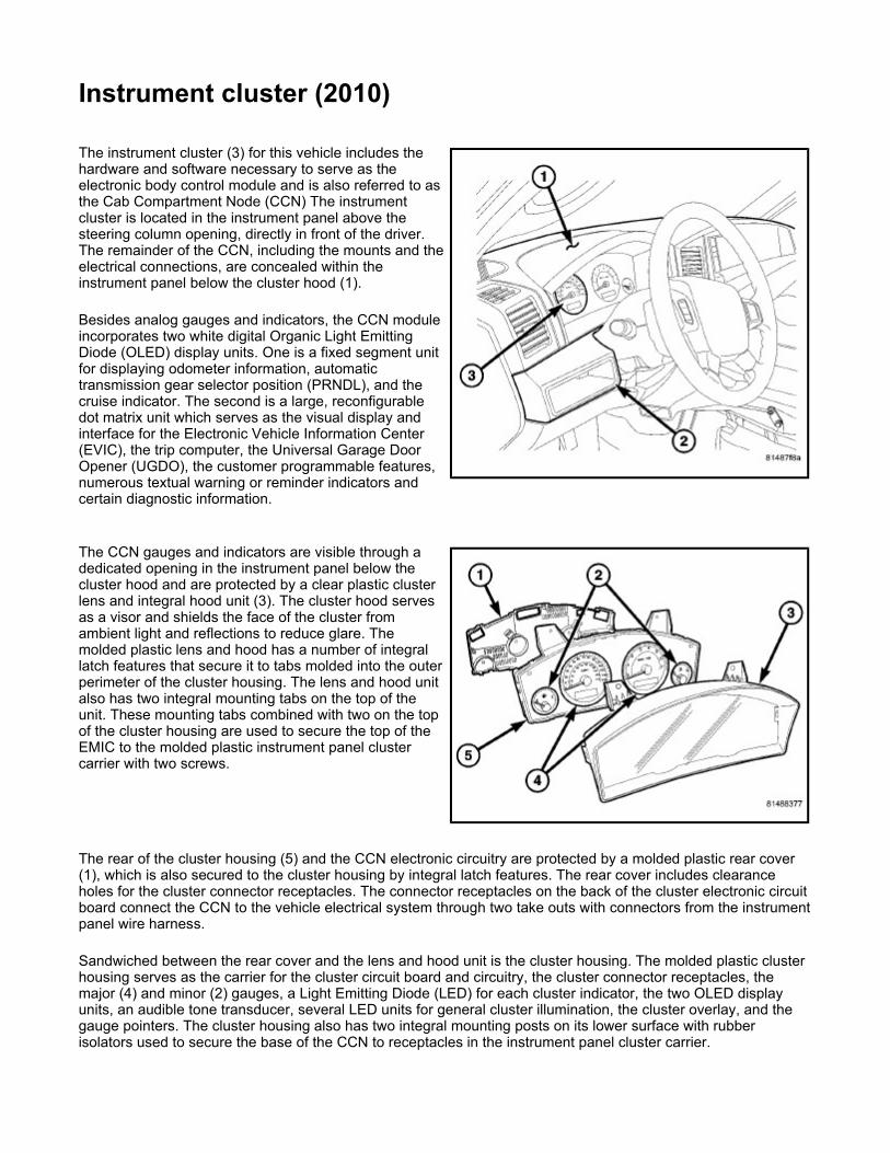
Instrument cluster (2010) The instrument cluster (3) for this vehicle includes the hardware and software necessary to serve as the electronic body control module and is also referred to as the Cab Compartment Node (CCN) The instrument cluster is located in the instrument panel above the steering column opening, directly in front of the driver. The remainder of the CCN, including the mounts and the electrical connections, are concealed within the instrument panel below the cluster hood (1).
Besides analog gauges and indicators, the CCN module incorporates two white digital Organic Light Emitting Diode (OLED) display units. One is a fixed segment unit for displaying odometer information, automatic transmission gear selector position (PRNDL), and the cruise indicator. The second is a large, reconfigurable dot matrix unit which serves as the visual display and interface for the Electronic Vehicle Information Center (EVIC), the trip computer, the Universal Garage Door Opener (UGDO), the customer programmable features, numerous textual warning or reminder indicators and certain diagnostic information.
The CCN gauges and indicators are visible through a dedicated opening in the instrument panel below the cluster hood and are protected by a clear plastic cluster lens and integral hood unit (3). The cluster hood serves as a visor and shields the face of the cluster from ambient light and reflections to reduce glare. The molded plastic lens and hood has a number of integral latch features that secure it to tabs molded into the outer perimeter of the cluster housing. The lens and hood unit also has two integral mounting tabs on the top of the unit. These mounting tabs combined with two on the top of the cluster housing are used to secure the top of the EMIC to the molded plastic instrument panel cluster carrier with two screws.
The rear of the cluster housing (5) and the CCN electronic circuitry are protected by a molded plastic rear cover (1), which is also secured to the cluster housing by integral latch features. The rear cover includes clearance holes for the cluster connector receptacles. The connector receptacles on the back of the cluster electronic circuit board connect the CCN to the vehicle electrical system through two take outs with connectors from the instrument panel wire harness.
Sandwiched between the rear cover and the lens and hood unit is the cluster housing. The molded plastic cluster housing serves as the carrier for the cluster circuit board and circuitry, the cluster connector receptacles, the major (4) and minor (2) gauges, a Light Emitting Diode (LED) for each cluster indicator, the two OLED display units, an audible tone transducer, several LED units for general cluster illumination, the cluster overlay, and the gauge pointers. The cluster housing also has two integral mounting posts on its lower surface with rubber isolators used to secure the base of the CCN to receptacles in the instrument panel cluster carrier.

The cluster overlay is a laminated plastic unit. On Laredo vehicles, the dark, visible, outer surface of the overlay is marked with all of the gauge dial faces and graduations, but this layer is also translucent. On Limited, Overland and SRT8 vehicles, the argent silver outer surface of the overlay appears unmarked. The darkness of this outer layer prevents the cluster from appearing cluttered or busy by concealing the cluster indicators (and the gauges on Limited, Overland and SRT8 vehicles) that are not illuminated, while the translucence of this layer allows those items that are illuminated to be readily visible. The underlying layer of the overlay is opaque and allows light from the LED for each of the various indicators and illumination lamps behind it to be visible through the outer layer of the overlay only through predetermined stencil-like cutouts. Rectangular openings in the overlay at the base of the speedometer and tachometer dial faces have smoked clear lenses through which the illuminated OLED display units can be viewed.
Several versions of the CCN module are offered on this vehicle. These versions accommodate all of the variations of optional equipment and regulatory requirements for the various markets in which the vehicle is offered. The microprocessor-based CCN utilizes integrated circuitry and information carried on the Controller Area Network (CAN) data bus and the Local Interface Network (LIN) data bus along with several hardwired analog and multiplexed inputs to monitor sensors and switches throughout the vehicle. In response to those inputs, the internal circuitry and programming of the CCN allow it to control and integrate many electronic functions and features of the vehicle through both hard wired outputs and the transmission of electronic message outputs to other electronic modules in the vehicle over the CAN and LIN data busses.
Besides typical instrument cluster gauge and indicator support, the electronic functions and features that the CCN supports or controls include the following:
A/C Select and Evaporator Probe Support - The CCN monitors A/C select switch and evaporator temperature sensor hardwired inputs from the Manual Temperature Control (MTC) control or electronic messages received over the CAN data bus from the Automatic Temperature Control (ATC) control, then transmits electronic A/C clutch request messages when appropriate to support the A/C clutch control feature.
Audible Warnings - The CCN electronic circuit board is equipped with an audible tone transducer and programming that allows it to provide various audible alerts to the vehicle operator. These alerts include single chime tones and continuous slow or fast tones. An electromechanical relay is also soldered onto the circuit board to produce audible clicks that are used to emulate the sound of a conventional turn signal or hazard warning flasher.
Automatic Headlamps Support - On vehicles equipped with optional automatic headlamps, the EMIC calculates the average ambient light level based upon an electronic message received over the CAN data bus from the Rain Sensor Module (RSM) on the windshield below the automatic day/night inside rear view mirror mounting button, then transmits an electronic auto headlamps request message when appropriate to support the automatic headlamps feature.
Electric Backlight Status Support - On vehicles equipped with optional Automatic Temperature Control (ATC), the CCN monitors electronic Electric BackLight (EBL) status messages received over the CAN data bus from the ATC control, then transmits electronic EBL status messages when appropriate to support the EBL feature.
Electronic Vehicle Information Center Support - In addition to the dot matrix Organic Light Emitting Diode (OLED) display, the CCN provides support for each of the functions and features of the Electronic Vehicle Information Center (EVIC). This includes support for the compass, thermometer, audio system mode, customer programmable features, textual warnings, premium Tire Pressure Monitor (TPM), trip computer, U-Connect™ Hands-Free communication, HomeLink™ Universal Garage Door Opener (UGDO) and the steering wheel switch electronic message inputs received over the Local Interface Network (LIN) data bus that are used to control and configure many of the EVIC displays. This also includes display arbitrator programming, which controls the priorities, sequences, and transition of information that is displayed in the EVIC, particularly when multiple display requests are received simultaneously.
Enhanced Accident Response Support - The CCN monitors an input from the Occupant Restraint Controller (ORC) and, following an airbag deployment, will immediately disable the power lock output, unlock all doors by activating the power unlock output, then enables the power lock output if the power lock switch input remains inactive for two seconds. The CCN also monitors an input from the Powertrain Control Module (PCM) to automatically turn ON the interior lighting after an airbag deployment event, 10 seconds after the vehicle speed is zero. The interior lighting remains illuminated until the ignition switch is turned to the OFF position, at which time the interior lighting returns to normal operation and control. These Enhanced Accident Response System (EARS) features are each dependent upon a functional vehicle

electrical system following the vehicle impact event. Exterior Lighting Switch Support - The CCN monitors electronic exterior lighting switch, and turn
signal switch status messages from the Steering Control Module (SCM) on the steering column over the LIN data bus and transmits the appropriate electronic exterior lighting and turn signal request messages to the Front Control Module (FCM) located on the Integrated Power Module (IPM) over the CAN data bus to support the exterior lighting functions.
Fuel Level Data Support - The CCN provides a current source for and receives a hard wired analog input from the fuel level sending unit located on the fuel pump module in the fuel tank. The CCN uses this input to calculate the proper fuel gauge needle position and to control low fuel indicator operation. Based upon this input, the CCN also uses electronic messaging to transmit this data over the CAN data bus for use by other electronic modules in the vehicle.
Heated Seat Switch Support and Switch Indicator Control - On vehicles equipped with optional heated seats, the CCN monitors electronic heated seat switch status messages from the front heated seat switches in the instrument panel switch pod and hard wired inputs from the rear heated seat switches and transmits electronic heated seat request messages over the CAN data bus. This message wakes up the Heated Seat Module (HSM) when the switch is actuated. The CCN then monitors electronic messages received over the CAN data bus from the HSM to send electronic status messages over the LIN data bus back to the lower switch pod to control front heated seat switch Light Emitting Diode (LED) indicators and uses a high side driver output to control the appropriate rear heated seat switch LED indicators.
Hill Descent Switch Support and Switch Indicator Control - On vehicles equipped with the optional hill descent system, the CCN monitors electronic hill descent switch status messages from the hill descent switch in the instrument panel switch pod over the LIN data bus and transmits electronic hill descent switch request messages to the Controller Anti-lock Brake (CAB) over the CAN data bus. This message tells the CAB whether the system should be enabled or disabled when the switch is actuated. The CCN then monitors electronic messages received over the CAN data bus from the CAB and transmits electronic messages to the instrument panel switch pod over the LIN data bus to control the hill descent switch Light Emitting Diode (LED) disable indicator.
Ignition On and Ignition Accessory/On Relay Control - The CCN monitors electronic ignition switch status messages received over the CAN bus from the Wireless Ignition Node (WIN) and a hardwired input from the ignition switch on the instrument panel, and provides low side driver outputs to control both the ignition ON and ignition ACCESSORY/ON relays in the Junction Block (JB) as appropriate.
Interior Lamp Load Shedding - The CCN provides a battery saver feature which will automatically turn OFF all interior lamps if they remain ON after a timed interval of about eight minutes.
Interior Lighting Control - The CCN monitors electronic messages and hard wired inputs from the interior lighting switch, the door ajar switches, the liftgate ajar switch, the liftgate flip-up glass ajar switch, the reading lamp switches and the WIN to provide courtesy lamp control. This includes support for timed illuminated entry with theater-style fade-to-OFF and courtesy illumination DEFEAT features.
Local Interface Network Master Module - The CCN is the master module for the LIN data bus. In this role it gathers information from the compass sensor, the Heated Seat Module (HSM), the instrument panel switch pods, the steering wheel switches and the SCM, then either acts on that information directly or places electronic messages on the CAN data bus for use by other modules
Panel Lamps Dimming Control - The CCN monitors electronic dimming level messages received from the panel lamps dimmer switch input to the SCM over the LIN data bus, then provides both a hard wired 12-volt Pulse-Width Modulated (PWM) output and electronic message outputs over the LIN data bus that synchronizes the dimming level of all panel lamps dimmer controlled lamps with that of the cluster general illumination lighting.
Park Assist Switch Support and Switch Indicator Control - On vehicles equipped with the optional park assist system, the CCN monitors electronic park assist switch status messages from the park assist switch in the instrument panel switch pod over the LIN data bus and transmits electronic park assist switch request messages to the park assist module over the CAN data bus. This message tells the park assist module whether the system should be enabled or disabled when the switch is actuated. The CCN then monitors electronic messages received over the CAN data bus from the park assist module and transmits electronic messages to the instrument panel switch pod over the LIN data bus to control the park assist switch Light Emitting Diode (LED) disable indicator.
Power Inverter Support - The CCN monitors a hardwired input from the power inverter to determine the inverter status, then transmits electronic inverter status messages to other electronic modules in the vehicle over the CAN data bus.
Power Lock System Control - The CCN monitors inputs from the power lock switches and the WIN to provide control of the power lock motors through high side and low side driver outputs. This includes support for rolling door locks (also known as automatic door locks), automatic door unlock, and a door lock inhibit mode.

Remote Keyless Entry Support - The CCN supports the Remote Keyless Entry (RKE) system features, including support for the RKE LOCK, UNLOCK (with optional driver-door-only unlock, and unlock-all-doors), PANIC, audible chirp, optical chirp, illuminated entry modes, an RKE programming mode, as well as optional Vehicle Theft Security System (VTSS) arming (when the proper VTSS arming conditions are met) and disarming.
Remote Radio Switch Support - The CCN receives electronic message inputs from the remote radio switches on the steering wheel over the LIN data bus, then provides electronic radio request messages over the CAN data bus to support the remote radio switch function.
Remote Start System Support - The CCN receives electronic message inputs from the WIN and then displays the appropriate remote start system textual reminder messages to the vehicle operator within the CCN dot matrix display.
Steering Wheel Switch Support - The CCN receives electronic message inputs from the steering wheel switches on the steering wheel over the LIN data bus to control and configure many of the EVIC displays and functions.
Vehicle Theft Security System Control - The CCN monitors inputs from the door ajar switches, and the WIN, on vehicles so equipped. The intrusion module then provides electronic horn and lighting request messages to the Front Control Module (FCM) located on the Integrated Power Module (IPM) for the appropriate VTSS alarm output features.
Wiper and Washer Switch Support - The CCN monitors electronic wiper switch and washer switch status messages from the SCM on the steering column over the LIN data bus and transmits the appropriate electronic wiper and washer request messages to the FCM located on the IPM over the CAN data bus to support the wiper and washer system functions, including the headlamps-on with wipers programmable feature.
Except With Diesel Engine Or Rear Fog Lamps
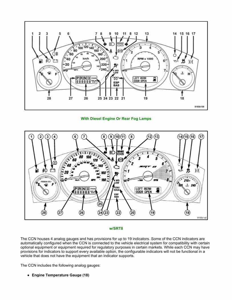
The CCN houses 4 analog gauges and has provisions for up to 19 indicators. Some of the CCN indicators are automatically configured when the CCN is connected to the vehicle electrical system for compatibility with certain optional equipment or equipment required for regulatory purposes in certain markets. While each CCN may have provisions for indicators to support every available option, the configurable indicators will not be functional in a vehicle that does not have the equipment that an indicator supports.
The CCN includes the following analog gauges:
Engine Temperature Gauge (18)
With Diesel Engine Or Rear Fog Lamps
w/SRT8

Fuel Gauge (28) Speedometer (6) Tachometer (13)
The CCN includes the following OLED display units:
Dot Matrix Display (19) - Electronic Vehicle Information Center (EVIC), Trip Odometer A and B, and Textual Messages
Fixed Segment Display - Includes Gear Selector Indicator (27), Odometer (26) and Cruise Indicator (25)
The CCN includes provisions for the following indicators:
Adjustable Pedal System Indicator - textual messages in dot matrix display (19) Airbag Indicator (24) Ajar Indicators - textual messages and icon in dot matrix display (19) for doors, hood, liftgate and liftgate
flip-up glass Antilock Brake System (ABS) Indicator (12) Brake Indicator (11) Change Oil Indicator - textual message in dot matrix display (19) on domestic market vehicles only Charging Indicator (3) Check Gauges Indicator - textual message in dot matrix display (19) Check Shift Procedure Indicator - textual message in dot matrix display (19) Coolant Low Indicator - textual message and icon in dot matrix display (19) Cruise Indicator (25) - text in fixed segment display Electronic Stability Program (ESP)/Brake Assist System (BAS) Indicator (22) - and textual messages
in dot matrix display (19) Electronic Throttle Control (ETC) Indicator (17) Four-Wheel Drive Low Indicator (23) Four-Wheel Drive System In Neutral Indicator - textual message and icon in dot matrix display (19) Front Fog Lamp Indicator (2) Gas Cap Indicator - textual message in dot matrix display (19) Gear Selector Indicator (27) High Beam Indicator (9) Hill Descent Indicator - textual message in dot matrix display (19) Low Brake Fluid Level Indicator - textual message in dot matrix display (19) Low Fuel Indicator (1) - or within the fuel gauge (28) dial face on Limited and Overland vehicles
manufactured for certain export markets. Low Oil Pressure Indicator (15) Malfunction Indicator Lamp (MIL) (10) Memory System Indicator - textual messages in dot matrix display (19) No Bus Indicator - textual message in dot matrix display (19) No Fuse Indicator - textual message in dot matrix display (19) Oil Pressure Indicator (SRT8 only) - textual message and icon in dot matrix display (19) Oil Temperature Indicator (SRT8 only) - textual message and icon in dot matrix display (19) Park Assist Disabled Indicator - textual message in dot matrix display (19) Perform Service Indicator - textual message in dot matrix display (19) with diesel only Position Lamp Indicator (1) - on Limited and Overland vehicles manufactured for certain export markets. Power Liftgate Indicator - textual messages in dot matrix display (19) Rear Fog Lamp Indicator (5) - in markets where rear fog lamps are available only Remote Start Indicator - textual messages in dot matrix display (19) Seat Belt Indicator (7) Security Indicator (14) - also textual messages for Sentry Key Immobilizer System (SKIS) in dot matrix
display (19) Service Column Lock Indicator - textual message in dot matrix display (19) Service Exhaust Indicator - textual message in dot matrix display (19) with diesel only Service Four-Wheel Drive System Indicator - textual message in dot matrix display (19) Service Park Assist System Indicator - textual message in dot matrix display (19) SmartBeam® (Auto High Beam) Indicator - textual messages in dot matrix display (19) Tire Pressure Monitor (TPM) Indicator (4) - may also include textual messages in dot matrix display (19) Tow/Haul Indicator (20)

Traction Control/Electronic Stability Program (ESP) Indicator (16) Transmission Overtemp Indicator - textual message in dot matrix display (19) Turn-Signal-On Reminder Indicator - textual message and icon in dot matrix display (19) Turn Signal (Right and Left) Indicators (8) Upshift Indicator (SRT8 only) - textual message and icon in dot matrix display (19) Wait-To-Start Indicator (21) - with diesel only Washer Fluid Indicator - textual message and icon in dot matrix display (19) Water-In-Fuel Indicator - textual message in dot matrix display (19) with diesel only
Each indicator in the instrument cluster, except those located within an OLED display unit, is illuminated by a dedicated LED that is soldered onto the CCN electronic circuit board. Cluster illumination is accomplished by several dimmable LED units, which illuminate each of the Laredo gauge dial faces for visibility whenever the exterior lighting is turned ON, or the Limited and Overland gauge dial faces whenever the ignition is turned ON. These LED units are not available for service replacement and, if damaged or ineffective, the entire unit must be replaced.
Hard wired circuitry connects the CCN to the electrical system of the vehicle. These hard wired circuits are integral to several wire harnesses, which are routed throughout the vehicle and retained by many different methods. These circuits may be connected to each other, to the vehicle electrical system and to the CCN through the use of a combination of soldered splices, splice block connectors, and many different types of wire harness terminal connectors and insulators. Refer to the appropriate wiring information. The wiring information includes wiring diagrams, proper wire and connector repair procedures, further details on wire harness routing and retention, as well as pin-out and location views for the various wire harness connectors, splices and grounds.
The CCN module for this vehicle is serviced only as a complete unit. The CCN module cannot be adjusted or repaired. If a gauge, an LED unit, an OLED display unit, the electronic circuit board, the circuit board hardware, the cluster overlay, or the cluster housing are damaged or ineffective, the entire CCN module must be replaced. The cluster lens, hood and mask unit is available for separate service replacement.