Instructions - Mamiya Leaf Medium Format Digital Backs and ... · Mirro rLock-u pPhotography. ......
46
Instructions
Transcript of Instructions - Mamiya Leaf Medium Format Digital Backs and ... · Mirro rLock-u pPhotography. ......

Instructions

Congratulations on your purchase of the Mamiya 645 PRO TL
Mamiya pioneered the 6 x 4.5 film format and introduced the world’s first 645SLR in 1975. The 645 PRO TL is the latest masterpiece in this series andIncorporates all the latest mechanical, electronic and optical advances. Itsexternal appearance, too, has been modernized and its ergonomic designfurther enhanced.We are sure that you will enjoy the many advantages this camera and itsaccessories offer and want to particularly mention :The 645 PRO TL has a built-in self-timer (delayed shutter release) which willalso facilitate time exposures. Attaching special leaf shutter lenses willautomatically set the focal plane shutter to 1/8 sec. Heavy duty gears connectto the improved Power Drive Grip WG401, This grip also automatically cocksthe leaf shutter lenses and permits remote control.The AE Prism Finder FE401, specially created for this camera, automatesexposure and shows LED safety signals. 35mm film holders now come withpanoramic adapters. A super fast 300mm f/2.8 APO lens was also designedfor this camera.We are convinced that your camera will serve you well, because we havedesigned it for heavy professional use. However, we ask you to please read alloperating instructions carefully before you put your equipment to work, inorder to ensure proper operation and maximum results
This manual covers the basiccamera. Separate instructionsare supplied with all systemaccessories, including lenses,finders, film holders, etc.For additional informationplease feel free to contact yourauthorized Mamiya dealer orthe Mamiya importer in yourcountry.

Contents
Special Features of the Mamiya 645 PRO TL ....... 3Names and Functions of Parts .............................. 7Attaching and Removing Lenses ........................ 10Attaching and Removing the Roll Film Holders. 11Attaching and Removing the Viewfinder ............ 12Removing and Attaching the Film AdvanceCrank ...................................................................... 13Inserting the Battery ............................................. 14Battery Check ........................................................ 15Shutter Release Selector ...................................... 16Shutter Performance Test .................................... 17Before Film Loading ............................................. 16Film Loading .......................................................... 19Advancing the Film to the First Frame.. .............. 21Shutter Speed Settings. ........................................ 22Aperture Ring/Stop-down Operation.. ................. 23Focusing ................................................................ 24
Depth of Field ........................................................ 25Film Advance and Unloading Exposed Film ...... 26Using the Self-timer/Delayed Shutter Release.. 27Time Exposures .................................................... 26Multiple Exposures ............................................... 26Mirror Lock-up Photography.. .............................. 29Infrared Photography.. .......................................... 30Using a Tripod ....................................................... 30Flash Photography.. .............................................. 31Holding the Camera Steady and Securely.. ........ 35Attaching and Removing the Neck Strap.. .......... 36Basic Accessories ................................................ 37System Chart ......................................................... 39Trouble Shooting .................................................. 40Mamiya 645 PRO TL Specifications .................... 41Things to Watch .................................................... 43Common Sense Camera Care and Practice ....... 44

Special Features of the Mamiya 645 PRO TL
1. Image Area about 3X larger than 35mm Format 3. Interchangeable Rollfilm Holder System
- Bigger is better --The 6X4.5cm image size is about 3x larger than 35mmand therefore produces far superior results. It is largeenough to be viewed without magnifier and its aspectratio of about 1.25 (long side : short side) matches thestandard 8 x 10 inch “ideal format”, the most popular inphotography and industrial use. It requires minimumcropping and gives maximum film utilization. (15 or 30exposures on 120 or 220 film respectively)
-120, 220, 35mm, 35mm Panoramic and Polaroid --Permits quick film change, even in mid-roll. Many failsafe features prevent accidental exposures or film waste.
2. Rugged, Versatile and Reliable Camera Body
- Built for professional use --Mamiya pioneered the 645 SLR camera system in 1975to create medium format image quality with 35mmhandling ease. New models have periodically followedover the years to keep in step with mechanical, opticaland electronic advances
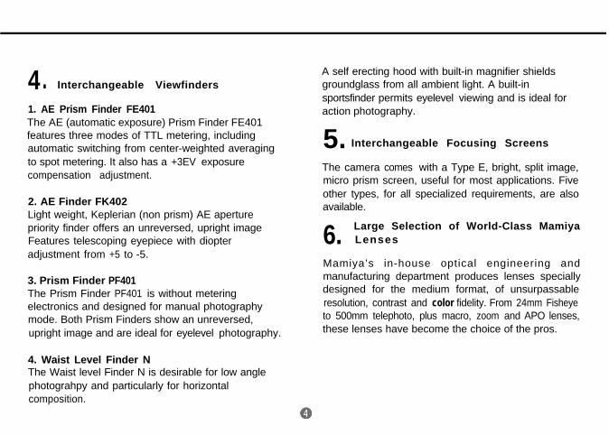
4. Interchangeable Viewfinders
1. AE Prism Finder FE401The AE (automatic exposure) Prism Finder FE401features three modes of TTL metering, includingautomatic switching from center-weighted averagingto spot metering. It also has a +3EV exposurecompensation adjustment.
2. AE Finder FK402Light weight, Keplerian (non prism) AE aperturepriority finder offers an unreversed, upright imageFeatures telescoping eyepiece with diopteradjustment from +5 to -5.
3. Prism Finder PF401The Prism Finder PF401 is without meteringelectronics and designed for manual photographymode. Both Prism Finders show an unreversed,upright image and are ideal for eyelevel photography.
4. Waist Level Finder NThe Waist level Finder N is desirable for low anglephotograhpy and particularly for horizontalcomposition.
A self erecting hood with built-in magnifier shieldsgroundglass from all ambient light. A built-insportsfinder permits eyelevel viewing and is ideal foraction photography.
5. Interchangeable Focusing Screens
The camera comes with a Type E, bright, split image,micro prism screen, useful for most applications. Fiveother types, for all specialized requirements, are alsoavailable.
6. Large Selection of World-Class Mamiya Lenses
Mamiya’s in-house optical engineering andmanufacturing department produces lenses speciallydesigned for the medium format, of unsurpassableresolution, contrast and color fidelity. From 24mm Fisheyeto 500mm telephoto, plus macro, zoom and APO lenses,these lenses have become the choice of the pros.

7. Motorized Power Drive Grips
Two accessory motorized drives, interchangeable withthe manual film advance crank, are incorporated into anergonomically designed grips for easy, right handedcamera operation.
Model WG 401 requires 6 AA batteries and featuresmultiple exposure switch, cable release socket, batterycheck and continuous shooting. It also can be used withleaf shutter lenses.
Model WG402, a simplified version, permits onlyindividual exposures, uses one 6 Volt lithium battery andis much lighter.
8 . A Broad Accessory SystemFor Specialized Applications
A useful accessory system to serve the specializedneeds of the photographer. It includes Auto Bellows andAuto Extension Rings for close-up and copying work;Infrared Remote Control for studio and naturephotography; External Battery Case for operating in coldsurroundings; Camera Grips for convenient holding andmore.
<Self-timer>Self-timer for delayed shutter release. When activated itwill light a red pilot lamp in the front of the camera foreight seconds and will blink for two seconds beforetriggering the shutter.
<Time Exposure>Time exposures are made by utilizing the Self-timer andthe "B" shutter setting. A new power saving circuitdesign switches the battery off and extends is life.
9 TTL (through-the-lens) Flash Exposure. Automation
The light that hits the film surface during exposure isreflected to a photoreceptor within the camera bodywhich automatically adjusts the flash output to therequired level.

10. Other Features
<Mirror Lock-up>After focusing, the mirror can be locked up beforemaking an exposure. This is convenient when thecamera is used at slow shutter speeds and is mountedon a tripod for telephotography, copywork, etc.,since even a very small amount of vibration shouldbe eliminated.
<Self-timer>Shutter will be released 10 seconds after shutterbutton is pressed.
<Time Exposure>When making time exposures, the battery circuit isautomatically disconnected, to save battery power.This is especially useful for astrophotography.

Names and Functions of Parts @
Focusing Screen N
Aperture Ring CouplingThis pin is fitted into the EMeter Coupler of the ltransmit the aperture datAE Prism Finder.
Battery Check Lamp
13 Gold Plated ContactsThese contacts interface the AEPrism Finder with the IS0 dial onthe film holder and the shutterspeeds.
Hot-shoe (X contact)A cordless flash can be used with
Focusing Screen Release PinWhen you want to change thescreen, slide this pin to the leftand remove the screen.
Shutter Release SelectorAlign the white index dot on theselector collar with the whitesquare dot in the center for normaluse. When the collar is turned tothe red dot, the release is locked.To use the Self-timer, set it to e..
this shoe.
Flash Sync TerminalFlash cord and optional TerminalAdapter RA401 can be connectedto this terminal.
Shutter Release Button
Mirrorl Never touch the surface of themirror
left, the contact appears. Thiscontact is used for connections ofexternal releases such as a
Battery Check Button /LED displays the present batterycondition.
\ tro’ u”it.6- Pin Coupling Connector ford e d i c a t e d T T L f l a s h
0
automation. (Such as MetzSCA396)
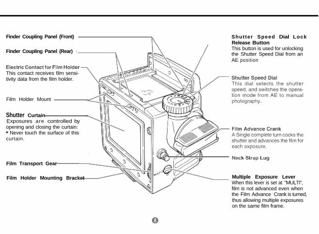
Finder Coupling Panel (Front)tl
Shutter Speed Dial LockRelease Button
Finder Coupling Panel (Rear)
’
This button is used for unlocking
/
the Shutter Speed Dial from anAE posit ion
This contact receives film sensi-tivity data from the film holder.
Film Holder Mount
Shutter CurtainExposures are controlled byopening and closing the curtain:a Never touch the surface of thiscurtain.
Film Transport Gear -
Film Holder Mounting Bracket Multiple Exposure LeverWhen this lever is set at "MULTI",film is not advanced even whenthe Film Advance Crank is turned,thus allowing multiple exposureson the same film frame.

Tripod Socket
1/4’ tripod socket. To convert toa 3/8’ socket, remove the smallscrew in the base of the socket.Then remove the bushing. Seepage 32.
Distance ScaleThe camera to subject distancecan be set or confirmed with thisscale
Lens Alignment Dot
Depth-of-field ScaleProvides a quick reading of depth-of-field for various apertures anddistances.
Exposure Meter CouplerThis coupler is engaged with theAperture Ring Coupling Pin, trans-mitting diaphragm information tothe AE PrismFinder.

@ Attaching and Removing Lenses 0Removing the Front Body Capand Rear Cover Attaching the Lens
First remove the Front Body Cap inthe direction of the arrow, while push-ing the Lens Release Button 8backwards as indicated by arrow.Rear Body Protective Cover can bereadily removed by depressing thepart of @ as shown in the illustra-tion.
Line up red Lens Alignment Dot 0against red camera Alignment Dot $3and gently insert the lens into thecamera body. Then turn the lensclock wise, as indicated by arrow,until it clicks into place. Make surethat the Aperture Ring Coupler Pin isengaged with the Exposure MeterCoupling Pin @I,, which sticks outunder the Mamiya name plate of thecamera.
Removing the Lens.
While pushing lens release button @backwards, turn lens counter-clockwise. (Same procedure asremoving body cap).

Attaching and Removing the Roll Film Holder
Removing the Rear Body Cap
Rear Body Protective Cover can bereadily removed by depressing thepart of 0 as shown in the illustration.
*After removing the rear cap, becareful not to touch the shutterblind. This can cause breakage ofshutter.
Attaching the Roll Film Holder
* Remove the Roll Film HolderCover.1. While spanning the Roll Film Holderbetween your thumb and middle fin-ger, holding it on the rubberized fin-ger rests, carefully align its FilmHolder Mounting Bracket with thecorresponding center clip of the cam-era body.
2. While keeping this alignment, pressthe upper part of the Roll Film Holderagainst the camera body, so that itclicks into place by engaging thespring loaded twin camera catch.

Attaching and Removing the Viewfinder
Removing the Roll Film Holder
1. Insert the Dark slide into the slotmarked by White Lines on the side ofthe holder.2. Push the lower one of the FilmHolder Detaching Lock ReleaseButton @ downward, while simulta-neously pushing the Film HolderDetaching Button @$ inward.
* If the Dark Slide is not inserted,the safety lock will prevent theholder from being removed.
Attaching the Finder.
Lift the Upper Cover from the camerabody.Insert the Attaching Latches of thefinder into the Finder Coupling Panel@I in the front wall of the body. Pressthe finder down until the rear latchlocks securely in place.
Removing the Finder
Spanning the finder with your fin-gers, push the button on its right sidemarked with a downward pointingarrow @ @I, downward, whilepushing the other button, on the leftside @ 0, inward.
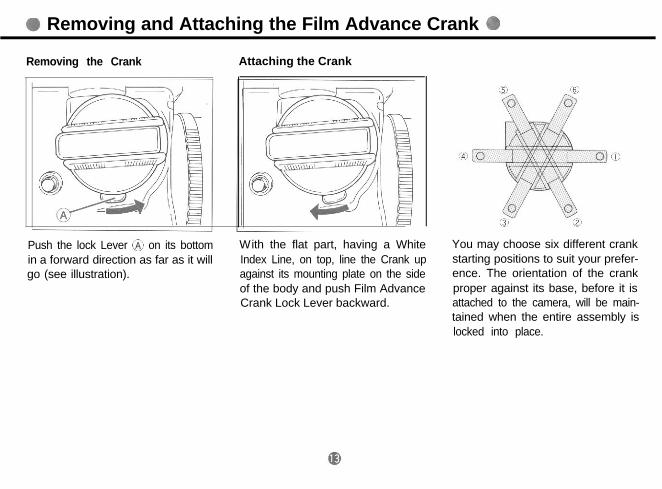
Removing and Attaching the Film Advance Crank
Removing the Crank Attaching the Crank
Push the lock Lever ‘&> on its bottomin a forward direction as far as it will
With the flat part, having a White
go (see illustration).Index Line, on top, line the Crank upagainst its mounting plate on the sideof the body and push Film AdvanceCrank Lock Lever backward.
You may choose six different crankstarting positions to suit your prefer-ence. The orientation of the crankproper against its base, before it isattached to the camera, will be main-tained when the entire assembly islocked into place.
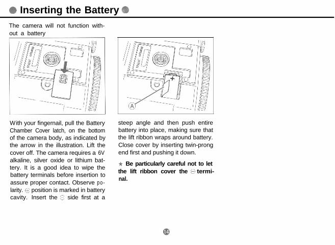
0 Inserting the BatteryThe camera will not function with-out a battery
With your fingernail, pull the BatteryChamber Cover latch, on the bottomof the camera body, as indicated bythe arrow in the illustration. Lift thecover off. The camera requires a 6Valkaline, silver oxide or lithium bat-tery. It is a good idea to wipe thebattery terminals before insertion toassure proper contact. Observe po-larity. Q position is marked in batterycavity. Insert the G side first at a
steep angle and then push entirebattery into place, making sure thatthe lift ribbon wraps around battery.Close cover by inserting twin-prongend first and pushing it down.
* Be particularly careful not to letthe lift ribbon cover the c” termi-nal.

Batterv Check
Press Battery Check Button “B.C.”8 on lower front of the camera.Battery Check Lamp @I on top oppo-site side should light. Bright light indi-cates good condition. Blinking lightmeans replace battery. No lightmeans battery is dead or improperlyinserted.
Important:1. The sealed, new battery which issupplied with this camera may havebeen subject to storage conditionswhich have reduced its service life.Therefore it is desirable to replace itwith a fresh battery as soon aspossible.2. Carefully wipe the battery contactsbefore inserting into the chamber.Failure to do so may result in poorelectrical contact and consequentmalfunctioning of the camera.3. Always remove battery whencamera is not used for a while. Alwayscarry spare batteries.4. Battery life differs, depending ontype, age. storage condition, ambienttemperature, frequency Of use etc.
Battery strength will be indicatedby whether the light:
Glows ... Battery stength issufficient.
Blinks ... Battery capacity hasdropped below theallowable level.
(Replace thebattery.)
Does not light .,..... The camerawill not work. (Replacethe battery.)

Shutter Release Selector
For normal operation set the WhiteDot of the Shutter Release Selector(8 against the White Square Dot 0.When set to the Red Dot 0, theRelease Button is locked.
* Select this mode if the camerawill be idle for a period and toprevent accidental shutter release.Also when the Power Drive Grip isused.
When set to the yellow clock symbol 3. After releasing the shutter, theti’ the self-timer is operative. See Film Advance Crank will automati-page 27 and 28 for further instruc- cally unlock and be ready to advancetions. the film.
Operating the Shutter ReleaseButton1. The Shutter Release Button SJfunctions in two steps. Gentle pres-sure will light the metering informa-tion display if the AE Prism Finder isused. Continued pressure will releasethe electromagnetic shutter.2. If the film is not completely ad-vanced, if the Dark Slide is not with-drawn or if the battery is dead, theshutter will not function, even whenthe Shutter Release Button ispressed. This will also be the case ifthe Shutter Speed Dial is set to “A” or“AEL” when the AE Prism Finder isnot attached.
a3

Shutter Performance Test
1. Attach the Roll Film Holder to thecamera body.2. Pull out the Dark Slide and place itinto its Storage Slot.
3. Set the Shutter Speed Dial to anyother position than ‘A”or “AEL”. Whenthe AE Prism Finder is not mountedon the camera, the shutter will notrelease if the Shutter Speed Dial is inthe “A” or “AEL” position,
the film holder is supplied with avinyl tube. When placed in thetake-up compartment it engagesthe film sensor and makes theholder function as if it is loadedwith film. Please remove the tube
4. Set the Multiple Exposure Leveron the body to the “MULTI” position.
Before Film Loading
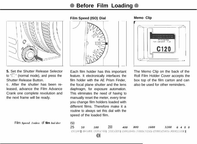
5. Set the Shutter Release Selectorto " 0 " (normal mode), and press theShutter Release Button.6. After the shutter has been re-leased, advance the Film AdvanceCrank one complete revolution andthe next frame will be ready.
Film Speed Index Speed Index of film holderholder
Film Speed (ISO) Dial Memo Clipr
L
! I,I- -The Memo Clip on the back of theRoll Film Holder Cover accepts thebox top of the film carton and canalso be used for other reminders.
Each film holder has this importantfeature. It electronically interfaces thefilm holder with the AE Prism Finder,the focal plane shutter and the lensdiaphragm, for exposure automation.This eliminates the need of having tomanually reset the meter, every timeyou change film holders loaded withdifferent films. Therefore make it aroutine to always set this dial with thespeed of the loaded film.
IS025 50 100 50 100 200 400 400 800 1600 3200800 1600 3200 6 4 0 06 4 0 0(32)(40)(32)(40) (64)(80)(64)(80) (125)(1601(125)(1601 (X0)(320)(X0)(320) (5001(6401(10001(1250)(5001(6401(10001(1250) (2ooo)c25oo,(4oao)(sooo)(2ooo)c25oo,(4oao)(sooo)
00

Film Loading
1. While pushing the Back CoverLock Release Button 8 downward,press the Back Cover Opening But-ton @;:, and the Back Cover will open.
2. While squeezing in on both sides 3. Align the right-hand side of thisof the Release Latch CQ, pull the Roll empty spool with the lower SpoolFilm Insert out of the camera body. At Stud ‘8 (convex). Slide the spool intothat time, move the empty spool in position making sure that the left-the upper part down to the lower side of the spool is properly held byspool compartment the Spool Clip.
When you load film for the firsttime, remove and discard theprotective paper cover which isattached to the film rails in theroll film holder.

4. In the same manner, insert a roll offilm in the upper compartment. Atthat time, check that the film leaderpaper is set as shown in the photoabove. (The leader paper inside isfacing outward on the pressure plate.Note that the film direction is wrong ifthe leader paper is facing inward.)
5. Pull out some of the leader paper.Insert the tip of the leader paper intothe slot of the lower Take-up Spool.
6. Gently rotate the take-up spool asshown in the photo until the startmark on the leader paper is alignedwith the start mark (a) on the spoolclip.
* Correctly align the start markswith each other, making sure thatthe film feeds properly. When im-proper feeding occurs, the propernumber of exposures may not betaken.* Avoid exposing the film to di-rect sunlight when inserting or re-moving film.
@I
* 220 Film Loading Caution220 films have two types of StartMark Lines across the paperleader. Always use the second one,a solid line with the legend “StartMark for standard cameras”,located about 14cm (5 1/2”),behind the first, dotted Mark line.
DO NOT use the dotted line for astart mark.

Advancing the Film to the First Frame
7. Insert the loaded Roll Film Insertinto the holder, the film roll on top,while squeezing on both sides of theRelease Latch Cc as shown inillustration. Make sure that is beenproperly seated and is locked in place.Then close cover by firmly pressingits top against the Roll Film Holder.
* To close the Back Cover, firmlypress the top of the back cover onboth sides.
1 . While spanning the Roll Film Holderbetween your thumb and middle,.f inger holding itit on the rubberizedfinger rests, carefully align its FilmHolder Mounting Bracket with thecorresponding center clip of thecamera body.2. While keeping this alignment, pressthe upper part of the Roll Film Holderagainst the camera body, so that itclicks into place by engaging thespring loaded twin camera catch.
Set the multiple exposure switchinglever A to the white square mark 0(normal mode).

Shutter Speed Settings
I / I I
3. Wind up. How to set the Shutter Speed DialWind up the crank handle until it 1. Set the desired shutter speedstops. In the film counter window, the against the white index line (A) on thenumber 1 appears, and the film and shutter speed dial.shutter are set. 2. At the red “A" (for Automatic) and
AEL (for Automatic Lock) settings,the shutter speed dial is lockedbetween these two positions. Thesesettings will only function if an AEFinder is mounted on the camera. Torelease this lock push button (B) whileturning dial.3. All while numbers are fractionalseconds. (i.e. 30 =1/30 sec).
@
The yellow 2 and 4 are full seconds.“B” (shutter stays open as long as itis depressed) is also yellow.4. Red 60 is 1/60 sec. It is colored redto remind you that it is the fastestspeed useable with electronic flash.5. Note: When a Metz Electronic FlashUnit, together with SCA 396 module,is attached to the camera, the camerasets itself automatically to 1/60 sec.,irrespective of the dial setting.
* When manually selected shutterspeeds are set on the shutter speeddial, the intermediate shutterspeeds available in the AEoperation are not obtainable.
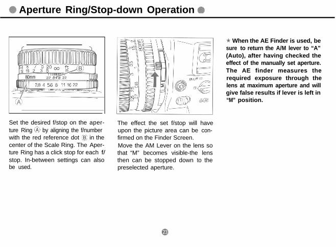
Aperture Ring/Stop-down Operation
Set the desired f/stop on the aper-ture Ring 6) by aligning the f/number
The effect the set f/stop will haveupon the picture area can be con-
with the red reference dot SC@ in the firmed on the Finder Screen.center of the Scale Ring. The Aper- Move the AM Lever on the lens soture Ring has a click stop for each f/ that “M” becomes visible-the lensstop. In-between settings can also then can be stopped down to thebe used. preselected aperture.
* When the AE Finder is used, besure to return the A/M lever to “A”(Auto), after having checked theeffect of the manually set aperture.The AE finder measures therequired exposure through thelens at maximum aperture and willgive false results if lever is left in“M” position.

0 Focusing 4B
While looking through the viewfinder,turn the lens Focusing Ring until themost important subject part appearssharp and clear.
Focusing with the Standard Focusing Screen N Type Er-
1. The camera comes equipped witha bright, Type E, Rangefinder/Micro-prism Focusing Screen. It features acenter, split-image rangefinder spotand the subject is in sharp focuswhen the split images combine intoone.2. The microprism ring around thesplit-image center further facilitatesfocusing. The microprisms disappearonly when the subject is in sharpfocus.
3. The rest of the ground glass areacan also be used for focusing.
* Interchangeable F o c u s i n gScreensThere are five additional focusingscreens available for specializedapplications. They are easy tointerchange and come with in-structions.

Depth of Field
Reading the Depth of Field ScaleDepth of field is defined as the zoneof sharpness before and behind theplane of focus. It depends on camerasubject/distance, focal length of lens,aperture setting and distance the lensis focused at.
~11 16 221 I
In addition to visual observation, theDepth of Field can be determined byusing the Depth of Field Scale oneach lens. f/stop numbers appear onboth the right and left side of the redindex mark in the center of the scalering. Simply read the figures whichappear above the f/stop numbers onthe distance scale of the lens.
For example, with the 80mm f/2.8Nlens focused at 3m and the apertureset at f/22, the depth of field scaleindicates that the zone of sharp focuswill extend from about 2m to 6m.

Film Advance and Unloading Exposed Film
Film Advance
1. Giving the Film Advance Crankone complete turn, will cock the shut-ter and mirror and ready the camera
2. When the film is completely ex-posed (15 exposures on 120, 30 on
for the next exposure.
220 film), the crank stop will disen-gage. Continue turning until the pa-per trailer is completely wound ontothe take-up spool. (About five turnsafter the last exposure.)
Unloading Exposed Film* Move the empty spool from thetop to the lower (take-up)compartment, ready for loadingthe next film roll.*Never load, unload or handle filmin direct sunlight.
3. Open the Back Cover, and removethe Roll Film Insert. The ExposureCounter will return to S (start)automatically.4. Pull the Spool Clip on the roll filminsert out to remove the film.5. Remove the film from the roll filminsert; make sure that the film on theroll does not loosen, and sealimmediately.
Using the Self-Timer/Delayed Shutter Release
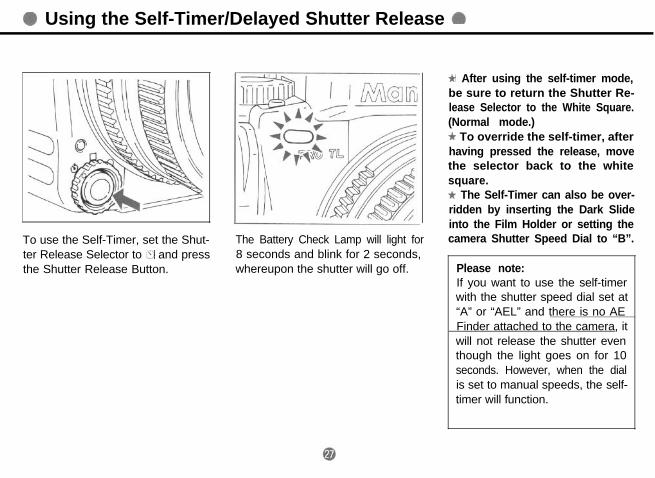
To use the Self-Timer, set the Shut-ter Release Selector to @ and pressthe Shutter Release Button.
The Battery Check Lamp will light for8 seconds and blink for 2 seconds,whereupon the shutter will go off.
* After using the self-timer mode,be sure to return the Shutter Re-lease Selector to the White Square.(Normal mode.)-k To override the self-timer, afterhaving pressed the release, movethe selector back to the whitesquare.* The Self-Timer can also be over-ridden by inserting the Dark Slideinto the Film Holder or setting thecamera Shutter Speed Dial to “B”.
Please note:If you want to use the self-timerwith the shutter speed dial set at“A” or “AEL” and there is no AEFinder attached to the camera, itwill not release the shutter eventhough the light goes on for 10seconds. However, when the dialis set to manual speeds, the self-timer will function.

Time Exposures Multiple Exposures
For time exposures set the ShutterRelease Selector to c, the self-timermode, and set the Shutter SpeedDial to "B". Press the shutter releaseand both mirror and shutter will stayopen until the shutter release ispressed again. You may also use acable release together with the cablerelease adapter. (The battery circuitwill automatically switch off to savepower.)
* "B" can be terminated by shift-ing the Shutter Release Selectorfrom 23 or the Shutter Speed Dialfrom "B"
Aligning the white dot of the MultipleExposure Lever with the yellow“MULTI” square, disengages the mul-tiple exposure prevention mecha-nism, and the film will not advanceafter an exposure is made and theFilm Advance Crank is turned.However, the shutter will be recocked,thus making multiple exposurespossible. In this mode the ExposureCounter will not advance.

Mirror Lock-up Photography
* To override the multiple expo-sure mode or to return to normaloperation, be sure to return thelever’s White Dot against the whitesquare and then advance the film.(If you forget you will continue tomake multiple exposures on thesame frame.)
This is an important feature when thetripod mounted camera is used atslow or long exposure times andparticularly also with use of longtelephoto lenses. It eliminates thepossibility of even the slightest “mir-ror bounce” which may affect imagesharpness.Move the Mirror look-up Lever to theyellow ”M.UP” square, after you havecomposed and focused your picture.This will raise the mirror and theviewfinder image will be blacked out.After use, return lever to normal (white
*When using the AE PrismFinder, set the Shutter Speed Dialto “AEL”. Press the shutter re-lease halfway and then lock themirror up. If set to “A” and themirror is locked up, “LT” (longtime) will appear in the finder dis-play and correct exposure cannotbe obtained.* When using a Leaf Shutter Lens,be sure to read the instructionsaccompanying it.
square) position.@

Infrared Photography @ Using aTripod @
Infrared light rays-being of longerwavelength - focus at a slightly dif-ferent plane and require the follow-ing adjustment:1. Note the Red Index Mark againstwhich you read your distance scale.The red infrared index mark is slightlyto its right.2. After focusing in the usual manner,read the distance scale and move itto the right to line up with the infraredindex mark.
1414 56 8 56 8 11 11 16211621
The 300mm and 500mm APO lensesfor Mamiya 645 cameras, being alsocorrected for infrared light rays, donot need an index mark for infrared.
* For proper filter and exposureinformation be sure to consult theinstructions enclosed with infra-red film.
The Mamiya 645 PRO TL TripodSocket accepts a standard 1/4” tripodmounting screw. For use with tripodshaving 3/8” mounting screws, firstunscrew the small black philips headretaining screw in the center of thetripod socket. Then remove the 1/4"bushing with a thin coin. To re-installthe 1/4 bushing, reverse the proc-ess.
Flash Photography
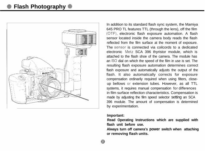
In addition to its standard flash sync system, the Mamiya645 PRO TL features TTL (through the lens), off the film(OTF), electronic flash exposure automation. A flashsensor located inside the camera body reads the flashreflected from the film surface at the moment of exposure.The .sensw is connected via coilcords to a dedicatedelectronic Metz SCA 396 thyristor module, which isattached to the flash shoe of the camera. The module hasan IS0 dial on which the speed of the film in use is set. Theresulting flash exposure automation determines correctflash exposure and automatically adjusts the output of theflash. It also automatically corrects for exposurecompensation ordinarily required when using filters, close-up bellows or extension tubes. However, as all TTLsystems, it requires manual compensation for differencesin film surface reflection characteristics. Compensation ismade by adjusting the film speed selector setting an SCA396 module. The amount of compensation is determinedby experimentation.
Important:Read Operating Instructions which are supplied withflash unit before use.Always turn off camera’s power switch when attachingor removing flash units.

Attaching Metz Flash Units
Metz flash 60CT-4/45CL-4Various optional accessories areneeded to attach different Metz FlashUnits to the Mamiya 645 TL
Metz shoe mount flash type Metz flash 50MZ-5This table shows accessories required with various Metz Flash Uunits
I
Metz Flash Units SCA396 adapter IF? SCA300 adapter 3 Bracket AD401 E’ Double shoe adapterAD402 0‘
--.-.-__~-_---.- -_----.__---. _--- _-.-.~---~_-~- -. _.-- -Shoe 60CT-4 Yes No N o N o
mount 50MZ-5 Yes Yes N o Yesflash 45CL-4 Yes No N o No
_---_---~.--40MZ-3 Yes N o N o No
“,“;$; 40MZ-2 Yes
flash 32MZ-332Z-2
Yes
Yes
N o N o N o
N o N o N o
m
TTL Flash Photography with Metz Flash Units
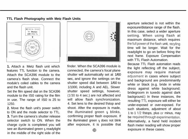
1. Attach a Metz flash unit whichfeatures TTL function to the camera.Attach the SCA396 module to thecamera’s flash shoe. Connect themodule’s coiled cables to the cameraand the flash unit.Set the film speed dial on the SCA396module to the IS0 rating for the filmin use. The range of IS0 is 25 to1250.2. Move the flash unit’s power switchto ON and the mode selector to TTL.3. Turn the camera’s shutter releaseselector switch to ON. When thecharge cycle is completed you willsee an illuminated green 5 readylightin the middle of the right side of the
00
finder. When the SCA396 module isconnected, the camera’s focal planeshutter will automatically set at 1/60sec, and ignore the settings on theshutter speed dial between 1/60 to1/1000, including A and AEL. Slowershutter speed settings, however,(1/30 to 4 sec.) are not affected andwill allow flash synchronization.4. Set lens to the desired f/stop andshoot. After the exposure is made,the illuminated green f blinks,confirming proper flash exposure. Ifthe illuminated green f does not blinkafter exposure, it is possible that
aperture selected is not within theexposure/distance range of the flash.In this case, select a wider aperturesetting. When using flash atmaximum distance, which requiresthe full power of theflash unit, recylingtime will be longer. Wait for thereadylight to go on before firing thenext frame. Exposure Compensationwith TTL Flash Automation.Because TTL Flash automation readsthe light reflecting off the subject,exposure may require manualadjusment in cases where subjectand background are predominantlywhite or black (e.g. bride in whitedress against white background;bridegroom in tuxedo against darkbackground.) In these instances, theresulting TrL exposure will either beunder-exposed or over-exposed. Forsuch situations, adjustment of about1 to 1 l/2 f/stops, plus or minus, maybe requiredthroughexperimentation.Alternatively, a hand held incidentflash meter reading will show properexposure in these cases.

Photography with Non-TTL Flash Units
<Caution>When using the Hot-shoe,be sure to put an appropriateSafety Cover over the X-syncterminal so that you won’treceive a high voltageelectric shock if the terminalis accidentally touched. (ASafety Cover is put on the X-sync terminal when thecamera leaves the factory.)
1. When using an electronic flash,plug the synchronization cord intothe Sync Teminal and set the ShutterSpeed Dial to 1/60 sec. or slower.
* The Mamiya 645 PRO has an X-sync terminal.
Attach a shoe-mount flash to the hot-shoe of the camera or the Left HandGrip GL401 (optional).
Flash synchronization Chart
* Do not use a flash unitspecifically dedicated for anothercamera. It may damage your 645PRO.* If you use a flash unit whoseflash duration is slower than 1/1000 sec., set the shutter speeddial to 1/30 sec. or slower.

@ Holding the Camera Steady and Securely h
Eye-level Operation Waist Level Operation
Hold the camera as shown in theillustration, with its base resting onyour left hand, the right hand sup-porting it from the side and top. Pressboth elbows against your body andactivate the shutter release with asmooth, steady pressure.
For waist level operation, it is deslr-able to have the Neck Strap attachedand adjusted for your size. Duringexposure keep it taut and press thecamera firmly against your body.
* Handholding the camera is eveneasier using the Power Drive GripWG401 or Left Hand Grip GL401.

Attaching and Removing the Neck Strap
Attaching the Strap to the Camera
1. While pushing down, pull out theNeck Strap Fastener @ of the attach-ing clip.
2. Place the hole of the strap fastener@I over the Neck Strap on the cam-era body as illustrated, and pull untilit clicks and locks into place.
With your fingers, pull the Neck Stra PFastener @I of the attaching clip up-ward and push part @I in the directionof the arrow. The strap can now beremoved.
* When attaching the Strap to theNeck Strap Lug on the side of thecamera with the Film AdvanceCrank, insert the neck strap fas-tener @ into the lower part of thedouble slot.

Basic Accessories
The AE Prism Finder FE401The Mamiya AE (Automatic Exposure) Prism FinderFE401 pentaprism guarantees a true, upright image andfeatures built-in electronic shutter control which ensuresaperture-priority, TTL automatic exposure metering whilein the A or AEL mode.
<3-Way Metering System>The FE401 comes with three metering modes: averagemetering (AV), spot metering (SP). and AV-SP meteringcapable of automatically selecting AV or SP according tosubject conditions.The LED display in the viewfinder indicates correctexposure.If you forget to extract the Dark Slide when the finder isbeing used with the 645 PRO TL, an LED will flash awarning.
Power Drive Grip WG401The motorized film transport mechanism is placed in anergonomically designed handgrip for speedy (2 f.p.s)and continuous shooting. Features include cable releasesocket, shutter release lock, multi-exposure switch, firstframe advance, battery check, and power connectorsocket for leaf shutter lenses. Uses 6 AA 1.5 V. batteries.
AE Reflex Finder FK402This aperture priority, Keplerian type, automatic (AE)reflex finder features TTL auto or manual exposure withcenter weighted averaging. It offers upright, eyelevelviewing with unreversed image.Exposure is indicated by red and green LEDs.. A built-inadjustable diopter eyepiece can be set from +/-5 forviewing convenience without eyeglasses.
Power Drive Grip WG 402This simplified, compact, lightweight grip uses one 6 V.lithium battery. It has a shutter release with lock andoffers single frame exposure mode.

/ Roll Film Holders I Interchangeable Lenses
120 Roll Film Holder HA401220 Roll Film Holder HE401135 Roll Film Holder HC401(with Panoramic Adapter)Polaroid Land Pack Film Holder HP401
Metz TTL Flash Unit
Shoe Mount60CT-4etc.
Flash Bracket AD401
Handle Mount40MZ-3etc.
Wide-angle Lenses : 35mm f/3.5N. 45mm f/2.8N,55mm f/2.8N
Telephoto Lenses : 150mm f/3.5N, A150mmf/2.8, 210mm f / 4 NULD300mmf/5.6N,A200mmf/2.8 APO, A300mmf/2.8APO, A500mmf/4.5 APO/500mm f/5.6
Standard Lenses :: 80mm f/1..9N, 80mm f/2.8N,Zoom Lenses : Zoom 55 - 110mm f/4.5N,
Zoom ULD105 1 210mmf/4.5
Special Effect Lenses : Fish-eye ULD24mmf/4 Shift50mm f/4. Macro 80mm f/4NMacro 120mm f/4M
Leaf Shutter Lenses : A55mmf/2.8N/L,A80mmf/2.8N/L, A150mm f/3.8N/L
Tele-Converter : 2 x Tele-Converter

System Chart
PnSm FiIlder FP40, AE Fl”&l FK402 wa,st Level Fin&i N

Trouble Shooting
* If the camera should fail to function properly,please check the following:
1. The Shutter Release Button cannot be depressed.
Push the Battery Check Button.If the lamp does not light, check:Is a Battery in the camera?If yes, is it correctly inserted? (Polarity)Is it dead?
If the lamp does light, check:Has the Film Holder Dark Slide been pulled?Is the Shutter Release Selector in the locked(Red Dot) position?If so, move it to the White Square and try again.Is the Shutter Speed Dial in the “A” or “AEL”position?If so, turn to other setting and try again.
2. The finder is black or very dark.Has the Lens Cap been removed?Is the Mirror-up Lever in the “M.UP” position?If so, turn the lever to the White Square.Is the “AM” setting on the lens at “M” (Depth ofField Preview)?If so, move it to “A”.
3. The Roll Film Holder cannot be removed from thecamera body.
Insert the Dark Slide.
4. The developed film has fewer exposures than Speci-fied.
Most likely the Start Mark had not been alignedproperly when the film was loaded. (See loading instructions page 20)
5. The Film Advance Crank continues to turn and doesnot stop.
Was the Roll Film Insert placed in the Roll FilmHolder?Was the empty fim spool left in the uppercompartment?

Mamiya 645 PRO TL Specifications
Camera type 6X4.5cm electronically focal-plane shutter SLR
Actual negative site 56mm X41.5mm
Film type 120 roll film (15 exposures)220 roll film (30 exposures)
Film loading
Standard lenses
Lens mount
Shutter
Shutter speed
Shutter release
Mirror
Viewfinder
Focusing screen
Field of view
Polaroid pack film (Polaroid 100, 600 series)135 roll film in film cartridge
Daylight loading - interchangeable film holders with film speed dial
Mamiya-Sekor C 80mm f/2.8NMamiya-Sekor C 80mm f/1.9N
M645 bayonet mount (applicable to all M645 lenses)
Moving coil, electronic controlled focal-plane shutter
(Manual) 4 sec. -1/1000 sec., B (T)(Auto) 8 sec. - 1/1000 sec. (When the AE Finder is used.)
Electromagnetic release.Selectable release lock or self-timer mode.
Instant return, front coated mirror, with mirror lock-up capability.
Interchangeable (Waist Level Finder N, Prism Finder FP401, AE Prism Finder FE401 and AE Finder FK402) .Standard: Rangefinder Spot/Microprism with Fresnel Lens,accessory screens available.(Same as the M645 Super)
94%


Things to Watch
* When using the AE Prism Finder FE401When using this finder it is imperative that the FilmSpeed Dial on the Roll Film Holder is properly set forthe IS0 number of the loaded film, as it interfaces withthis finder. If not done, wrong exposures may result.
* When the mirror is locked in the up position.The Focal Plane Shutter Curtain may be damaged ifthe camera faces strong light sources, especially thesun. Return mirror to normal position or use lens capto prevent such damage.

Common Sense Camera Care and Practice
Your Mamiya 645 PRO TL is a precision mechanical- + Do not store camera at temperatures exceeding 40%optical-electronic instrument, built for heavy and reliable (lOYF)and-lO’C(15”F)andprotect it against humidprofessional use. It will reward you with a long service life or sea air environment.if properly treated and maintained. Please observe these * Periodically exercise your camera and lenses bycommon sense rules: making blind exposures at various shutter speeds.
Read instructions before using camera. Also move the diaphragm ring and focusing mounts ofProtect camera against shocks and falls. Use all lenses repeatedly.neckstrap supplied with it, whenever possible.Protect camera against rain and moisture. If it getswet, wipe it with a soft, clean cloth.Do not touch lens or mirror surfaces. To remove dustuse air blower or lens tissue. To remove fingerprintsuse lens tissue and lens cleaning fluid if necessary.Do not touch gold plated contacts on camera body,lenses, rollfilm holders and AE Finders. If necessary.wipe them with a clean, dry cloth.Operate the film advance lever with even, measuredstrokes, to assure proper spacing.Always test your equipment before going on importantassignments.
Battery Advice :* The battery supplied with the camera by the factory
may have been subject to storage conditions whichhave reduced its service life. Check it before use andalways carry spare batteries.Be sure to wipe battery contacts before inserting it, inorder to insure proper contact.Be sure to observe proper polarity. (Match +pole ofbattery with +mark in battery chamber.)Battery life varies, depending on make, frequency ofuse, age, storage condition and ambient temperature.(Place battery in External Battery Case accessorywhich you wear inside your clothing, whenphotographing in cold climates)Always remove the battery when camera is not usedfor longer than a few weeks and store it in a cool, dryplace.
Storage ** When storing camera :
Turn shutter release selector dial to the red dot. (Offposition)Leave shutter and mirror in uncocked position.The same applies to leaf shutter lenses. @

Special Advice To Professional PhotographersYour Mamiya 645 PRO TL is designed for heavyprofessional use and will give you a long service life ifproperly maintained. Your camera and lenses havemany moving parts which require periodic lubrication. Itselectronic components, too, are subject to wear and tearand are affected by ambient conditions like dust, sand,sea air, heat and moisture.
If cameras had odometers like automobiles. it would beeasier to specify servicing schedules. May we suggestthat if you shoot thousands of film rolls per year, you sendyour equipment annually for servicing by the Mamiyadistributor in your country