Instructions for Use for Orthotists or Qualified/ EN NEURO ...
25
EN Download: www.fior-gentz.com Instructions for Use for Orthotists or Qualified/ NEURO HiSWING NEURO HiSWING
Transcript of Instructions for Use for Orthotists or Qualified/ EN NEURO ...
EN
Download: www.fior-gentz.com
Instructions for Use for Orthotists or Qualified/NEURO HiSWING
NEURO HiSWING

2
You can find these instructions for use in the download section on our website at www.fior-gentz.com/downloads.

3
Content Page
EN
Instructions for Use for Orthotists or Qualified/Trained Experts System Ankle Joint 51. Information 52. Safety Instructions 5
2.1 Classification of the Safety Instructions 52.2 All Instructions for a Safe Handling of the System Ankle Joint 5
3. Use 83.1 Intended Use 83.2 Indication 83.3 Qualification 83.4 Application 83.5 Combination Possibilities with Other System Joints 8
4. Joint Function 95. Scope of Delivery 96. Load Capacity 107. Tools for Assembling the System Joint 108. Disassembly and Assembly Instructions 10
8.1 Demounting the Functional Unit 118.2 Mounting the Functional Unit 118.3 Mounting the System Stirrup 128.4 Checking the System Joint's Free Movement 128.5 Mounting the Spring Unit 128.6 Checking the Lever 138.7 Securing the Screws 13
9. Adjustment Options on the Orthosis 149.1 Initial Setting of the Orthosis Alignment and Positioning of the Spirit Level 149.2 Adjusting the Orthosis Alignment 149.3 Increasing the Range of Motion 159.4 Exchanging the Spring Unit 159.5 Reading the Joint Angles 15
10. Notes on the Production of the Orthosis 1510.1 Mounting to the System Side Bar/System Anchor 1510.2 Grinding the Orthosis Parts 1610.3 Mounting the Spirit Level 16
11. Converting the System Ankle Joint 1611.1 Converting Options with plug + go modularity 1611.2 Conversion 16

4
12. Maintenance 1712.1 Documentation of Maintenance in the Orthosis Service Passport 1812.2 Maintenance of the Disc Springs 1812.3 Replacing the Sliding Washers 1812.4 Dirt Removal 18
13. Period of Use 1914. Storage 1915. Spare Parts 20
15.1 Exploded View Drawing NEURO HiSWING 2015.2 Spare Parts for the NEURO HiSWING System Ankle Joint 2115.3 Spring Units 2115.4 Sliding Washers 22
16. Disposal 2317. Signs and Symbols 2318. CE Conformity 2319. Legal Information 2320. Information for the Treatment Documentation 2421. Handing Over the Orthosis 25

5
Instructions for Use for Orthotists or Qualified/Trained Experts System Ankle Joint1. Information
These instructions for use are addressed to orthotists or qualified/trained experts and do not contain any notes about dangers which are obvious to them. To achieve maximum safety, please instruct the patient and/or care team in the use and maintenance of the product.
2. Safety Instructions
2.1 Classification of the Safety Instructions
DANGER Important information about a possible dangerous situation which, if not avoided, leads to death or irreversible injuries.
WARNING Important information about a possible dangerous situation which, if not avoided, leads to reversible injuries that need medical treatment.
CAUTION Important information about a possible dangerous situation which, if not avoided, leads to light injuries that do not need medical treatment.
NOTICEImportant information about a possible situation which, if not avoided, leads to damage of the product.
All serious incidents according to Regulation (EU) 2017/745 which are related to the product have to be reported to the manufacturer and to the competent authority of the member state in which the orthotist or qualified/trained expert and/or the patient is established.
2.2 All Instructions for a Safe Handling of the System Ankle Joint
DANGERPotential Traffic Accident Due to Limited Driving AbilityAdvise the patient to gather information about all safety and security issues before driving a motor vehicle with orthosis. The patient should be able to drive a motor vehicle safely.
WARNINGJeopardising the Therapy Goal by Not Providing the Necessary Free MovementCheck if the system joint moves freely in order to avoid restrictions of the joint function. Use suitable sliding washers according to the information in these instructions for use.
WARNINGRisk of Falling Due to Permanent Higher LoadIf patient data has changed (e.g. due to weight gain, growth or increased activity), recalculate the expected load on the system joint, plan the treatment again and, if necessary, produce a new orthosis.

6
WARNINGRisk of Falling Due to Improper ProcessingProcess the system joint according to the information in these instructions for use. Deviating processing and modifications of the system joint require the written consent of the manufacturer.
WARNINGRisk of Falling Due to Wrong Heel HeightDetermine with the patient a maximum heel height of the shoes to be worn with the orthosis.
WARNINGRisk of Falling Due to Improper HandlingInform the patient about the correct use of the system joint and potential dangers especially with regards to:- moisture and water as well as- excessive mechanical stress (e.g. due to sports, increased activity or weight gain).
WARNINGRisk of Falling Due to Improper Handling of the LeverUse the lever as described in these instructions for use. Inform the patient about the proper handling of the lever, especially with regards to: - pushing the lever fully upwards before adjusting the ankle joint angle;- changing the ankle joint angle with minimal effort;- not putting any weight on the orthosis when the lever is pushed upwards (e.g. when standing, walking,
running or cycling);- securing the system joint before putting weight on the orthosis by pushing the lever completely down-
wards so that it does not protrude.
WARNINGRisk of Falling Due to Loosely Attached Functional UnitMount the functional unit on the system joint according to the assembly instructions in these instructions for use. Secure the screws with the specified torque and the corresponding adhesive and make sure that no sliding washers are damaged in the process.
WARNINGRisk of Falling Due to Incorrectly Mounted Spirit LevelMount the spirit level on the orthosis according to the assembly instructions in these instructions for use. Please also refer to the online tutorials on our website or contact Technical Support.
WARNINGRisk of Falling Due to Incorrectly Selected System ComponentsMake sure that the system joint and the system components are not overloaded and are functionally adapted to the requirements and needs of the patient in order to avoid joint dysfunction.

7
WARNINGRisk of Falling Due to Use of the Orthosis without ShoeIf the patient wants to wear the orthosis without a shoe, attach a fixation that holds the foot piece against the foot. Additionally, place a slip-resistant rubber sole under the sole of the foot piece.
WARNINGDamage to the Anatomical Joint Due to Incorrect Position of the Joint’s Mechanical Pivot PointDetermine the joint’s mechanical pivot points correctly in order to avoid a permanent incorrect load on the anatomical joint. Please refer to the online tutorials on our website or contact Technical Support.
WARNINGDamage to the System Joint Due to Improper Handling of the Functional UnitDo not open the hydraulics of the functional unit. Do not loosen the screws of the hydraulics as this will cause damage to the hydraulics.
NOTICEDamage to the System Joint Due to Improper Handling of the LeverUse the lever as described in these instructions for use. Inform the patient about the proper handling of the lever, especially with regards to not putting weight on the orthosis when the lever is pushed upwards as this can damage the hydraulics of the system joint.
NOTICELimitation of the Joint Function Due to Improper ProcessingErrors in processing can impair the joint function. Pay particular attention to:- correctly connect the system side bar/system anchor with the system case in accordance with the
production technique;- grease the joint components only slightly and- adhere to the maintenance intervals.
NOTICELimitation of the Joint Function Due to Improper Dirt RemovalInform the patient on how to properly remove dirt from the orthosis and the system joint.
NOTICELimitation of the Joint Function Due to Lack of MaintenanceRespect the specified maintenance intervals in order to avoid joint dysfunction. Inform the patient about the maintenance appointments to be respected. Enter the next maintenance appointment in the orthosis service passport of the patient.

8
3. Use
3.1 Intended Use
The NEURO HiSWING system ankle joint is exclusively for use for orthotic fittings of the lower extremity. The system joint provides motion control and is only allowed to be used for producing an AFO or a KAFO. Every system joint influences the orthosis’ function and thus also the function of the leg. The orthotist or qualified/trained expert must determine whether the type of orthotic treatment and the patient’s individual physical abilities guarantee the safe driving of a motor vehicle. The system joint may only be used for one fitting and must not be reused.
3.2 Indication
The indication for the treatment with an orthosis for the lower extremity is a pathological gait. This can be caused, for example, by central, peripheral, spinal or neuromuscular paralyses, structurally conditioned defor-mities/malfunctions or surgery.
The physical conditions of the patient, such as muscle strength or activity level are crucial for the orthotic treatment. An evaluation regarding the safe handling of the orthosis by the patient must be carried out.
3.3 Qualification
The system joint must only be handled by an orthotist or a qualified/trained expert.
3.4 Application
All FIOR & GENTZ system joints were developed for everyday life activities such as standing and walking. Ex-treme loads connected to activities like running, climbing and parachuting are excluded. The system joint can be used at temperatures of up to +60° C.
3.5 Combination Possibilities with Other System Joints
The NEURO HiSWING system ankle joint can be combined with other system joints from our product range, with the exception of the NEURO MATIC system knee joint. The NEURO CLASSIC system ankle joint can be used as supporting joint.
We recommend that you use the Orthosis Configurator when selecting all system components for your orthosis and follow the recommendations of the configuration result.
All system ankle joints can also be used for the prosthetic treatment of patients with partial foot amputations. For this purpose, the orthosis produced for the patient by the orthotist or qualified/trained expert (custom-ma-de product) is combined with a foot prosthesis. Further information can be found in the Guide to Partial Foot Amputations.
9
4. Joint Function
The basic function of all system ankle joints is to provide motion control. The system ankle joint provides the additional functions listed below:
System Component Function
spring units
dorsal (posterior spring unit): - limitation of the maximum range of motion in plantar flexion- integrated dorsiflexion assist- controlled lowering of the foot during loading response
ventral (anterior spring unit):- limitation of the maximum range of motion in dorsiflexion- increased energy return during heel lift supporting push off
dorsal and ventral:- dynamically bringing the patient into an upright position as well as stabilising the
patient when walking and standing by balancing the body
lever- adjustment of the orthosis alignment by the orthotist or qualified/trained expert- modification of the ankle joint angle by the patient, e.g. when the terrain changes- increase of the range of motion by 34°
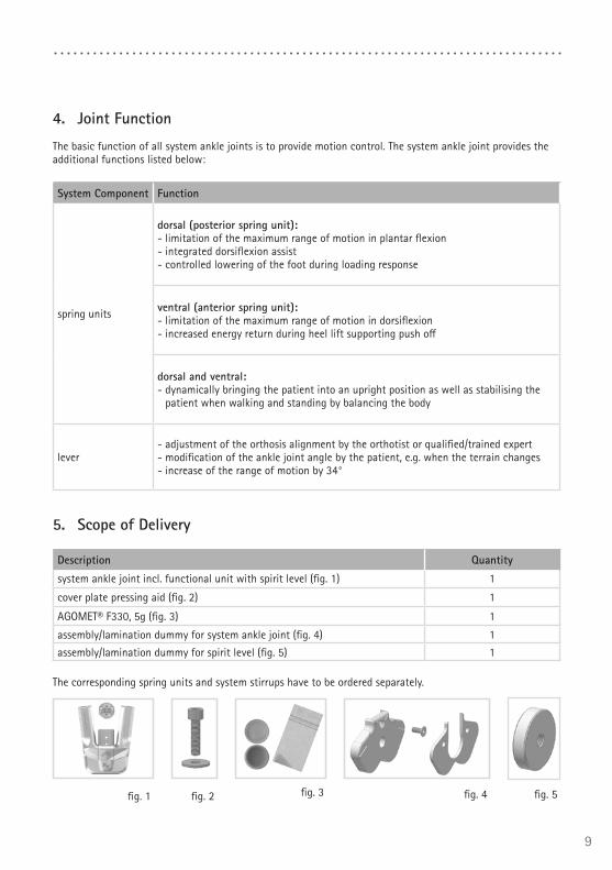
5. Scope of Delivery
Description Quantity
system ankle joint incl. functional unit with spirit level (fig. 1) 1
cover plate pressing aid (fig. 2) 1
AGOMET® F330, 5g (fig. 3) 1
assembly/lamination dummy for system ankle joint (fig. 4) 1
assembly/lamination dummy for spirit level (fig. 5) 1
The corresponding spring units and system stirrups have to be ordered separately.
fig. 1 fig. 2 fig. 3 fig. 4 fig. 5

10
6. Load Capacity
The load capacity results from the relevant patient data and the choice of shoes. When selecting the system joint, the maximum heel height of the shoes that the patient wants to wear with the orthosis must be taken into account after consultation with the patient. The load capacity can be determined by using the Orthosis Configurator. We recommend that you use the system components determined by the Orthosis Configurator when producing an orthosis and mind the recommended production technique.
7. Tools for Assembling the System Joint
Tools for System Joint Screws System Width20mm
T20 hexalobular screwdriver/bit x
T8 hexalobular screwdriver/bit x
torque screwdriver 1–6Nm x
hexagonal screwdriver with spherical head, 5 x 100mm x
pliers x
Tools for Spirit Level System Width20mm
T6 hexalobular screwdriver/bit x
Tools for Pressing Screw System Width20mm
T25 hexalobular screwdriver/bit x
8. Disassembly and Assembly Instructions
The system joint is delivered fully assembled. All functions are checked beforehand. In order to mount the system joint on the orthosis and for maintenance work, you must first remove the functional unit from the system joint. To ensure optimal function after assembly, follow the assembly instructions below. Secure all screws with the torque specified in para graph 8.7.
The hydraulics of the functional unit must not be opened. Refer to the exploded view drawings (figs. 35–37) to see which system components of the system joint may be demounted. The screws of the hydraulics marked in fig. 6 must not be loosened.
fig. 6
x
x x

11
8.1 Demounting the Functional Unit
1 Push the lever on the front of the functional unit upwards.2 Unscrew both countersunk flat head screws.3 Place the washer on the functional unit and screw the pressing screw into the
thread of the first screw (S1). The pressing screw must not be screwed in comple-tely (fig. 7).
4 Push the joint’s upper part and the functional unit apart by exerting force on them as illustrated (arrows in fig. 7). This can be achieved by using a vice or by controlled knocks, e.g. with a soft-face hammer.
5 Remove pressing screw and washer.
8.2 Mounting the Functional Unit
1 Clean the thread of the bearing nut and of the joint’s upper part as well as the bores of the functional unit with LOCTITE® 7063 Super Clean, if necessary. Allow the threads to air-dry for 10 minutes.
2 Apply spray adhesive on one side of a sliding washer and adhere it to the functio-nal unit (fig. 8).
3 Grease the other side slightly with orthosis joint grease.4 Grease the lateral contact surfaces on the functional unit to the joint’s upper part
with orthosis joint grease.5 Mount the functional unit by pressing it with the pressing screw and the washer
(fig. 9).6 Remove pressing screw and washer.7 Screw in the first countersunk flat head screw (S1; fig. 10).8 Make sure that there is no opening left between the functional unit and the joint's
upper part (fig. 11).fig. 11
fig. 9
fig. 7
fig. 8
Make sure not to damage the sliding washer during the assembly. Jammed sliding washer particles can cause lateral play in the system joint.
fig. 10
S1

12
8.3 Mounting the System Stirrup
1 Grease the sliding surfaces of the bearing nut as well as the contact surfaces of the system stirrup between system stirrup and spring units with orthosis joint grease.
2 Grease the second sliding washer slightly on both sides and place it on the system stirrup so that there is one sliding washer on each side (fig. 12).
3 Slide the system stirrup from below between the functional unit and the joint's upper part. Make sure that the sliding washer remains in the correct position.
4 Put the bearing nut into the joint's upper part. The bearing nut must be fully inserted in the opening (figs. 13–14).
5 Screw in the second countersunk flat head screw (axle screw, S2; fig. 15).
8.4 Checking the System Joint's Free Movement
Check if the system joint moves freely. If the system joint runs with lateral play, mount the next thicker sliding washer. If it does not move freely (it is jammed), mount the next thinner sliding washer.
8.5 Mounting the Spring Unit
1 Loosen the screws on the back of the functional unit and remove both spring unit covers (fig. 16).
2 Loosen the screws on top of the spring ducts and re-move the adjusting screw covers (fig. 17). The adjusting screws (2) are now visible.
3 Unscrew the adjusting screws slightly and push the lever (1) on the front of the functional unit upwards.
4 Assemble the O-ring dampers (4) and the sliding bushings (5) with the plungers (3; fig. 18).
5 Put the pressure springs (6) on them.6 Insert the spring units (7) including the plungers (3) and the assem-
bled system components (4, 5 ,6) into the spring ducts (fig. 19).7 Screw the adjusting screws back in. Make sure that there is no lateral
play and no play around the axis. The adjusting screws should come into contact with the spring units without exerting pressure on them.
S1
S2
fig. 15
fig. 16 fig. 17
fig. 13
fig. 12
fig. 18
7
3654
fig. 14
2
1

13
8 Push the lever downwards.9 Replace the spring unit covers on the back of the functional unit and the
adjusting screw covers on the spring ducts.
8.6 Checking the Lever
After mounting the spring units, check the function of the lever.
1 Push the lever upwards.2 Move the system joint in ap direction and check if the ankle joint angle can be changed.3 Push the lever downwards and check if the new ankle joint angle is secured and unchanged.
8.7 Securing the Screws
The screws are secured after the orthosis has been produced and tried on and before it is handed over to the patient.
1 Secure the screws for the functional unit (fig. 15) with the torque corresponding to the system width and LOCTITE® 243 medium strength.
2 Let the adhesive harden (final strength after approx. 24 hours).
Screws for Functional UnitSystem Width
20mm
pressing screw of the cover plate pressing aid 6Nmcountersunk flat head screw with hexalobular socket (S1, fig. 15) 6Nm
countersunk flat head screw with hexalobular socket (axle screw, S2, fig. 15) 4Nm
Push the lever upwards and check the hydraulics after inserting the spring units into the system joint and screwing back in the adjusting screws. If the hydraulics are disturbed (lack of movement in the hydrau-lics), loosen the adjusting screws slightly.
The screws of the functional unit are not secured with the necessary torque at delivery. You can also find information on the torque in the openings of the functional unit.
fig. 19

14
9. Adjustment Options on the Orthosis
The orthosis with adjustable system ankle joints can be individually adapted to the pathological gait. The adjustments described in the paragraphs 9.1 to 9.4 do not influence each other and can be changed separately.
9.1 Initial Setting of the Orthosis Alignment and Positioning of the Spirit Level
Using the lever on the functional unit, the ankle joint angle can be infinitely adjusted in both directions by up to 17°. To do so, proceed as follows:
1 Place the orthosis in the shoe.2 Push the lever upwards (fig. 20) and bring the orthosis in the desired position
(fig. 21).3 Secure the system joint by pushing the lever downwards (fig. 22).4 Align the spirit level using a hexalobular screwdriver. The air bubble must be
aligned centrally (fig. 23).
9.2 Adjusting the Orthosis Alignment
The alignment of the orthosis can be adjusted if the patient's gait has changed. To do so, proceed as follows:
1 Push the lever upwards (fig. 20) and bring the orthosis on the patient’s leg in the desired position (fig. 21).
2 Secure the system joint by pushing the lever downwards (fig. 22).3 Realign the spirit level as described in paragraph 9.1.
Mind the correct adjustment of the dorsiflexion stop when moun-ting the system ankle joint. It is decisive for the entire alignment of the orthosis.
Make sure that the lever is pushed downwards completely. If it protrudes slightly, the orthosis does not provide the necessary security. Furthermore, this can cause damage to the hydraulics of the system joint.
fig. 20
fig. 21
fig. 22
fig. 23
The spirit level (see paragraph 10.3) is positioned so that it indicates the correct orthosis alignment and can later be used by the orthotist or a qualified/trained expert and the patient as guidance.

15
9.3 Increasing the Range of Motion
The range of motion of the system joint can be increased by 34° by pushing the lever upwards. Note that the spring units are not active in this setting.
9.4 Exchanging the Spring Unit
The spring force can be changed with spring units (2) in different strengths (fig. 24). Insert a spring unit into the spring duct that corresponds with the required spring force. There are five spring units with spring forces ranging from normal to extra strong (fig. 25). Note that the spring unit determines the maximum possible range of motion of the secured system joint.
In order to exchange the spring unit, the adjusting screw (1) must be loosened first (fig. 24). After inserting the new spring unit, the adjusting screw must be screwed in again until the spring unit is mounted without play.
9.5 Reading the Joint Angles
There are markings (fig. 26) on all system joints and system stirrups which indicate the angle of the system components to each other. This allows you to check the individual normal posture (the orthosis' basic alignment), record the joint angle and compare later deviations.
The distances between the degree markings can be seen in the follow-ing table.
Degree Marking
System Width 20mm
Degree 2°
10. Notes on the Production of the Orthosis
10.1 Mounting to the System Side Bar/System Anchor
The system side bar/system anchor must be adhered and screwed or sewed together with the joint according to the recommended production technique (figs. 27–29). You will find more detailed information in the Instructions for Use for Orthotists or Qualified/Trained Experts System Side Bars and System Anchors.
1
22
fig. 24
fig. 26
fig. 25
15° 15° 10° 10° 5°
This setting is only suitable for sitting and for putting on and taking off the orthosis and must not be used when standing or walking. The orthosis does not provide the patient with the necessary secu-rity as its function is disabled in this setting. Furthermore, this can cause damage to the hydraulics of the system joint.
fig. 27 fig. 28 fig. 29

16
10.2 Grinding the Orthosis Parts
After tempering the orthosis parts, grind the laminate edges. Make sure not to grind the lateral surfaces of the joint’s upper part. This can damage the fit between the joint’s upper part and the cover plate, which can lead to mechanical noises and to the breakage of the feather keys with pin. Make sure that the lower edges of the functional unit do not come into contact with the laminate of the foot piece when the lever is pushed upwards, both in full dorsiflexion and full plantar flexion, so that the patient can use the full range of motion.
You will find information on the production techniques in the section “Online Tutorials” on our website www.fior-gentz.com.
10.3 Mounting the Spirit Level
Mount the the spirit level laterally on the tibial shell. Please also refer the online tutorial on our website or contact Technical Support.
11. Converting the System Ankle Joint
11.1 Converting Options with plug + go modularity
The NEURO HiSWING is designed with plug + go modularity. All system ankle joints with plug + go modu-larity have identical system stirrups, joint's upper parts and assembly/lamination dummies and can be easily converted among themselves. All functional differences are integrated in the functional unit. The following system ankle joints are provided with plug + go modularity:
- NEURO VARIO-CLASSIC 2 - NEURO VARIO 2 - NEURO VARIO-SPRING 2 - NEURO VARIO-SWING - NEURO SWING - NEURO SWING 2 - NEURO HiSWING
11.2 Conversion
1 Demount the functional unit.2 Mount the functional unit of the desired system joint in the correct system
width (fig. 30).
When demounting and mounting the functional unit, follow the steps in paragraph 8 and 10.2.
fig. 30

17
12. Maintenance
Check the system joint for wear and functionality every 6 months. In particular, check the system components listed in the following table for the possible problems described and, if necessary, take the appropriate mea-sures. Also check the functionality after every maintenance carried out. It must be possible to move the system joint without problems or unusual noises. Make sure that there is no lateral play and no play around the axis.
System Component Potential Problem Measure
Inspection/ Replacement, if necessary
Latest Replacement
functional unit wear replacing functional unit every 6 months every 36 monthscountersunk flat head screw with hexalobular socket
wear replacing countersunk flat head screw every 6 months every 24 months
spring unit
wear or reduced spring force/range of motion replacing spring unit every 6 months every 24 months
breakage of disc springs/pressure spring replacing spring unit every 6 months every 24 months
radial move of disc springs (fig. 32)
realigning disc springs with pliers every 6 months every 24 months
squeaking of pressure spring
greasing pressure spring with orthosis joint grease every 6 months every 24 months
pressure spring wear or reduced spring force replacing pressure spring every 6 months every 24 months
sliding bushing wear replacing sliding bushing every 6 months every 24 months
O-ring damper wear replacing O-ring damper every 6 months every 24 months
plunger wear replacing plunger every 6 months every 24 months
bearing nut wear replacing bearing nut every 6 months every 24 months
sliding washer wear replacing sliding washer, see paragraph 13.3 every 6 months every 24 months
system stirrup wear or breakage replacing system stirrup every 6 months every 48 months
system side bar wear or breakage replacing system side bar every 6 months not applicable
system anchors wear or breakage replacing system anchor every 6 months not applicable
Clean the thread of the bearing nut and of the joint’s upper part as well as the bores of the functional unit with LOCTITE® 7063 Super Clean at every maintenance. Allow the threads to air-dry for 10 minutes.
Secure the screws for the functional unit with the corresponding torque and LOCTITE® 243 medium strength during every maintenance (see paragraph 8.7). Remove all adhesive residues first.
The hydraulics of the functional unit must not be opened. Refer to the exploded view drawings (figs. 35–37) to see which system components of the system joint may be demounted.

18
12.1 Documentation of Maintenance in the Orthosis Service Passport
The patient receives an orthosis service passport from their orthotist or a qualified/trained expert when the orthosis is handed over. The orthosis must be checked every 6 months in order to maintain its function and to ensure the safety of the patient. The maintenance appoint-ments are noted and confirmed in the orthosis service passport.
12.2 Maintenance of the Disc Springs
Check the disc springs particularly carefully during maintenance. If necessary, realign the disc springs to increase the useful life of the spring unit. If necessary, replace the spring unit to maintain the functionality of the system joint.
12.3 Replacing the Sliding Washers
Sliding washers are available in different thicknesses (e.g. GS1407-040 is 0.40mm thick). Each thickness has a different marking (fig. 34). You will find the article numbers of the premounted sliding washers on the back page of these instructions for use.
12.4 Dirt Removal
Dirt must be removed from the system joint when necessary and during regular maintenance. For this purpose, disassemble the system joint and clean the soiled system components with a dry cloth.
fig. 31
fig. 32 fig. 33
0.40mm 0.45mm 0.50mm 0.55mm 0.60mm
fig. 34

19
13. Period of Use
To guarantee a safe use and complete functionality as well as an unlimited period of use of the system joints, you must adhere to the following conditions:
1 Adhere to the specified maintenance intervals without interruption and document each maintenance (see paragraph 12).
2 Adhere to the determined maintenance conditions (see paragraph 12).3 Check the wear parts, as required, and replace them in the defined intervals (see paragraph 12).4 Check the adjustment of the system joint during maintenance and correct it, if necessary (see para-
graph 12).5 Check the functionality of the system joint during maintenance (see paragraph 12).6 The maximum load determined during the planning of the custom-made product shall not be exceeded
by changes in the patient data (e.g. due to weight gain, growth or increased activity). If the determined maximum load on the system joint is exceeded, the system joint must no longer be used. When planning the custom-made product, expected changes in patient data need to be taken into account.
7 The period of use of the system joints ends with the period of use of the custom-made product (orthosis).8 The multiple use of the system joint in another custom-made product is not allowed (see paragraph 19).
14. Storage
It is recommended to store the system joint in its original packaging until the custom-made product is pro-duced.

20
15. Spare Parts
15.1 Exploded View Drawing NEURO HiSWING
fig. 35
4
5
6
11a
8
7
9
10
12
413
3
6
6
12
11
fig. 36 fig. 37
15
15a
14

21
15.2 Spare Parts for the NEURO HiSWING System Ankle Joint
Item
Article Number for System Width
20mm Description
1 SB1069-L0960 bearing nut
2-3 SF0315-P/TI upper part with feather keys, straight, titanium
2-3 SF0335-P/TI upper part with feather keys, bent inwards, titanium
2-3 SF0335-8P/TI upper part with feather keys, bent outwards, titanium
3 SF0395-01 feather key with pin
4 GS2611-* sliding washer*
5 SH0765-2/L spring unit cover, left lateral or right medial
5 SH0765-2/R spring unit cover, left medial or right lateral
6 SC1403-L08/1 countersunk flat head screw with hexalobular socket
7 SH0493-01 plunger
8 VE3771-012/26 O-ring damper
9 GS1108-500 sliding bushing
10 FE1027-01 pressure spring
11 SH7805 spirit level
11a SC9403-L05 securing pin
12 SH0765-3/L adjusting screw cover, left lateral or right medial
12 SH0765-3/R adjusting screw cover, left medial or right lateral
13 SC1405-L14 countersunk flat head screw with hexalobular socket
14 SC1406-L14 countersunk flat head screw with hexalobular socket (axle screw)
5–14 SH7975-AL functional unit plug + go modularity
All system stirrups of the NEURO HiSWING system ankle joint are delivered with an integrated sliding bushing.
15.3 Spring Units
Item
Article Number for System Width
20mm Description
15 SH5805-15/18 spring unit, blue, normal, max. 15° range of motion
15 SH5805-15/25 spring unit, green, medium, max. 15° range of motion
15 SH5805-10/40 spring unit, white, strong, max. 10° range of motion
15 SH5805-10/60 spring unit, yellow, very strong, max. 10° range of motion
15 SH5805-05/99 spring unit, red, extra strong, max. 5° range of motion
15a VE3771-11/10 O-ring for securing the spring unit

22
15.4 Sliding Washers
* Sliding Washers
Article Number for System Width
20mm
Ø = 26mm
GS2611-040
GS2611-045
GS2611-055
GS2611-050
GS2611-060

23
16. Disposal
Dispose of the system joint and its individual parts properly. The product must not be dis-posed of with the residual waste (fig. 38). Please comply with the applicable national laws and local regulations for the proper recycling of recyclable materials.
17. Signs and Symbols
Symbols on the Packaging
medical device
18. CE Conformity
We declare that our medical devices as well as our accessories for medical devices are in conformity with the requirements of Regulation (EU) 2017/745. Therefore, the FIOR & GENTZ products bear the CE marking.
19. Legal Information
With the purchase of this product, our General Terms and Conditions of Business Transactions, Sales, Delivery and Payment will apply. The warranty expires, for example, if the product is mounted several times. Please note that the product is not supposed to be combined with other components or materials than with those recom-mended according to the configuration result from the FIOR & GENTZ Orthosis Configurator. The combination of the product with products from other manufacturers is not permitted.
The information in these instructions for use is valid at the date of printing. The contained product information serve as guidelines. Subject to technical modifications.
All rights, particularly the distribution, copy and translation of these unstructions for use or any part of them, in paper or as electronic document, must be authorised in writing by FIOR & GENTZ Gesellschaft für Ent-wicklung und Vertrieb von orthopädietechnischen Systemen mbH. Reprints, copies and any other electronic reproduction, even partial, must be authorised in writing by FIOR & GENTZ Gesellschaft für Entwicklung und Vertrieb von orthopädietechnischen Systemen mbH.
For proper disposal, it is necessary to demount the system joint from the orthosis.fig. 38

24
20. Information for the Treatment DocumentationAdd these instructions for use to your treatment documentation!
Patient Data
Name
Adress
Postcode,City
Home Telephone
Telephone at Work
Insurance
Insurance No.
Attending Physician
Diagnosis

Gesellschaft für Entwicklung und Vertrieb von orthopädietechnischen Systemen mbH
Dorette-von-Stern-Straße 5 21337 Lüneburg (Germany)
[email protected] www.fior-gentz.com
+49 4131 24445-0+49 4131 24445-57
ZERT
IFIZIERT CERTIFIED
Reg.-Nr.: Q1 0107
014
•
• •DIN EN ISO
9001
ZERT
IFIZIERT CERTIFIED
Reg.-Nr.: MQ1 0107
014
•
• •DIN EN ISO
13485
21. Handing Over the Orthosis
The orthotist or qualified/trained expert has also handed over the instructions for use for patients as well as the orthosis service passport to you as a patient, parent or care team. By means of these instructions for use, the functions and handling of the orthosis were explained to you in detail. You will find the next maintenance appointment in the orthosis service passport. Bring the orthosis service passport with you to every maintenance appointment.
Place, Date
PB15
00-D
E-20
21-0
5
Heel Height Considered when Selec-ting the System Joint:
____________ mm
The patient was informed about the maximum heel height to be used.
Leg Side
leftright
Mounted Sliding Washer
1. GS ___________ - ________
2. GS ___________ - ________
Signature Patient


![Neuro Assessment for Scalp the Non-Neuro Nurse … · Neuro Assessment for the Non-Neuro Nurse Terry M. Foster, RN, ... Microsoft PowerPoint - Neuro Grand Forks ND [Read-Only] Author:](https://static.fdocuments.in/doc/165x107/5b88746b7f8b9a301e8d8c76/neuro-assessment-for-scalp-the-non-neuro-nurse-neuro-assessment-for-the-non-neuro.jpg)