
Instructions For eTakeoff Structural Steel Takeoff Tools ... · Instructions For eTakeoff ......
56
Instructions For eTakeoff Structural Steel Takeoff Tools Version 1.3.0 Documentation Of The Custom Takeoff Tools, Traces, Measurement List Creation and Modification Procedure This document provides instructions, screen shots and links to videos to assist in the learning and use of eTakeoff Advanced, the eTakeoff Extension Add-in and the creation and structure of the custom Measurement List for text identified quantity takeoffs and transfer to Excel. This document is for Structural Steel. 2016 Chad Langhans Copyright 2013-2016 CSP Construction Technology 7/21/2016
-
Upload
nguyentuyen -
Category
Documents
-
view
221 -
download
0
Transcript of Instructions For eTakeoff Structural Steel Takeoff Tools ... · Instructions For eTakeoff ......
Page 1 of 56
You have been shipped this file as part of this email:
Save it to a folder related to eTakeoff Projects.
Open eTakeoff and under “Options” select “Import Standards”:
In the window that opens, find and select the AsphaltStd.tsx file:
Then, left click “Open”.
In the window that opens next, left click “Standards Database”. After you click the folder, it will have a blue checkmark on it and the Extensions, Layers, & Traces folder icons as well.
Left click “Import”. The asphalt extension, its trace, and the layer are saved to your eTakeoff system.
Close and then re open eTakeoff.
Instructions For eTakeoff Structural Steel Takeoff Tools
Version 1.3.0 Documentation Of The Custom Takeoff Tools, Traces, Measurement List Creation and Modification Procedure This document provides instructions, screen shots and links to videos to assist in the learning and use of eTakeoff Advanced, the eTakeoff Extension Add-in and the creation and structure of the custom Measurement List for text identified quantity takeoffs and transfer to Excel. This document is for Structural Steel.
2016
Chad Langhans Copyright 2013-2016 CSP Construction Technology
7/21/2016
Page 2 of 56
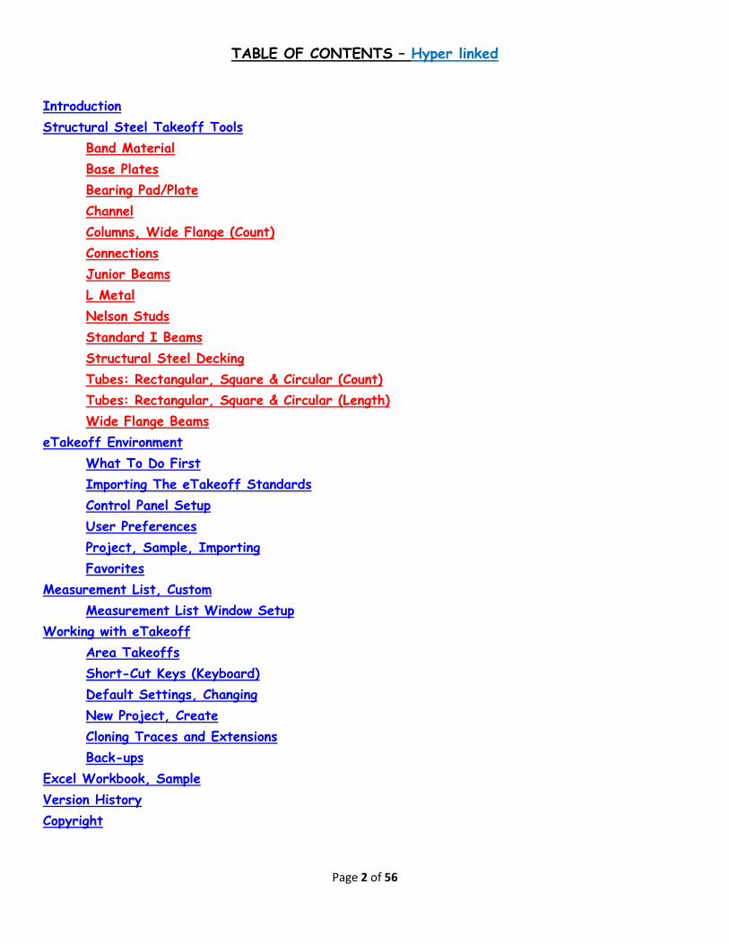
TABLE OF CONTENTS – Hyper linked
Introduction Structural Steel Takeoff Tools
Band Material Base Plates
Bearing Pad/Plate Channel Columns, Wide Flange (Count) Connections Junior Beams L Metal Nelson Studs Standard I Beams Structural Steel Decking Tubes: Rectangular, Square & Circular (Count) Tubes: Rectangular, Square & Circular (Length) Wide Flange Beams eTakeoff Environment
What To Do First Importing The eTakeoff Standards Control Panel Setup User Preferences Project, Sample, Importing Favorites
Measurement List, Custom Measurement List Window Setup
Working with eTakeoff Area Takeoffs Short-Cut Keys (Keyboard) Default Settings, Changing New Project, Create Cloning Traces and Extensions
Back-ups Excel Workbook, Sample
Version History Copyright

Page 3 of 56
INTRODUCTION TO THE eTAKEOFF CUSTOM TOOL SET:
With the release of eTakeoff Version 3.02-61 in June of 2013, it became possible to create a takeoff environment in which the output as displayed in the eTakeoff Measurement List is not restricted to 4 data outputs. Previously in the year, with 3.02-33, it became possible to include text in the assemblies/extensions that could be built by those with eTakeoff Premier or eTakeoff Advanced with the Extension Add-In. Coupling both these capabilities together means for a user of eTakeoff, with the purchase of Advanced and the Extension Add-In, it is now possible to build extensions/assemblies that are text friendly, meaningful for information resulting from the structure of the assemblies and extremely user friendly; and the information available from the assembly calculations is not restricted to 4 columns – the columns are actually unlimited in quantity.
I have built several systems for specific trades that use as many as 27 custom columns, populated with calculation data from the assemblies, that transfer by drag and drop into Excel with a couple of key strokes.
This Structural Steel takeoff system is just such a system. You can view a video of the tools I first built (Custom Takeoff Tools), using these capabilities, here.
Page 4 of 56
eTAKEOFF STRUCTURAL STEEL TAKEOFF TOOLS:
There are fourteen groups of tools as part of this system. For the most part, each of the groups is separated into Length and Count trace types. In eTakeoff, a trace is a measuring tool that leaves a “Trace” on the screen as it performs its function. Standard ASTM values have been entered for each type of piece. You can change the values entered there because it is a text box.
The weights are always output in tons, never pounds. If you wish to verify a weight multiply its weight given in the “PcWt (Ton)” by 2000. The weights for those pieces that have a weight per foot (i.e.: W18x24) are determined by using the weight included with the description. Weights for other pieces are determined by a value for mild steel on a square foot and 1/16” thickness. You can see how that value is applied in the various extension/assemblies and you can check the values produced against various suppliers’ catalogs – I have found the weight outputs to be extremely accurate, especially for a takeoff/estimating software such as this.
As a possible benefit I have added the capability for Shop Man-Hours and Field Man-Hours to be entered on a per piece basis. All counted items will reflect the total count for that particular takeoff times the Man-Hours entered for an individual piece and length measurements will be Man-Hours for that piece no matter what the length. By default all Man-Hours are entered as 0.00. Of course you can change these defaults because you have access to the extensions/assemblies.
All counted items, of course, provide for multiple pieces simply clicking additional locations. Each click is another item with the specifications entered by you in the Quantity List. The (Shop) Man-Hours and the Field Man-Hours entered by you will be used to calculate the total Man-Hours for the item being counted. This total quantity of Shop Man-Hours is reported as “PcMHr” in each of the Quantity List interfaces. The total quantity of Field Man-Hours is reported as “FieldPcMHr” (Ea)
It is possible to do multiple measurements using the Length tools. eTakeoff has a short cut key, “G”, that allows disconnected points. Each of the Length type extensions/assemblies counts the number of pieces being measured by dividing the clicks by two assuming it takes two points to define a length measurement. Using this method the “PcCount” data type is populated with the number of pieces in that particular measurement. This number of pieces is used to determine the total quantity of Man-Hours for “PcMHr” by multiplying your entry in “ManHr” by the value calculated for “PcCount”, the number of pieces in the measurement – count or length.
Management of ordering lengths is not part of this system and it is not my intention to ever provide such a system for this Quantity Survey system. It actually is better handled in Excel
Page 5 of 56
and in all probability you already have such a tool in place if you use Excel as part of your estimating system.
Eventually I will produce a video for YouTube about this system and I will post a link here.
Band Material:
Band Material is a name applied by some suppliers to plate stock that comes in standard widths or you may order custom cut. It can also be called “Cold Drawn Flat Bar”.
The material sizes for this tool are 1/8” thick to ¾” in any width you want to enter. There are two tools in this folder. One is to perform takeoff by count where you supply the length as well as choosing and/or entering the other dimensions for the material. The other takeoff method is by length where you then choose the thickness from the drop down box and enter the required width of material.
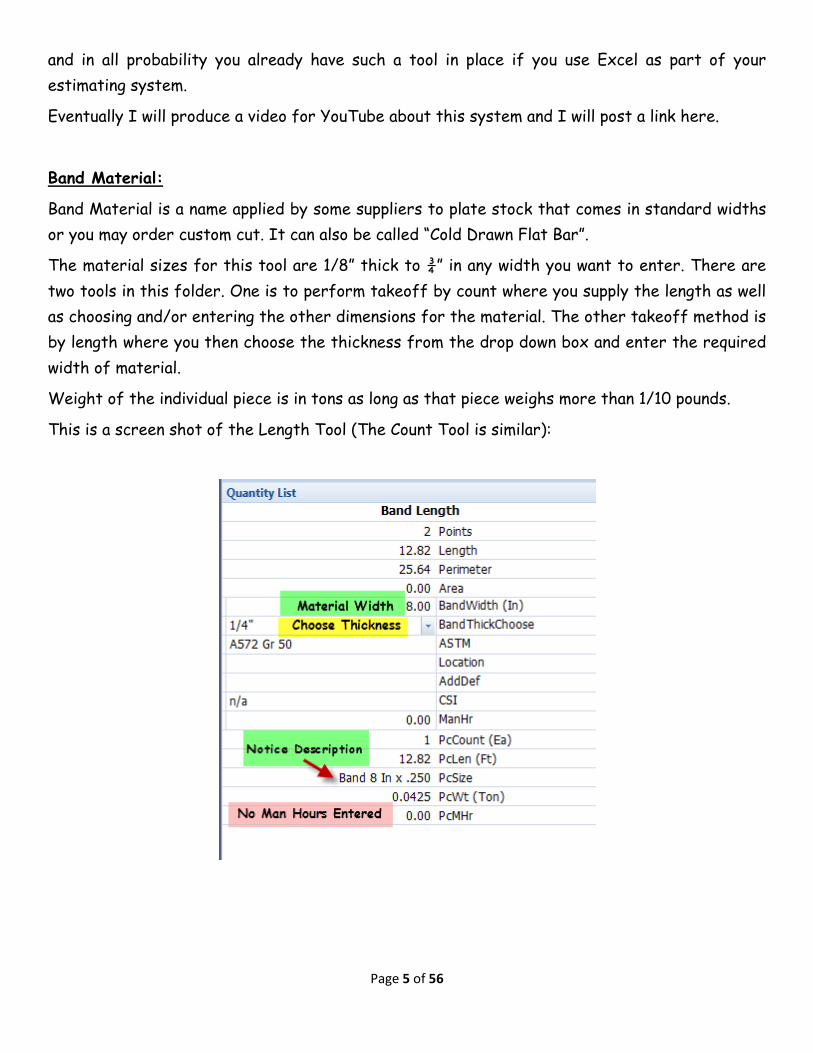
Weight of the individual piece is in tons as long as that piece weighs more than 1/10 pounds.
This is a screen shot of the Length Tool (The Count Tool is similar):
Page 6 of 56
Though I did not enter information in the Location or the AddDef text boxes they can be used to identify where the piece is located and to note whether it is galvanized or some factor you want to be sure is part of your pricing.
BASE PLATES:
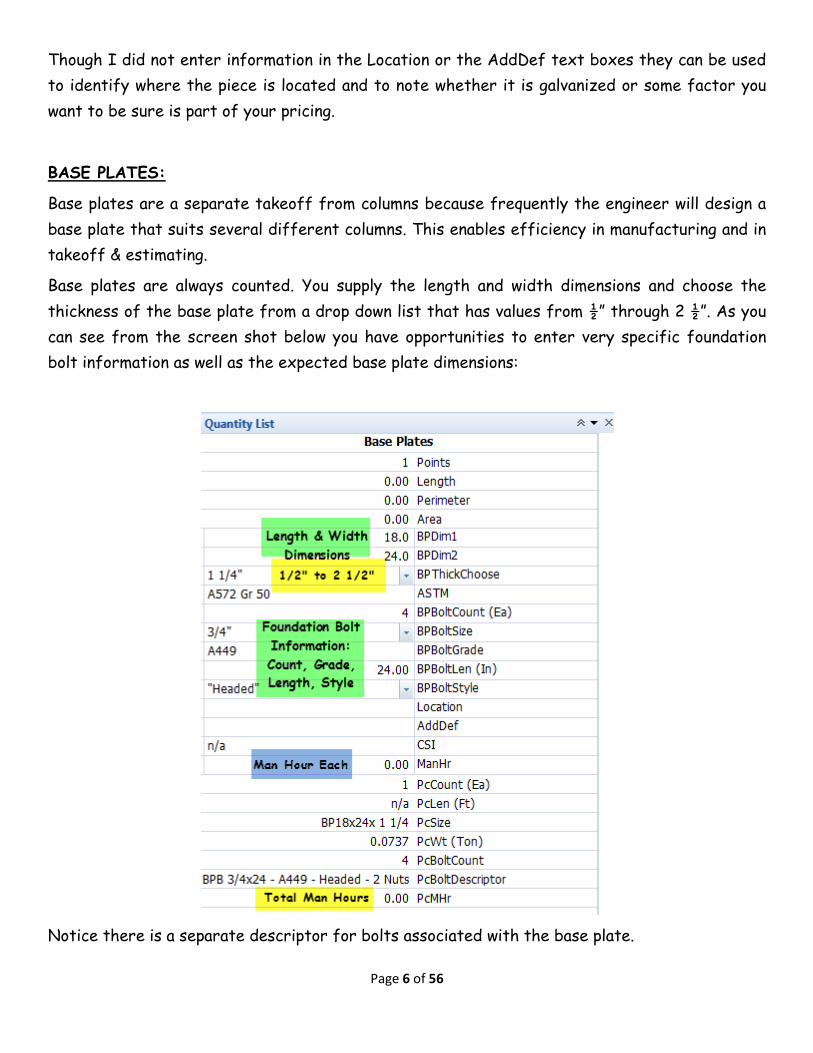
Base plates are a separate takeoff from columns because frequently the engineer will design a base plate that suits several different columns. This enables efficiency in manufacturing and in takeoff & estimating.
Base plates are always counted. You supply the length and width dimensions and choose the thickness of the base plate from a drop down list that has values from ½” through 2 ½”. As you can see from the screen shot below you have opportunities to enter very specific foundation bolt information as well as the expected base plate dimensions:
Notice there is a separate descriptor for bolts associated with the base plate.
Page 7 of 56
BEARING PAD/PLATE:
Bearing pads and plates occur frequently with any structure that has concrete. Sometimes the Structural Steel contractor supplies the component and sometimes the Concrete Contractor supplies some or all of these embedded items.
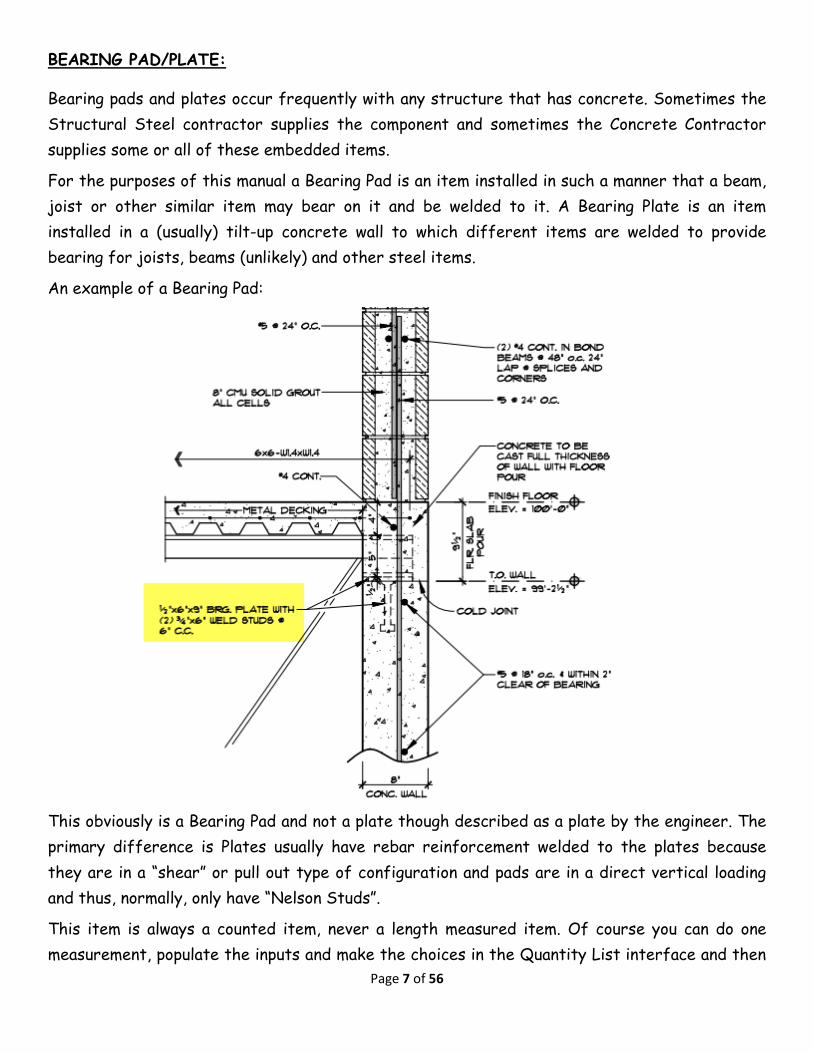
For the purposes of this manual a Bearing Pad is an item installed in such a manner that a beam, joist or other similar item may bear on it and be welded to it. A Bearing Plate is an item installed in a (usually) tilt-up concrete wall to which different items are welded to provide bearing for joists, beams (unlikely) and other steel items.
An example of a Bearing Pad:
This obviously is a Bearing Pad and not a plate though described as a plate by the engineer. The primary difference is Plates usually have rebar reinforcement welded to the plates because they are in a “shear” or pull out type of configuration and pads are in a direct vertical loading and thus, normally, only have “Nelson Studs”.
This item is always a counted item, never a length measured item. Of course you can do one measurement, populate the inputs and make the choices in the Quantity List interface and then
Page 8 of 56
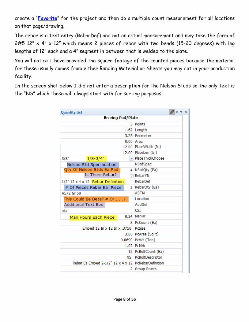
create a “Favorite” for the project and then do a multiple count measurement for all locations on that page/drawing.
The rebar is a text entry (RebarDef) and not an actual measurement and may take the form of 2#5 12” x 4” x 12” which means 2 pieces of rebar with two bends (15-20 degrees) with leg lengths of 12” each and a 4” segment in between that is welded to the plate.
You will notice I have provided the square footage of the counted pieces because the material for these usually comes from either Banding Material or Sheets you may cut in your production facility.
In the screen shot below I did not enter a description for the Nelson Studs so the only text is the “NS” which these will always start with for sorting purposes.
Page 9 of 56
CHANNEL:
Channel, in this system, comes in four different styles. Each type is described by width and weight per lineal foot as is standard with Suppliers/Manufacturers:
1. Bar Channel. 2. Junior Channel. 3. Ship Channel. 4. Standard Channel.
BAR CHANNEL:
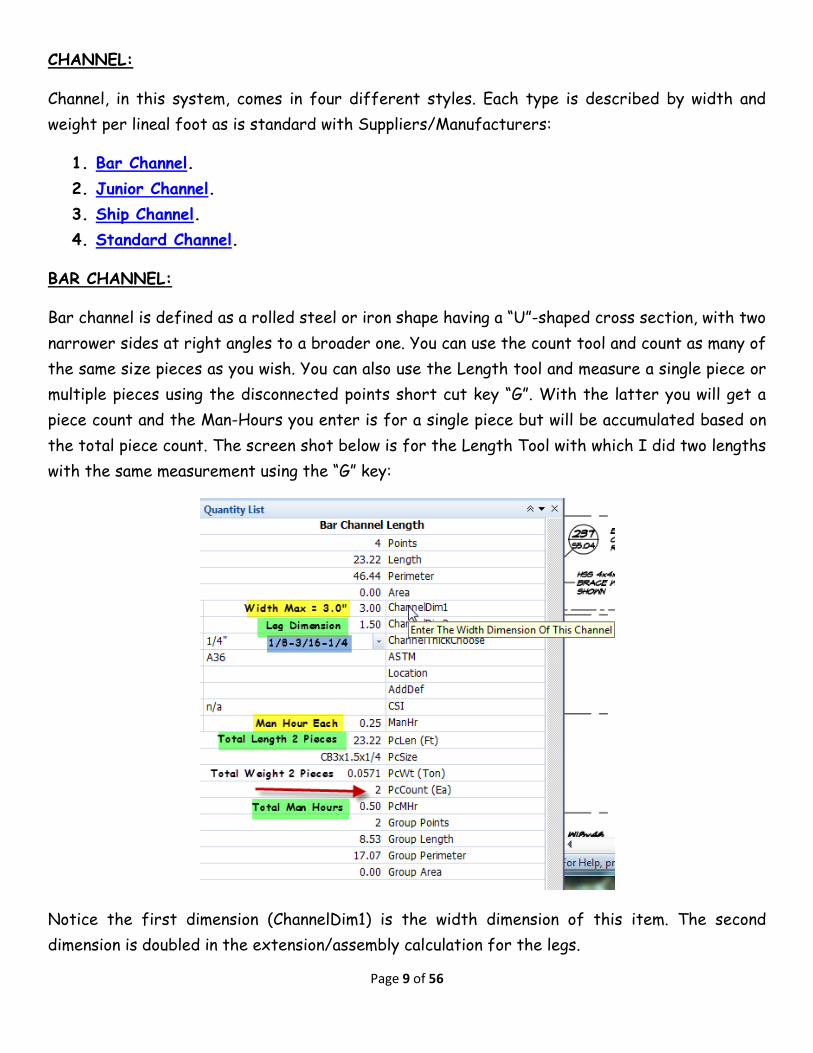
Bar channel is defined as a rolled steel or iron shape having a “U”-shaped cross section, with two narrower sides at right angles to a broader one. You can use the count tool and count as many of the same size pieces as you wish. You can also use the Length tool and measure a single piece or multiple pieces using the disconnected points short cut key “G”. With the latter you will get a piece count and the Man-Hours you enter is for a single piece but will be accumulated based on the total piece count. The screen shot below is for the Length Tool with which I did two lengths with the same measurement using the “G” key:
Notice the first dimension (ChannelDim1) is the width dimension of this item. The second dimension is doubled in the extension/assembly calculation for the legs.
Page 10 of 56
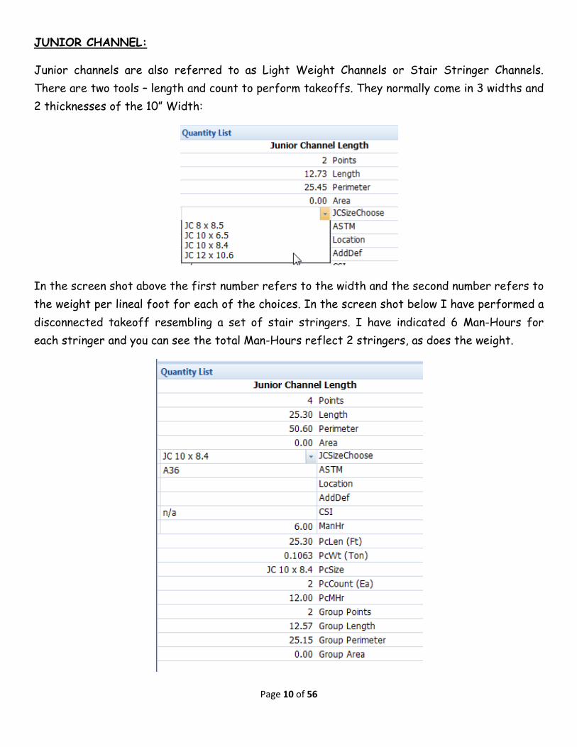
JUNIOR CHANNEL:
Junior channels are also referred to as Light Weight Channels or Stair Stringer Channels. There are two tools – length and count to perform takeoffs. They normally come in 3 widths and 2 thicknesses of the 10” Width:
In the screen shot above the first number refers to the width and the second number refers to the weight per lineal foot for each of the choices. In the screen shot below I have performed a disconnected takeoff resembling a set of stair stringers. I have indicated 6 Man-Hours for each stringer and you can see the total Man-Hours reflect 2 stringers, as does the weight.
Page 11 of 56
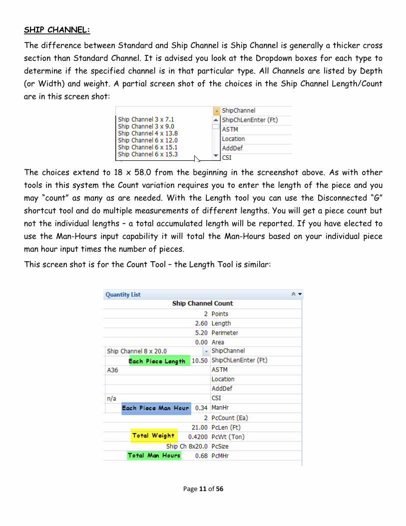
SHIP CHANNEL:
The difference between Standard and Ship Channel is Ship Channel is generally a thicker cross section than Standard Channel. It is advised you look at the Dropdown boxes for each type to determine if the specified channel is in that particular type. All Channels are listed by Depth (or Width) and weight. A partial screen shot of the choices in the Ship Channel Length/Count are in this screen shot:
The choices extend to 18 x 58.0 from the beginning in the screenshot above. As with other tools in this system the Count variation requires you to enter the length of the piece and you may “count” as many as are needed. With the Length tool you can use the Disconnected “G” shortcut tool and do multiple measurements of different lengths. You will get a piece count but not the individual lengths – a total accumulated length will be reported. If you have elected to use the Man-Hours input capability it will total the Man-Hours based on your individual piece man hour input times the number of pieces.
This screen shot is for the Count Tool – the Length Tool is similar:
Page 12 of 56
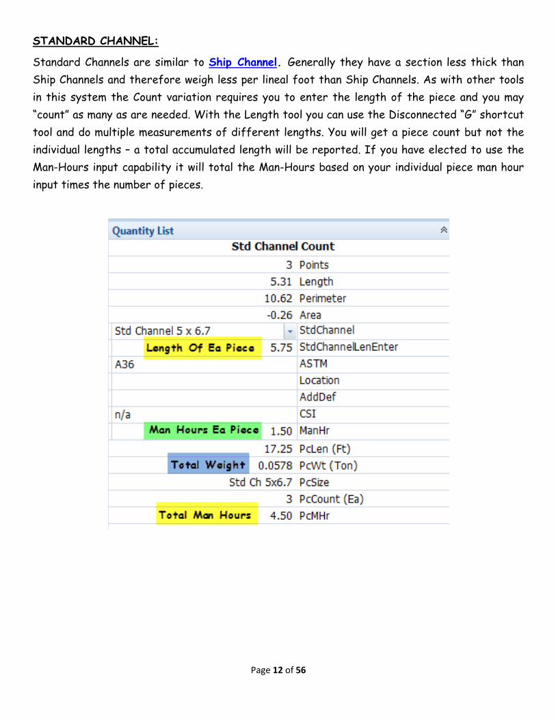
STANDARD CHANNEL:
Standard Channels are similar to Ship Channel. Generally they have a section less thick than Ship Channels and therefore weigh less per lineal foot than Ship Channels. As with other tools in this system the Count variation requires you to enter the length of the piece and you may “count” as many as are needed. With the Length tool you can use the Disconnected “G” shortcut tool and do multiple measurements of different lengths. You will get a piece count but not the individual lengths – a total accumulated length will be reported. If you have elected to use the Man-Hours input capability it will total the Man-Hours based on your individual piece man hour input times the number of pieces.
Page 13 of 56
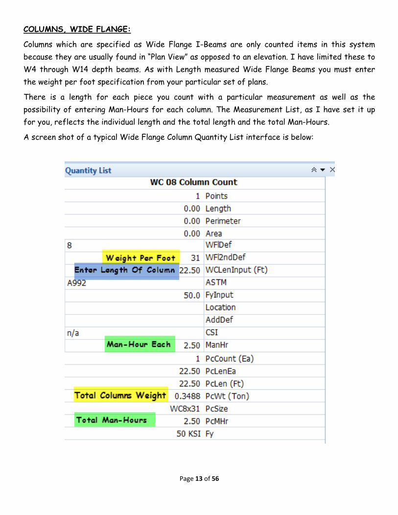
COLUMNS, WIDE FLANGE:
Columns which are specified as Wide Flange I-Beams are only counted items in this system because they are usually found in “Plan View” as opposed to an elevation. I have limited these to W4 through W14 depth beams. As with Length measured Wide Flange Beams you must enter the weight per foot specification from your particular set of plans.
There is a length for each piece you count with a particular measurement as well as the possibility of entering Man-Hours for each column. The Measurement List, as I have set it up for you, reflects the individual length and the total length and the total Man-Hours.
A screen shot of a typical Wide Flange Column Quantity List interface is below:

Page 14 of 56
CONNECTIONS:
Connections are sometimes a very detailed type of takeoff. I have used a document from Purdue University’s School of Engineering to structure the types of connections. The document is located here. Those connections found in the document are available as single or multiple types of takeoffs. They are always a counted measurement.
I have provided thickness choices from a Dropdown Box from 1/8” through to 1”. The bolt size choice is for diameter – from ½” through 1 ½”. The length of the required bolts allows for only one length – this is takeoff software, not detailing software, and will get you really close on material quantities.
There is a separate descriptor for the bolts that includes Diameter, Length & Grade and a separate data output with the quantity of bolts required for all the items counted with a single measurement.
In addition, I have used a check box type of item, “MomentXfr”, that when checked will indicate in the Measurement List that welding is required to achieve a “Moment Transfer” type of connection:
Page 15 of 56
I have supplied 5 different types of connections:
1. Angle Connection. 2. End Plate. 3. Gusset. 4. Seat Connection. 5. Shear Plate.
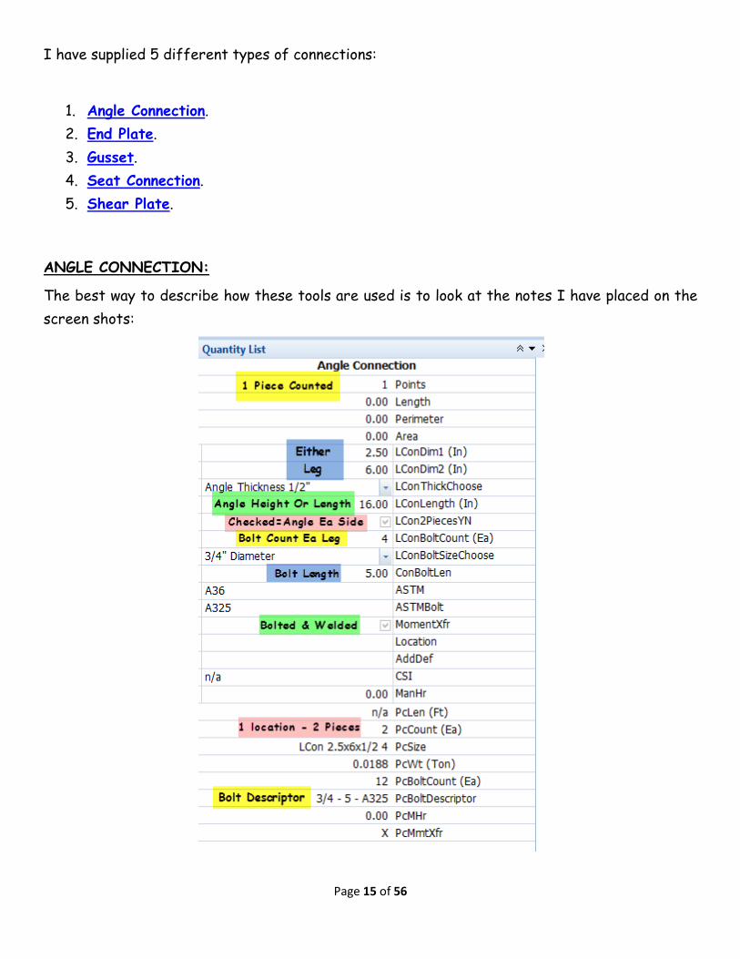
ANGLE CONNECTION:
The best way to describe how these tools are used is to look at the notes I have placed on the screen shots:
Page 16 of 56
Starting at the top of the screen shot I have clicked one point indicating one set of an Angle Connection. I have entered the width of each leg as 2 ½” and 6”. I have entered the height of the angle as 16” and said that I want an angle connection on either side. Notice below there are 2 pieces now counted. Continuing, I have indicated there are 4 bolts in each leg of each angle. This is the only connection that requires a count of bolts in each leg. The reason is to not duplicate the bolts used to connect the Angle connection through the other item. I have chosen ¾” diameter bolts from the Dropdown Box. I have entered a bolt length of 5” even though only 4 of those bolts will need that length. Lastly, I have checked the “MomentXfr” Checkbox indicating this connection will be welded as well as bolted.
If I were to continue counting connections with this criteria all counts and weights would be a function of the “points” count times the number of angles at each location – in this case two.
Of course you should practice with each of these tools until they become second nature.
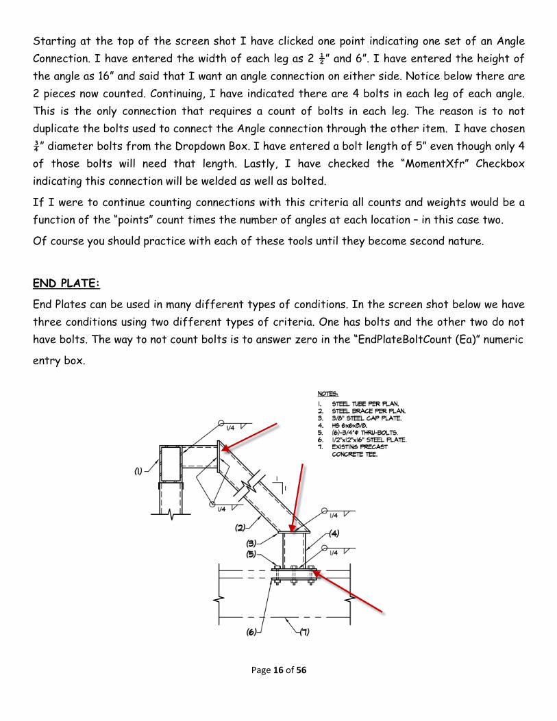
END PLATE:
End Plates can be used in many different types of conditions. In the screen shot below we have three conditions using two different types of criteria. One has bolts and the other two do not have bolts. The way to not count bolts is to answer zero in the “EndPlateBoltCount (Ea)” numeric
entry box.
Page 17 of 56
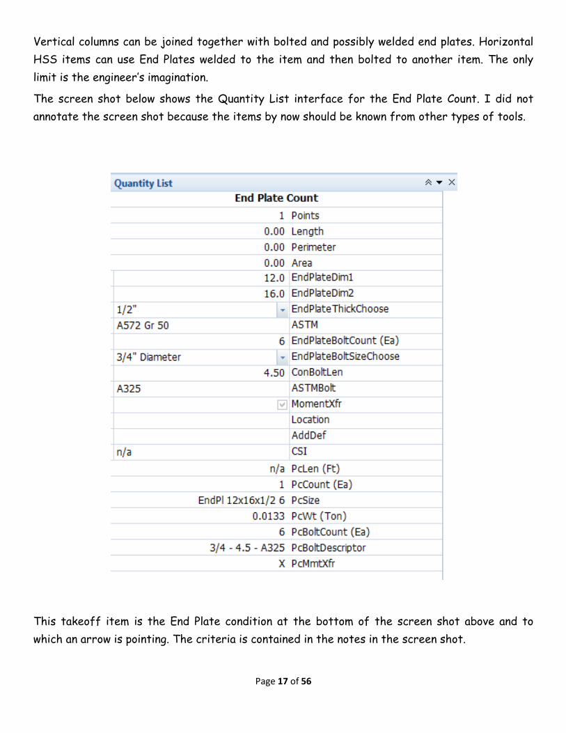
Vertical columns can be joined together with bolted and possibly welded end plates. Horizontal HSS items can use End Plates welded to the item and then bolted to another item. The only limit is the engineer’s imagination.
The screen shot below shows the Quantity List interface for the End Plate Count. I did not annotate the screen shot because the items by now should be known from other types of tools.
This takeoff item is the End Plate condition at the bottom of the screen shot above and to which an arrow is pointing. The criteria is contained in the notes in the screen shot.
Page 18 of 56
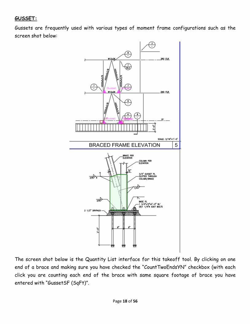
GUSSET:
Gussets are frequently used with various types of moment frame configurations such as the screen shot below:
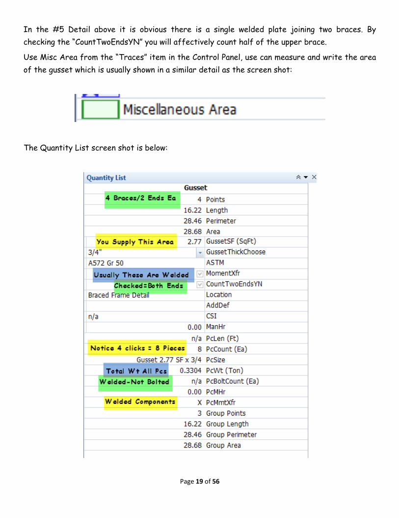
The screen shot below is the Quantity List interface for this takeoff tool. By clicking on one end of a brace and making sure you have checked the “CountTwoEndsYN” checkbox (with each click you are counting each end of the brace with same square footage of brace you have entered with “GussetSF (SqFt)”.
Page 19 of 56
In the #5 Detail above it is obvious there is a single welded plate joining two braces. By checking the “CountTwoEndsYN” you will affectively count half of the upper brace.
Use Misc Area from the “Traces” item in the Control Panel, use can measure and write the area of the gusset which is usually shown in a similar detail as the screen shot:
The Quantity List screen shot is below:
Page 20 of 56
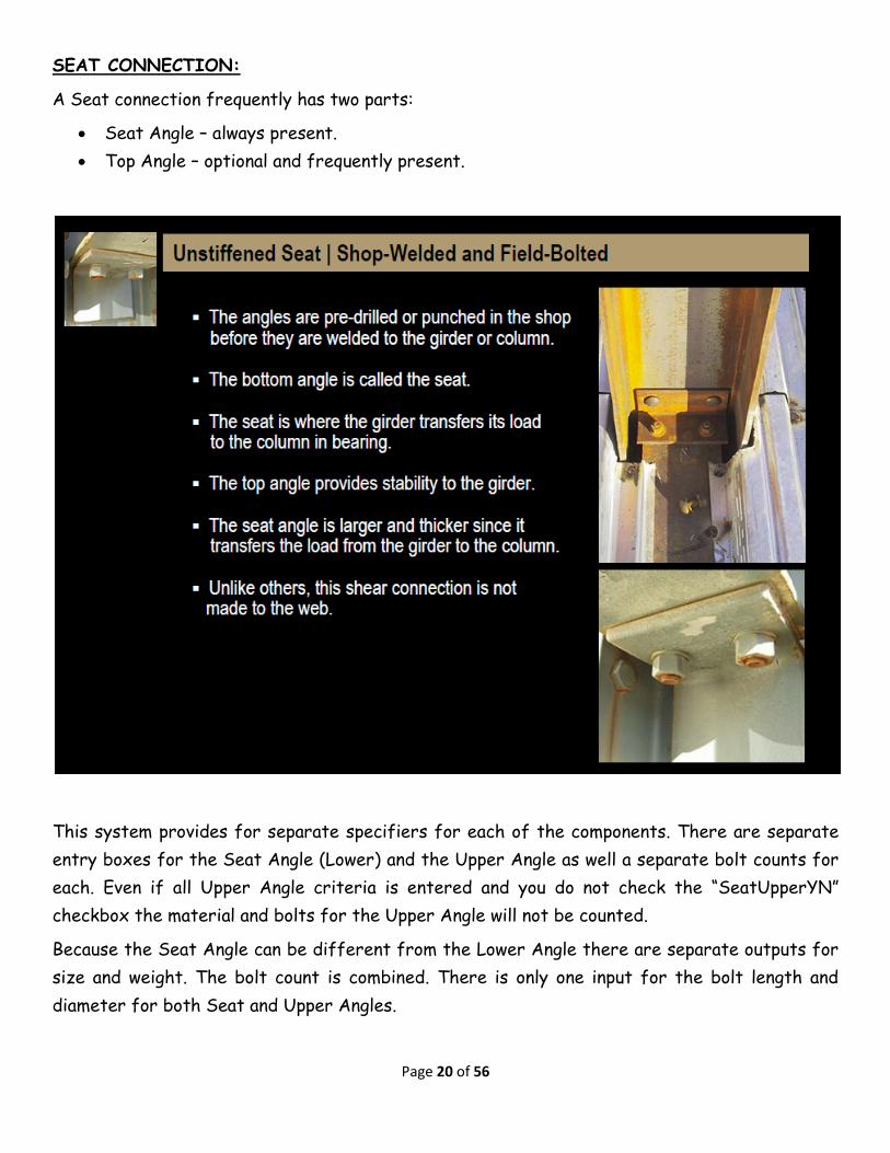
SEAT CONNECTION:
A Seat connection frequently has two parts:
• Seat Angle – always present. • Top Angle – optional and frequently present.
This system provides for separate specifiers for each of the components. There are separate entry boxes for the Seat Angle (Lower) and the Upper Angle as well a separate bolt counts for each. Even if all Upper Angle criteria is entered and you do not check the “SeatUpperYN” checkbox the material and bolts for the Upper Angle will not be counted.
Because the Seat Angle can be different from the Lower Angle there are separate outputs for size and weight. The bolt count is combined. There is only one input for the bolt length and diameter for both Seat and Upper Angles.
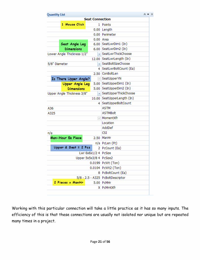
Page 21 of 56
Working with this particular connection will take a little practice as it has so many inputs. The efficiency of this is that these connections are usually not isolated nor unique but are repeated many times in a project.
Page 22 of 56
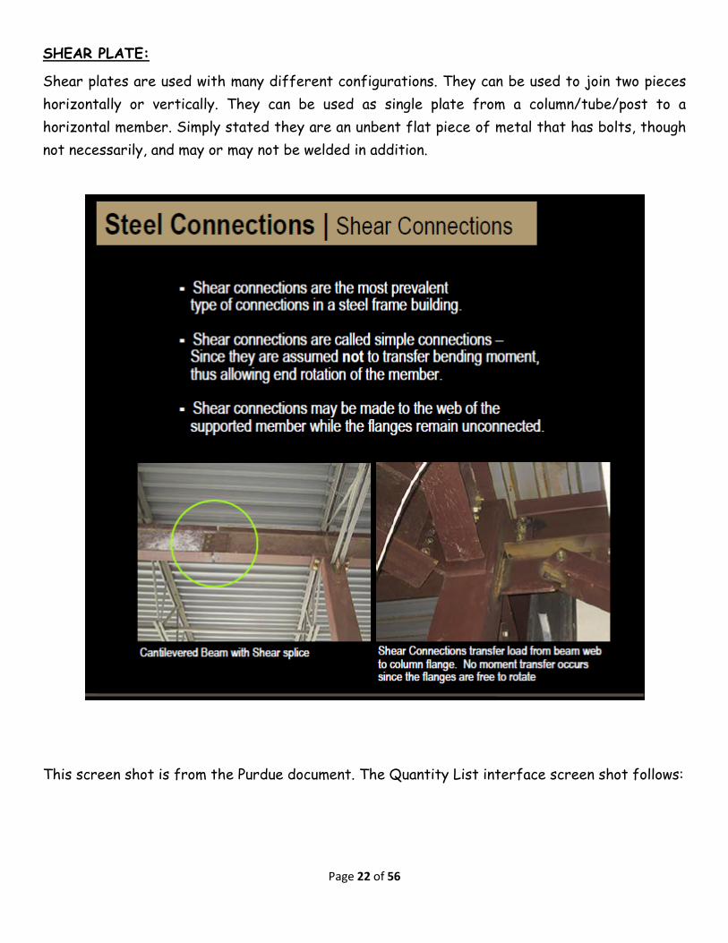
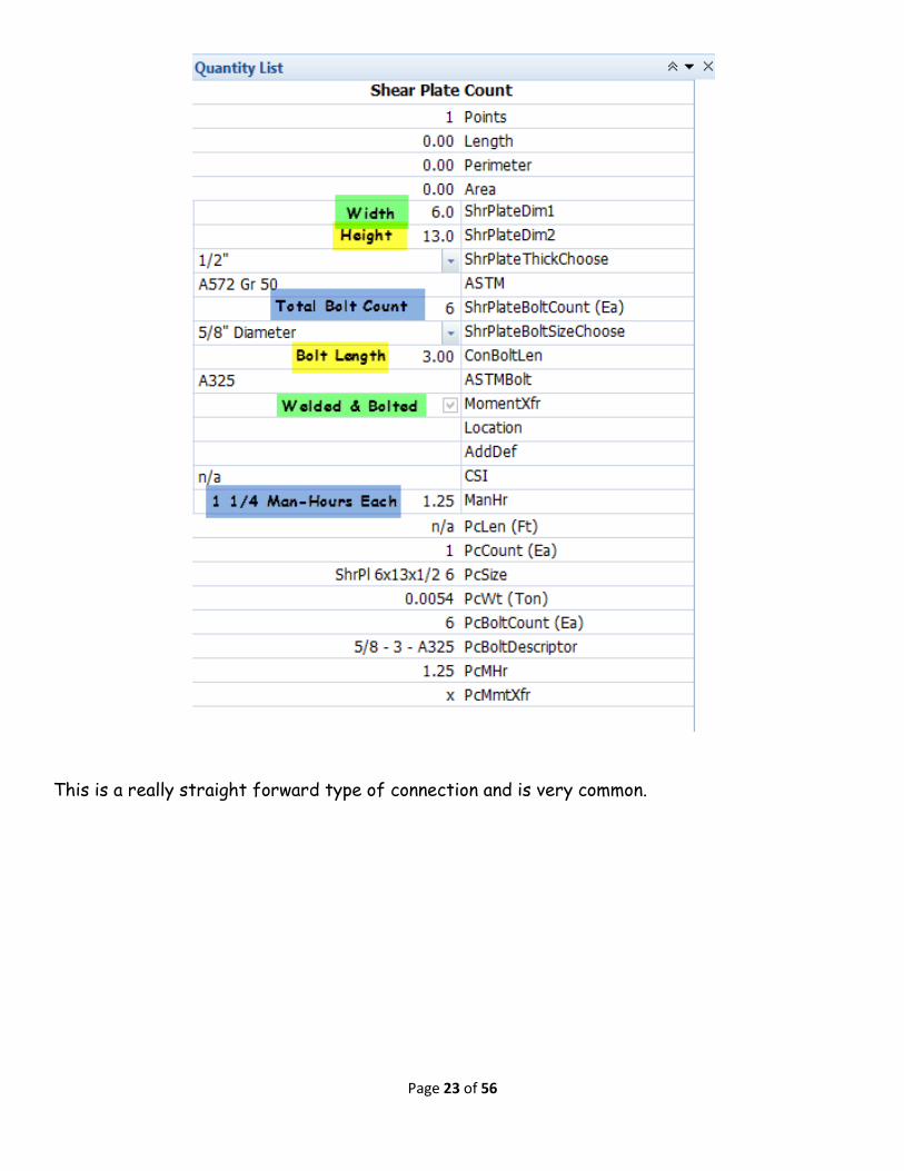
SHEAR PLATE:
Shear plates are used with many different configurations. They can be used to join two pieces horizontally or vertically. They can be used as single plate from a column/tube/post to a horizontal member. Simply stated they are an unbent flat piece of metal that has bolts, though not necessarily, and may or may not be welded in addition.
This screen shot is from the Purdue document. The Quantity List interface screen shot follows:
Page 23 of 56
This is a really straight forward type of connection and is very common.
Page 24 of 56
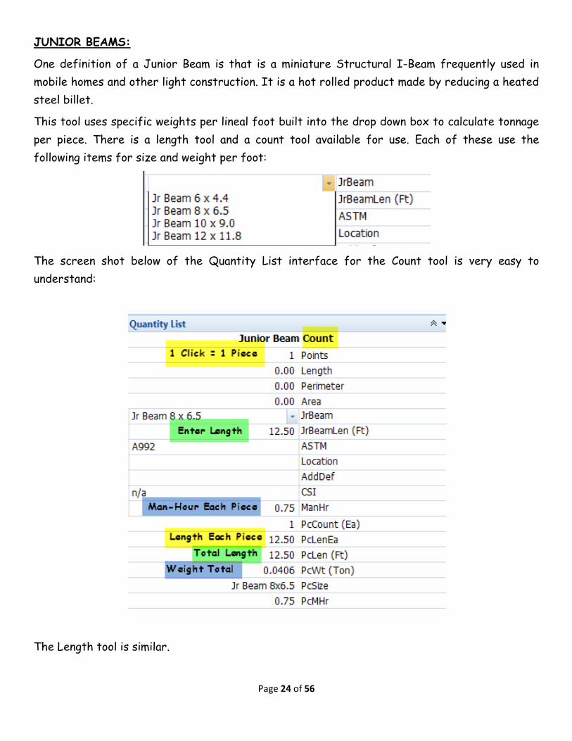
JUNIOR BEAMS:
One definition of a Junior Beam is that is a miniature Structural I-Beam frequently used in mobile homes and other light construction. It is a hot rolled product made by reducing a heated steel billet.
This tool uses specific weights per lineal foot built into the drop down box to calculate tonnage per piece. There is a length tool and a count tool available for use. Each of these use the following items for size and weight per foot:
The screen shot below of the Quantity List interface for the Count tool is very easy to understand:
The Length tool is similar.
Page 25 of 56
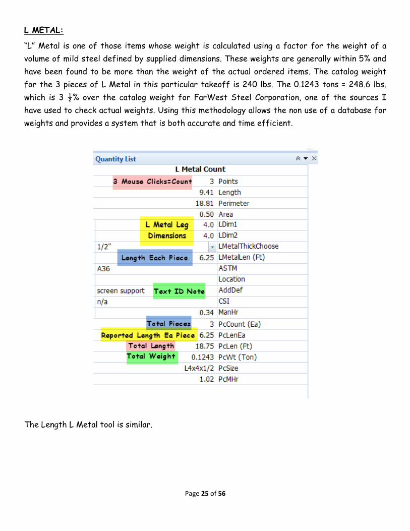
L METAL:
“L” Metal is one of those items whose weight is calculated using a factor for the weight of a volume of mild steel defined by supplied dimensions. These weights are generally within 5% and have been found to be more than the weight of the actual ordered items. The catalog weight for the 3 pieces of L Metal in this particular takeoff is 240 lbs. The 0.1243 tons = 248.6 lbs. which is 3 ½% over the catalog weight for FarWest Steel Corporation, one of the sources I have used to check actual weights. Using this methodology allows the non use of a database for weights and provides a system that is both accurate and time efficient.
The Length L Metal tool is similar.
Page 26 of 56
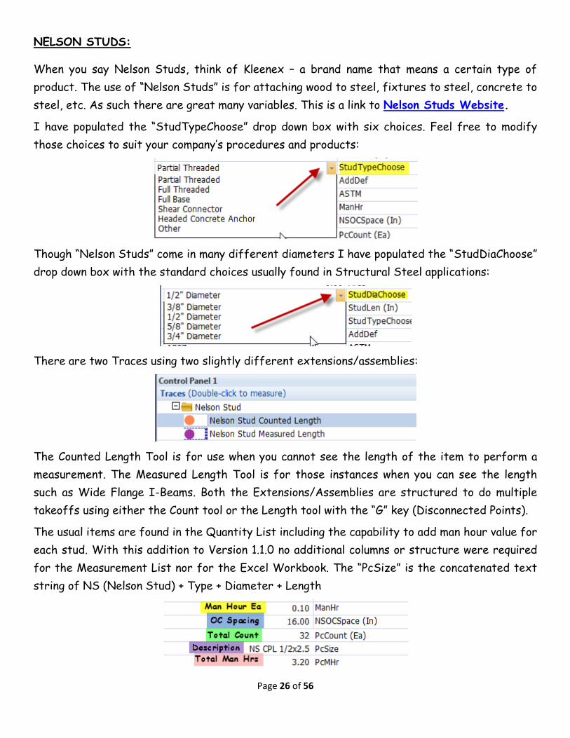
NELSON STUDS:
When you say Nelson Studs, think of Kleenex – a brand name that means a certain type of product. The use of “Nelson Studs” is for attaching wood to steel, fixtures to steel, concrete to steel, etc. As such there are great many variables. This is a link to Nelson Studs Website.
I have populated the “StudTypeChoose” drop down box with six choices. Feel free to modify those choices to suit your company’s procedures and products:
Though “Nelson Studs” come in many different diameters I have populated the “StudDiaChoose” drop down box with the standard choices usually found in Structural Steel applications:
There are two Traces using two slightly different extensions/assemblies:
The Counted Length Tool is for use when you cannot see the length of the item to perform a measurement. The Measured Length Tool is for those instances when you can see the length such as Wide Flange I-Beams. Both the Extensions/Assemblies are structured to do multiple takeoffs using either the Count tool or the Length tool with the “G” key (Disconnected Points).
The usual items are found in the Quantity List including the capability to add man hour value for each stud. With this addition to Version 1.1.0 no additional columns or structure were required for the Measurement List nor for the Excel Workbook. The “PcSize” is the concatenated text string of NS (Nelson Stud) + Type + Diameter + Length
Page 27 of 56
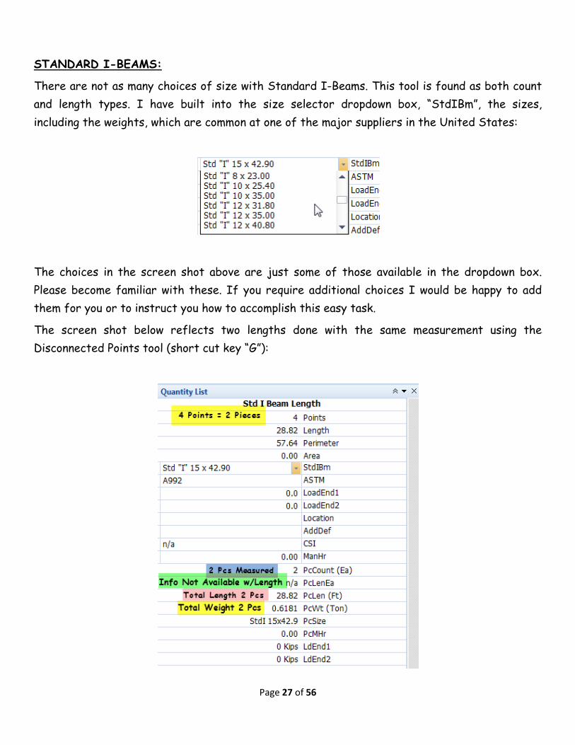
STANDARD I-BEAMS:
There are not as many choices of size with Standard I-Beams. This tool is found as both count and length types. I have built into the size selector dropdown box, “StdIBm”, the sizes, including the weights, which are common at one of the major suppliers in the United States:
The choices in the screen shot above are just some of those available in the dropdown box. Please become familiar with these. If you require additional choices I would be happy to add them for you or to instruct you how to accomplish this easy task.
The screen shot below reflects two lengths done with the same measurement using the Disconnected Points tool (short cut key “G”):
Page 28 of 56
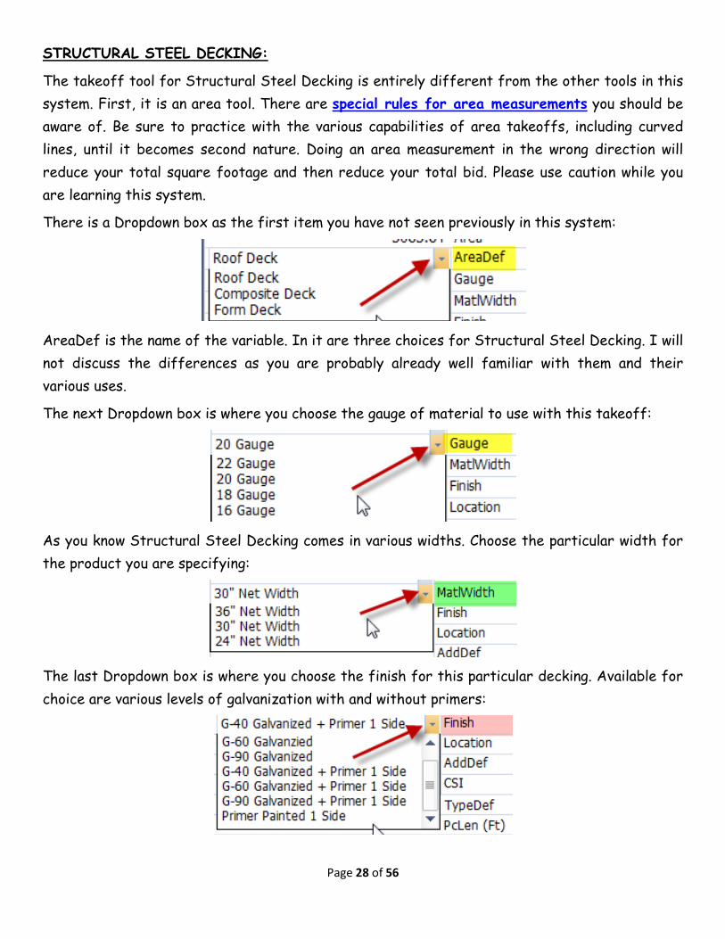
STRUCTURAL STEEL DECKING:
The takeoff tool for Structural Steel Decking is entirely different from the other tools in this system. First, it is an area tool. There are special rules for area measurements you should be aware of. Be sure to practice with the various capabilities of area takeoffs, including curved lines, until it becomes second nature. Doing an area measurement in the wrong direction will reduce your total square footage and then reduce your total bid. Please use caution while you are learning this system.
There is a Dropdown box as the first item you have not seen previously in this system:
AreaDef is the name of the variable. In it are three choices for Structural Steel Decking. I will not discuss the differences as you are probably already well familiar with them and their various uses.
The next Dropdown box is where you choose the gauge of material to use with this takeoff:
As you know Structural Steel Decking comes in various widths. Choose the particular width for the product you are specifying:
The last Dropdown box is where you choose the finish for this particular decking. Available for choice are various levels of galvanization with and without primers:
Page 29 of 56
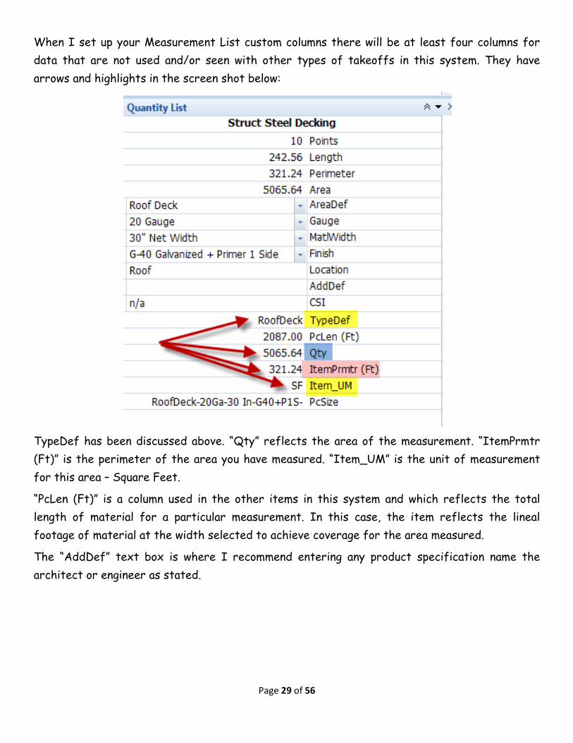
When I set up your Measurement List custom columns there will be at least four columns for data that are not used and/or seen with other types of takeoffs in this system. They have arrows and highlights in the screen shot below:
TypeDef has been discussed above. “Qty” reflects the area of the measurement. “ItemPrmtr (Ft)” is the perimeter of the area you have measured. “Item_UM” is the unit of measurement for this area – Square Feet.
“PcLen (Ft)” is a column used in the other items in this system and which reflects the total length of material for a particular measurement. In this case, the item reflects the lineal footage of material at the width selected to achieve coverage for the area measured.
The “AddDef” text box is where I recommend entering any product specification name the architect or engineer as stated.
Page 30 of 56
TUBES (HSS) SQUARE & CIRCULAR:
Tubes or Hollow Steel Sections are an interesting item for which to specify/calculate weights. I found when checking my calculated weights for circular tubes against the catalog specification weights for various diameter tubes, the catalog weights varied with tube wall thickness and were not a straight forward calculation of volume. The square and rectangular tubes calculation method first used by this system proved to have a plus or minus error rate of up to 3%. I reviewed this and version 1.2.1 is the result. In the process I found an error with Far West’s catalog of weights (5x4 x ¼” was listed as 14.49#/ft.
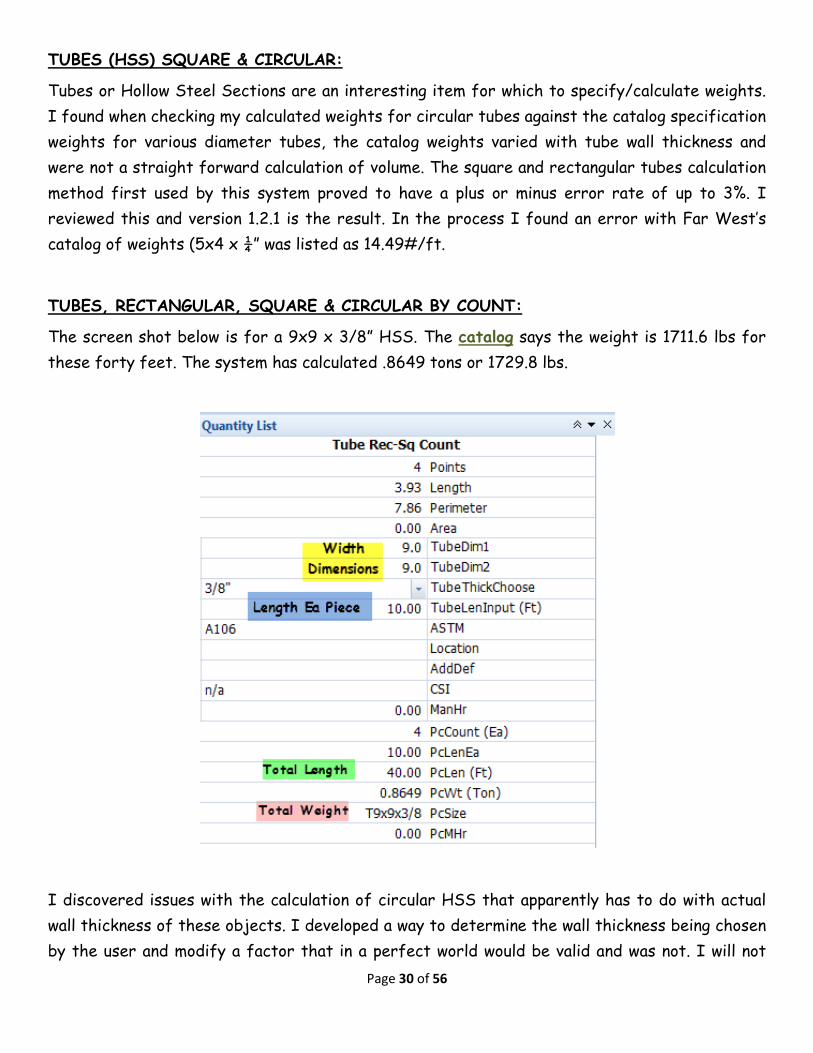
TUBES, RECTANGULAR, SQUARE & CIRCULAR BY COUNT:
The screen shot below is for a 9x9 x 3/8” HSS. The catalog says the weight is 1711.6 lbs for these forty feet. The system has calculated .8649 tons or 1729.8 lbs.
I discovered issues with the calculation of circular HSS that apparently has to do with actual wall thickness of these objects. I developed a way to determine the wall thickness being chosen by the user and modify a factor that in a perfect world would be valid and was not. I will not

Page 31 of 56
discuss how and where in the assemblies/extensions this calculation takes place but I will show the table of results based on 200 feet of count with corresponding thicknesses found in this catalog on pages 45 through 49:
Wall Diameter Catalog Calculated Thickness Inches Weight Weight 1/8 6 1568.6 1577.0 3/16 6 2334.0 2344.4 1/4 12 6274.0 6283.0 5/16 6 3802.0 3819.0 3/8 10 7710.0 7713.0 1/2 12 12,282.0 12,297.0 5/8 10 12,516.0 12,529.0 3/4 12 18,022.0 18,042.0 1 12 23,500.0 23,506.0
A typical Quantity List interface for a Circular Tube Count is below:
Should you require other wall thicknesses for HSS Circular Tube, please contact me and I will add it to this system. The catalog had diameters ranging from very small to 12”. It did not have diameters listed larger than 12”. It also had fractional diameters which will not influence the
Page 32 of 56
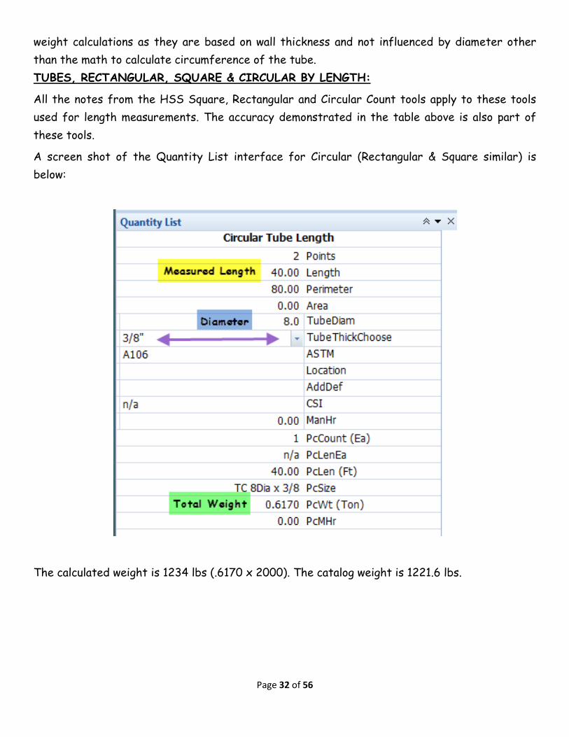
weight calculations as they are based on wall thickness and not influenced by diameter other than the math to calculate circumference of the tube. TUBES, RECTANGULAR, SQUARE & CIRCULAR BY LENGTH:
All the notes from the HSS Square, Rectangular and Circular Count tools apply to these tools used for length measurements. The accuracy demonstrated in the table above is also part of these tools.
A screen shot of the Quantity List interface for Circular (Rectangular & Square similar) is below:
The calculated weight is 1234 lbs (.6170 x 2000). The catalog weight is 1221.6 lbs.
Page 33 of 56
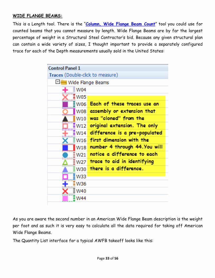
WIDE FLANGE BEAMS:
This is a Length tool. There is the “Column, Wide Flange Beam Count” tool you could use for counted beams that you cannot measure by length. Wide Flange Beams are by far the largest percentage of weight in a Structural Steel Contractor’s bid. Because any given structural plan can contain a wide variety of sizes, I thought important to provide a separately configured trace for each of the Depth measurements usually sold in the United States:
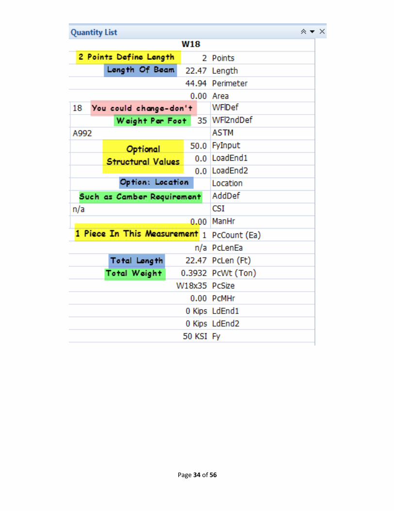
As you are aware the second number in an American Wide Flange Beam description is the weight per foot and as such it is very easy to calculate all the data required for taking off American Wide Flange Beams.
The Quantity List interface for a typical AWFB takeoff looks like this:
Page 34 of 56
Page 35 of 56
THE eTAKEOFF ENVIRONMENT:
In this section we will discuss what needs to be done to effectively use the eTakeoff system and these tools. This section will deal with minimum version requirements, toolbar setups, importing the eTakeoff Standards file, the Control Panels, Favorites and more. Normally, I will set this up on your computer the first time using GoToMeeting. These environment notes and instructions are here for reference in case you turn something off or uncheck a box and it produces unexpected results.
WHAT TO DO FIRST:
If your version of eTakeoff is not at least 3.02-61 then upgrade your software. This set of tools will not function correctly in any older versions of eTakeoff.
Save the attached “Struct Steel Stds.tsx” to your eTakeoff projects folder first. You must have purchased this system or be running a trial version of eTakeoff Premier. Premier gives access to the extension capabilities and is not a requirement for this system when purchased. The purchase price of this system includes the eTakeoff Extension Add-In and Complete Care for the Extension Add-In as well as an eTakeoff Advanced License and Complete Care for eTakeoff Advanced for 12 months. After 12 months Complete Care should be renewed every 12 months to continue access to new versions – eTakeoff is always getting better as evidenced by these tools.
Page 36 of 56
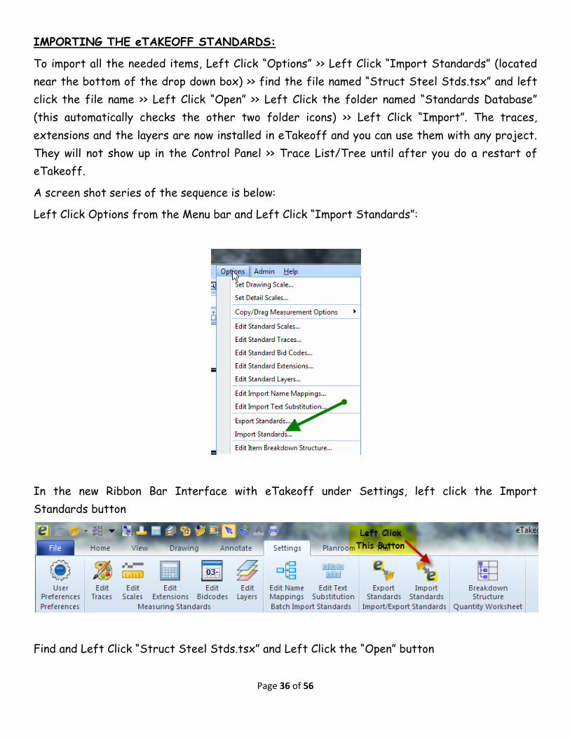
IMPORTING THE eTAKEOFF STANDARDS:
To import all the needed items, Left Click “Options” >> Left Click “Import Standards” (located near the bottom of the drop down box) >> find the file named “Struct Steel Stds.tsx” and left click the file name >> Left Click “Open” >> Left Click the folder named “Standards Database” (this automatically checks the other two folder icons) >> Left Click “Import”. The traces, extensions and the layers are now installed in eTakeoff and you can use them with any project. They will not show up in the Control Panel >> Trace List/Tree until after you do a restart of eTakeoff.
A screen shot series of the sequence is below:
Left Click Options from the Menu bar and Left Click “Import Standards”:
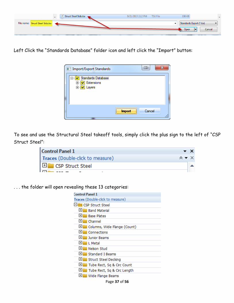
In the new Ribbon Bar Interface with eTakeoff under Settings, left click the Import Standards button
Find and Left Click “Struct Steel Stds.tsx” and Left Click the “Open” button
Page 37 of 56
Left Click the “Standards Database” folder icon and left click the “Import” button:
To see and use the Structural Steel takeoff tools, simply click the plus sign to the left of “CSP Struct Steel”:
. . . the folder will open revealing these 13 categories:
Page 38 of 56
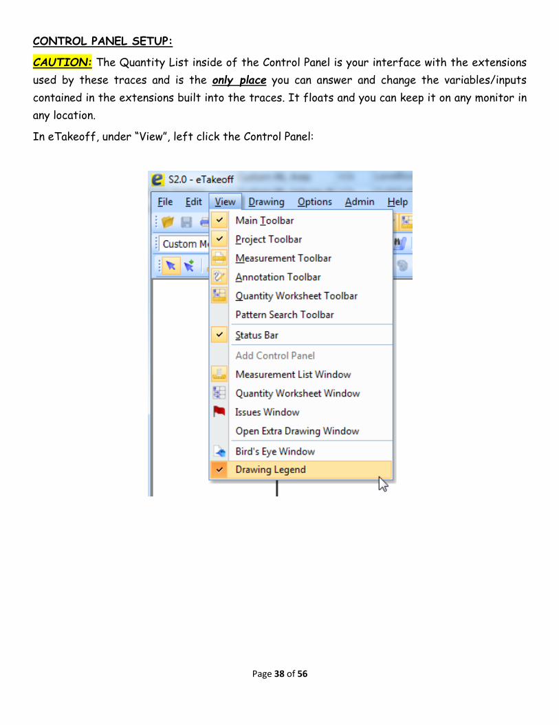
CONTROL PANEL SETUP:
CAUTION: The Quantity List inside of the Control Panel is your interface with the extensions used by these traces and is the only place you can answer and change the variables/inputs contained in the extensions built into the traces. It floats and you can keep it on any monitor in any location.
In eTakeoff, under “View”, left click the Control Panel:
Page 39 of 56
In the Control Panel, use the down arrows to add “Traces”, “Quantity List” and “Layer List”:
There are other options that can be viewed in the control panel but over the years I have used these and in this order - it works best for me. The double chevron can be clicked in each of these to collapse that particular box but all three are required to efficiently use this system.
Traces gives you access to the measuring tools. Quantity List is the input and description interface with the assemblies/extensions. Layers allow you to visibly turn on or off various measurements to not unnecessarily clutter your view.
With careful examination you may notice the “Add Control Panel”. In this screen shot it is grayed because I already have a second Control Panel open. I use the additional Control Panel for my “Favorites”.
SETTING TRACES USER PREFERENCES:
Open eTakeoff.
In the Ribbon interface left click User Preferences under File:
Page 40 of 56
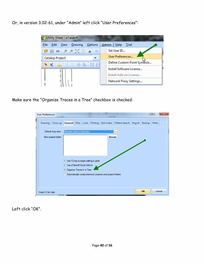
Or, in version 3.02-61, under “Admin” left click “User Preferences”:
Make sure the “Organize Traces in a Tree” checkbox is checked:
Left click “OK”.
Page 41 of 56
IMPORTING THE SAMPLE PROJECT:
To restore this project make sure the file “Struct Steel Sample ProjectExport.tpxzip” is located in the then Left Click “File” on the menu bar >> Left Click “Project Restore” (Notice the dialog window reads “Import Project . . .”) >> find the project file (“Struct Steel Sample ProjectExport.tpxzip”) and Left Click the file name >> Left Click Open >> Left Click in the “Automatically backup project after changes” check box >> Left Click “OK”. The project is restored with all the takeoffs that were done to produce and test this system. The Measurement List must be setup on each individual computer and the configurations are saved to that computer.
FAVORITES (CONTROL PANEL ITEM):
With the release of eTakeoff 3.02-46 a new capability became available. You can select annotations, measurements and groups of measurements and annotations and drag and drop them into one or both of the windows available in this particular Control Panel item. I use this for rapid reuse of notes and common types of measurements including counts. You can watch a video about this new feature here.
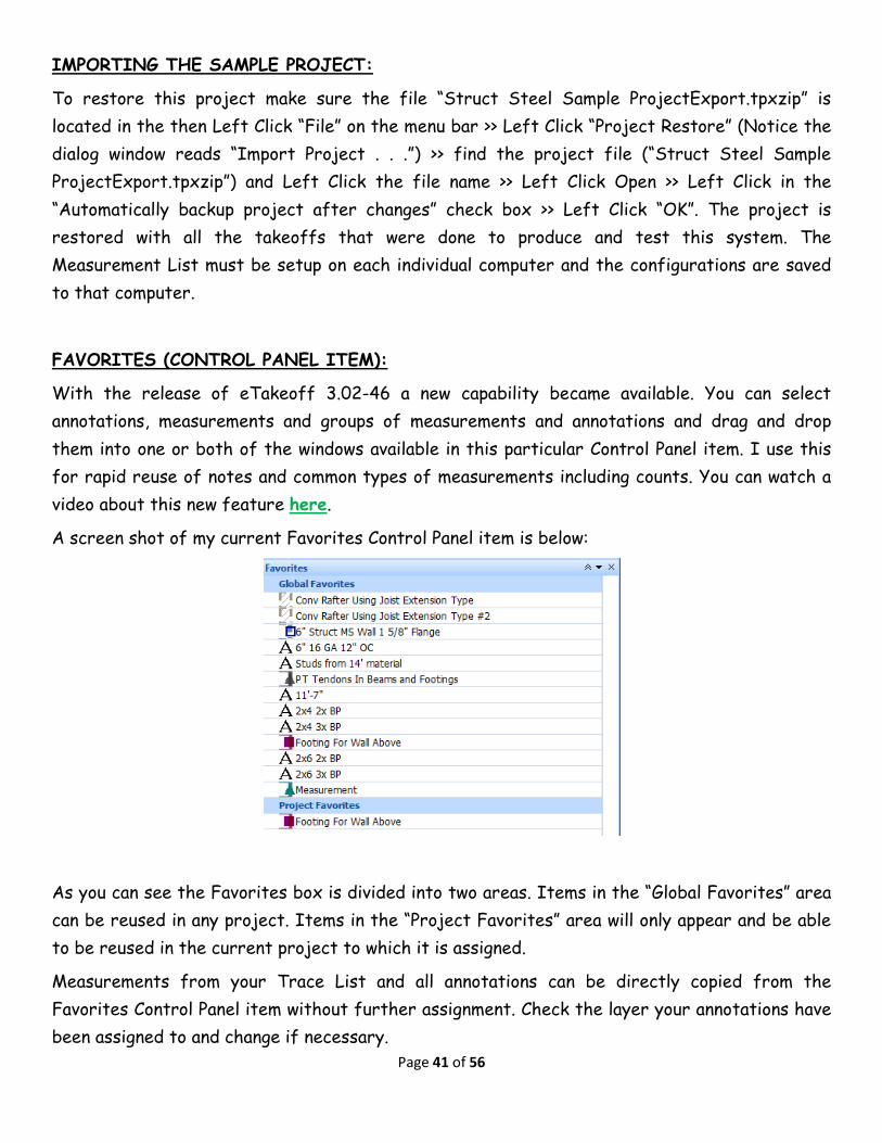
A screen shot of my current Favorites Control Panel item is below:
As you can see the Favorites box is divided into two areas. Items in the “Global Favorites” area can be reused in any project. Items in the “Project Favorites” area will only appear and be able to be reused in the current project to which it is assigned.
Measurements from your Trace List and all annotations can be directly copied from the Favorites Control Panel item without further assignment. Check the layer your annotations have been assigned to and change if necessary.
Page 42 of 56
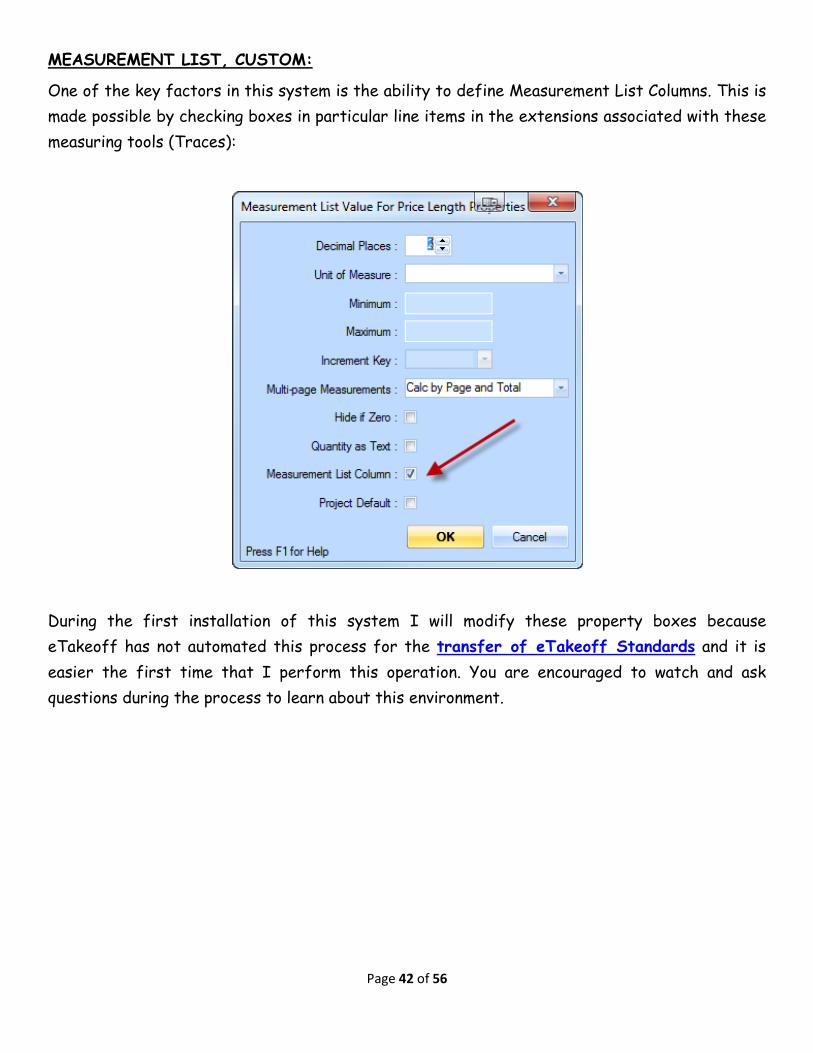
MEASUREMENT LIST, CUSTOM:
One of the key factors in this system is the ability to define Measurement List Columns. This is made possible by checking boxes in particular line items in the extensions associated with these measuring tools (Traces):
During the first installation of this system I will modify these property boxes because eTakeoff has not automated this process for the transfer of eTakeoff Standards and it is easier the first time that I perform this operation. You are encouraged to watch and ask questions during the process to learn about this environment.
Page 43 of 56
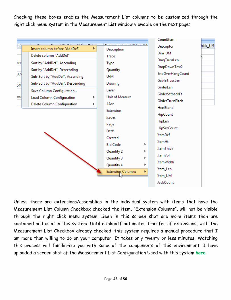
Checking these boxes enables the Measurement List columns to be customized through the right click menu system in the Measurement List window viewable on the next page:
Unless there are extensions/assemblies in the individual system with items that have the Measurement List Column Checkbox checked the item, “Extension Columns”, will not be visible through the right click menu system. Seen in this screen shot are more items than are contained and used in this system. Until eTakeoff automates transfer of extensions, with the Measurement List Checkbox already checked, this system requires a manual procedure that I am more than willing to do on your computer. It takes only twenty or less minutes. Watching this process will familiarize you with some of the components of this environment. I have uploaded a screen shot of the Measurement List Configuration Used with this system here.
Page 44 of 56
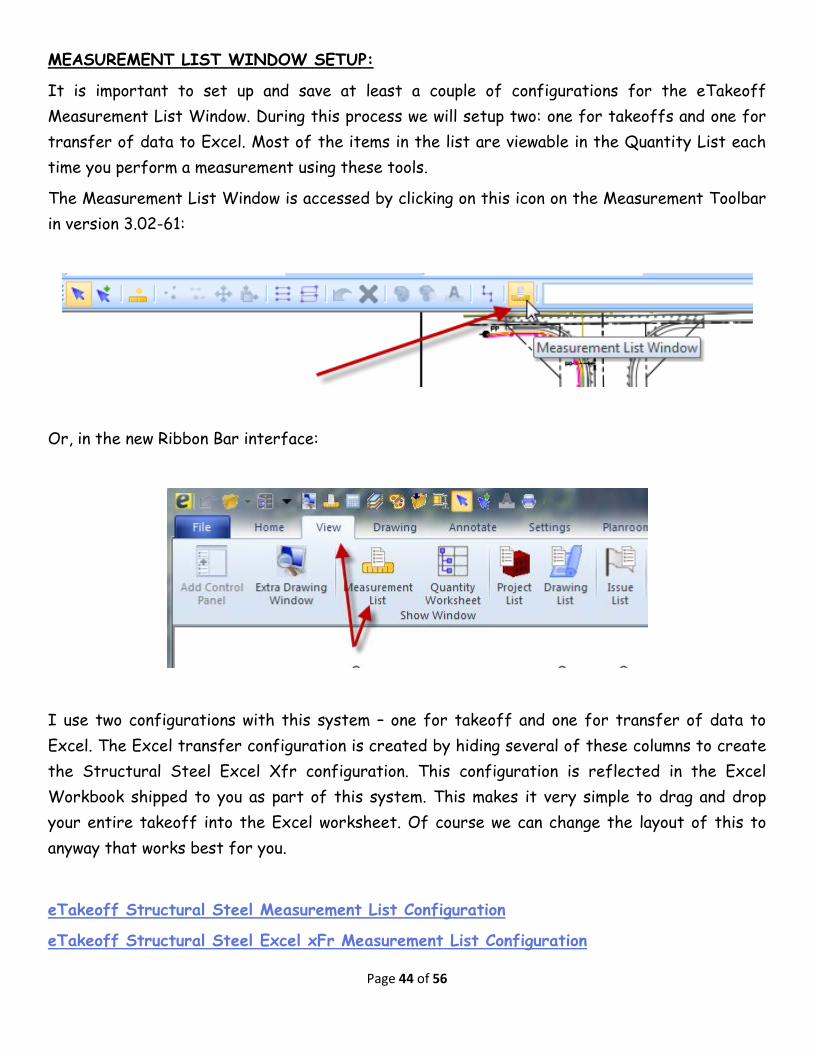
MEASUREMENT LIST WINDOW SETUP:
It is important to set up and save at least a couple of configurations for the eTakeoff Measurement List Window. During this process we will setup two: one for takeoffs and one for transfer of data to Excel. Most of the items in the list are viewable in the Quantity List each time you perform a measurement using these tools.
The Measurement List Window is accessed by clicking on this icon on the Measurement Toolbar in version 3.02-61:
Or, in the new Ribbon Bar interface:
I use two configurations with this system – one for takeoff and one for transfer of data to Excel. The Excel transfer configuration is created by hiding several of these columns to create the Structural Steel Excel Xfr configuration. This configuration is reflected in the Excel Workbook shipped to you as part of this system. This makes it very simple to drag and drop your entire takeoff into the Excel worksheet. Of course we can change the layout of this to anyway that works best for you.
eTakeoff Structural Steel Measurement List Configuration
eTakeoff Structural Steel Excel xFr Measurement List Configuration
Page 45 of 56
WORKING WITH THE eTAKEOFF ENVIRONMENT:
Be sure to use the training videos available on the eTakeoff website. This section is by no means everything you need to know about eTakeoff.
AREA TAKEOFFS:
The most important thing to remember about area takeoffs, in eTakeoff, is that a CLOCK-WISE DIRECTION ADDS FOOTAGE and a COUNTER CLOCK-WISE DIRECTION SUBTRACTS FOOTAGE. These two directions can be part of the same measurement. Perform the total area takeoff (in a clock wise direction), using the area trace you have selected, then press the letter “G” on the keyboard (notice the cursor changes to an arrow with two overlapping rectangles), left click on the beginning point of the area to be subtracted and proceed in a counter clock-wise direction around the area to be removed left clicking at each point. You will notice the hatched display of the total area now has a void in it in the shape of your counter clockwise takeoff. Now press the letter “S”. Then left click in any blank area of the drawing.
KEYBOARD SHORT-CUTS:
”N” = New Measurement. You will use this short cut the most often.
“S” = Select Mode. This is used to select a measurement or to exit from another mode.
“E” = Edit Mode. With this you can edit the points of a selected measurement.
“M” = Move/Copy. Without the CTRL key being depressed it is move; with, it is copy.
“G” = Disconnected Point. With this you can include another wall in the same measurement, for instance, or add or subtract an area to an ongoing area measurement. CAUTION: Remember clockwise area measurements add square feet and counterclockwise measurements subtract square footage. This is very useful in subtracting stair-wells, windows and doors from siding takeoffs, etc.
“C” = Arc Create. This is very useful. Click a beginning point >> click an approximate midpoint >> left click an ending point. An arc is created on the drawing with the points criteria you have set up in:
Menu bar >> Admin >> User Preferences >> Drawing >> Degrees between arc points (Mine is set at five).
Page 46 of 56
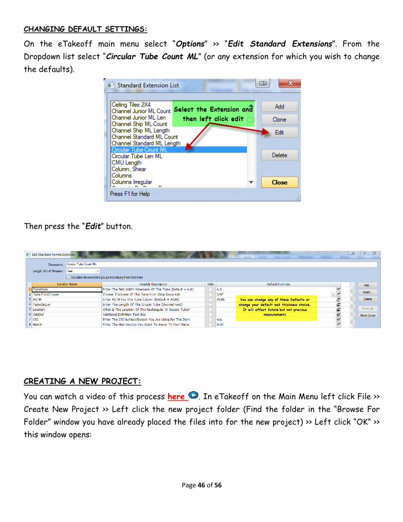
CHANGING DEFAULT SETTINGS:
On the eTakeoff main menu select “Options” >> “Edit Standard Extensions”. From the Dropdown list select “Circular Tube Count ML” (or any extension for which you wish to change the defaults).
Then press the “Edit” button.
CREATING A NEW PROJECT:
You can watch a video of this process here . In eTakeoff on the Main Menu left click File >> Create New Project >> Left click the new project folder (Find the folder in the “Browse For Folder” window you have already placed the files into for the new project) >> Left click “OK” >> this window opens:
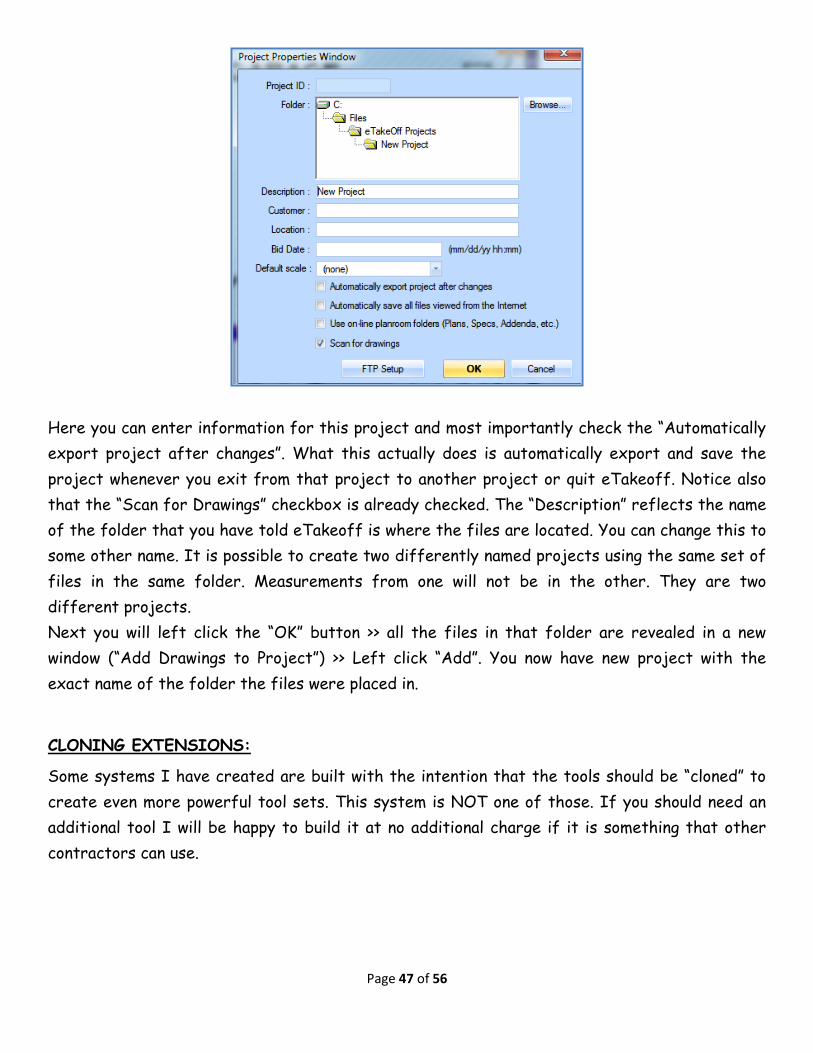
Page 47 of 56
Here you can enter information for this project and most importantly check the “Automatically export project after changes”. What this actually does is automatically export and save the project whenever you exit from that project to another project or quit eTakeoff. Notice also that the “Scan for Drawings” checkbox is already checked. The “Description” reflects the name of the folder that you have told eTakeoff is where the files are located. You can change this to some other name. It is possible to create two differently named projects using the same set of files in the same folder. Measurements from one will not be in the other. They are two different projects. Next you will left click the “OK” button >> all the files in that folder are revealed in a new window (“Add Drawings to Project”) >> Left click “Add”. You now have new project with the exact name of the folder the files were placed in.
CLONING EXTENSIONS:
Some systems I have created are built with the intention that the tools should be “cloned” to create even more powerful tool sets. This system is NOT one of those. If you should need an additional tool I will be happy to build it at no additional charge if it is something that other contractors can use.
Page 48 of 56
BACK-UPS:
By this time you have probably noticed the save button in eTakeoff is non functional – nothing happens when you click it. The reason for that is you are not directly responsible for saving your takeoff measurements. Every single measurement you make is stored in a database as you perform the measurement – not later if you remember to click a save button. There are two files created by eTakeoff and used by eTakeoff that are always in one location that are the databases used in this process. This is not the end of the eTakeoff Back-up process. You should become very familiar with all back up procedures and file management for your computer system.
There are four subjects within the subject of eTakeoff Back-ups that are, in my opinion, extremely important:
1. Traces, Extensions, Scales, Etc. These are the tools you use to measure projects. Without them there is no measuring and defining capability. You have created your own traces and possibly assemblies/extensions – protect them.
2. CTR files. These are the eTakeoff data base files that contain project information as well as all the measurements you have ever made.
3. TPX files. These are created automatically if you have checked a particular box and are not the same as TPXZIP files.
4. TPXZIP files. These files are only created manually. The contain all the project information, traces, assemblies and measurements associated with a particular project and can contain all the drawing files in a given project (recommended).
TRACES, EXTENSIONS, SCALES, ETC:
When this system was originally installed on your computer it came with a “.tsx” file. That file contains the assemblies (extensions), traces (if applicable), and layers I have created to drive the particular system you are purchasing. Without the installation of these “.tsx” files you will not have the tools to perform the measurements described in this manual. You will probably create your own traces using existing assemblies or create your own assemblies. Possibly you will have many hours in creating these tools. Protect them. It takes only seconds – literally.
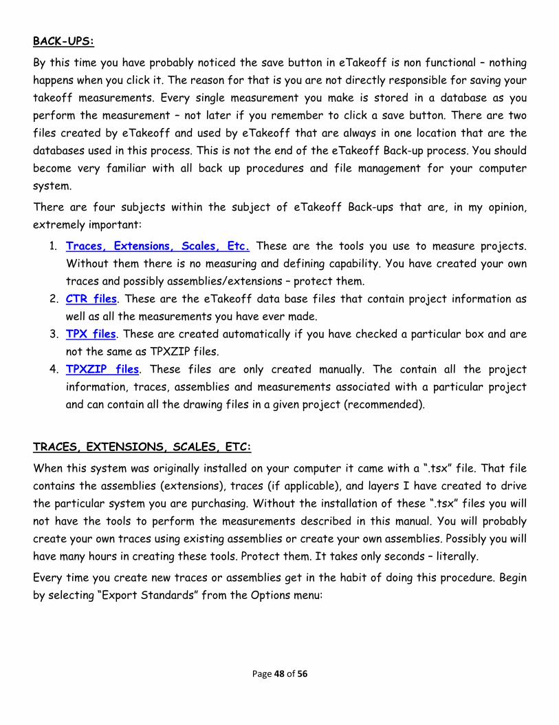
Every time you create new traces or assemblies get in the habit of doing this procedure. Begin by selecting “Export Standards” from the Options menu:
Page 49 of 56
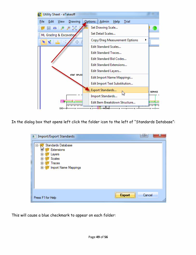
In the dialog box that opens left click the folder icon to the left of “Standards Database”:
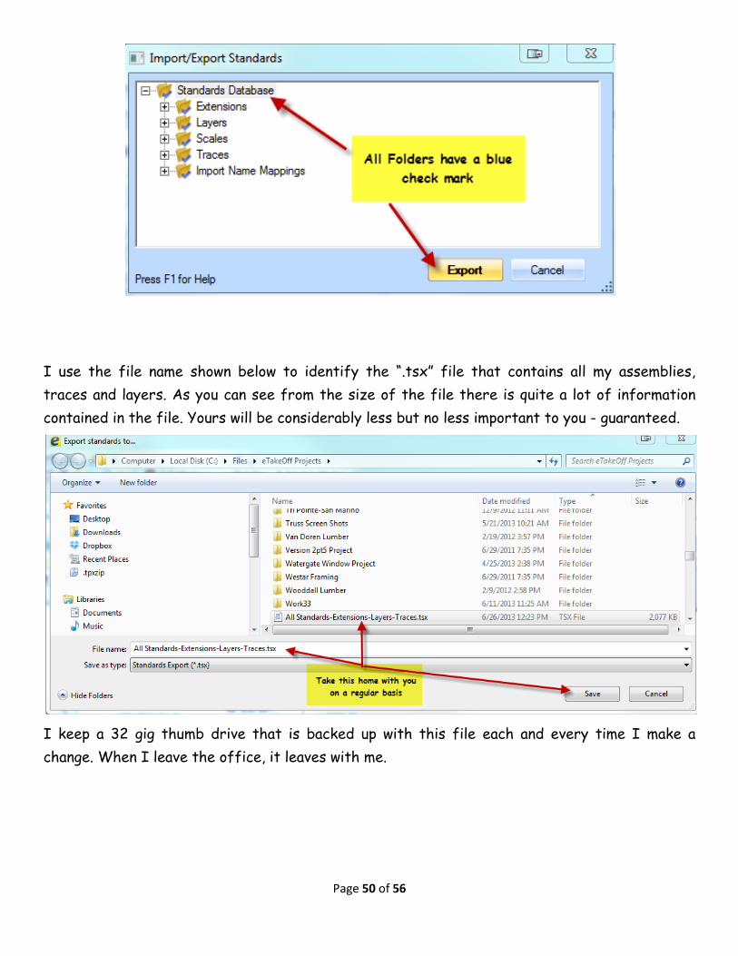
This will cause a blue checkmark to appear on each folder:
Page 50 of 56
I use the file name shown below to identify the “.tsx” file that contains all my assemblies, traces and layers. As you can see from the size of the file there is quite a lot of information contained in the file. Yours will be considerably less but no less important to you - guaranteed.
I keep a 32 gig thumb drive that is backed up with this file each and every time I make a change. When I leave the office, it leaves with me.
Page 51 of 56
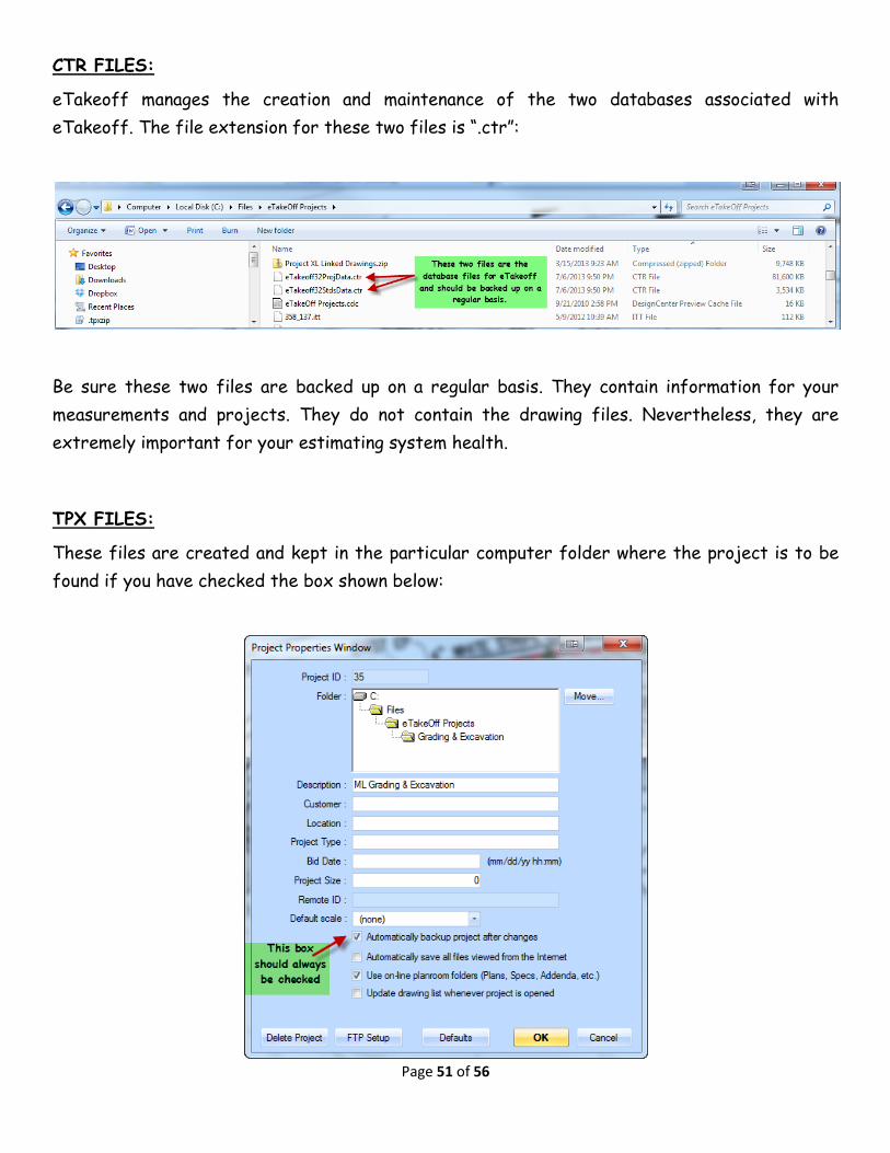
CTR FILES:
eTakeoff manages the creation and maintenance of the two databases associated with eTakeoff. The file extension for these two files is “.ctr”:
Be sure these two files are backed up on a regular basis. They contain information for your measurements and projects. They do not contain the drawing files. Nevertheless, they are extremely important for your estimating system health.
TPX FILES:
These files are created and kept in the particular computer folder where the project is to be found if you have checked the box shown below:
Page 52 of 56
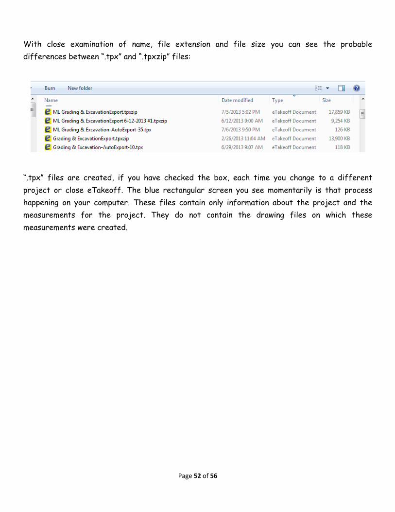
With close examination of name, file extension and file size you can see the probable differences between “.tpx” and “.tpxzip” files:
“.tpx” files are created, if you have checked the box, each time you change to a different project or close eTakeoff. The blue rectangular screen you see momentarily is that process happening on your computer. These files contain only information about the project and the measurements for the project. They do not contain the drawing files on which these measurements were created.
Page 53 of 56
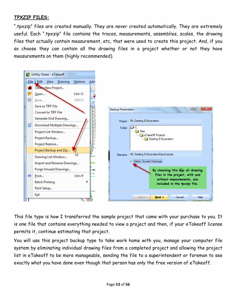
TPXZIP FILES:
“.tpxzip” files are created manually. They are never created automatically. They are extremely useful. Each “.tpxzip” file contains the traces, measurements, assemblies, scales, the drawing files that actually contain measurement, etc, that were used to create this project. And, if you so choose they can contain all the drawing files in a project whether or not they have measurements on them (highly recommended).
This file type is how I transferred the sample project that came with your purchase to you. It is one file that contains everything needed to view a project and then, if your eTakeoff license permits it, continue estimating that project.
You will use this project backup type to take work home with you, manage your computer file system by eliminating individual drawing files from a completed project and allowing the project list in eTakeoff to be more manageable, sending the file to a superintendent or foreman to see exactly what you have done even though that person has only the free version of eTakeoff.

Page 54 of 56
Many companies use this file type to keep dated files of a project’s progress by inserting a date into the suggested file name during the creation of this file. It takes less than a minute to create one of these even if the drawing files number 100 pages. Take advantage of this powerful tool.
EXCEL WORKBOOK SAMPLE:
I have provided an Excel Workbook, Struct Steel ML Takeoff Template.xlsx, with one worksheet for use as a receptor for the Measurement List output. It is structured the same way as the Structural Steel Excel Xfr Measurement List configuration so the data dragged and dropped from eTakeoff matches in both locations.
VERSION HISTORY:
Version 1.0.0: Original version published September 2013
Version 1.1.0: January 1, 2014. Added Nelson Stud capability to system.
Version 1.2.0: February 17, 2014. Added Bearing Pad/Plate capability to system.
Version 1.2.1: March 1, 2014. Changed calculation method for HSS rectangular and square.
Version 1.2.2: June 11, 2014. User found WC column weight calculation error. Corrected and fix sent to existing customers.
Version 1.3.0: July 21, 2016. Added the capability of Shop Hours and Field Hours for each item in the fourteen categories. Prior to this version there was only one Man-Hour entry possible. The Measurement List Columns have been changed to include the single item Man-Hour entry and the Total Man-Hour entry for each measurement.
Page 55 of 56
COPYRIGHT:
This document is the sole property of CSP Construction Technology (Caddy Shack Productions – CSP, hereafter) and is designed to supplement any documentation and videos available through the eTakeoff Website. CSP is an authorized reseller of eTakeoff software products. As such, CSP has developed extensions, traces and other tools that are part of takeoff systems which are the sole property of CSP. This document, and the files shipped electronically with this document, are the sole property of CSP and are designed to supplement any documentation and videos available through the eTakeoff Website. There are some videos referenced in this document that are the property of eTakeoff, LLC, and utilize their website and distribution system. They are the sole property of eTakeoff, LLC, and they reserve all rights. Other videos linked in this document go to the CSP YouTube website and are intended as instructional media in connection with this document and other training documents intended for customers of CSP, an authorized Reseller of eTakeoff. CSP reserves all rights. You are authorized to use the software associated with this document on any computer in your company in accordance with the sales agreement between CSP and your company. You may not sell, loan, or otherwise allow others to use this document, the software this document refers to, or videos without the express written consent of CSP. You may not publish or otherwise disclose the content of any of the extensions, including to eTakeoff, LLC, to anyone outside your company. You may not transfer to eTakeoff any project file containing traces and associated extensions created by CSP. They are considered proprietary and are the intellectual property of Chad Langhans, CSP, and shall never enter public domain. If you are granted access to this software through a Trial License and choose not to purchase eTakeoff you must destroy this document and erase all software delivered to you for the purpose of using eTakeoff in a Trial Evaluation. Your agreement to these conditions is deemed valid and binding upon your acceptance of the Trial License installation procedure and acceptance of the installation of this software on your computer.
Page 56 of 56
Contact me with any questions, training requirements or comments.
Chad Langhans CSP Construction Technology
Cell: 760-822-7182
Skype: chad.langhans
email: [email protected]


![USE OF TAKEOFF CHARTS [B737] - International … maximum takeoff weight (MTOW) for airplanes, based on structural or other limits. On the other hand, ... TORA: 2011 m. TODA: 2111 m.](https://static.fdocuments.in/doc/165x107/5b189fe27f8b9a23258be7cc/use-of-takeoff-charts-b737-international-maximum-takeoff-weight-mtow-for-airplanes.jpg)