INSTRUCTION MANUAL P-51 MUSTANG EP (40) - The ... Span Wing Area Flying Weight Fuselage Length 49 in...
16
Wing Span Wing Area Flying Weight Fuselage Length 49 in / 1250 mm 434 sq in / 28 sq dm 3.6 Ib / 1650 g 43 in / 1090 mm Specifications *Specifications are subject to change without notice.* INSTRUCTION MANUAL P-51 MUSTANG EP (40) 450W Motor System Requires: 5-channel radio w/ 5 mini servos, Outrunner Motor KM0374810, w/ Propeller Adaptor HW2340300, 40A Brushless ESC with 11x8E propeller, 4 cells 14.8V 3200 mAh Li - Po battery & charger. FACTORY PRE-FABRICATED ALMOST-READY-TO-FLY(ARF)SERIES MADE IN CHINA Warning ! This model is not a toy. It is designed for maximum performance. Please seek advice if one is not familiar with this kind of electric powered precision model. Operating this model without prior preparation may cause injuries. Remember, safety is the most important thing. Always keep this instruction manual at hand for quick reference. The World Models Manufacturing Co., Ltd. www.theworldmodels.com E287XMPO17530807
Transcript of INSTRUCTION MANUAL P-51 MUSTANG EP (40) - The ... Span Wing Area Flying Weight Fuselage Length 49 in...
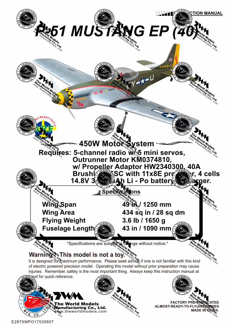
Wing SpanWing AreaFlying WeightFuselage Length
49 in / 1250 mm434 sq in / 28 sq dm3.6 Ib / 1650 g43 in / 1090 mm
Specifications
*Specifications are subject to change without notice.*
INSTRUCTION MANUAL
P-51 MUSTANG EP (40)
450W Motor SystemRequires: 5-channel radio w/ 5 mini servos, Outrunner Motor KM0374810, w/ Propeller Adaptor HW2340300, 40A Brushless ESC with 11x8E propeller, 4 cells 14.8V 3200 mAh Li - Po battery & charger.
FACTORY PRE-FABRICATEDALMOST-READY-TO-FLY(ARF)SERIES
MADE IN CHINA
Warning ! This model is not a toy.It is designed for maximum performance. Please seek advice if one is not familiar with this kindof electric powered precision model. Operating this model without prior preparation may causeinjuries. Remember, safety is the most important thing. Always keep this instruction manual athand for quick reference.
The World ModelsManufacturing Co., Ltd.www.theworldmodels.com
E287XMPO17530807

P. 1
INDEXBEFORE YOU BEGIN P.1
PARTS LIST P.2
SAFETY PRECAUTIONS P.11
BEFORE YOU BEGIN
ASSEMBLY P.3-P.11
Check all parts. If you find any defective or missing parts contact your local dealer. Please DRY FITand check for defects for all parts that will require CA or Epoxy for final assembly. Any parts youfind to be defective after the gluing process may be difficult to remove for warranty replacement. Themanufacturer will replace any defective parts, but will not extend to the parts that are good before gluing to defective parts during assembly. Warranty will not cover any parts modified by customer.
Read through the manual before you begin, so you will have an overall idea of what to do.
Symbols used throughout this instruction manual comprise of the following : -
1
2
3
3mm
Do not overlook this symbol!
Cut off shaded portion.Peel off shaded portioncovering film.
Pay close attention here!
Pierce the shaded portioncovering film.
Must be purchased separately!
Drill holes with the specifieddiameter (here: 3mm).
Ensure smooth non-bindingmovement while assembling.
Apply instant glue(C.A.glue, super glue.)
Assemble left and rightsides the same way.
Apply epoxy glue.
Applythreadlocker
P-51 MUSTANG EP (40)
E287XMPO17530807
P.2
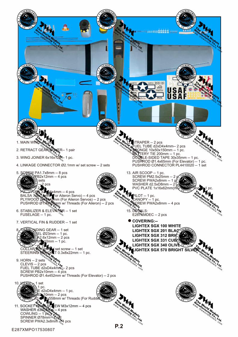
Parts List 1. MAIN WING -- 1 pair 2. RETRACT GEAR COVER-- 1 pair
3. WING JOINER 6x16x126 -- 1 pc.
4. LINKAGE CONNECTOR Ø2.1mm w/ set screw -- 2 sets
5. SCREW PA1.7x8mm -- 8 pcs SCREW PB2x12mm -- 4 pcs HORN -- 2 sets STRAPER -- 2 pcs CLEVIS -- 2 pcs FUEL TUBE d2xD4x4mm -- 4 pcs BALSA 7x8x13mm (For Aileron Servo) -- 4 pcs PLYWOOD 2x48x48mm (For Aileron Servos) -- 2 pcs PUSHROD Ø1.4x108mm w/ Threads (For Aileron) -- 2 pcs
6. STABILIZER & ELEVATOR -- 1 set FUSELAGE -- 1 pc.
7. VERTICAL FIN & RUDDER -- 1 set
8. TAIL LANDING GEAR -- 1 set TAIL WHEEL Ø23mm -- 1 pc. SCREW PA2.6x12mm -- 2 pcs SCREW PM2x10mm -- 1 pc. M2 NUT -- 1 pc. COLLAR Ø1.7mm w/ set screw -- 1 set STEERING BRACKET 0.3x8x22mm -- 1 pc.
9. HORN -- 2 sets CLEVIS -- 2 pcs FUEL TUBE d2xD4x4mm -- 2 pcs SCREW PB2x10mm -- 4 pcs PUSHROD Ø1.4x452mm w/ Threads (For Elevator) -- 2 pcs
10. HORN -- 1 set CLEVIS -- 1 pc. FUEL TUBE d2xD4x4mm -- 1 pc. SCREW PB2x10mm -- 2 pcs PUSHROD Ø1.4x558mm w/ Threads (For Rudder) -- 1 pc.
11. SOCKET HEAD SCREW M3x12mm -- 4 pcs WASHER d3xD7mm -- 4 pcs COWLING -- 1 pc. SPINNER Ø78mm-- 1 set SCREW PWA2.3x8mm -- 4 pcs
12. STRAPER -- 2 pcs FUEL TUBE d2xD4x4mm-- 2 pcs SPONGE 10x50x150mm -- 1 pc. BATTERY TIE 200mm -- 1 pc. DOUBLE-SIDED TAPE 30x35mm -- 1 pc. PUSHROD Ø1.4x65mm (For Elevator) -- 1 pc. PUSHROD CONNECTOR PL4410020 -- 1 set
13. AIR SCOOP -- 1 pc. SCREW PM2.5x25mm -- 2 pcs SCREW PWA2x8mm -- 1 pcs WASHER d2.5xD8mm -- 2 pcs PVC PLATE 1x16x62mm(Wing Protection) -- 1 pc.
14. PILOT -- 1 pc. CANOPY -- 1 pc. SCREW PWA2x8mm -- 4 pcs
15. DECALS: E287XMDEC -- 2 pcs
COVERING:--LIGHTEX SGX 100 WHITELIGHTEX SGX 201 BLACKLIGHTEX SGX 312 BRIGHT REDLIGHTEX SGX 331 CUB YELLOWLIGHTEX SGX 340 OLIVE DRABLIGHTEX SGX 570 BRIGHT SILVER
E287XMPO17530807
P.3
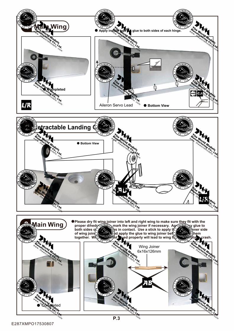
Main Wing1
2
Apply instant type CA glue to both sides of each hinge.
Completed
Bottom View
Bottom View
Aileron Servo Lead
Retractable Landing Gear
Main Wing 3
Completed
Please dry fit wing joiner into left and right wing to make sure they fit with the proper dihedral angle, mark the wing joiner if necessary. Apply epoxy glue to both sides of all surfaces in contact. Use a stick to apply the glue to inner side of wing joiner sleeve, and apply the glue to wing joiner before putting them together. Wing joiner not glued properly will lead to wing failure and plane crash.
Wing Joiner6x16x126mm
E287XMPO17530807
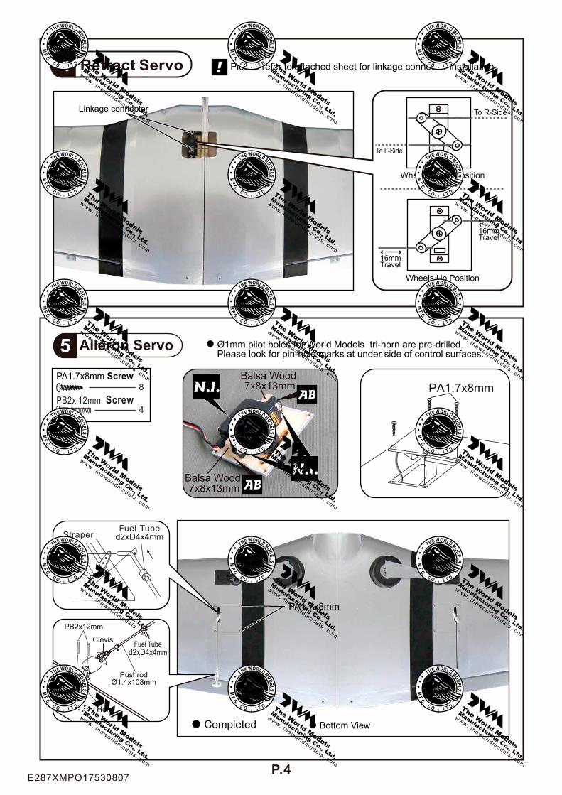
Retract Servo 4
Aileron Servo5
Bottom ViewCompleted
PA1.7x8mm Screw8
PB2x12mm
Clevis
Horn
PushrodØ1.4x108mm
Fuel Tubed2xD4x4mm
StraperFuel Tube
d2xD4x4mm
PA1.7x8mm
Ø1mm pilot holes for World Models tri-horn are pre-drilled. Please look for pin-hole marks at under side of control surfaces.
P.4
PA1.7x8mm
Balsa Wood 7x8x13mm
Balsa Wood 7x8x13mm
PB2x 12mm Screw4
To L-Side
Wheels Up Position
16mmTravel
16mmTravel
Wheels Down Position
To R-SideLinkage connector
Please refer to attached sheet for linkage connector installation.
E287XMPO17530807
P.5
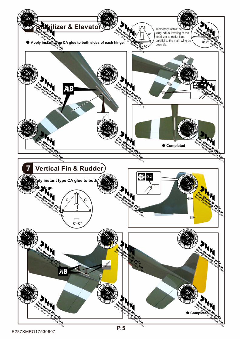
Stabilizer & Elevator6
Completed
Apply instant type CA glue to both sides of each hinge.
A A'
A=A'
(Stabi l izer)
(Main Wing)
B B'
B=B'
Temporary install the main wing, adjust leveling of thestabilizer to make it as parallel to the main wing aspossible.
Vertical Fin & Rudder7Apply instant type CA glue to both sides of
each hinge.
Completed
C C'
C=C'
E287XMPO17530807

P.6
Tail Landing Gear8
PM2x10mm Screw
PA2.6x12mm Screw PA2.6x12mm
M2 Nut 1
1
2
Bottom View PM2x10mm
M2 Nut
Steering Bracket
1.7mm Collar1
Rudder Pushrod10
Bottom View
PB2x10mm Screw 2
Ø1mm pilot holes for World Models tri-horn are pre-drilled.Please look for pin-hole marks at under side of control surfaces.
≈75mm≈29mm
Clevis
Fuel Tubed2xD4x4mm
PB2x10mm
PushrodØ1.8x558mm
Elevator Pushrod9PB2x10mm Screw
4Ø1mm pilot holes for World Models tri-horn are pre-drilled.Please look for pin-hole marks at under side of control surfaces.
≈125mm≈29mm
PB2x10mm Fuel Tubed2xD4x4mm
Clevis
PushrodØ1.4x452mm
Horn
Horn
Bottom View
3mmset screw
PA2.6x12mm
E287XMPO17530807
P.7
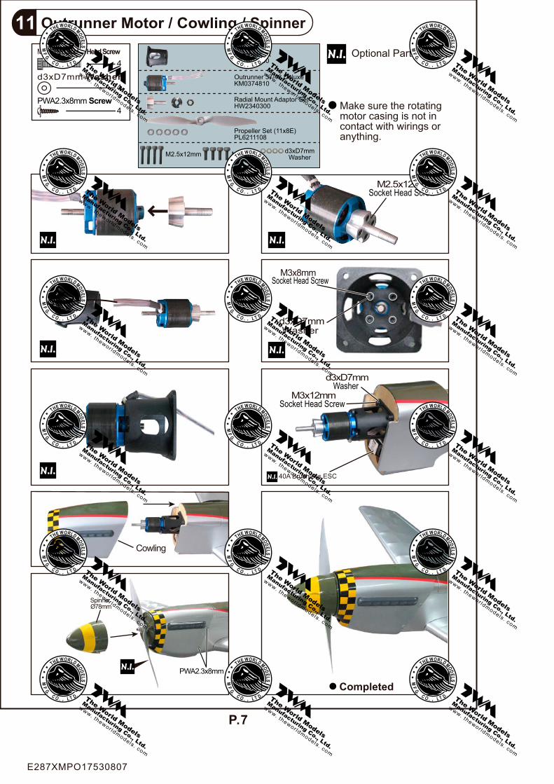
Outrunner Motor / Cowling / Spinner11
d3xD7mm Washer
M3x8mm
M2.5x12mmSocket Head Screw
M3x12mmSocket Head Screw
d3xD7mmWasher
Socket Head Screw
Make sure the rotatingmotor casing is not in contact with wirings oranything.
Optional Parts
Completed
PWA2.3x8mm Screw 4
Cowling
Spinner Ø78mm
PWA2.3x8mm
Outrunner 37/48 DeluxeKM0374810
Radial Mount Adaptor SetHW2340300
Propeller Set (11x8E)PL6211108
d3xD7mm Washer4
4M3x12mm Socket Head Screw Motor Mount
PL5404000
M3x8mm d3xD7mmWasherM2.5x12mm
40A Brushless ESC
E287XMPO17530807
P.8
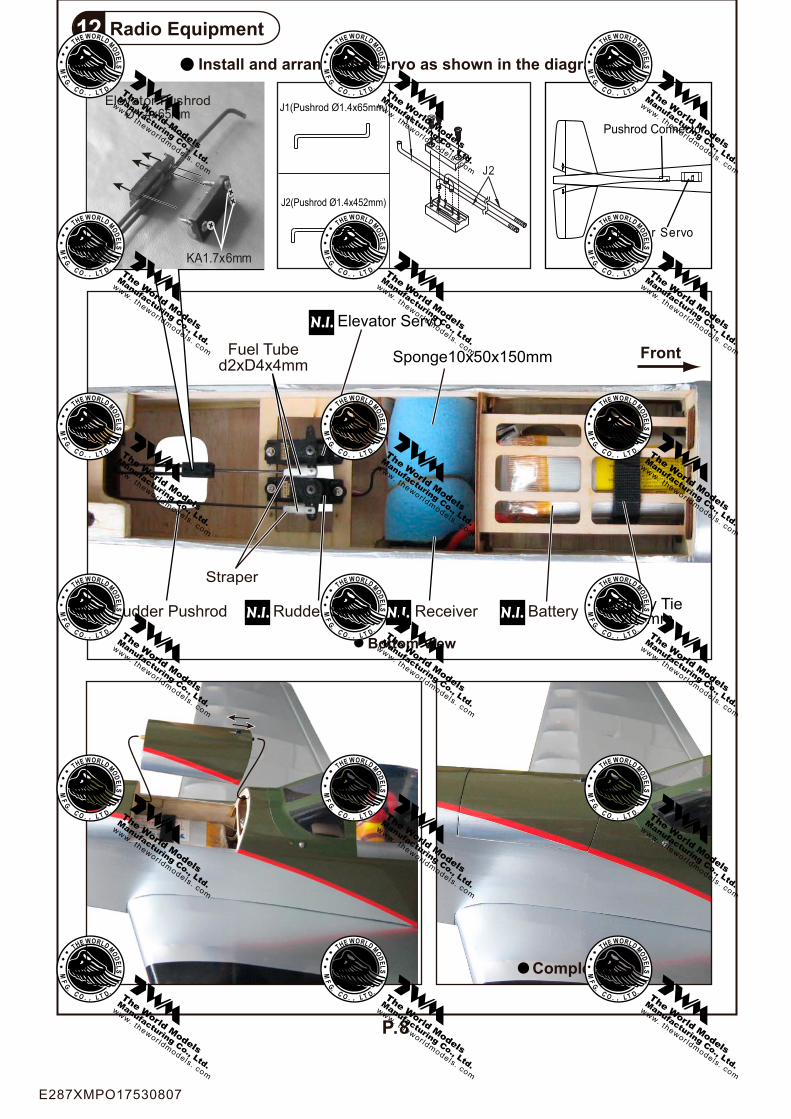
Radio Equipment12
Completed
Bottom View
Front
Install and arrange the servo as shown in the diagram.
ReceiverRudder Pushrod
Fuel Tubed2xD4x4mm
Elevator Servo
Pushrod Connector
Elevator Servo
Rudder Servo Battery Tie 200mm
KA1.7x6mm
Elevator PushrodØ1.4x65mm
Battery
J1
J2
J1(Pushrod Ø1.4x65mm)
J2(Pushrod Ø1.4x452mm)
Sponge10x50x150mm
Straper
E287XMPO17530807

P.9
Main Wing13
d2.5xD8mm Washer
PM2.5x25mm Screw
PWA2x8mm Screw
2
2
1
Canopy14PWA2x8mm Screw
4
Completed
Bottom View
PWA2x8mm
Pilot
PWA2x8mmAir Scoop
d2.5xD8mm PM2.5x25mm
PVC Plate1x16x62mm
E287XMPO17530807

P.10
Wing Setting15 Adjust the wing and fuselage configuration as shown in the diagrams.
A=A’ B=B’ C=C’ D=D’
B B’
A A’
D C C’ D’
E287XMPO17530807

P.11
Control Throws16
C.G.17
Adjust the control throws as shown in thediagram. These throws are good for generalflying. You can adjust according to yourpersonal preference.
The ideal C.G. position is 105 mm ( 4.13 in ) behind the leading edge measured at where the wing meets the fuselage. In order to obtain the C.G. specified, add weight to the fuselage or move the battery position. Check the C.G. before flying.
Rudder15 mm15 mm
Elevator10 mm
10 mm
6 mm
6 mm
Aileron
Important Safety Precautions# First time flyer should never fly by himself / herself. Assistance from experienced flyer is absolutely necessary.
# Pre-flight adjustment must be done before flying, it is very dangerous to fly a badly pre-adjusted aircraft.
# is specially designed to be powered by 450W Motor System.
# Make sure the air field is spacious, never fly the plane too close to people and never get too close to a running propeller. Extreme caution should be exercised when working with electric powered models. Make sure the propeller is cleared of all objects, especially your hands before connecting the battery to the model. Make sure you understand the operation of the ESC (Electronic Speed Control) by studying the ESC manual. Once you plug in the battery for electric powered model, always treat the propeller as a rotating one, as accidental movement of the throttle stick will spin the propeller and could cause injuries.
# If you find wrinkles on the covering as a result of weather changes, you can use hot iron to remove the wrinkles. Please begin with lower temperature setting and gradually raise the temperature until the wrinkles are gone. Too hot an iron may damage the covering. Don,t use hot iron near the seams or edges,hot iron will melt the glue and shrink the covering at the same time, causing the seams to pull away.
# Check and re-tighten up all factory assembled screws, use thread locker if necessary.
105 mm
C.G.
4.13 in
MUSTANG EP (40)
E287XMPO17530807

Drill 2mm hole at servo horn.Insert linkage connectorinto servo horn.
Make sure shoulder ofscrew is cleared fromservo horn.Add washer to reduceplay if necessary.
Shoulder
Tighten up the round nutagainst the shoulder. ApplyCA or permanent threadlocker.
After fastening the round nut, make sure thatthe linkage connector can rotate freely.
LINKAGE CONNECTORHW7111050 & HW7111060
E287XMPO17530807
Product Registration Form (US Customers)
We would like to share with you any relevant information regarding your model, includingproduct news and free upgrade parts when applicable. Please fill in the following and send toAirBorne Models, 4749-K, Bennett Drive, Livermore, CA 94551 USA.
1. Name:______________________________________________
2. Address:____________________________________________
3. Phone #:____________________ E-mail:__________________
4. Model:______________________________________________
Wing QC#__________ Fuselage QC# _______________________(QC numbers are stamped on wing and fuselage)
5. Date of Purchase:_____________________________________
6. Store Name: _________________________________________
Please call AirBorne Models at 925 371 0922 for any assistance in filling this form.Thank you very much for purchasing our product.
E287XMPO17530807
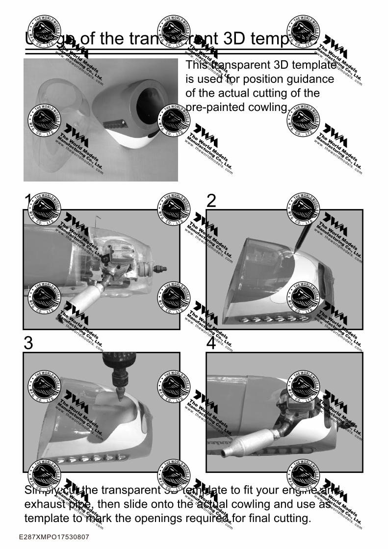
This transparent 3D templateis used for position guidanceof the actual cutting of thepre-painted cowling.
Usage of the transparent 3D template
Simply cut the transparent 3D template to fit your engine and exhaust pipe, then slide onto the actual cowling and use as template to mark the openings required for final cutting.
1 2
3 4
E287XMPO17530807

The World ModelsManufacturing Co., Ltd.www.theworldmodels.com
E287XMPO17530807