Instruction Manual - MicroChem 2 Transmitter and ...aciltd.ca/pdf/microchem2.pdf · MicroChem®2...
104
- 1 - 210.6401.20 Instruction Manual - MicroChem ® 2 Transmitter and Controller Series 4000
Transcript of Instruction Manual - MicroChem 2 Transmitter and ...aciltd.ca/pdf/microchem2.pdf · MicroChem®2...
- 1 - 210.6401.20
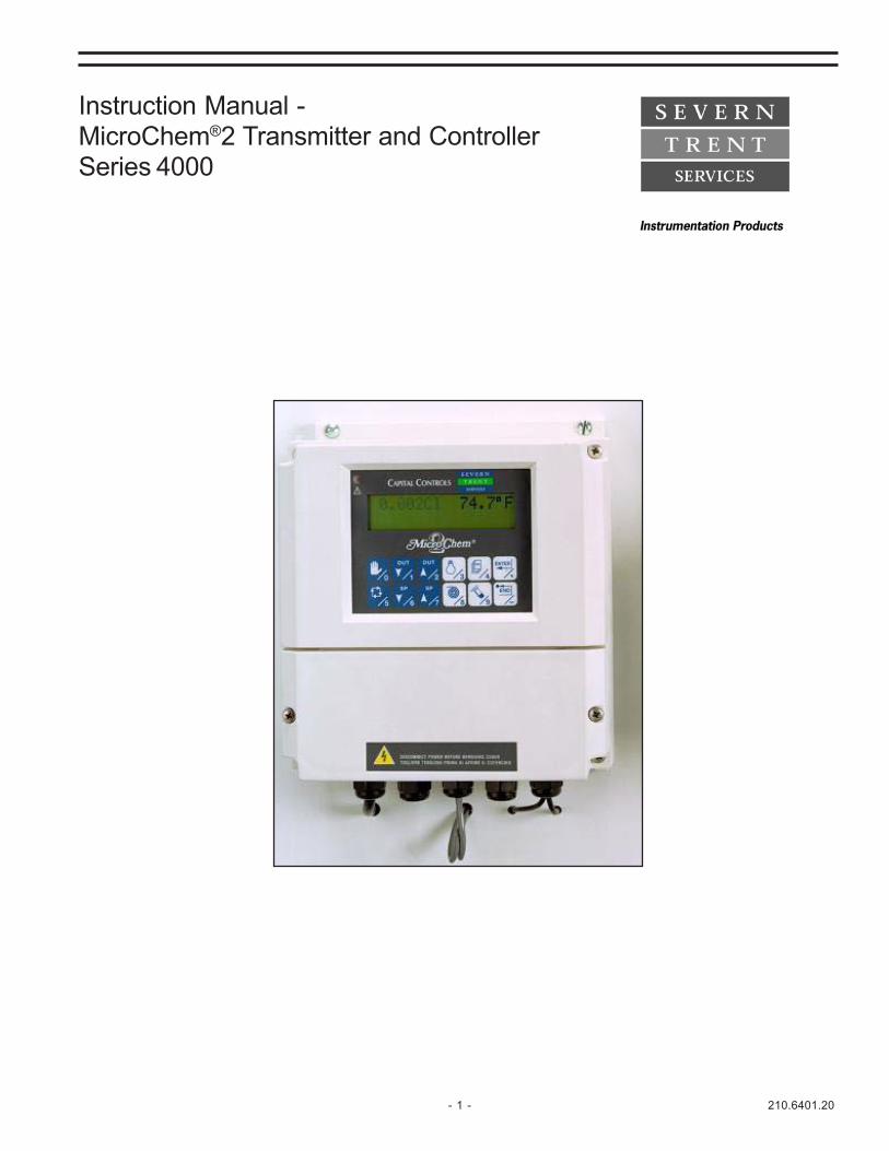
Instruction Manual -MicroChem®2 Transmitter and ControllerSeries 4000
210.6401.20 - 2 -
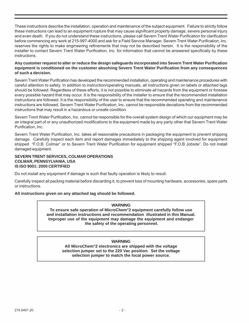
These instructions describe the installation, operation and maintenance of the subject equipment. Failure to strictly followthese instructions can lead to an equipment rupture that may cause significant property damage, severe personal injuryand even death. If you do not understand these instructions, please call Severn Trent Water Purification for clarificationbefore commencing any work at 215-997-4000 and ask for a Field Service Manager. Severn Trent Water Purification, Inc.reserves the rights to make engineering refinements that may not be described herein. It is the responsibility of theinstaller to contact Severn Trent Water Purification, Inc. for information that cannot be answered specifically by theseinstructions.
Any customer request to alter or reduce the design safeguards incorporated into Severn Trent Water Purificationequipment is conditioned on the customer absolving Severn Trent Water Purification from any consequencesof such a decision.
Severn Trent Water Purification has developed the recommended installation, operating and maintenance procedures withcareful attention to safety. In addition to instruction/operating manuals, all instructions given on labels or attached tagsshould be followed. Regardless of these efforts, it is not possible to eliminate all hazards from the equipment or foreseeevery possible hazard that may occur. It is the responsibility of the installer to ensure that the recommended installationinstructions are followed. It is the responsibility of the user to ensure that the recommended operating and maintenanceinstructions are followed. Severn Trent Water Purification, Inc. cannot be responsible deviations from the recommendedinstructions that may result in a hazardous or unsafe condition.
Severn Trent Water Purification, Inc. cannot be responsible for the overall system design of which our equipment may bean integral part of or any unauthorized modifications to the equipment made by any party other that Severn Trent WaterPurification, Inc.
Severn Trent Water Purification, Inc. takes all reasonable precautions in packaging the equipment to prevent shippingdamage. Carefully inspect each item and report damages immediately to the shipping agent involved for equipmentshipped “F.O.B. Colmar” or to Severn Trent Water Purification for equipment shipped “F.O.B Jobsite”. Do not installdamaged equipment.
SEVERN TRENT SERVICES, COLMAR OPERATIONSCOLMAR, PENNSYLVANIA, USAIS ISO 9001: 2000 CERTIFIED
Do not install any equipment if damage is such that faulty operation is likely to result.
Carefully inspect all packing material before discarding it, to prevent loss of mounting hardware, accessories, spare partsor instructions.
All instructions given on any attached tag should be followed.
WARNINGTo ensure safe operation of MicroChem®2 equipment carefully follow use
and installation instructions and recommendation illustrated in this Manual.Improper use of the equipment may damage the equipment and endanger
the safety of the operating personnel.
WARNINGAll MicroChem®2 electronics are shipped with the voltage
selection jumper set to the 220 Vac position. Set the voltageselection jumper to match the local power source.

- 3 - 210.6401.20
TABLE OF CONTENTS1 MODEL NUMBER BREAKDOWN........................................................................................ 62 INTRODUCTION ................................................................................................................... 8
2.1 Classification ............................................................................................................................................... 82.2 Parameters .................................................................................................................................................. 82.3 General Description ..................................................................................................................................... 92.4 Technical Specifications ............................................................................................................................... 92.5 Hardware structure of the system .............................................................................................................. 112.6 Instrument Operating Block Diagram ......................................................................................................... 13
3 INSTALLATION ................................................................................................................... 143.1 Dimensions and mounting ......................................................................................................................... 143.2 Mounting .................................................................................................................................................... 15
3.2.1 Wall mounting .............................................................................................................................. 153.3 Location ..................................................................................................................................................... 153.4 Electrical connections ............................................................................................................................... 16
3.4.1 Power supply p.c. board ............................................................................................................... 173.4.1.1 Power supply cable ........................................................................................................ 18
3.4.2 Digital I/O pc board ....................................................................................................................... 183.4.2.1 Digital Outputs ............................................................................................................... 183.4.2.2 Digital Inputs ................................................................................................................... 18
3.4.3 Analog input/output pc board ........................................................................................................ 183.4.3.1 Temperature compensation ............................................................................................. 19
3.4.4 Serial communication board ......................................................................................................... 193.4.5 Cable glands ................................................................................................................................. 19
4 SET-UP AND CONFIGURATION ........................................................................................ 204.1 Keyboard functionality ............................................................................................................................... 204.2 Display ..................................................................................................................................................... 224.3 Channel definition ...................................................................................................................................... 234.4 Set-up menu .............................................................................................................................................. 25
4.4.1 Configuration ................................................................................................................................. 264.4.1.1 Configuration parameters ................................................................................................ 264.4.1.2 Configuration menu flowchart .......................................................................................... 284.4.1.3 Cleaning functionality ...................................................................................................... 294.4.1.4 Instrument test ............................................................................................................... 30
4.4.2 Output Settings ............................................................................................................................ 324.4.2.1 Output signal modification 4-20 to 0-20 ......................................................................... 33
4.4.3 Alarms .......................................................................................................................................... 344.4.3.1 Alarm Display ................................................................................................................. 344.4.3.2 Alarm Setting Menu ........................................................................................................ 35
5 FUNCTIONALITY ................................................................................................................ 365.1 Transmitter ................................................................................................................................................ 365.2 Controller ................................................................................................................................................... 36
5.2.1 General description ....................................................................................................................... 375.2.2 Controller’s Parameters ................................................................................................................ 37
5.2.2.1 PID Parameters .............................................................................................................. 395.2.2.2 Feed Forward (FF) Configuration .................................................................................... 425.2.2.3 Compound Loop Controller ............................................................................................. 445.2.2.4 Time Sampling or Flow Pacing Controller ....................................................................... 445.2.2.5 Squared Controller (pH Applications) .............................................................................. 465.2.2.6 Contacts Output Controller ............................................................................................. 47
5.2.3 Standard Controller ....................................................................................................................... 485.2.3.1 Std Controller Display ..................................................................................................... 485.2.3.2 Std Controller Analog Output assignment ....................................................................... 495.2.3.3 Std Controller Digital Input assignment ........................................................................... 495.2.3.4 Std Controller Digital Output assignment ........................................................................ 50

210.6401.20 - 4 -
5.2.4 Averaging Controller ..................................................................................................................... 525.2.4.1 Averaging Controller Display .......................................................................................... 525.2.4.2 Averaging Controller Digital Input assignment ................................................................ 525.2.4.3 Averaging Controller Analog Output assignment ............................................................ 535.2.4.4 Averaging Controller Digital Output assignment ............................................................. 53
5.2.5 Swimming Pool Controller ............................................................................................................ 545.2.5.1 Swimming Pool Controller Display ................................................................................. 545.2.5.2 Swimming Pool Controller Analog Output assignment ................................................... 545.2.5.3 Swimming Pool Controller Digital Input assignment ....................................................... 555.2.5.4 Swimming Pool Controller Digital Output assignment .................................................... 55
6 CALIBRATION.................................................................................................................... 566.1 Calibration Procedure ............................................................................................................................... 56
6.1.1 Calibration Menu .......................................................................................................................... 566.1.2 Calibration Menu Flow Chart ........................................................................................................ 576.1.3 pH Sensor Calibration .................................................................................................................. 57
6.1.3.1 Double point calibration ................................................................................................. 576.1.3.2 Single point calibration (S.P.C.) ..................................................................................... 58
6.1.4 ORP Sensor Calibration ............................................................................................................... 596.1.4.1 “OXIDATION potential with NEGATIVE values” arrangement .......................................... 606.1.4.2 “OXIDATION potential with POSITIVE values” arrangement ............................................ 60
6.1.5 Chlorine/Chlorine Dioxide/Ozone/Bromine ................................................................................... 606.1.6 Dissolved oxygen calibration ........................................................................................................ 62
6.1.6.1 Calibration in water ........................................................................................................ 626.1.6.2 Calibration in air .............................................................................................................. 63
6.1.7 Fluoride ........................................................................................................................................ 656.1.8 Calibration of Sensors with a mA input ......................................................................................... 66
7 START UP .......................................................................................................................... 677.1 Preliminary operations .............................................................................................................................. 67
7.1.1 Getting started ............................................................................................................................. 677.1.2 Personalization of Parameters ..................................................................................................... 67
7.2 Controller PID tuning ................................................................................................................................. 68
8 MAINTENANCE ................................................................................................................. 698.1 Periodical operations ........................................................................................................................................ 69
8.1.1 Automatic sensitivity check during dual point calibration ............................................................. 698.1.2 Sensor signal check .................................................................................................................... 69
9 ERROR MESSAGES & TROUBLESHOOTING ................................................................ 709.1 Messages ................................................................................................................................................. 70
9.1.1 Operation messages .................................................................................................................... 709.1.2 Error messages ........................................................................................................................... 709.1.3 Alarms page ................................................................................................................................ 71
10 PARTS LISTS..................................................................................................................... 7210.1 MicroChem2 Assembly ............................................................................................................................. 7210.2 Dechlorinating Filter .................................................................................................................................. 74
11 SERIAL COMMUNICATION ............................................................................................... 7611.1 Standard of Communications .................................................................................................................... 76
11.1.1 Software characteristics .............................................................................................................. 7611.1.2 Communication Protocol .............................................................................................................. 7611.1.3 Message Types and Commands Description ............................................................................... 77
11.2 Communication Transaction Examples ..................................................................................................... 7811.2.1 Transaction A Example ................................................................................................................ 7811.2.2 Transaction B Example ................................................................................................................ 78
11.3 Serial link signal connection ..................................................................................................................... 78

- 5 - 210.6401.20
11.4 Datalink Terminator ................................................................................................................................... 7911.5 MicroChem®2 Memory Map ..................................................................................................................... 80
12 APPENDICES .................................................................................................................... 8312.1 EC Declaration ......................................................................................................................................... 83
Step by Step Simplified Instructions for Setting up and running the instrument ................................................. 84
A Standard Software Menu Tree ................................................................................................................... 98 B Controller Software Menu Tree ................................................................................................................ 100 C Swimming Pool Aeration Basin Controller ............................................................................................... 102
LIST OF FIGURES1 MicroChem®2 dimensions ................................................................................................................................. 142 Typical Wall-mounting Installations of MicroChem®2 ......................................................................................... 153 Series 4000 MicroChem®2 Transmitter/Controller Wiring Diagram .................................................................... 164 Jumper position for the power supply selection ................................................................................................. 175 Recommended use of cable glands .................................................................................................................. 196 Example of menus navigation ........................................................................................................................... 227 Connection of solenoid valves ........................................................................................................................... 308 Jumper position for 4-20 to 0-20 mA output signal modification ......................................................................... 339 HI and LO alarm dead band .............................................................................................................................. 3410 PID Parameters ................................................................................................................................................ 3911 Feed Forward Configuration .............................................................................................................................. 4212 Compound Loop Controller ................................................................................................................................ 4413 Time Sampling or Flow Pacing Controller .......................................................................................................... 4614 Error versus control band .................................................................................................................................. 4615 pH Calibration curves examples ........................................................................................................................ 5916 MicroChem®2 Assembly, Exploded View ......................................................................................................... 7217 Dechlorinating Filter .......................................................................................................................................... 7418 RJ11 Cable Pin Designation .............................................................................................................................. 7919 RJ11 Connector and Data Link Terminator layout .............................................................................................. 79
Please refer to the menu trees in the appendices for an overview of how tonavigate through the software.
Step by Step simplified instructions for setting up and running the instrument arefound in the appendix.
210.6401.20 - 6 -
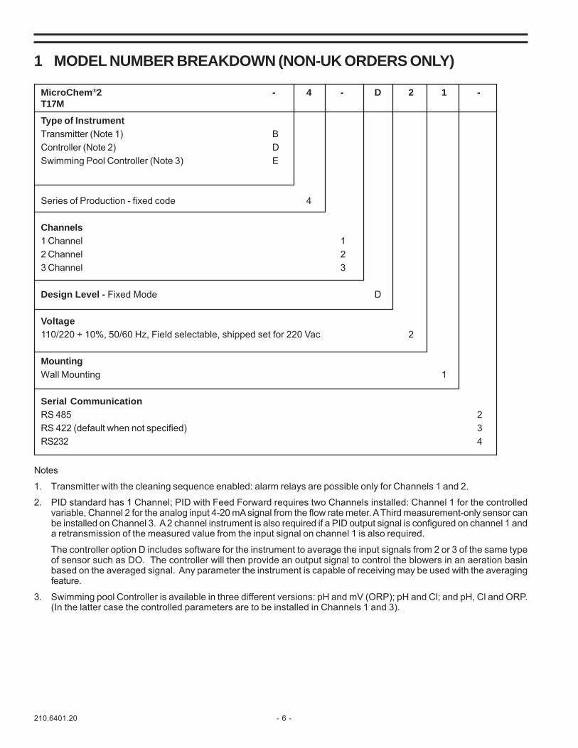
1 MODEL NUMBER BREAKDOWN (NON-UK ORDERS ONLY)
MicroChem®2 - 4 - D 2 1 -T17M
Type of InstrumentTransmitter (Note 1) BController (Note 2) DSwimming Pool Controller (Note 3) E
Series of Production - fixed code 4
Channels1 Channel 12 Channel 23 Channel 3
Design Level - Fixed Mode D
Voltage110/220 + 10%, 50/60 Hz, Field selectable, shipped set for 220 Vac 2
MountingWall Mounting 1
Serial CommunicationRS 485 2RS 422 (default when not specified) 3RS232 4
Notes
1. Transmitter with the cleaning sequence enabled: alarm relays are possible only for Channels 1 and 2.
2. PID standard has 1 Channel; PID with Feed Forward requires two Channels installed: Channel 1 for the controlledvariable, Channel 2 for the analog input 4-20 mA signal from the flow rate meter. A Third measurement-only sensor canbe installed on Channel 3. A 2 channel instrument is also required if a PID output signal is configured on channel 1 anda retransmission of the measured value from the input signal on channel 1 is also required.
The controller option D includes software for the instrument to average the input signals from 2 or 3 of the same typeof sensor such as DO. The controller will then provide an output signal to control the blowers in an aeration basinbased on the averaged signal. Any parameter the instrument is capable of receiving may be used with the averagingfeature.
3. Swimming pool Controller is available in three different versions: pH and mV (ORP); pH and Cl; and pH, Cl and ORP.(In the latter case the controlled parameters are to be installed in Channels 1 and 3).

- 7 - 210.6401.20
MODEL NUMBER BREAKDOWN (UK ORDERS ONLY)
noitpircseD rebmuNtraP
mehCorciM MT lennahC1-rettimsnarT2 5404-10
mehCorciM MT lennahC2-rettimsnarT2 0504-10
mehCorciM MT lennahC3-rettimsnarT2 4204-10
MicroChem®2 Transmitter1
noitpircseD rebmuNtraP
mehCorciM MT lennahC1-rellortnoC2 3104-10
mehCorciM MT lennahC2-rellortnoC2 5104-10
mehCorciM MT lennahC3-rellortnoC2 6104-10
MicroChem®2 Controller 2
noitpircseD rebmuNtraP
mehCorciM MT rellortnoClooPgnimmiwS2 3 lennahC2sadeilppuS- 1504-10
mehCorciM MT rellortnoCnisaBnoitareA2 4 lennahC2sadeilppuS- 2504-10
MicroChem®2 Specific Controllers
noitpircseD rebmuNtraP
10U730B426T1-gnitnuomllawrof-ylbmessAedahsnuS 5504-10
30U730B426T1-gnitnuomepiP"2rof-ylbmessAedahsnuS 6504-10
draoBeugolanA0004S 0004-17
MicroChem®2 Accessories
Note:1
Supplied with software to initiate a sensor cleaning sequence activated by a relay.Available with 1, 2 or 3 channels. When cleaning sequence is selected, alarm transmission is limited to channel 1 and channel 2 only.Relays are available for alarm transmission for channel 3 only if a cleaning sequence is not activated.
2 Combines a PID algorithm utilizing the sensor input signal or PID with Feed Forward control utilizing a 4-20mA input signal from a flowtransmitter (channel 2). Control is achieved through a 4-20mA output or time proportional relay.Available with 2 or 3 channels (only Channel 1 is for control).
3 Combines 2 PID control algorithms to control a swimming pool. pH is controlled on channel 1, ORP or Chlorine is controlled on a secondchannel. A third channel, in this case channel 2, can be used for ORP or chlorine not controlled on a channel 3.Supplied as standard with 2 channels, a third channel is available if ordered with a S4000 Analogue Board P/N 71-4000.
4 Specifically designed for O2 control. Signals from up to three DO sensors are averaged and computed, and then processed through aPID algorithm.Supplied as standard with 2 channels, a third channel is available if ordered with a S4000 Analogue Board P/N 71-4000.

210.6401.20 - 8 -
2 INTRODUCTION2.1 Classification
According to EN61010-1 MicroChem®2 is classified as• electrical equipment for measurement and test• electrical equipment for process control• electrical equipment designed to be safe at least in the following conditions:• altitude lower than 6550 feet (2000 m)• operation temperature limits 15°F to 130°F (-10 to +55 °C)• storage temperature limits - 40°F to 150°F (-40 to +65 °C)• maximum relative humidity: 80% with temperature up to 88°F (31°C), with linear decrease down to 50% with
temperature 104°F (40 °C)• supply voltage allowed variations: 115 or 230 Vac ± 10 %• overvoltage class (installation class): II• pollution degree: 2
2.2 ParametersPARAMETER SYMBOL NOTE 1: Fluoride is available in units that arepH pH running software version 2.7 or higher. To addORP (oxidation reduction potential) mV software version 2.8 to existing MicroChem®2Dissolved Oxygen O2 transmitters, upgrade board #1T686B128U06Residual Chlorine Cl is available.Chlorine Dioxide CDOzone C3 NOTE 2: Chlorine and conductivity probes are availableTemperature T in units running software version 2.8 or higher andFluoride F containing the expanded function board.Bromine Br (1T686B129U03, U04, U05)Conductivity* mA
These symbols are also used in displayed indications.
*Sensors with a 4-20mA output can be fed into the MicroChem®2 and the signal displayed as either mA or for certain common sensors converted into actual units e.g. conductivity (μS). A list of the configurable units available is shown below:
Symbol UnitmA Milliamp% Percentppm parts per millionmg/l milligrams per litergr/h grams per hourl/s liters per secondl/h liters per hourm3/h meter cubed per hour°C degrees centigrade°F degrees FahrenheitμS micro siemensmS milli siemensKPa KilopascalsMPa MegapascalsPSI Pounds per square inchGPM Gallons per minuteGPD Gallons per dayMGD Mega gallons per dayNTU Nephelometric unitsFTU Formazin turbidity unitsm metersft feetIn inches

- 9 - 210.6401.20
2.3 General DescriptionMicroChem®2 Analyzer/Controller Family includes 3 types of instruments. Each type, except Type 3, canmeasure the following parameters: conductivity, pH, ORP, (oxidation reduction potential), dissolved oxygen,chlorine, chlorine dioxide, ozone, bromine, conductivity, fluoride, mA and temperature. Instruments Type 1 andType 2 can accept any combination of these parameters.
- Transmitter (Instrument Type 1)Transmitters, single, dual or three channel.
- Controller (Instrument Type 2)PID controller for the installed Sensor, with specific algorithms for each type of measured parameter. Itcan accept an optional 4-20 mA signal from a flowmeter on channel 2. This second input can be used asFeed Forward input in the PID algorithm.
- Averaging ControllerSupports either two or three probes. The instrument calculates the average value based on two/threeinput signals, feeds it to the PID as the process variable, and generates a 4-20 mA analog output controlsignal or a digital output control signal (contacts closure).
- Swimming Pool Controller (Instrument Type 3)Available in three different parameter combinations:- three channels (pH, mV, Cl),- two channels (pH and mV),- two channels (pH and Cl).It performs PID control of two channels: pH (on channel 1) and the sensor installed on channel 2 (whenconfigured as a 2 channel instrument) or on channel 3 (when configured as a 3 channel instrument).
2.4 Technical Specifications- Display: digital LCD display, dot matrix, 2-line x 16 characters, with back light.- Power supply, selectable through a jumper on the power supply pc board. (see Sect. 3.4.1):
110 Vac, ±10%, 50/60 Hz220 Vac, ±10%, 50/60 HzNote: All units shipped 220 Vac
- Maximum consumption: 20 VA- Electrical classification: for non hazardous area- Enclosure classification: NEMA 4, IP65, suitable for outdoor mounting- Housing construction material: plastic, Goodlac V0 532 ULSD F17 self extinguishing tested according UL 94 and classified V0 (material ABS plus 17% fiberglass)- Mounting hardware is supplied- Analog outputs: one for each installed channel (analog I/O pc board); separately selectable for each
channel as 0-20 mA or 4-20 mA (to be specified in the order).- Outputs are galvanically separated from inputs. Load 0-1000 ohms, protected against short circuits.- Relay Outputs. Rating: 120/240 VAC/125 VDC @8 A max. Relay contacts can be configured as NO or
NC in the configuration menu.- Serial communication port: RS232, RS422 and RS485 with RJ11 plug-in sockets and 9-pin terminal.
The protocol used is illustrated in a dedicated section at the end of this manual.- Alarm level setting: High and Low alarm for channels 2 or 3. Separate levels for each channel are field
selectable. Dead band freely selectable for each channel.- Measuring ranges: field selectable for each channel within the limits indicated for each parameter, as
follows:PARAMETER MINIMUM SPAN MAXIMUM RANGE DEFAULT SETTING RANGEpH 1.00 pH 0.00 to 14.00 pH 2.00 to 12.00 pHmV 100 mV -1500 to +1500 mV -500 to +500 mVO2 2.0 ppm 0.00 to 20.00 ppm 0.00 to 10.00 ppmO3 0.25 ppm 0.00 to 10.00 ppm 0.00 to 1.00 ppmCl 0.25 ppm 0.00 to 10.00 ppm 0.00 to 1.00 ppmCD 0.25 ppm 0.00 to 10.00 ppm 0.00 to 1.00 ppmT 5 °C 0 to +100 °C 0 to +100 °CmA 2 mA 0/4 to 20 mA 4 to 20 mAF 0.25 ppm 0 to 9999 ppm 0 to 10 ppmBr 0.25 ppm 0 to 10.00 ppm 0 to 1.00 ppmORP 100 mV -1500 to +1500 mV -500 to +500 mVμS +/- 5% of probe range 0 to 10,000 μS 4 - 20 μS
210.6401.20 - 10 -
Sensors with a 4 to 20 mA output can be attached to the transmitter, the units and range set and then thesensor output can be displayed on the screen.
• Weight: 6.6 lbs (3 kg)• Outline dimensions: 8.6" x 10" x 4.8" (220 mm x 250 mm x 120 mm.) See Fig.1 for detailed outline
dimensions• Ambient temperature limits for stocking: -40°F to +150°F (-40°C to +65°C)• Ambient temperature limits during operation: 15°F to +130°F (-10°C to +50°C)• If the instrument is expected to be installed in the sunlight, the optional sunshade protection is strongly
recommended)• Thermal drift: within 0.2% of full scale for a 130°F (10°C) temperature variation.• Relative humidity: 80% with temperature up to 88°F (31°C), with linear decrease down to 50% with
temperature 104°F (40 °C).• Accuracy: within ± 0.2 % of full scale.• Repeatability: 0.05% of span• Stability: 0.05% of span• Transmitter response time: measurement is refreshed at each microprocessor scan cycle (100 msec)• Microprocessor scan cycle: 100 msec• Smoothing: separately set for each channel inside Configuration menu.• Memory: non-volatile
- 11 - 210.6401.20
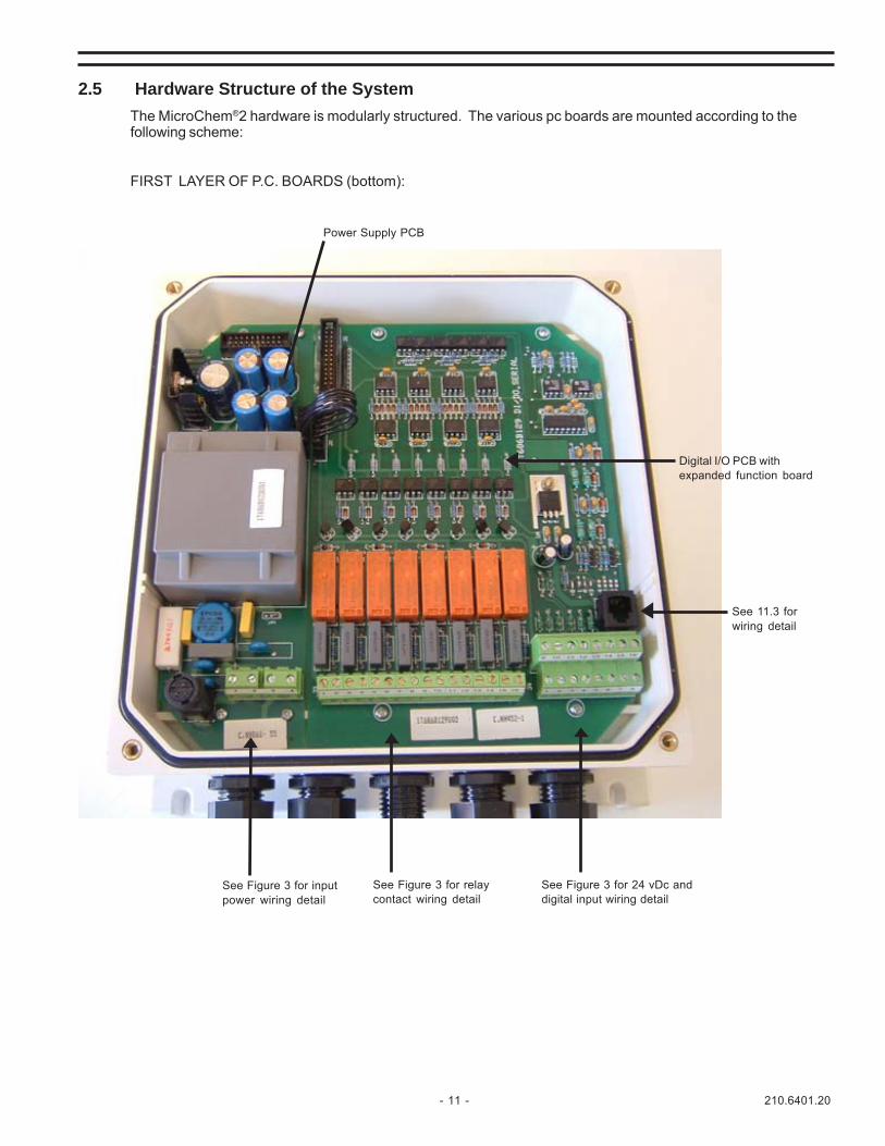
2.5 Hardware Structure of the SystemThe MicroChem®2 hardware is modularly structured. The various pc boards are mounted according to thefollowing scheme:
FIRST LAYER OF P.C. BOARDS (bottom):
Power Supply PCB
Digital I/O PCB withexpanded function board
See 11.3 forwiring detail
See Figure 3 for 24 vDc anddigital input wiring detail
See Figure 3 for relaycontact wiring detail
See Figure 3 for inputpower wiring detail
210.6401.20 - 12 -
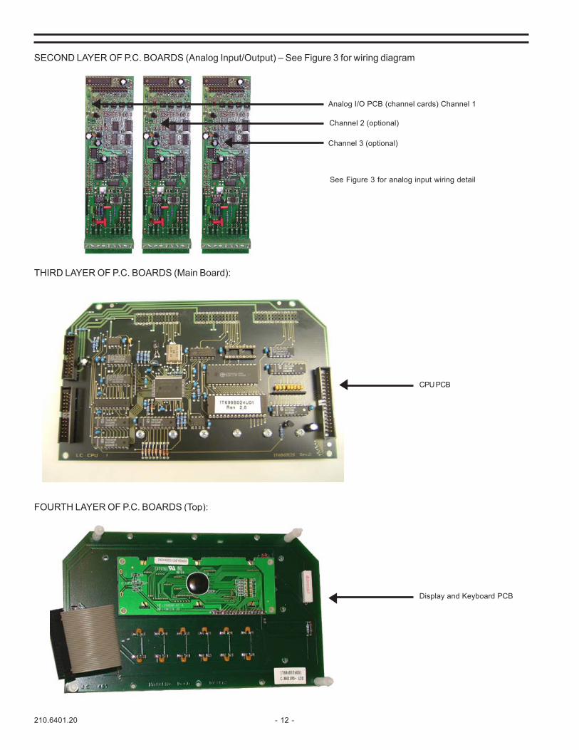
SECOND LAYER OF P.C. BOARDS (Analog Input/Output) – See Figure 3 for wiring diagram
Analog I/O PCB (channel cards) Channel 1
Channel 2 (optional)
Channel 3 (optional)
CPU PCB
Display and Keyboard PCB
See Figure 3 for analog input wiring detail
THIRD LAYER OF P.C. BOARDS (Main Board):
FOURTH LAYER OF P.C. BOARDS (Top):

- 13 - 210.6401.20
Power Supply
ANALOG I/O PCB 1Inputs: Chlorine
Chlorine DioxideOzoneBrominepHORP (mV)TempDissolved OxygenmAFluoride
Output: 4-20mA
ANALOG I/O PCB 2Inputs: Chlorine
Chlorine DioxideOzoneBrominepHORP (mV)TempDissolved OxygenmAFluoride
Output: 4-20mA
ANALOG I/O PCB 3Inputs: Chlorine
Chlorine DioxideOzoneBrominepHORP (mV)TempDissolved OxygenmAFluoride
Output: 4-20mA
Display&
KeypadPCB
Digital I/O ExpandedFunction Board
CCO1CCO2CCO3CCO4CCO5CCO6CCO7CCl 1 Freezes Channel 1CCl2 Freezes Channel 2
When CCl OR is selectedEither CCl 1 or CCl 2 will FreezeChannels 1, 2 and 3.
RS232RS485RS422
CPU PCB
Functionsdepend on
type ofinstrumentselected
Watch Dog
2.6 Instrument Operating Block Diagram

210.6401.20 - 14 -
3 INSTALLATION
3.1 Dimensions and Mounting
Figure 1 - MicroChem®2 Dimensions
WARNING
When installing MicroChem®2 Outdoors, the use of sunshadeis strongly recommended.

- 15 - 210.6401.20
3.2 Mounting3.2.1 Wall Mounting
Figure 2 - Typical Wall Mounting Installations of MicroChem®2
3.3 LocationThe transmitter location should meet the following:- the installation site should be free of vibrations- atmosphere should be free of corrosive substances- ensure sufficient space to allow easy operation and maintenance- mount the transmitter at eye level- a sunshade is strongly recommended when installed outdoors- confirm that the power source agrees with the power requirements detailed on the instrument tag

210.6401.20 - 16 -
3.4 Electrical Connections
Figu
re 3
- Se
ries
4000
Mic
roC
hem
®2
Tran
smitt
er/C
ontro
ller W
iring
Dia
gram

- 17 - 210.6401.20
3.4.1 Power supply p.c. board
The power supply is connected to the terminal board TB1. See Figure 3.
The MicroChem®2 is shipped with the input voltage jumper set to 220 Vac. The selection between the110 Vac or 220 Vac power settings can be changed by moving a jumper (in position JP1) on the power supplypc board. See Figure 4 to change the jumper setting.
1. disconnect the power supply to the instrument.2. open the upper enclosed cover3. move the jumper to the correct position4. close the cover and reconnect the power
Figure 4 - Power supply jumper position 110 Vac or 220 Vac
Power Supply PCB - reverse sidejumper set for 110 Vac
Jumper set for 220 Vac

210.6401.20 - 18 -
3.4.1.1 Power supply cablePower supply cable has to be supplied by the customer. In accordance to EN61010-1 powersupply cable has to satisfy the following requirements:
· power supply cable must be certified (e.g. IMQ, UL, CSA...) or approved by an officialnational testing bureau. Alternatively, the cable should meet IEC 227 and IEC 245requirements.
· 16 AWG (1 mm2 or 1.5 mm2) three-conductor cable shall be used· Cable glands must be suitable for cables with 6 to 10 mm diameter and assure IP 68
sealing.· the cable must include a ground conductor and be properly grounded.
DANGERElectrical shock hazard. Power supply cables are
connected to 110 or 220 Vac voltage.Local codes must be complied with
when installing the equipment
3.4.2 Digital I/O Expanded Function Board3.4.2.1 Digital Outputs
MicroChem®2 digital outputs are provided by seven (7) SPST relay contacts which are fieldselectable for normally closed (NC) or normally open (NO) operation.
The function of each output contact depends on the type of instrument selected and itsconfiguration. The different possibilities are detailed in the sections dedicated to each specifictype of instrument, as detailed under each specific instrument section.
Figure 3 shows how the terminal number assigned to each output relay contact (CCO) on theI/O pc board.
CAUTIONAny valve or device connected to MicroChem®2 contact
outputs must be wired in order to be fail safe.
3.4.2.2 Digital InputsMicroChem®2 digital input contacts (CCI) are represented in Figure 3. The cable used for thedigital inputs should be:
· 18 AWG (0.5 - 1.0 mm2) two-conductor with shield.· The shield must be connected to the ground shield terminal strip inside the MicroChem®2.
3.4.3 Analog input/output pc boardRefer to each sensor instruction manual for the color/number codification for the sensors wires. ThePt100 shield and the sensor shield, if present, must be connected to ground shield terminal strip, insidethe MicroChem®2. Please notice that, for pH, ORP and O2 sensors it is recommended to fix the cablenear the sensor preventing any wear that might occur if the cable were to move at the outlet of the cablegland.
The 0-20 mA or 4-20 mA signal INPUT is on terminals 5 and 6: when these terminals are used for the 0/4-20 mA INPUT, such as a flow meter for feed forward or compound loop control, install a 100 ohms resistor(0.1 % accuracy) across terminals 5 and 6. Please refer to Section 3.3, Figure 3.
Sensors with a 4 to 20 mA output can be attached to the transmitter by attaching the sensor to pins 5 and6 with a 100 ohm resistor across the terminals. The units and range can be set within the channelconfiguration software and then the sensor output can be displayed on the screen – see section 2.2 forthe range of units that can be selected.
Note: The Cl4000 and conductivity probe cables 78-4001, 2 and 3 have a resistor built in to the lead sodo not require a further resistor.
Use 18 AWG (0.5 - 1.0 mm2) shielded twisted pair cables for 4-20 mA output signals and connect shieldsto the shield ground terminal strip inside the MicroChem®2. See Figure 3.

- 19 - 210.6401.20
3.4.3.1 Temperature compensationThe temperature compensation (Pt100) is not necessarily present in each sensor, in fact insome installations the different sensors are installed in the same cell, and therefore thereference temperature can be read from one input only, namely from the sensor connected tochannel 1.
When configuring channel 2 and 3 from the installation menu, after the choice of the type ofsensor, the reference temperature source is requested. Choose “equal to first” if the referencetemperature for that channel is taken from channel 1 or “independent” if the temperaturecompensation for the channel is provided from another input source. This option is notapplicable for mA and ORP inputs measurements, as these parameters are not influenced byoperating temperature.
3.4.4 Serial communication boardMicroChem®2 supports serial communication using the modular telephone jack RJ11 connector. The pin-outsof the RJ11 connector is illustrated in Section 11.3 in this manual, dealing with the serial communicationoption.
3.4.5 Cable glandsThe enclosure has 9 pre-formed conduit entries for wiring. Five of them have been opened and made ready for usein the factory.
The MicroChem®2 fully wired is connected as follows (Figure 5):· 1 three-conductor power cable· sensor cables· 4-20 mA output cables· wires for digital outputs (CCO 1-7)· 2 two-conductor cable for digital inputs (CCI 1-2)· 1 three-conductor cable for serial link (or cable with modular telephone jack RJ11 type)
When wiring the MicroChem®2, the following wiring recommendations must be followed:· never run cable for power supply with other cables· never run analog I/O cables with other cables· never run relay cables or wires with other cables
Figure 5 - Recommended use of cable glands

210.6401.20 - 20 -
4 SET-UP AND CONFIGURATION4.1 Keyboard functionality
All the keys have a primary and secondary function, except the ENTER key. The second function on the keyswith a blue background is used in Controllers options (instrument Type D, Type E and Type F). The instrumentautomatically recognizes the selection between numbers and functions.
yeK noitcnuFyramirP noitcnuFyradnoceS
ROTCELESLAUNAM.)F,E,DepyTstnemurtsni(srellortnoCniedomlaunamstceleS dewollanehworeztigid:0
TUPTUOESAERCEDninehw)F,E,Dstnemurtsni(rellortnoCnituptuoesaerceD
.edomlaunamdewollanehw1tigid:1
TUPTUOESAERCNIninehw)F,E,DepyTstnemurtsni(rellortnoCnituptuosesaeercnI
.edomlaunamdewollanehw2tigid:2
THGILnwod.pulortnocssenthgirbyalpsiD dewollanehw3tigid:3
UNEM.sretemarapehthguorhtselcycdnaunemehtsyalpiD dewollanehw4tigid:4
tigniriuqerretemarapyna,desutonsitnioplamicedehT:RETNE.noitisoptcerrocehtnitnioplamicedehtsedulcniydaerla
A..retemarapdeyalpsidehtotegnahcaselbane:noitcnufretnEehtnosraepparosrucehtnehw)tes(degnahcebnacretemarap
ehttonrorehtehw,deraeppasahrosrucehtecnO.yalpsidotdesserpebtsumyekretnEeht,degnahcneebsahretemarap
.eulavdeyalpsidehtmrifnoc
sgninraWehtpusgnirbyekretnEehtedomgnitarepoehtnI.egapsegasseM&
enoN
ROTCELESCITAMOTUAstnemurtsni(srellortnoCniedomnoitarepocitamotuAstceleS
.)E,DepyTdewollanehw5stigid:5

- 21 - 210.6401.20
Table 1 - Keyboard functionality
yeK noitcnuFyramirP noitcnuFyradnoceS
WORRANWODTNIOPTES.)E,DepyTstnemurtsni(srellortnoCnitnioPteSsesaerceD dewollanehw6tigid:6
WORRAPUTNIOPTES.)E,DepyTstnemurtsni(srellortnoCnitnioPteSsesaercnI dewollanehw7tigid:7
HSAWdnadetaivitcasinoitposihtnehwecneuqesgninaelcastratS
.)orezmorftnereffideulavynatatessremit(dewolladewollanehw8tigid:8
LECNACtnemurtsniehtrewop(sretemaraptluafeddaolotdesusilecnaC
)desserpyeklecnaCehtgnipeekelihwputirewopdnanwod
deretnesawtahtretemaraparaelcotdesuoslasilecnaCsraepparosrucehtdeifidomebnacretemarapanehw;yltcerrocni,thgirehtnonoitisoptsalehtnisirosrucehtnehW.yalpsidehtnodnaeulavdecudortniylwenehteteledlliwyeklecnaCehtgnisserp
.deretneebotenowenawolla
dewollanehw9tigid:9
DNEnruterdnaunemaroretemarapatixeotdesserpsiyekdnEehT
nehwunemehthguorhtpusecnavdayeksihT..unemreppuot.noitareponinehwsegaptnereffidsllorcsdnagnitixe
dewollanehwngisevitagen:-
210.6401.20 - 22 -
1 0 . 1 2 p H 1 0 . 4 ° C
1 2 . 0 0 S P 1 6 O U T % A
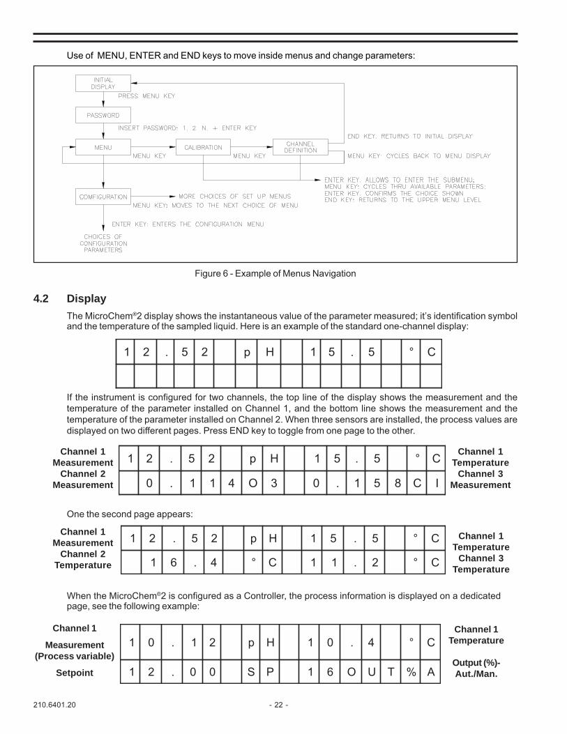
When the MicroChem®2 is configured as a Controller, the process information is displayed on a dedicatedpage, see the following example:
Channel 1
Measurement(Process variable)
Setpoint
Channel 1Temperature
Output (%)-Aut./Man.
If the instrument is configured for two channels, the top line of the display shows the measurement and thetemperature of the parameter installed on Channel 1, and the bottom line shows the measurement and thetemperature of the parameter installed on Channel 2. When three sensors are installed, the process values aredisplayed on two different pages. Press END key to toggle from one page to the other.
One the second page appears:
Use of MENU, ENTER and END keys to move inside menus and change parameters:
Figure 6 - Example of Menus Navigation
4.2 DisplayThe MicroChem®2 display shows the instantaneous value of the parameter measured; it’s identification symboland the temperature of the sampled liquid. Here is an example of the standard one-channel display:
1 2 . 5 2 p H 1 5 . 5 ° C
1 2 . 5 2 p H 1 5 . 5 ° C
0 . 1 1 4 O 3 0 . 1 5 8 C I
1 2 . 5 2 p H 1 5 . 5 ° C
1 6 . 4 ° C 1 1 . 2 ° C
Channel 1Measurement
Channel 2Measurement
Channel 1Measurement
Channel 2Temperature
Channel 1Temperature
Channel 3Measurement
Channel 1Temperature
Channel 3Temperature

- 23 - 210.6401.20
4.3 Channel Definition - This menu allows to select the type of sensor associated to each Channel:
Please refer to the menu trees in the appendices for an overview of how to navigate through the software.

210.6401.20 - 24 -
4.3 Channel Definition - (continued)
Notes:1. When changing channel definition from one parameter to another, the MicroChem®2 transmitter/controller
will set the alarm outputs and the pid parameters to the default values.2. If chlorine (CL) is selected, the type of CL measurement must be defined as either a cell (KC4000) or a
probe (CL4000). When CL4000 probes are selected, you will be prompted to enter the (4mA and 20mA)probe settings to match the range of the probe supplied with the system (i.e. 0-2 or 0-10 ppm).
3. Sensors with a 4 to 20 mA output can be attached to the transmitter and the units and range can be setwithin the channel configuration software and then the sensor output can be displayed on the screen - seesection 2.2 for the range of units that can be selected.

- 25 - 210.6401.20
The Channel definition menus are displayed in accordance to the number of the channels installed (e.g. if onlyChannel 1 is installed, only Channel 1 definition menu appears; if two channels are installed, both Channel 1definition menu and Channel 2 definition menu will appear. The same principle applies for Channel 3).Select the type of channel according to the sensor installed (see parameter 2.2 for the symbols used).
NOTE: At power-up, the instrument loads data in memory according to the last channel definition.When the Channel definition is modified, in order to have the new data properly stored, it is necessaryto exit the Channel definition menu and return to the operation menu (END key), switch-off power to theinstrument, then power it up again while pressing key 9 (CANCEL).
4.3.1 Conductivity or 4-20mA Input SensorsThe conductivity probes 01-4047,8,9 and 01-4065 have a 4 to 20mA output that is fed into the 4-20mAinput of the MicroChem2 transmitter. To define the channel as conductivity or to define the units of a4-20mA input probe follow the preceding instructions and set the channel as mA. Like the CL4000, youwill be prompted to enter the 4mA and 20mA settings to match the range of the probe.
4.4 Set-up MenuThe set-up menu is structured in three different submenus:• Configuration to set the general operating parameters of the instrument, see 4.4.1;• Output settings to select 4-20 mA or 0-20 mA output for each channel, see 4.4.2;• Alarms to set alarm levels; see 4.4.3.Each of the submenus will be discussed in detail in the following pages.

210.6401.20 - 26 -
4.4.1 ConfigurationThe configuration menu conforms to the general parameters of the instrument. Only those parametersthat are pertinent to the selection made and to the hardware installed will appear in the menu. When adigital value is requested, pressing the ENTER key will cause a cursor to appear in the display: at thispoint a digital value may be entered using the second function of the keyboard push buttons. When theENTER key is pressed again, the value shown on the display will be confirmed.
A description of the configuration parameters appearing in the menu is detailed below. A summary ofthe configuration menu flowchart follows in the next page.
4.4.1.1 Configuration parametersLanguage: select the language of the displayed messages. Available languages:
Italian, English, French, German, Spanish.
Password: set the password, choose a numerical code composed of up to 5characters. Default setting by Factory: 00000
Serial link: optional serial communication link. See paragraph 11.0 “SerialCommunication” for detailed instructions
Cleaning: logical sequence for periodical cleaning of the sensors. See paragraph4.4.1.3 for details
Temperature Select measuring units for displayed temperature value: °C or °F;Select: default is °C.Temperature set: Defines the temperature to be used by the MicroChem®2. If the
thermistor is found to be faulty “RT FAULT” will appear on thedisplay.
Altitude: When at least one of the channels is O2. The altitude above sea levelmust be set at start up. Altitude is needed for automatic “in air”calibration procedure. Available units are feet (ft) and meter (m).Default Altitude is 200 m.
Please refer to the menu trees in the appendices for an overview of how to navigate through the software.

- 27 - 210.6401.20
CCI in ‘OR’: When MicroChem®2 is installed as a transmitter or controller andanother MicroChem®2 is driving the cleaning sequence for all thesensors installed on the transmitter or controller, the MicroChem®2that is not driving the cleaning needs to be “informed” that its sensorsare being cleaned: this information comes through its digital inputs(CCI) that are connected to the relay outputs (CCO) driving thecleaning on the other MicroChem®2. When “CCI in OR” option ischosen, if either or both the digital inputs (CCI) are closed theMicroChem®2 “knows” that it has to freeze the output signals. Seesection 5.2.3.3.
Average: For 2 or 3 channel transmitters with identical sensors installed, thetransmitter computes the average of the input signals. The choice isAverage NO or Average YES; default is NO (the average is notcomputed).
For 2 or 3 channel controllers when in the channel definition menu, ifthe second channel is like the first, then MicroChem®2 asks for “TX”or“PID” option. If TX is chosen, the second channel will stand alone andthe instrument will use only Ch1 for PID control. If “PID” is chosen,then the second and third channel’s measurement(s) will be used forthe average calculation and the PID will use the average value forregulation.
Delta: For dual channel transmitters with identical sensors on each channel;the transmitter displays an alarm when the difference between the twomeasured values is higher than the set value allowed for the deviation.Default = 0.0 (the delta is not active).
Smoothing: Smoothing or damping in seconds applied to the input signal lessensthe measurement fluctuation on the display. It can be set separatelyfor the three channels. Allowed values are 0.00 - 99.99. Default is1.00. Typically smoothing is set at 30.00.
Digital I/OSetting: Configure each digital input (CCI) and each relay output (CCO)
separately as normally closed (NC) or normally open (NO).Default is: NO
Instrument test: See paragraph 4.4.1.4

210.6401.20 - 28 -
4.4.1.2 Configuration menu flowchart
Please refer to the menu trees in the appendices foran overview of how to navigate through thesoftware.
Step by Step simplified instructions for setting upand running the instrument are found in theappendix.

- 29 - 210.6401.20
4.4.1.3 Cleaning functionalityThe cleaning functionality implemented in the MicroChem®2 supports a sequence of operationsnecessary to perform a periodical cleaning of the sensors. This function is always present in thesoftware and can be enabled or disabled by a YES/NO selection in the configuration menu(default setting is NO).
When the selection is set to “YES”, the instrument activates the cleaning sequence and operatesthe relay output contacts associated to CCO5 and CCO6 to drive the solenoid valves for thewashing and rinsing lines (see Fig. 7). When “YES” is selected, you are given a choice of A orB. Choose B. A refers to a previous cleaning sequence that is no longer available. Each phaseof the cleaning sequence requires a different timing, and this can be configured in parametersT1, T2, T3 and T4 (see table 3 below for details). During the cleaning sequence active phases,the measurement is frozen to the last valid value, and when the instrument is operating as aController, the latter is automatically forced in manual mode.
The cleaning sequence can be started locally with a manual command by pressing Key 8/WASHING, or it can be triggered automatically by setting proper values in the timers T1-T4.The cleaning sequence consists of the following four phases:
T1 - Analysis: Normal operation phase of the sensor, that is the time period betweenthe end of a cleaning sequence and the start of the next one inautomatic mode. Allowed time values are 1 sec. to 30 hours. Typicalvalue is 23.5 hours.
T2 – Washing: Phase to be used to wash the sensor with chemical detergent.Allowed values are 0-30 minutes. Typical value is 10 min.
T3 – Rinsing: Phase to be used to rinse the sensor with pressurized clean water.Allowed values are 0-30 minutes. Typical value is 10 min.
T4 – Pause: Pause period is the time allowed for the sensor to recover sensibilitybefore starting a new measure. Allowed values are 0-30 minutes.Typical value is 10 min.
Table 2 - Sequence of cleaning phases
LegendO = open••••• = closed
1. CCO5 and CCO6 must be configured in configuration menu as CCO5=NC and CCO6=NC
SESAHP EMIT 5OCC 1
)TNEGRETED(6OCC 1
)ESNIR( EGASSEM
sisylanA1T 1T ••••• •••••
gnihsaW2T 2T O ••••• !HSAW
gnisniR3T 3T ••••• O !HSAW
esuaP4T 4T ••••• ••••• !HSAW
sisylanA 1T ••••• •••••

210.6401.20 - 30 -
Figure 7 - Connection of solenoid valves
4.4.1.4 Instrument testThis submenu, which is part of the Configuration menu, is used to perform self-diagnostic routineson the MicroChem®2 basic functions, sensor check and MicroChem®2 electrical calibration.
Keyboard test: Pressing any key the display will show the corresponding number(0....9) or function (ENTER, END). To exit this submenu press ENDkey and keep it pressed for 3 seconds, until the display shows - - -.
Display test: Once entered the display shows all the available characterspresent in all the 32 writing locations of the display. To exit pressEND key.
Digital I/O: see Par. 4.4.1.4.1
Analog I/O: see Par. 4.4.1.4.2
Electrical Calibration I/O: see Par. 4.4.1.4.3
Please refer to the menu trees in the appendicies for an overview of how to navigate through the software.

- 31 - 210.6401.20
4.4.1.4.1 Digital I/O TestThis submenu allows to verify the status and the correct functionality of the digitalinputs and outputs:
Digital Input: Input signals submenu display shows:“ 1 2 ““ OFF OFF “
changing the status of one of the CCI by shorting the associated terminals (1-3 or2-4) causes the display to show ON below the number of the associated CCI.Digital Output: the display will show the status of the 7 relay output contacts:
“ 1 2 3 4 5 6 7 ““ 0 0 0 0 0 0 0 “
press the key corresponding to the displayed number (from 1 to 7) causes thedisplayed value to change from “0” to “1” or vice versa, and the output contact willbe changed accordingly from “OPEN” to “CLOSE”: verify with an ohmmeter thestatus of the relay output contacts (CCO) (see terminal numbers below).
Table 3 - CCO Terminal identification
4.4.1.4.2 Analog I/O Test
The Analog I/O test allows verification of the input and output signals.
In the analog “Input” mode, the display shows the value of the signal generated bythe sensor and the corresponding Pt100 thermistor.
In analog output mode the instrument provides a means to check the 0/4-20 mAoutput: By pressing the OUT increase and OUT decrease keys, the output can beforced and compared to a reading on a multimeter connected to the output terminals,terminals 1(-), 2(+).
)OCC(rebmuNtcatnoC 1OCC 2OCC 3OCC 4OCC 5OCC 6OCC 7OCC
noitacifitnedIlanimreT 1 2 3 4 5 6 7 8 9 01 11 21 31 41

210.6401.20 - 32 -
4.4.1.4.3 Electrical calibrationAccess to this menu is protected by a password that is only knownto Severn Trent Service personnel to prevent unintentional changes.The electrical calibration is only performed at the factory at the end ofmanufacturing process.
4.4.2 Output settingThe Output Settings menu allows to set current output (0-20 or 4-20 mA), zero (Out Zero) and full scale(Out Max) values, in engineering units. Out Zero value corresponds to 0 mA or 4 mA (according to theoutput chosen) and the Out Full Scale value to 20 mA.
WARNINGThe 0 or 4 mA selection is a hardware/software setting made during
manufacturing process. Set 0-20 mA or 4-20 mA accordingly. To modifyoutput signal change Jumper JP1-JP2 as shown in Par. 4.4.2.1 – Fig. 8
(See Par. 4.4 to get here)
- 33 - 210.6401.20
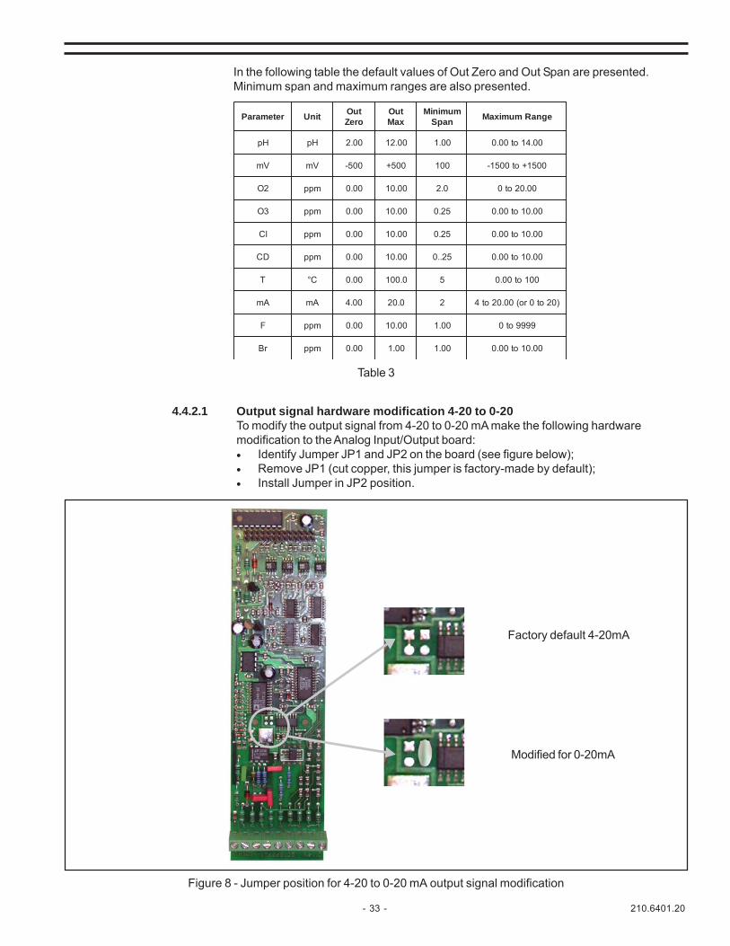
4.4.2.1 Output signal hardware modification 4-20 to 0-20To modify the output signal from 4-20 to 0-20 mA make the following hardwaremodification to the Analog Input/Output board:• Identify Jumper JP1 and JP2 on the board (see figure below);• Remove JP1 (cut copper, this jumper is factory-made by default);• Install Jumper in JP2 position.
retemaraP tinU tuOoreZ
tuOxaM
muminiMnapS egnaRmumixaM
Hp Hp 00.2 00.21 00.1 00.41ot00.0
Vm Vm 005- 005+ 001 0051+ot0051-
2O mpp 00.0 00.01 0.2 00.02ot0
3O mpp 00.0 00.01 52.0 00.01ot00.0
lC mpp 00.0 00.01 52.0 00.01ot00.0
DC mpp 00.0 00.01 52..0 00.01ot00.0
T C° 00.0 0.001 5 001ot00.0
Am Am 00.4 0.02 2 )02ot0ro(00.02ot4
F mpp 00.0 00.01 00.1 9999ot0
rB mpp 00.0 00.1 00.1 00.01ot00.0
In the following table the default values of Out Zero and Out Span are presented.Minimum span and maximum ranges are also presented.
Figure 8 - Jumper position for 4-20 to 0-20 mA output signal modification
Factory default 4-20mA
Modified for 0-20mA
Table 3

210.6401.20 - 34 -
Figure 9 - HI and LO alarm deadband
4.4.3.1 Alarm DisplayWhen an alarm occurs, the display indication will flash to signal the alarm condition.By pressing the ENTER key, the alarm page will be displayed, and it will be possibleto identify the type of alarm and the channel causing the alarm.See Par. 9.1.3 for details.
4.4.3 AlarmsThis menu is used to set the high and low alarm levels and the dead band. The alarm levels arefield selectable. Select the channel and press Enter to select alarms and dead band. Defaultlevels are automatically related to the set range of output: low alarm is set at 10 % of Out Zeroand high alarm is set at 90 % of Out Max (see the following table for default alarm setting values).
retemaraP tinU mralA dnabdaeD
wol hgih
Hp Hp 00.3 0.11 00.0
Vm Vm 004- 004+ 00.0
2O mpp 00.1 00.9 00.0
3O mpp 01.0 09.0 00.0
lC mpp 00.1 00.9 00.0
DC mpp 01.0 09.0 00.0
T C° 0.01 0.09 00.0
Am Am 06.5 4.81 00.0
F mpp 00.1 00.9 00.0
rB mpp 1.0 9.0 00.0
Dead Band is used to avoid the alarms from oscillating around the Lo and Hi alarm set points. TheDeadband activates at the same set value for both the Lo and Hi alarm, therefore there is 1 settingfor both. The operating principal is represented in Figure 9 below. If for example your Hi alarmresidual is set at 5 mg/L and your Lo alarm is set at 0.5mg/L, you may wish to set the Deadbandat 0.1mg/L. In doing so the instrument will indicate an alarm condition has occurred if the residualreaches 5mg/L. A second alarm condition will only occur if the residual has dropped below4.9mg/L and once again reaches 5mg/L. A similar but opposite output response occurs for thelow alarm.
To identify contacts for alarm retransmission, see the operation description for each instrumenttype in the following chapters.
Table 4

- 35 - 210.6401.20
4.4.3.2 Alarm setting Menu(See Par. 4.4 to get here)

210.6401.20 - 36 -
5 FUNCTIONALITYThe functionality of the instrument depends on the Model Number selected. Functionality is classified in twomain groups: Analyzer-Indicator-Transmitter or Analyzer-Indicator-Transmitter-Controller.
5.1 TransmitterThe transmitter can support up to three sensors, and the association of input/output signals dependson the configuration selected as per following tables.Digital inputs:
Table 5 - Digital Inputs Functionality for TransmitterDigital outputs:
Table 6 - Digital Output Functionality for Transmitter
Analog Signal output 0/4-20 mA:
Table 7 - Analog Output Functionality for Transmitter(1) - Only when Channel 2 is installed(2) - Only when Channel 3 is installed
Note: As a transmitter, each of the 3 channels can perform simple ON/OFF control by setting Hi andLo alarms and Dead Band. Doing so will start stop/open or close a dosing pump/valve to correct theprocess variable.
5.2 ControllerThe control strategies offered by the MicroChem®2 are:1. Standard Single Channel PID Controller with:
a) Feed Forward capability - only on 2 or 3 channel unitsb) Time Sampling or Flow Pacingc) Compound Loop controld) Error Squared controle) Contacts Output controlf) Average Measure Controller - only on 2 or 3 channel units, 2 or 3 Input Averagingg) Delta Controller - Monitor difference between 2 channels
2. Swimming Pool Controller - only on 2 or 3 channel units, Dual Channel PID for pH andORP/Chlorine
These will be discussed in detail in the following paragraphs.Note: MicroChem®2 controller type must be specified at time of order. Hardware changes are requiredto convert from a standard transmitter to a standard PID controller or to a swimming pool controller.
"RO"nilCCNOITCELES 1lCC 2lCC
ON="RO"nilCC 1lennahCfoeulavderusaemsezeerF 3lennahC(2lennahCfoeulaverusaemsezeerF)nezorfebtonnacenola
SEY="RO"nilCC slennahCllafoeulavderusaemsezeerF.dellatsni dellatsnislennahCllafoeulavderusaemsezeerF
FFO="RO"niICC delbasiD delbasiD
rettimsnarTepyT 1OCC 2OCC 3OCC 4OCC 5OCC 6OCC 7OCC
tuohtiWgninaelC
mralAIH1.hC
mralAOL1.hC
mralaIH)1(2.hC
mralAOL)1(2.hC
mralAIH)2(3.hC
mralAIH)2(3.hC
hctaWgoD
htiWgninaelC
mralAIH1.hC
mralAOL1.hC
mralAIH)1(2.hC
mralAOL)1(2.hC
gnihsaWdnammoc
gnihsaWdnammoc
hctaWgoD
tnemurtsnI 1lennahC 2lennahC 3lennahC
rettimsnarT sisylanafonoissimsnarteR1.hCnorosneSrofeulav
eulavsisylanafonoissimsnarteR)1(2.hCnorosneSrof
eulavsisylanafonoissimsnarteR)2(3.hCnorosneSrof

- 37 - 210.6401.20
Entering the Controller Menu the accessible parameters are presented as per the following table:
5.2.1 General descriptionThe PID Controller of the MicroChem®2 is applicable in the majority of processes. The controllercalculates an output based on the difference between the measured process variable and thesetpoint value. The output is applied to the final control element to restore the actual processvalue to the setpoint. The output is calculated using the PID algorithm, which has Proportional,Integral and Derivative functions. The effect these terms have on the calculated output isdetermined by the PID configuration.
The Controller can work in Automatic or Manual mode. The Manual mode can be selected bypressing number zero (0), and allows the user to modify the output manually, whereby the PIDcalculated output is not used. The output is driven by pressing button 1 (decrease) and 2 (increase).The Automatic mode is selected by pressing button 5. The setpoint is modified by pressingbutton 6 (decrease) and 7 (increase). The output signal used to drive the control element can beeither a 4-20 mA analog signal or two sets of relay contacts (increase-decrease). The user canchoose to control the final element according to the characteristics of the device used.
5.2.2 Controller’s ParametersWhen the instrument is operating as a controller (Model T17MD-E-4000), the following menubecomes accessible:
)egaptxennodeunitnoc()seigetartslortnocllarofdilav(sretemaraPDIPlareneG-1
noitpircseD lobmyS noitarugifnoC
stcatnoc/Am02-4 - )5.2.2.5(erusolctcatnocrolangisAm02-4golanasatuptuorellortnocfonoitceleS
dnaBlanoitroporP BP )evitisopregetnI(%niyrtneciremuN%005-%2:egnaR-001:tluafeD
noitcalargetnIroteseRemiT RT noititeperrepsetunimniyrtneciremuNnim03-0egnaR-.per/nim0:tluafeD
teseRlaunaM)0=RTnehwevitcA( RM %niyrtneciremuN
%001-0egnaR-0:tlufaeD
noitcAevitavireD DT setunimniyrtneciremuNnim01-0egnaR-nim0:tluafeD
)ylnoyalpsid(elbairaVssecorP VP stinugnireenignE

210.6401.20 - 38 -
)deunitnoc()seigetartslortnocllarofdilav(sretemaraPDIPlareneG-1
noitpircseD lobmyS noitarugifnoC
tnioPteS PS stinugnireenignE0:tluafeD
enozlortnoC ZC stinugnireenignEniyrtneciremuN0:tluafeD
noitcAesreveR/tceriD WSR esreveR=R:tceriD=D
napS NAPS gnittestuptuoniderugifnoceulaV
)woleb2noitceSeeS.detcelesneebsahnoitposihtfierehraeppasretemarapdrawroFdeeF(
tuptuos'rellortnocnotimilhgiH HO %niyrtneciremuN%001-0egnaR-001:tluafeD
tuptuos'rellortnocnotimilwoL LO %niyrtneciremuN%001-0egnaR-0:tluafeD
.Amsadenifedsi2lennahcnehwdetavitcasinoitponehwylnoelbaliavaunemsiht(noitcadrawroFdeeF-2)2.2.2.5.raPeeS(
?etarwolffonoitcnufsatuptuotimiL PLHO seY/oNretnEoN:tluafeD
eulavetarwolFnodesabtuptuoxaMetupmocotrotcaF HFF 001/%niyrtneciremuN)%001=(1:tluafeD
timilgnitaolF.eulavetarwolFnodesabtuptuoniMetupmocotrotcaF.wolfnodesab LFF 001/%niyrtneciremuN
)%0=(0:tluafeD
evitcaeraetarwolfnodesabstimilnehwtuptuonotimilhgiHetulosbA ETULOSBA.XAM
%niyrtneciremuN%001-0egnaR-001tluafeD
langisetarwolfnodeilpparotcafniaG NIAG %niyrtneciremuN%001-0egnaR-001:tluafeD
tupnIenirolhCnehwylnoelbaliavaunemsiht-emitdaedhtiwssecorP(rellortnoCgnicaPwolFro/dnagnilpmaSemiT-4)4.2.2.5.raPeeS-detcelessilennahC
?wolfnodesabgnilpmaS PTAT seY/oNretnEoN:tluafeD
wolfrofrotcafgnilacS K stinugnireenignEniyrtneciremuN0.0:tluafeD
emitevitcA ttA setunimniyrtneciremuN.nim01-0egnaR-nim0:tluafeD
)emulovro(emitelcyClatoT elcyC )elpmasstinuro(setunimniyrtneciremuN0:tluafeD
3.2.2.5.raPeeS-rellortnocpooldnuopmoC-3
?wolfnodesabgnilpmaS PTAT seY/oNretnEoN:tluafeD
wolfrofrotcafgnilacS K stinugnireenignEniyrtneciremuN0.0:tluafeD
emitevitcA ttA setunimniyrtneciremuN.ylnosetunimelohwnI.nim01-0egnaR-nim0:tluafeD
)emulovro(emitelcyClatoT elcyC )elpmasstinuro(setunimniyrtneciremuN0:tluafeD

- 39 - 210.6401.20
)5.2.2.5.raPeeS-detcelessiPRO/Hpnehwserapmocretemarapsiht(lortnocPRO/Hp-5
dnablortnocderauqsrorrE DNABDAED %niyrtneciremuN%001-0egnaR-00.001:tluafeD
)6.2.2.5.raPeeS-detcelessinoitponehwelbaliavaunemsiht(-rellortnoctuptuotcatnoC-6
yaleR/ycneuqerF - "yaleR"noitcelesehtevaelsyawla,emitsihttadetroppustonnoitcnuF
niaG NIAG 001/%niyrtneciremuN)%001+(1:tluafeD
enoZdaeD ZD stinugnireenignEniyrtneciremuN0:tluafeD
emiTelcyC ELCYCEMIT sdnocesniyrtneciremuNces0:tluafeD
2DIProfsretemarapehT.1DIPfonoitiddani2DIPfoeciohcasreffounemeht,detnemelpmisinoitposihtnehWdnadrawroFdeeF-2,noitarugifnocsihthtiwelbitapmoctonsnoitpoehtroftpecxe,1DIPfoesohtotlacitnediera
)1DIPnoylnosihcihw(PRO/Hp-4
Table 8 – Controller Parameters
5.2.2.1 PID ParametersThe MicroChem2 is capable of Proportional (P), Proportional Integral (PI) andProportional Integral Derivative (PID) control. To do so, a chip written with controllersoftware must be inserted in an open slot on the control board. Recall that each of thethree channels has the ability to accept a 4-20mA input, a micro-amp input, or a mVinput. The instrument also has digital relay contact outputs CCO1 through CCO7, whichhave different functions depending on how the instrument is configured. Please referto Section 5.2.3.4. Each of the three channels also has a 4-20mA output.PID Residual Controller:
Figure 10 -

210.6401.20 - 40 -
Using this strategy, the controller compares the signal input of the measured value fromchannel 1 to the setpoint to provide a control signal to the chloramatic valve necessary toeliminate the error, which is the difference between the measured value and the setpoint.
4-20mA/Contacts4-20mA/Contacts must be selected for the controller to function as a PID controller or asa Relay Contacts controller. As a PID controller, the instrument sends a control signal tothe equipment being controlled using its 4-20mA output. Contact relays CCO1 throughCCO6 are used to provide Hi and Lo alarms.
NOTE: If you wish to control a given parameter and want to forward the measured valuebeing controlled, a 2 channel system is required. The analog input on channel 1 will bethe measured value. The analog output on channel 1 will be the control signal. Theanalog output on channel 2 configured as mA will be the retransmitted signal from thechannel 1 input. The analog input on channel 2 can be a flow signal coming from a flowmeter or not used. If contact closure control output is selected, a second channel is notneeded for retransmission.
As a Relay Contacts controller, the control signal is sent via digital relay control contactsoutputs, CCO3 and CCO4. CCO5 and CCO6 are used for washing if selected. Hi andLo alarms are provided by CC01 through CCO6 depending on the configuration and thenumber of channels. Please refer to 3.4 Figure 3 and 5.2.3.4, Table 11.
Proportional Action (PB)Percent Proportional Band is the full scale through which the error signal (the differencebetween the process variable and the setpoint) must vary to cause a full scale outputvariation due only to proportional control mode response. In Proportional Action there isa comparative relationship between the controller loop output signal magnitude and thecalculated error, which is the difference between the process variable and the setpoint.
In other words, Proportional Action determines the error, which is the difference betweenwhat is being measured (the Process Variable) and the setpoint. Proportional Band thendetermines the size of the incremental changes the controller makes. To set PB
• Fast response to the error — if you want a small change in the process variableto cause a large response, set PB to a small number (a high Gain). This willcause the pump to run at a high speed or the chloramatic valve to fully openand may result an overshoot
• Slow response to error — if you want a large change in the process variable tocause a small response, set PB to a large number (a small Gain). This willcause the pump to run frequently in small steps taking longer to eliminate theerror. This will lessen the possibility of an overshoot but will take longer toeliminate the error
When setting PB you are telling the controller what percentage of the difference betweenthe set-point and the process variable you want to use as steps to eliminate the error.Each step is equal to 100% divided by the % of the PB. If for example the PB setting is200%, you are telling the controller to make incremental changes of 100/200 or 1/2 ofthe error. As the error decreases, so do the incremental changes
Minimum PB value is 2% (high Gain) and maximum value is 500% (small Gain)
Integral Action (TR)Integral Action augments proportional action to cause a PID control loop to drive its finalcontrol element until the deviation is completely eliminated. In other words, TR producesa corrective signal proportional to the error and length of time the controlled variable isdifferent from the set-point.
As in the last example, if PB is set at 200% the incremental change the controller willmake is equal to 1/2 of the error. So if you set your TR to 5 minutes, every 5 minutesthe controller will compare the set-point to the process variable and regulate the pump

- 41 - 210.6401.20
to turn on to eliminate 1/2 of the error. As the error is reduced the incremental changethe controller makes is also reduced. This is actually done continuously, not indiscrete steps as inferred above. Range is 0.02 min/repetition (fastest response) to 30min/rep (slowest).
To determine TR you first need to determine:
a. T1 — the time for the chemical charge from the chloramatic valve to reach the pointof dosage in the contact tank.
b. T2 – the time needed for the chemical charge from the point of dosing to reach thesampling point for analysis.
c. T3 – the time needed for the chemical charge to go from the sampling point to the wetend of the analyzer.
Install the MicroChem2 wet end where T1 + T2 + T3 are equal to 3-5 minutes. Upon doingso, turn on the chemical feeder and start a stopwatch. When the analyzer sees a changein the Process Variable (chemical used to dose the tank), stop the stopwatch. Add 5-10seconds to this time which is the TR.
You will also need to analyze the PV exiting the contact chamber and adjust the chemicalfeed to make sure this the amount expected.
NOTE: Integral action is activated when sampling is not based on flow. TATP (seeSection 5.2.2.2 and 5.2.2.3.1) must be set to NO, which is the default. If TATP is set toYES, then sampling is based on flow and TR has no meaning.
Manual reset (MR)Manual Reset represents the output of the controller when the process variable is in thecontrol zone (see below) - when the PV is very close to the set-point. Manual reset is theintegral action set manually and is activated by setting TR to 0. This function is rarelyused. Range is 0-100%.
Derivative Action (TD)Derivative Action augments Proportional Action by responding to the rate of change ofthe process variable. It is used to make the controller respond to sudden changes in theprocess variable. Derivative time is the amount of time the proportional action orproportional plus integral action is advanced. For example when adding a strong acid orbase to a liquid such as water with no buffering capacity, the strong acid would causean immediate drop in pH rather than a gradual drop. TD is used to respond to changessuch as this. This function is rarely used. Range is 0.01 minutes for the fastest responseto 10 minutes for the slowest response.
Process Variable (PV)Process variable is the parameter being analyzed and controlled. PV must be definedin channel definition. When PV is displayed on the controller’s menu the value displayedis the value read from the sensor on channel 1.
Setpoint (SP)Setpoint is the target value to which the controller will bring the PV.
Control Zone (CZ)Control Zone is used by the controller to avoid continuous control adjustments for smallfluctuations from the set-point. Example: if the set-point is at 7 and the control zone isset at 1, control is not active in the range of 6.5 to 7.5.
Direct/Reverse Action (RSW)Direct/Reverse Action is used to have the controller respond directly or oppositely tothe change in the process variable. For example if you are adding sulfur dioxide tolower your residual and you are measuring your residual to control the sulfur dioxide,set the RSW to direct. If you are controlling your residual by adding chlorine, set RSWto reverse.
SpanSpan is the measuring range used by the controller. For example, CL4000 probes areavailable in 0-2mg and 0-10mg/L ranges. If using a 0-10 ppm probe while in Menu/Channel definition/Cl/Cl probe (mA) Cl settings, set 4 mA = 0 and 20 mA = 10 ppm..Set the span to the range of the probe.

210.6401.20 - 42 -
Output High and Low Limits (OH and OL)Output High and Low Limits represent the absolute high and low limits at which you wantthe controller to run. If for example, you are using a pump with a higher capacity thanyour process requires and there is the possibility that you can overdose you will need toset the OH to prevent this from occurring. Ranges for OH and OL are both 0-100%
Dead BandDead Band is used to avoid oscillations around the setpoint and appears only when theinstrument is configured as a controller and the channel(s) are defined as pH or ORP(mV).
5.2.2.2 Feed Forward (FF) Configuration
Feed Forward Control Process:
Figure 11
In the example above, the analyzer/controller receives a 4-20mA input signal from theflow meter, which is used to dechlorinate using sulfur dioxide or other dechlorinatingagents. The chlorine residual and flow signals are fed to the algorithm to dose sulfurdioxide to eliminate the chlorine after disinfection.
Feed Forward is used to modify the controller’s output as a function of the flow rate. If theprocess flow rate is variable, the software will take the flow rate signal input from channel2 and the measured value input from channel 1 to compute the PID output. The 4-20mAinput flow rate signal is generated by an external flow meter connected to Channel 2.
To use this strategy you will need to do the following: The flowmeter must be connectedto channel 2 and defined as mA. mA needs to be further defined as MODE PID, whichis the default under Channel Definition to take the flow into consideration.
MODE PID -- When the instrument is defined as MODE PID for flow proportionalcontrol, it allows the instrument to adjust the PID control signal depending upon the flowsignal and the measured value of the process. MODE PID allows access to the feedforward control parameters OHLP, FFH, FFL and ABS Max. Please refer to the ControllerSoftware Menu Tree Appendix III and the Step by Step instructions to easily navigatethrough the software.
- 43 - 210.6401.20
Mode TX -- is used when Channel 2 is defined as mA and further defined as:mA, %,ppm, mg/l, gr/h, l/s, l/h, m3/h, °C, °F, μS, Kpa, Mpa, PSI, GPM, GPD, MGD, NTU,FTU, m, ft, in.
NOTE: MODE PID and MODE TX only appear on Channel 2 and only if the instrumentis configured as a controller.
Limit Factor as a Function of Flowrate? (OHLP is set to Yes)A. If OHLP is set to Yes – The MicroChem2 calculates output limits as a function of theinstantaneous flow rate. If Feed Forward control is implemented through the automaticdetection of the 4-20mA input signal on Channel 2 configured as PID, the standardHigh(OH) and low(OL) limits on the controllers output are automatically disabled to allowfor flow proportional control. See 5.2.2.1 PID Parameters – Output High and Low Limits.
Maximum (FFH) & Minimum (FFL) Output LimitsMaximum and Minimum Output Limits as a function of flow rate must be determined toprevent over dosing or under dosing the process
Maximum Output Limit as a Function of Flow Rate (FFH) – The Maximum outputlimit is calculated by multiplying the FFH by the Flow Rate. FFH is determined basedon plant experience. If for example you have an oversized pump you would considerthe overdosing possibility.
Minimum Output Limit as a Function of Flow Rate (FFL) – The Minimum OutputLimit is calculated by multiplying the Flow Rate by the Feed Forward Low Factor.
Absolute High Limit on Output when limit based on flow rate is active(ABSOLUTE MAX JM) – The Max ABS parameter sets the absolute maximum limiton the output when the limits are based on flow. For example, the TATP parameterunder Time Sampling and/or Flow Pacing asks the question: Is Sampling Based onFlow? If TATP is set to No then OH and OL are engaged and MAX ABS is not used. IfTATP is set to Yes then OH and OL are not engaged and MAX ABS is used instead.
Gain – When using the Feed Forward control strategy, Gain is the factor applied tothe flow rate signal used to adjust the Proportional Band to control the course dosingand limit the flow action of the PID. In other words, Gain is the ratio of how much toopen the valve or turn on the feed pump with respect to the process flow signal.
Example assuming no limits of FFH AND FFL
NOTE: If a 4-20mA input is connected to Channel 2, and FF control is not desiredconfigure Channel 2 as Mode TX, set OHLP to NO, set GAIN to 0, and the PID output willbe based on the residual value only.
Limit Factor as a Function of Flow Rate? (OHLP is set to NO):
B. If OHLP is set to No then FFH, FFL, and MAX ABS are off. OHLP controls the limitfunctions with respect to the flow signal. To mask the flow signal the Gain would alsoneed to be set to 0.
Flow Rate is 20%
FFL is 0.5
Output limit is 20% x 0.5 = 10%
Flow Rate is 20%
FFH is 1.5
Output limit is 20% x 1.5 = 30%
@100% Gain
FF min in 0% at 4.00mA
FF max is 100% at 20mA
@ 50% Gain
FF min in 0% at 4.00mA
FF max is 50% at 20mA

210.6401.20 - 44 -
Figure 12
In the above process, the dispenser feed rate is proportionally adjusted in response to asignal from a flow meter that is measuring the water flow rate of the stream beingtreated.
The Time Sampling and/or the Flow Pacing menu is made available automatically whenthe MicroChem®2 detects that a Chlorine input channel has been selected. When aprocess has dead time, which is often the case for Chlorine dosage, it can best becontrolled with this strategy using either Time Sampling or Volume Pacing. Time Samplingor Flow/Volume Pacing control updates the PID function on a periodic basis for a specificlength of time or amount of flow. A chlorine analysis can be performed but is not necessary.Chlorine dosing is based only on flow or time.
5.2.2.4 Time Sampling or Flow Pacing Controller:
5.2.2.3 Compound Loop Controller - (Feed back/Flow Pace Residual Time)Compound loop is similar to Feed Forward except that it is a feed back strategy. Theanalyzer continuously checks the result of the controller’s dosing.
In compound loop the controller combines the water flow and the residual analyzersignals.
To use the Compound Loop Control strategy:1. Channel 1 must be configured providing PID control to the valve.2. All PID parameters (PB, TR, PV, SP, CZ, RSW, SPAN) must be set, except
Derivative (TD) and Manual Reset (MR). Otherwise, they will run at the defaultvalues.
3. The flow meter must be connected to channel 2 and configured as 4-20mA whichfurther asks to configure channel 2 to Mode PID or MODE TX. Select PID.
4. Flow Pacing parameters also need to be set.a.(TAPT) asks the question [is] Sampling based on flow? This must be set to Yes.b.(K) The scaling factor for flow is set to the full scale of the flow meter in cubic
meters.c.(Att) Active time is the amount of time the PID is applied to the control function.d.Cycle (Time) is the amount of time that passes before the PID is engaged.
Active time and waiting time make up the cycle time.

- 45 - 210.6401.20
To access these strategies:1. Channel 1 is configured as chlorine. The 4-20mA output on channel 1 is used for
PID control of the chloramatic valve. Relay contacts closures are used to set theHI and LO alarms on channel 1.
2. The analog input for Channel 2 must be configured to 4-20mA, which further asksto configure channel 2 to Mode PID or Mode TX. Select Mode PID.
5.2.2.4.1 Time Sampling (TATP) is enabled by setting the TATP parameter to NO. TATP is anItalian acronym. The TATP parameter asks the question, is sampling based on flow?
When TATP is set to NO, the PID control output is updated based on Time, the Active(Att) and Cycle parameters.
Note: If TATP is set to NO then OH and OL are engaged and Absolute Max is not used.If TATP is set to Yes then OH and OL are not engaged, Absolute Max is used instead.
Scaling Factor for Flow (K) Although the K parameter is available in the menu, it has noeffect on Time Sampling and should be set to 0.
Active Time (Att) – Active time is defined as the amount of time that the PID is engagedand applied to the control output. Active Time – is a sample and hold control strategyused in a batch system i.e. in a contact tank, with a given volume of water. It is not usedwith water flow. Set Active Time in whole minutes. The analyzer will not accept fractionsof a minute. Time sampling is Similar to Integral Time (TR) but the PID is not active.
Time Cycle (Time Cycle) time sampling is defined as the total amount of Active timeplus wait time. A “W” will appear on the bottom right corner of the display to indicate thatthe system is in wait mode. During the wait time the microprocessor does not update theresidual portion of the PID output. For continuous PID control, set the Active time largerthan the Cycle time. Set Cycle Time in whole minutes. The analyzer will not acceptfractions of a minute.
5.2.2.4.2 Flow or Volume Pacing is enabled by setting the TATP parameter to YES. WhenTATP is set to YES, the PID control output is updated based on flow volume. To useVolume Pacing an external 4-20mA flow transmitter is connected to Channel 2.
Scaling Factor for Flow (K) – The scaling factor (K) for flow is used by theMicroChem®2 software to calculate the flow.• set K factor to the flowmeter’s full-scale value expressed in cubic meters (m3/h).• K factor can be set between 0 and 17000 m3/h.
Cycle (for Flow) – is defined as the amount of process flow expressed in cubicmeters (m3) that is required to flow past the flowmeter before the PID control isengaged. A “W” will appear at the bottom right corner of the display to indicate thesystem is in the wait mode. During the wait time the microprocessor does not updatethe residual portion of the PID output.
m1 3 =h/
yad/nollag921.0436
rh/nollag2969.912
etunim/nollag351666.3
emiTelcyC
TTA emiT"W"tiaW

210.6401.20 - 46 -
5.2.2.5 Error Squared Controller (pH Applications)
Figure 14 - Error versus control band
Flow Meter
Sample Pump
Controller
CL2 Gas Supply
To Drain
ResidualAnalyzer
Flow Signal CL2 ResidualSignal
CL2 Vacuum Line
Chlor-A-Vac
Flow
ResidualSetpoint
Figure 13

- 47 - 210.6401.20
DeadbandWhen the instrument detects that a pH or an ORP sensor has been configured for thecontroller on channel 1, it enables a special PID algorithm with an “Error Squared” function.The Error Squared function is applied only within a band defined in the parameter of thecontroller’s menu. Error Squared is automatically applied only when the error is betweenthe set point and process variable and was previously defined. When the error is insidethis band, the effective error is a non-linear response (see Figure 14). If the “DEADBAND” parameter is set to “0”, then the controller operates like a standard PID controller.
5.2.2.6 Contacts Output Controller
Contact output control is particularly suitable when using a dosing pump controlled bycontacts (rather than 4-20mA analog signal) or for operation with an electrically motorizedcontrol valve.
NOTE: When the contact closure routines are being used the cycle time (Section 5,Table 8 - Control Parameters, number 6 - Contact output controller must be set (i.e. notleft at 0).
Gain - In the control with contacts mode, the PID algorithm is NOT active and the outputis calculated using the Gain parameter (similar in function to the proportional term inPID).
NOTE: The main screen still shows the calculated PID output even though it is not usedin contact closure mode - ignore this.
The algorithm works by looking at how far away from the setpoint the measurement isand then switching the dosing pump on for a period of time (switched on for longer whenthe setpoint is a long way away).
1) A small percentage of deviation of the process variable will cause a full scaleoutput if the gain is set to a high number, increasing the possibility of anovershoot.
2) A large percentage of deviation of the process variable will cause a small scaleoutput if the gain is set to a low number decreasing the possibility of anovershoot. This will require the pump to operate more frequently in smaller stepsas the instrument attempts to bring the measured value to the set point value.
Dead Zone (DZ) - Dead Zone parameter represents the range around the setpoint wherecontrol action has no effect. Similar to Deadband, this function is used when the processvariable is near the setpoint when using the Contacts Output Controller. So, when thedifference between the process variable and setpoint is lower than this value the contactsare kept open. Please refer to section 4.4.3 for a more detailed explanation.
Time Cycle - When using contact closures for control, the amount of time the contactclosure is closed is the amount of time the pump is on or the valve is open.
% output duty cycle (% time pump is on) = % deviation from setpoint x gain
e.g.: If the setpoint is 3 mg/l and the signal measured is 2 mg/l then the % deviation fromthe setpoint = (3-2)/3 = 1/3 = 33%
If the time cycle is set to 20 seconds and the gain =1, then in the 20 second period thecontact closure will be on for 33% of 20 seconds ( 6.7 seconds).
If after this 20 seconds period the measurement is now 2.5 mg/l the new % deviationfrom the setpoint = (3-2.5)/3 = 17%. The contact closure will now be on for 17% of 20seconds, i.e. 3.5 seconds.
By changing the gain to say 2, then the contact will be on for longer; 3.5 x 2 = 7 seconds,getting to the set point faster but possibly overshooting slightly.

210.6401.20 - 48 -
SMRALA 1DIP )lanoitpo(2DIP
1OCC 2OCC 30CC 40CC 50CC 60CC
IH WOL esaerceD esaercnI esaerceD esaercnI
5.2.3 Standard ControllerThis section deals with the functionalities, which are specific of the standard controller.
5.2.3.1 Std Controller DisplayThe standard controller display shows the following values:
• Instantaneous value of process variable measure• process variable temperature (not present for ORP sensor)• setpoint• output signal value• Controller status: A/M (A = Automatic, M = Manual).The display fields are illustrated below:
If the instrument is configured to perform additional functions beside operating as acontroller, for example to monitor another parameter with a second or third sensor installedon channel 2 or 3, the indication of these values can be viewed by pressing the END key.Continued pressing of the END key will cycle through the different display views available,and eventually back to the controller display.
1 2 . 5 2 p H 1 5 . 5 ° C
1 2 . 0 0 S P 1 6 O U T % A
Process measured value
Setpoint
Process Temperature
Automatic/Manual (A/M)
Output (%)
By setting the gain say to 0.5 the contact will be on for a shorter period (3.5 x 0.5 =1.75seconds) so getting to the setpoint slower but less likely to overshoot.
If a fast response is required set the cycle time to a small number (e.g. 20 seconds).
If the measurement over shoots the setpoint the other contact closure operates for the% output duty cycle – this function is useful when using a motorized valve (not typicallyused for a contact closure dosing pump).
PID2 is only available when a swimming pool controller is purchased.

- 49 - 210.6401.20
5.2.3.2 Std Controller Analog Output assignmentThe assignment of the analog output signals depends on the number of channels installedand on the type of configuration selected for the controller output, whether it is to operateon a 4-20 mA analog signal or on contacts closure, as per the following table:
(1) If the two sensors/channels are identical, and the PID option is selected on Channel 2, the output becomes the average of the twomeasured values.
Table 9 - Standard Controller Analog Outputs
5.2.3.3 Std Controller Digital Input assignmentThe Digital Input functionality is identical for all types of instruments selected, as perfollowing table:
Table 10 - Digital Input Functionality for Controller
NOITCELES"RO"nilCC 1lCC 2lCC
=:RO:nilCC ON 1lennahCfoeulavderusaemsezeerF 2lennahCfoeulavderusaemsezeerF)nezorfebtonnacenola3lennahC(
="RO"nilCC SEY slennahCllafoeulavderusaemsezeerFdellatsni
langistuptuo1DIP0otsecroFnoitalugeronnignitluser
="RO"niICC FFO delbasiD delbasiD
rellortnoCfoepyT noitpotuptuO 1lennahCAm02-4 2lennahcAm02-4 3lennahCAm02-4
doMrellortnoC1htiw4DM71T
dellatsnilennahC
tuptuogolanA tuptuolortnoCDIP
--- ---tuptuostcatnoC
eulavderusaeMfonoissimsnartersisylana1lennahC
doMrellortnoC2htiw4DM71T
dellatsnislennahC
tuptuogolanA tuptuolortnoCDIPeulavderusaeM
fonoissimsnarter)1(sisylana1lennahC
---
tuptuostcatnoCeulavderusaeM
fonoissimsnartersisylana1lennahC
eulavderusaeMfonoissimsnarter
)1(sisylana2lennahC
doMrellortnoC3htiw4DM71T
dellatsnislennahC
tuptuogolanA tuptuolortnoCDIPeulavderusaeM
fonoissimsnarter)1(sisylana1lennahC
eulavderusaeMfonoissimnarter
sisylana3lennahC
tuptuostcatnoCeulavderusaeM
fonoissimsnartersisylana1lennahC
eulavderusaeMfonoissimsnarter
)1(sisylana2lennahC
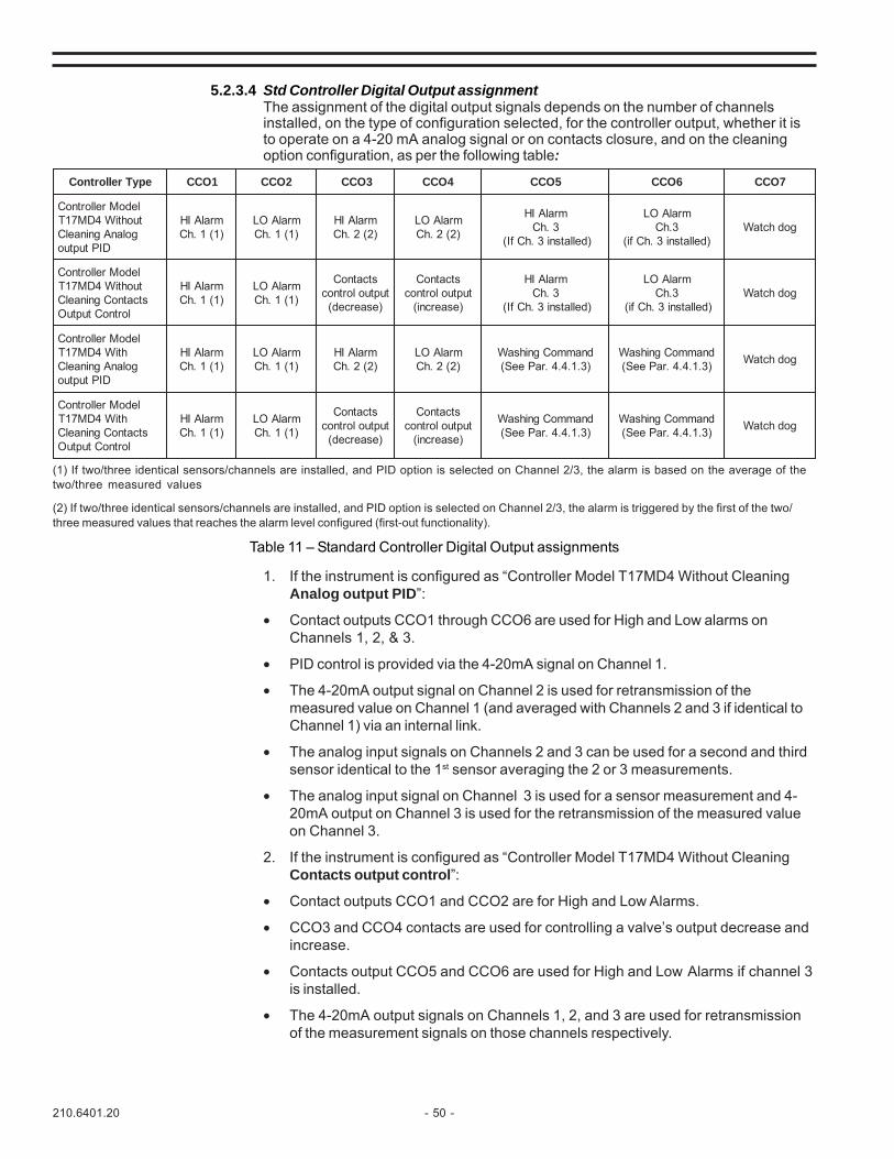
210.6401.20 - 50 -
5.2.3.4 Std Controller Digital Output assignmentThe assignment of the digital output signals depends on the number of channelsinstalled, on the type of configuration selected, for the controller output, whether it isto operate on a 4-20 mA analog signal or on contacts closure, and on the cleaningoption configuration, as per the following table:
(1) If two/three identical sensors/channels are installed, and PID option is selected on Channel 2/3, the alarm is based on the average of thetwo/three measured values
(2) If two/three identical sensors/channels are installed, and PID option is selected on Channel 2/3, the alarm is triggered by the first of the two/three measured values that reaches the alarm level configured (first-out functionality).
Table 11 – Standard Controller Digital Output assignments
epyTrellortnoC 1OCC 2OCC 3OCC 4OCC 5OCC 6OCC 7OCC
ledoMrellortnoCtuohtiW4DM71T
golanAgninaelCDIPtuptuo
mralAIH)1(1.hC
mralAOL)1(1.hC
mralAIH)2(2.hC
mralAOL)2(2.hC
mralAIH3.hC
)dellatsni3.hCfI(
mralAOL3.hC
)dellatsni3.hCfi(godhctaW
ledoMrellortnoCtuohtiW4DM71TstcatnoCgninaelC
lortnoCtuptuO
mralAIH)1(1.hC
mralAOL)1(1.hC
stcatnoCtuptuolortnoc
)esaerced(
stcatnoCtuptuolortnoc
)esaercni(
mralAIH3.hC
)dellatsni3.hCfI(
mralAOL3.hC
)dellatsni3.hCfi(godhctaW
ledoMrellortnoChtiW4DM71T
golanAgninaelCDIPtuptuo
mralAIH)1(1.hC
mralAOL)1(1.hC
mralAIH)2(2.hC
mralAOL)2(2.hC
dnammoCgnihsaW)3.1.4.4.raPeeS(
dnammoCgnihsaW)3.1.4.4.raPeeS( godhctaW
ledoMrellortnoChtiW4DM71T
stcatnoCgninaelClortnoCtuptuO
mralAIH)1(1.hC
mralAOL)1(1.hC
stcatnoCtuptuolortnoc
)esaerced(
stcatnoCtuptuolortnoc
)esaercni(
dnammoCgnihsaW)3.1.4.4.raPeeS(
dnammoCgnihsaW)3.1.4.4.raPeeS( godhctaW
1. If the instrument is configured as “Controller Model T17MD4 Without CleaningAnalog output PID”:
• Contact outputs CCO1 through CCO6 are used for High and Low alarms onChannels 1, 2, & 3.
• PID control is provided via the 4-20mA signal on Channel 1.
• The 4-20mA output signal on Channel 2 is used for retransmission of themeasured value on Channel 1 (and averaged with Channels 2 and 3 if identical toChannel 1) via an internal link.
• The analog input signals on Channels 2 and 3 can be used for a second and thirdsensor identical to the 1st sensor averaging the 2 or 3 measurements.
• The analog input signal on Channel 3 is used for a sensor measurement and 4-20mA output on Channel 3 is used for the retransmission of the measured valueon Channel 3.
2. If the instrument is configured as “Controller Model T17MD4 Without CleaningContacts output control”:
• Contact outputs CCO1 and CCO2 are for High and Low Alarms.
• CCO3 and CCO4 contacts are used for controlling a valve’s output decrease andincrease.
• Contacts output CCO5 and CCO6 are used for High and Low Alarms if channel 3is installed.
• The 4-20mA output signals on Channels 1, 2, and 3 are used for retransmissionof the measurement signals on those channels respectively.
- 51 - 210.6401.20
3. If the instrument is configured as “Controller Model T17MD4 With CleaningAnalog output PID”:
• Contact outputs CCO1 through CCO4 are used for High and Low alarms onChannels 1 and 2.
• The contact outputs CCO5 and CCO6 are used to control the wash and rinselines.
• PID control is provided to via the 4-20mA signal on Channel 1.
• The 4-20mA output signal on Channel 2 is used for retransmission of themeasured value on Channel 1 or the averaged measurements of Channels 1, 2and Channel 3 if installed via an internal link.
• The input signals on Channels 2 and 3 can be used for a second and third sensoridentical to the first sensor averaging the 2 or 3 measurements.
• The input signal on Channel 3 is used for a sensor measurement and 4-20mAoutput on Channel 3 is used for the retransmission of the measured value onChannel 3.
4. If the instrument is configured as “Controller Model T17MD4 With CleaningContacts Output Control”:
• Contact outputs CCO1 and CCO2 are used for High and Low Alarms.
• CCO3 and CCO4 are used for Contacts Control decrease and increase.
• The contact outputs CCO5 and CCO6 are used to control the wash and rinselines.
• The 4-20mA output signals on Channels 1 and 2 are used for retransmission ofthe measured value on Channel 1 and 2.
• The analog input signal on Channel 2 is used for the measured value.The analog input signal on Channel 3 is used for a sensor measurement and4-20mA output on Channel 3 is used for the retransmission of the measured valueon Channel 3.

210.6401.20 - 52 -
5.2.4 Averaging ControllerThe Averaging Controller is dedicated to processes that need high reliability of the analysis values in thelarge tanks and basins. MicroChem®2 supports three identical sensors and the calculated average valueis used in the PID algorithm as process variable. The difference between the average value (ProcessVariable, PV), and a Setpoint (SP) value is used to calculate an Output (OUT) signal that is applied to afinal control element to restore process analysis to the setpoint value. The output is calculated with thePID algorithm, which has Proportional, Integral and Derivative terms. The effect these terms have on theoutput calculation is determined by the PID configuration selections.
When the channel has been selected, selecting “YES” in the “Average” parameter appearing in theconfiguration menu activates the average value control strategy.
5.2.4.1 Averaging Controller DisplayThe MicroChem®2 supports two different displays. The main one shows the values used in thePID algorithm: the average value, the average value of the temperature, the setpoint and theoutput. The three secondary displays show the measurement and the temperature of each of thethree probes. To toggle from one display to another, press the END key.
Main display:• average value used in the PID algorithm• average value of temperature• setpoint• output• A/M (A = Automatic, M = Manual).Display fields are illustrated below:
Secondary display:• measurement of each single probe• temperature• channel number on display
5.2.4.2 Averaging Controller Digital Input assignmentThe Digital Input functionality is identical for all types of instruments selected, as perfollowing table:
Table 12 – Averaging Controller Digital Inputs Assignment
1 . 5 2 O 2 1 5 . 5 ° C
1 . 5 0 S P 1 6 O U T % A
Average value of O2
Setpoint
Average Temperature
Output (%) andAutomatic/Manual (A/M)
1 . 5 2 O 2 1 5 . 5 ° C
C H N 1
Instantaneous Measurement
Channel being displayed
Temperature
NOITCELES"RO"nilCC 1lCC 2lCC
="RO"nilCC ON 1lennahCfoeulavderusaemsezeerF 2lennahCfoeulavderusaemsezeerF)nezorfebtonnacenola3lennahC(
="RO"ni1CC SEY dellatsnislennahCllafoeulavderusaemsezeerF gnittestuptuo1DIP0otsecroF
="RO"niICC FFO delbasiD delbasiD

- 53 - 210.6401.20
5.2.4.3 Averaging Controller Analog Output assignmentThe assignment of the analog output signals depends on the number of channels installedand on the type of configuration selected for the controller output, whether it is to operateon a 4-20 mA analog signal or on contacts closure, as per the following table:
(1) If the PID option is selected on Channel 2, the output becomes the average of the two/three measured values
Table 13 – Averaging Controller Analog Output Assignments.
5.2.4.4 Averaging Controller Digital Output assignmentThe assignment of the digital output signals depends on the number of channels installed,on the type of configuration selected, for the controller output, whether it is to operate ona 4-20 mA analog signal or on contacts closure, and on the cleaning option configuration,as per the following table:
Table 14 – Averaging Controller Digital Output assignments
(1) If two/three identical sensors/channels are installed, and PID option is selected on Channel 2/3, the alarm is based on the average of thetwo/three measured values
(2) If two/three identical sensors/channels are installed, and PID option is selected on Channel 2/3, the alarm is triggered by the first of thetwo/three measured values that reaches the alarm level configured (first-out functionality).
epyTrellortnoC 1OCC 2OCC 3OCC 4OCC 5OCC 6OCC 7OCC
ledoMrellortnoCtuohtiW4DM71T
golanAgninaelCDIPtuptuo
mralAIH)1(1.hC
mralAOL)1(1.hC
mralAIH)2(2.hC
mralAOL)2(2.hC
mralAIH3.hC
)dellatsni3.hCfi(
mralAOL3.hC
)dellatsni3.hCfi(
hctaWgod
ledoMrellortnoCtuohtiW4DM71TstcatnoCgninaelC
DIPtuptuo
mralAIH)1(1.hC
mralAOL)1(1.hC
tcatnoCtuolortnoc)esaerced(
tcatnoCtuolortnoc)esaercni(
mralAIH3.hC
)dellatsni3.hCfi(
mralAOL3.hC
)dellatsni3.hCfi(
hctaWgod
ledoMrellortnoChtiW4DM71T
golanAgninaelCDIPtuptuo
mralAIH)1(1.hC
mralAOL)1(1.hC
mralAIH)2(2.hC
mralAOL)2(2.hC
gnihsaWdnammoc
)3.1.4.4.raPeeS(
dnammocgnihsaW)3.1.4.4.raPeeS(
hctaWgod
ledoMrellortnoChtiW4DM71T
stcatnoCgninaelCDIPtuptuo
mralAIH)1(1.hC
mralAOL)1(1.hC
tcatnoCtuolortnoc)esaerced(
tcatnoCtuolortnoc)esaercni(
gnihsaWdnammoc
3.1.4.4.raPeeS(
dnammocgnihsaW)3.1.4.4.raPeeS(
hctaWgod
rellortnoCfoepyT noitpotuptuO 1lennahCAm02-4 2lennahCAm02-4 3lennahCAm02-4
doMrellortnoC2htiW4DM71T
dellatsnislennahC
tuptuogolanA tuptuolortnoCDIPeulavderusaeM
fonoissimsnarter)1(sisylana1lennahC
----
tupptuostcatnoCeulavderusaeM
fonoissimsnartersisylana1lennahC
eulavderusaeMfonoissimsnarter
)1(sisylana2lennahC
doMrellortnoC3htiW4DM71T
dellatsnislennahC
tuptuogolanA tuptuolortnoCDIPeulavderusaeM
fonoissimsnarter)1(sisylana1lennahC eulavderusaeM
fonoissimsnartersisylana3lennahC
tuptuostcatnoCeulavderusaeM
fonoissimsnartersisylana1lennahC
eulavderusaeMfonoissimsnarter
)1(sisylana2lennahC
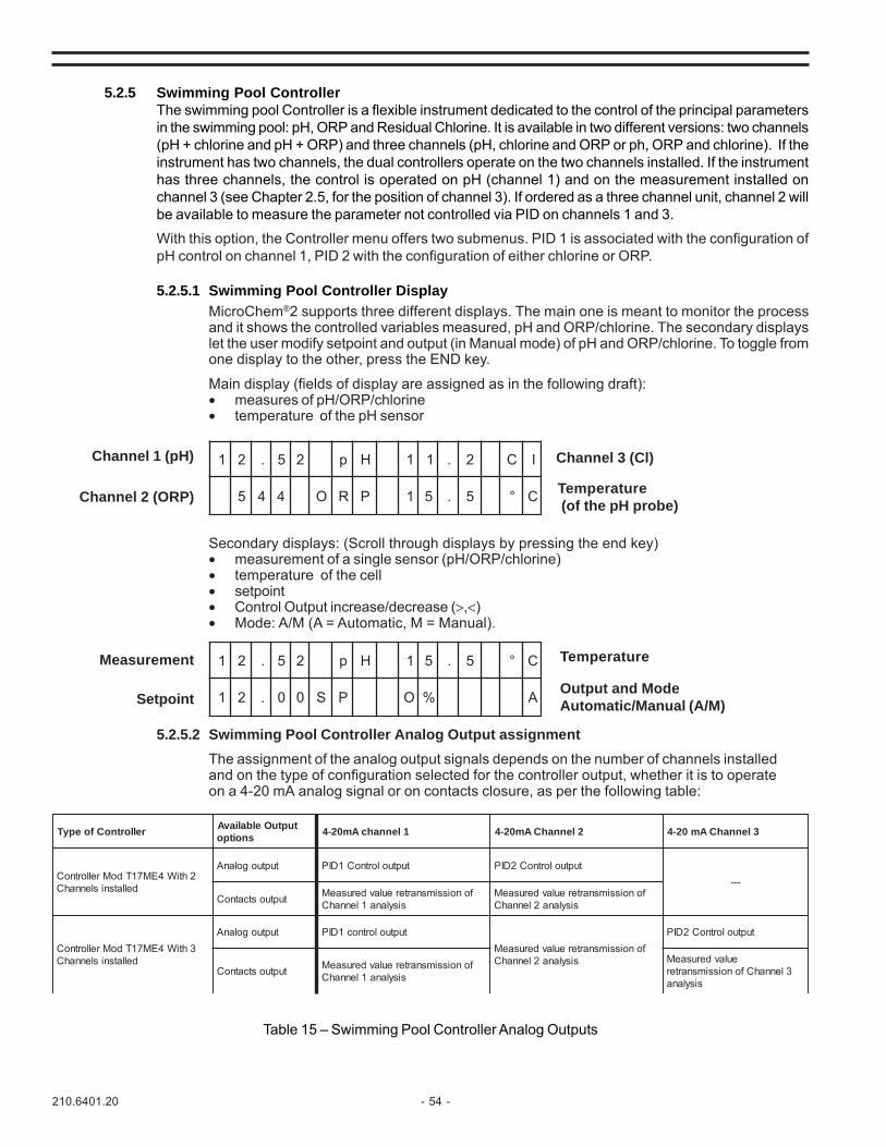
210.6401.20 - 54 -
5.2.5 Swimming Pool ControllerThe swimming pool Controller is a flexible instrument dedicated to the control of the principal parametersin the swimming pool: pH, ORP and Residual Chlorine. It is available in two different versions: two channels(pH + chlorine and pH + ORP) and three channels (pH, chlorine and ORP or ph, ORP and chlorine). If theinstrument has two channels, the dual controllers operate on the two channels installed. If the instrumenthas three channels, the control is operated on pH (channel 1) and on the measurement installed onchannel 3 (see Chapter 2.5, for the position of channel 3). If ordered as a three channel unit, channel 2 willbe available to measure the parameter not controlled via PID on channels 1 and 3.
With this option, the Controller menu offers two submenus. PID 1 is associated with the configuration ofpH control on channel 1, PID 2 with the configuration of either chlorine or ORP.
5.2.5.1 Swimming Pool Controller DisplayMicroChem®2 supports three different displays. The main one is meant to monitor the processand it shows the controlled variables measured, pH and ORP/chlorine. The secondary displayslet the user modify setpoint and output (in Manual mode) of pH and ORP/chlorine. To toggle fromone display to the other, press the END key.
Main display (fields of display are assigned as in the following draft):• measures of pH/ORP/chlorine• temperature of the pH sensor
Secondary displays: (Scroll through displays by pressing the end key)• measurement of a single sensor (pH/ORP/chlorine)• temperature of the cell• setpoint• Control Output increase/decrease (>,<)• Mode: A/M (A = Automatic, M = Manual).
5.2.5.2 Swimming Pool Controller Analog Output assignmentThe assignment of the analog output signals depends on the number of channels installedand on the type of configuration selected for the controller output, whether it is to operateon a 4-20 mA analog signal or on contacts closure, as per the following table:
Table 15 – Swimming Pool Controller Analog Outputs
1 2 . 5 2 p H 1 1 . 2 C I
5 4 4 O R P 1 5 . 5 ° C
Channel 1 (pH)
Channel 2 (ORP)
Channel 3 (Cl)
Temperature (of the pH probe)
1 2 . 5 2 p H 1 5 . 5 ° C
1 2 . 0 0 S P O % A
Measurement
Setpoint
Temperature
Output and ModeAutomatic/Manual (A/M)
rellortnoCfoepyT tuptuOelbaliavAsnoitpo 1lennahcAm02-4 2lennahCAm02-4 3lennahCAm02-4
2htiW4EM71TdoMrellortnoCdellatsnislennahC
tuptuogolanA tuptuolortnoC1DIP tuptuolortnoC2DIP---
tuptuostcatnoC fonoissimsnartereulavderusaeMsisylana1lennahC
fonoissimsnartereulavderusaeMsisylana2lennahC
3htiW4EM71TdoMrellortnoCdellatsnislennahC
tuptuogolanA tuptuolortnoc1DIPfonoissimsnartereulavderusaeM
sisylana2lennahC
tuptuolortnoC2DIP
tuptuostcatnoC fonoissimsnartereulavderusaeMsisylana1lennahC
eulavderusaeM3lennahCfonoissimsnarter
sisylana

- 55 - 210.6401.20
If the 4-20 mA output is used to control a pump, then the 4-20mA output sends a PID controlsignal on the 4-20 mA line. The 4-20mA output is not available for transmission of the actualmeasurement value. However, if the control is done by activating the CC03, 04, 05, 06 contactclosures (see 5.2.2.5) then the 4-20mA output is available and can transmit the measurementsignal.
5.2.5.3 Swimming Pool Controller Digital Input assignmentThe Digital Input functionality is identical for all types of instruments selected, as perthe following table:
Table 16 - Digital Input Functionality for Controller
NOTE 1: Freezing the channels is typically used when performing maintenance.NOTE 2: As a safety precaution, as a swimming pool controller, the measurement is still made and displayed.
5.2.5.4 Swimming Pool Controller Digital Output assignmentThe assignment of the digital output signals depends on the number of channels installed,on the type of configuration selected for the controller output, and whether it is to operateon a 4-20 mA analog signal or on contacts closure, as per the following table:
Table 17 – Swimming Pool Controller Digital Output assignments
epyTrellortnoC 1OCC 2OCC 3OCC 4OCC 5OCC 6OCC 7OCC
ledoMrellortnoC2htiW4EM71TgolanAsrosneS2&1DIPtuptuo
mralAIH1.hC
mralAOL1.hC
mralAIH2.hC
mralAOL)2(2.hC --- --- hctaW
god
ledoMrellortnoC2htiW4EM71T
tcatnoCsrosneS2ro1tuptuo
mralAIHtuo-tsriF
2/1.hC
mralAOLtuo-tsriF
2/1.hC
1tcatnoCtuolortnoc)esaerced(
1tcatnoCtuolortnoc)esaercni(
2tcatnoCtuolortnoc)esaerced(
2tcatnoCtuolortnoc)esaercni(
hctaWgod
ledoMrellortnoC3htiW4EM71T
golanAsrosneS2&1DIPtuptuo
mralAIH1.hC
mralAOL1.hC
mralAIH2.hC
mralAOL2.hC
mralAIH3.hC
mralAOL3.hC
hctaWgod
ledoMrellortnoC3htiW4EM71T
tcatnoCsrosneS2ro1tuptuo
mralAIHtuo-tsriF3/2/1.hC
mralAOLtuo-tsriF3/2/1.hC
1tcatnoCtuolortnoc)esaerced(
1tcatnoCtuolortnoc)esaercni(
2tcatnoCtuolortnoc)esaerced(
2tcatnoCtuolortnoc)esaercni(
hctaWgod
NOITCELES"RO"nilCC 1lCC 2lCC
="RO"nilCC ON )1(1lennahCfoeulavderusaemsezeerF )1(2lennahCfoeulavderusaemsezeerF)nezorfebtonnacenola3lennahC(
="RO"nilCC SEY )1(dellatsnislennahCllafoeulavderusaemsezeerF )2(slagnistuptuo2DIP&1DIP0otsecroF
="RO"niICC FFO delbasiD delbasiD
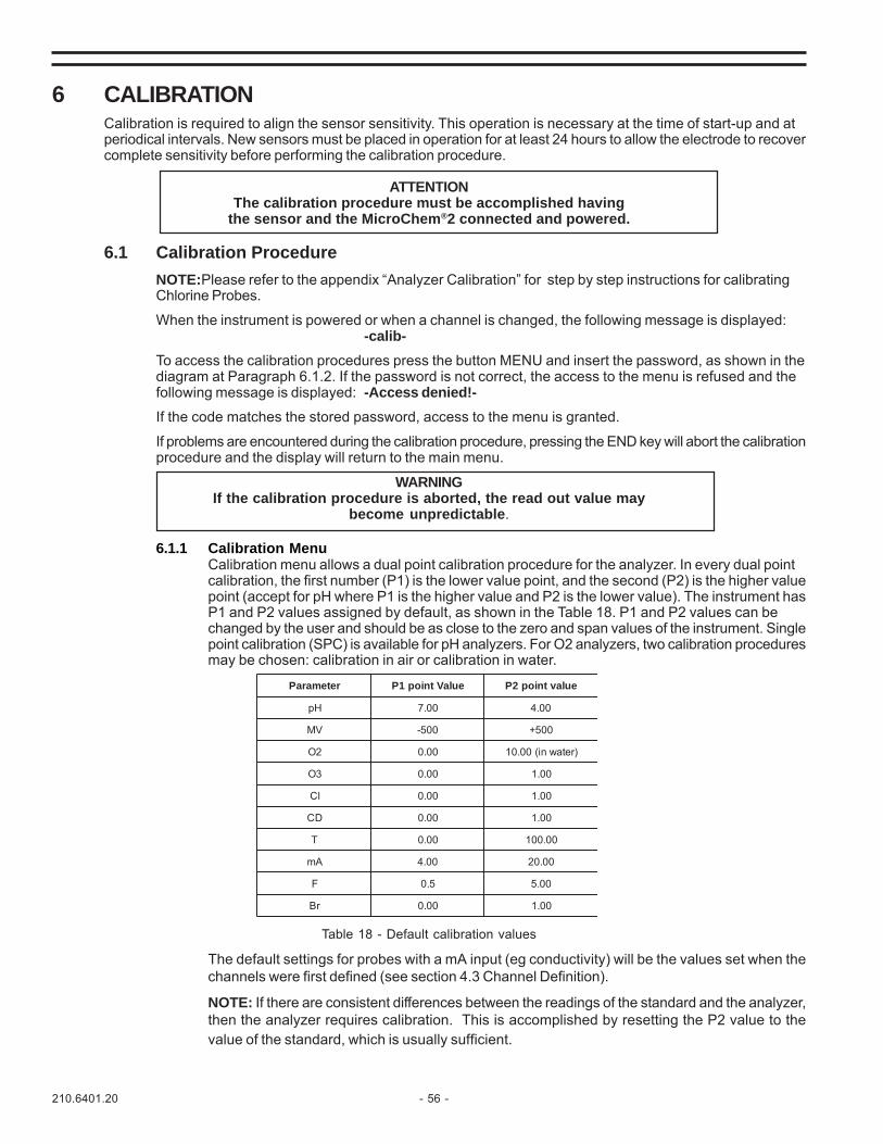
210.6401.20 - 56 -
6 CALIBRATIONCalibration is required to align the sensor sensitivity. This operation is necessary at the time of start-up and atperiodical intervals. New sensors must be placed in operation for at least 24 hours to allow the electrode to recovercomplete sensitivity before performing the calibration procedure.
ATTENTIONThe calibration procedure must be accomplished having
the sensor and the MicroChem®2 connected and powered.
6.1 Calibration ProcedureNOTE:Please refer to the appendix “Analyzer Calibration” for step by step instructions for calibratingChlorine Probes.
When the instrument is powered or when a channel is changed, the following message is displayed:-calib-
To access the calibration procedures press the button MENU and insert the password, as shown in thediagram at Paragraph 6.1.2. If the password is not correct, the access to the menu is refused and thefollowing message is displayed: -Access denied!-If the code matches the stored password, access to the menu is granted.
If problems are encountered during the calibration procedure, pressing the END key will abort the calibrationprocedure and the display will return to the main menu.
WARNINGIf the calibration procedure is aborted, the read out value may
become unpredictable.
6.1.1 Calibration MenuCalibration menu allows a dual point calibration procedure for the analyzer. In every dual pointcalibration, the first number (P1) is the lower value point, and the second (P2) is the higher valuepoint (accept for pH where P1 is the higher value and P2 is the lower value). The instrument hasP1 and P2 values assigned by default, as shown in the Table 18. P1 and P2 values can bechanged by the user and should be as close to the zero and span values of the instrument. Singlepoint calibration (SPC) is available for pH analyzers. For O2 analyzers, two calibration proceduresmay be chosen: calibration in air or calibration in water.
retemaraP eulaVtniop1P eulavtniop2P
Hp 00.7 00.4
VM 005- 005+
2O 00.0 )retawni(00.01
3O 00.0 00.1
lC 00.0 00.1
DC 00.0 00.1
T 00.0 00.001
Am 00.4 00.02
F 5.0 00.5
rB 00.0 00.1
Table 18 - Default calibration values
The default settings for probes with a mA input (eg conductivity) will be the values set when thechannels were first defined (see section 4.3 Channel Definition).
NOTE: If there are consistent differences between the readings of the standard and the analyzer,then the analyzer requires calibration. This is accomplished by resetting the P2 value to thevalue of the standard, which is usually sufficient.

- 57 - 210.6401.20
6.1.2 Calibration Menu Flow Chart
(Please refer to the menu trees in the appendixes for an overview of how to navigate through the software.)
6.1.3 pH Sensor Calibration
The calibration procedure is necessary to stabilize the sensor sensitivity.
The double point calibration gives the maximum accuracy because it sets both the slope and the offset ofthe curve giving displayed pH value as a function of the mV from the probe (sensitivity).
The first point can be calibrated using 7 pH buffer solution (0mV) and the second point can be calibratedusing 4pH buffer solution. Both these solutions are available from Severn Trent Services, complete withthe table for the variation of the pH value as a function of the variations of temperature; however theoperator can use other buffer solutions, if they have distant enough pH values and have the same accuracyas Severn Trent Services’.
6.1.3.1 Double point calibrationThe calibration procedure involves a series of operations on the pH probe and the transmitter. Thefollowing description explains step by step the calibration procedure, with the buffer solutionsupplied by Severn Trent Services.
To operate the calibration the following material is necessary:
- two plastic or glass beakers
- standard buffer solution, pH 7 and pH 4 or other, (see paragraph 6.1.3)
- demineralized water
- a thermometer

210.6401.20 - 58 -
Severn Trent Services optionally supplies a calibration kit (P/N 1T141B008U02), including : 50 capsules of standard buffer solution pH 7 50 capsules of standard buffer solution pH 4 50 capsules of standard buffer solution pH 9
Each of these capsules is suitable to prepare 100 ml of solution.
If the sensor is new and has been stored dry, leave it immersed in water for 24 hours to allow thehydration of the glass sensitive membrane and of the porous diaphragm. If it has been stored wethalf an hour is enough for the stabilization.
Prepare the buffer solution in volumetric flasks: for the preparation of each buffer solution dissolvethe capsule in the flask. Add 80 ml of distilled water in the flask and stir carefully until thecapsule is completely dissolved. Then add water until the correct volume is reached. For twopoint calibrations, use pH7 buffer or pH10 buffer depending upon the pH setpoint. Put twostandard buffer solutions in two beakers in a sufficient amount to cover the sensor. Wash theprobe with demineralized water, dry it and dip it in the standard pH 7 buffer solution. Stir theprobe softly but continuously: in this way a lower stabilization time will be required.
1. Press the MENU key to enter the Instrument Calibration submenu and enter theCALIBRATION menu and then the channel of the pH probe.The display will show:
X X . X X p H 2 3 . 5 ° C
P 1 : Y Y . Y
P1 indicates the first point of calibration at HIGHER pH (pH 7). XX.XX shows when stability ofmeasurement has been reached. YY.Y is a value set at the last calibration and can be freelymodified according to the chosen buffer solution.
2. Press ENTER and insert the correct value. Wait 3 minutes after the measurement inXX.XX has stabilized (XX.XX is stable),
3. Press ENTER to save the value (press END if you do not want to save the value).If the following message appears:
-Bad Input!-It means the buffer solution is bad since the mV values generated are too close.
4. Pass on to the second point (P2) of the calibration by pressing the MENU key. Take thesensor out of the 7 standard buffer solution, rinse it thoroughly with demineralized water,dry it and immerse it in the 4 pH std buffer solution furnished by Severn Trent Services orin another buffer solution of same value. Stir the probe softly but continuously: in thisway a lower stabilization time will be required.
5. Wait until the value in XX.XX is stabilized (XX.XX is stable) and correct the pH value inYY.Y.
6. Confirm by pressing the ENTER key. Previously stored values are overwritten in non-volatilememory.
7. To start the measurement, press the END key and the display will show the actualmeasured value.
6.1.3.2 Single point calibration (S.P.C.)The single point calibration may be performed ONLY IF A DOUBLE POINT CALIBRATION HASALREADY BEEN PERFORMED. The single point calibration is a fast procedure to correct thesensitivity of an instrument while leaving it working in the field; however it’s less accurate than thedouble point calibration and must be performed as near as possible to the pH value of the processliquid. The single point calibration corrects the intercept pH curve by offsetting the displayedvalue by the value entered, but doesn’t vary its slope. For example: Display reads pH 7.7. ActualpH of sample (or calibration standard) being measured is 7.9. Enter 0.2 to shift the interceptcurve and change the display to pH 7.9.

- 59 - 210.6401.20
To perform the single point calibration:1. Measure the pH value of the process fluid near the location of the sensor (if it is constant
during the time interval needed for the calibration).2. Insert the pH value in YY.YY.
Entering the Calibration menu the following display will appear:
When a double point calibration is performed the S.P.C. value is forced to 0.00.
X X . X X p H 2 3 . 5 ° C
p H S P C : Y Y . Y Y
Figure 15 - pH Calibration curves examples
NOTE: Single point calibration corrects the sensitivity in the zone where the correctionis made. It is therefore necessary to operate single point calibration as near aspossible to the process fluid pH value.IMPORTANT: THESE CURVES ARE ONLY A THEORETICAL REPRESENTATION, NOTBASED ON EXPERIMENTAL VALUES.
6.1.4 ORP Sensor CalibrationThe calibration procedure is necessary to stabilize the sensor sensitivity. The double point calibrationgives the maximum accuracy because it sets both the slope and the offset of the curve giving adisplayed ORP value as a function of the mV from the probe (sensitivity).Severn Trent Services does not supply ORP buffer solution, they are however readily available on themarket.The calibration of the ORP analyzer is not usually required, however the two point calibration procedureis available in the transmitter software.NOTE: The calibration procedures are different for “oxidation potential with negative value”and “oxidation potential with positive value”. Both are described in the following pages.

210.6401.20 - 60 -
The calibration procedures involve both the electronic transmitter and the sensor. The followingdescription indicates step by step the double point calibration procedure:To operate the calibration, the following material is necessary:
- two plastic or glass beakers- standard ORP solutions.
Pour the two standard ORP solutions in two beakers in a sufficient amount to cover the sensor. Wash theprobe with demineralized water, dry it and dip it in the first buffer solution. Stir the probe softly butcontinuously: in this way a shorter stabilization time will be required.6.1.4.1 “OXIDATION potential with NEGATIVE values” arrangement
P1 will be the value of the oxidant standard solution, and P2 the value of the reductant standardsolution. In case both the standard solutions have the same sign, P1 will be the standard solutionwith the lower value.
1. Press the MENU key to enter the Instrument Calibration submenu and enter theCALIBRATION menu and then the channel of the ORP probe.The following display will appear:
X X . X X R X 2 3 . 5 ° C
P 1 : Y Y . Y
P1 indicates the first point of calibration. XX.XX shows when the stability of measurement hasbeen reached. YY.Y is a value set at the last calibration and can be freely modified accordingto the chosen buffer solution.
2. Press ENTER and insert the correct value. Wait 3 minutes after the measurement inXX.XX has stabilized (XX.XX is stable)
3. Press ENTER to save the value (press END if you don’t want to save the value).4. Pass on to the second point (P2, higher value) of calibration pressing the MENU button.
Take the sensor out of the first standard solution rinse it thoroughly with demineralizedwater, dry it and immerse it in the second standard solution. Stir the probe softly butcontinuously: in this way a shorter stabilization time would be required.Wait until the measurement is stabilized (no more variations of XXXX shown on thedisplay).If needed, correct the ORP value pressing the ENTER key and inserting the correct value,according to the second buffer solution ORP value. If you want to save these values push theENTER key. If you don’t want to save above mentioned calibration parameters press END. Ifthe ENTER key is pressed new calibration data is overwritten to previously stored values innon-volatile memory.To start the measurement, press the END key and the display will show the measured value.
NOTE: The calibration procedure can be performed also at two values, which are outsidefrom the measuring range selected, depending on the buffer solutions, which are availablefor the calibration.
6.1.4.2 “OXIDATION potential with POSITIVE values” arrangementCalibration is similar to the previous one but P1 is the value of the reductant standard solution,and P2 the value of the oxidant standard solution. In case both the standard solutions have thesame sign, P1 will be the standard solution with the lower value.
6.1.5 Chlorine / Chlorine Dioxide / Ozone/ Bromine - KC4000 Cell or CL4000 ProbesThe calibration procedure is necessary to stabilize the sensor sensitivity. The calibration procedure setsboth the slope and the offset of the curve giving the chlorine/chlorine dioxide/ozone/bromine concentrationas a function of the μA from the cell/probe (sensitivity).Severn Trent Services analyzers allow an easy two point calibration and the two points can be freelychosen, provided they are distant enough and inside the selected measuring range. In this way theinstrument is given all the parameters it needs to fix the calibration curve. The calibration proceduresinvolve both the transmitter and the sensor.

- 61 - 210.6401.20
The following description indicates step by step the calibration procedure:
1. If the cell is new or recently cleaned, leave it working for 24 hours so that the electrodes cangain the correct sensitivity.P1 — Low Calibration
NOTE: P1 calibration is only necessary for the initial calibration to set the zero point.When performing a recalibration it is only necessary to RESET the P2.
2. Enter the Instrument Calibration submenu and using the menu key, change the channel forcalibration and press ENTER until the following display appears:
Notes1 – The name of the sensor chosen in the channel definition will appear where CL is displayed.2 – The temperature will appear if a temperature sensor is installed
P1 (Y.YYY) indicates the first point in calibration (the lower point). XX.XXXX is the measured parameterconcentration reading. This reading is based upon calibration parameters previously stored. XX.XXXserves as an indication of the stability of the measure. 0.000 is a default ppm value and can be freelychanged. Y.YYY is a value set at the last calibration and can be freely modified.
3. To zero the instrument, place a dechlorinating filter (P/N 1D617A004U01 or P/N 1D617A004U02- includes a 3/8” to 1/4” adapter, see Section 10.2) in the sample line. Open the sample flowto the cell. Continue to run dechlorinated water to the cell until the measurement stabilizes.Perform a laboratory analysis on the sample being measured to determine your P1 value.Correct the P1 value if needed. Confirm with the entry key.If the message – Bad Input!— appears. It means the P1 and P2 calibration points are too close. Seethe trouble shooting section of the CL4000 or KC4000 manual. The message can be overwritten bypressing the END key.
If ENTER is pressed new calibration data (i.e. uA corresponding to the displayed ppm value) isoverwritten to previously stored values in the non-volatile memory.
4. Press ENTER and insert the correct low calibration point value.5. Press ENTER again to confirm.
6. Press the MENU button to pass on the second (P2) calibration
7. Allow a sample flow to the cell (with a concentration as near as possible to the chosen full-scale) and let it stabilize (stabilization time depends on the plant configuration).
8. Take a sample from the drain tube. Analyze the solution for the measured parameter.P2 — High Calibration – P2 indicates the second point in the calibration (the higher point)
XX.XXXX is the measured parameter concentration reading. This reading is based upon calibrationparameters previously stored. XX>XXX serves as an indication of the stability of the measure. 0.000 is adefault ppm value and can be freely changed. Y.YYY is a value set at the last calibration and can be freelymodified.
9. Press ENTER and insert the correct high calibration point value.10. Press ENTER again to confirm.REMARK: Multiply the DPD analysis by 1.9 if the sample being measured is a chlorine dioxide solution.
WARNINGIt is advisable to repeat the calibration after 24 hours and
again after 2 to 3 days
X X . X X X C L1 2 3 . 5 ° C2
P 1 : Y Y . Y
X X . X X X C L1 2 3 . 5 ° C2
P 2 : Y Y . Y

210.6401.20 - 62 -
6.1.6 Dissolved oxygen calibrationThe calibration procedure is necessary to stabilize the sensor sensitivity. The calibration procedure setsboth the slope and the offset of the curve giving the dissolved oxygen concentration as a function of the μAfrom the cell (sensitivity). This analyzer allows an easy two point calibration and the two points can befreely chosen; usually the calibration is performed at 0 ppm O2 and either at the saturation point of waterin the conditions (altitude, temperature) of the process or at the sample dissolved oxygen concentrationmeasured with a D.O. meter. In this way the instrument has all the parameters to fix the calibration curve.
The calibration procedures involve both the transmitter and the sensor. The following description indicatesstep by step the calibration procedure:
WARNINGThe altitude parameter must be set to result in a proper calibration
Prepare the sensor as described in Instruction Bulletin DO4000 (223.6005), and then leave it workingfor approx. 2 hours so that the system can gain the correct sensitivity.
WARNINGWhen the sensor is disconnected from the transmitter and then reconnected, it polarizes and generates a signal that is much higher than a normal signal.
The transmitter may in this case indicate a fixed value higher than the fullscale value. The reading becomes normal when the input signal returns
to normal limits.
WARNINGIt is advisable to repeat the calibration after 24 hours and after 2/3 days.
6.1.6.1 Calibration in water1.Press the MENU key to enter the Instrument Calibration submenu and enter the
CALIBRATION menu and then the channel of the DO probe. Select calibration in water.The following display will appear:
X X . X X D O 2 3 ° C
P 1 : Y Y . Y
P1 indicates the first point in calibration, XX.XX is a dissolved oxygen concentration reading.This reading is based upon calibration parameters previously stored. XX.XX serves as an indicationof the stability of the measurement.0.00 is a default ppm value and can be freely changed. YY.Y is a value set at the lastcalibration and can be freely modified.
2.Fill a beaker with 250 ml of distilled water and add about 10 g of sodium sulphite(Na2SO3). Let the salt dissolve and immerse the probe being careful not to damagethe membrane and the electrode. Let the measurement stabilize and confirm thezero ppm pushing the ENTER key.3.If you want to save the value press ENTER. If you don’t want to save the above mentioned
calibration parameters press END. So forth, previously stored parameters aren’t destroyed andthey remain valid for the computation (if the range setting has not been changed).If the following message appears: -Bad Input!-It means the zero solution is bad since the mV values generated are too close. This messagecan be overwritten by pressing the END key.
4.If -Bad Input!- appears a second calibration attempt should be made. The probe may needadditional time to stabilize. If the -Bad Input!- message continues, make up another P1solution and calibrate P1. IF -Bad Input!- continues, check the probe membrane, connections,channel definition, etc.
5.Pass on to the second point (P2) of calibration pressing the button MENU.a. Fill a vessel with distilled water and insufflate air for at least 10 minutes, keeping
the probe immersed (be careful not to damage membrane and electrode).

- 63 - 210.6401.20
b. Wait 10 minutes and, if XX.XX is stable, correct the value in YY.YY with the value intable 19.
c. To start the measurement, press the END key and the display will show the measuredvalue.
6.1.6.2 Calibration in airFrom the CALIBRATION menu, chose calibration IN AIR. Calibrate P1 (zero) as describedbefore. Pass on to the second point (P2) of calibration pressing the MENU button. Thefollowing display will appear:
Where YY.YY is the value of saturation of oxygen in air at the temperature measured by thethermistor and at the set altitude.Proceed in this way for the calibration IN AIR of P2: lift the DO sensor and suspend in air,keeping it over a vessel containing water (the sensor must not be in contact with the water).This operation simulates a condition of "air saturated with water". Avoid exposing the sensor todirect sunlight as the sunlight may increase the temperature to the point where the temperaturecompensation is inserted. Wait 5 minutes or until that the value in XX.XX is stable, then confirmthe value determined via software displayed in YY.YY pressing ENTER. To pass to the displaymode press the END key.
Y Y . Y Y F 2 3 . 5 ° C
X X : X X Y Y . Y Y

210.6401.20 - 64 -
C°T F°T ).M.L(leveLaeS
m021tf093
m042tf977
m563tf5811
m094tf1951
m016tf0891
m057tf5342
m058tf0672
m579tf6613
m0011tf753
0 0.23 06.41 04.41 01.41 09.31 07.31 05.31 02.31 09.21 07.21 05.21
1 8.33 02.41 00.41 08.31 06.31 03.31 01.31 09.21 06.21 04.21 02.21
2 6.53 09.31 07.31 04.31 02.31 00.31 09.21 06.21 03.21 01.21 08.11
3 4.73 05.31 03.31 01.31 09.21 07.21 04.21 02.21 00.21 08.11 05.11
4 2.93 02.31 09.21 07.21 05.21 03.21 01.21 09.11 07.11 04.11 02.11
5 0.14 08.21 06.21 04.21 02.21 00.21 08.11 06.11 04.11 01.11 09.01
6 8.24 05.21 03.21 01.21 09.11 07.11 05.11 03.11 01.11 09.01 07.01
7 6.44 02.21 00.21 08.11 06.11 04.11 02.11 00.11 08.01 06.01 04.01
8 4.64 09.11 07.11 05.11 03.11 01.11 09.01 07.01 05.01 03.01 01.01
9 2.84 06.11 04.11 02.11 01.11 09.01 07.01 05.01 03.01 01.01 09.9
01 0.05 03.11 01.11 09.01 08.01 06.01 04.01 02.01 00.01 09.9 07.9
11 8.15 01.11 08.01 06.01 05.01 03.01 01.01 09.9 07.9 06.9 04.9
21 6.35 08.01 06.01 04.01 03.01 01.01 09.9 07.9 05.9 04.9 02.9
31 4.55 06.01 03.01 02.01 00.01 08.9 07.9 05.9 04.9 02.9 01.9
41 2.75 04.01 01.01 00.01 08.9 07.9 05.9 03.9 02.9 00.9 09.8
51 0.95 02.01 09.9 08.9 06.9 05.9 03.9 01.9 00.9 08.8 07.8
61 8.06 00.01 07.9 06.9 04.9 03.9 01.9 09.8 07.8 06.8 05.8
71 6.26 07.9 05.9 04.9 02.9 01.9 09.8 07.8 06.8 04.8 04.8
81 4.46 05.9 04.9 02.9 01.9 09.8 08.8 06.8 05.8 03.8 02.8
91 2.66 04.9 02.9 00.9 09.8 07.8 06.8 04.8 03.8 01.8 00.8
02 0.86 02.9 00.9 08.8 07.8 05.8 04.8 02.8 01.8 09.7 08.7
12 8.96 00.9 08.8 06.8 05.8 03.8 02.8 00.8 09.7 07.7 06.7
22 6.17 08.8 07.8 05.8 04.8 02.8 01.8 09.7 08.7 06.7 05.7
32 4.37 07.8 05.8 03.8 02.8 00.8 09.7 07.7 06.7 04.7 03.7
42 2.57 05.8 03.8 01.8 00.8 08.7 07.7 05.7 04.7 02.7 01.7
52 0.77 04.8 02.8 00.8 08.7 07.7 06.7 04.7 03.7 01.7 00.7
62 8.87 02.8 00.8 08.7 07.7 05.7 04.7 02.7 01.7 09.6 08.6
72 6.08 01.8 09.7 07.7 06.7 04.7 03.7 01.7 00.7 08.6 07.6
82 4.28 09.7 07.7 06.7 04.7 03.7 02.7 01.7 09.6 08.6 07.6
92 2.48 08.7 06.7 05.7 03.7 02.7 01.7 00.7 08.6 07.6 06.6
03 0.68 06.7 04.7 01.7 01.7 00.7 09.6 08.6 06.6 05.6 04.6
NOTES:* This table refers to distilled water with no chlorides* The atmospheric pressure at sea level is considered at 760 mm/Hg* The air is considered water saturated* The error, using dry air, is negligible:
Example: at 25°C at sea level with relative humidity of 50%, the error is 0.15 ppm O2, and with dry air the error is 0.3 ppm O2.
Table 19

- 65 - 210.6401.20
6.1.7 Fluoride
The calibration procedure is necessary to maximize sensory accuracy. The calibration procedure setsboth the slope and the offset of the curve giving the fluoride concentration as a function of the mV from theprobe.
The first point can be calibrated with a 0.5 ppm Fluoride standard (P1) and the second point (P2) using a5.0 ppm Fluoride standard. Both these solutions are available from Severn Trent Services. The operatorcan use other concentration values.
If the sensor is new or has been stored dry please leave it immersed in water for 24 hours before calibrating.A second calibration is recommended 3-5 days after the initial calibration.
Prepare the two calibration solutions ensuring there is enough of each in separate bottles. Do notimmerse the probe in the standards bottles. Pour the standards into separate vessels to avoid contaminatingthe standards by the fluoride probe. For the immersion probe you will need to cover the bottom 3 inches(75mm) of the probe. For the panel mounted cell model at least 50 mls of each standard is required forcalibration. For panel mounted probes it is recommend that any standing sample in the cell be evacuatedprior to the low and high calibration by removing the sample plug momentarily to drain the cell.
1.Press the MENU key on the transmitter. Enter the password and then press Enter to get to theCalibration submenu. Enter this screen and use the Menu key to scroll to the channel of thefluoride probe. Use the Enter key to select this channel. The Menu key can be used to scroll toeither the measure P1 (low fluoride standard) or P2 (the high calibration standard). Enter the P1 screen.The display will show:
P1 indicates the first point of calibration at the LOWER fluoride concentration (0.5 ppm). XX.XX is thecurrent value. It is useful as it shows when measurement stability has been reached. YY.YY is thevalue set at the last calibration and can be freely modified.
2.For immersion probes place the probe in the P1 calibration standard ensuring that the bottom3 inches (75mm) of the probe are covered. For panel mounted cell models, remove thesample tube from the sample pot cap, and insert into the standard bottle (so the end of thetube is immersed).
3.Press the ENTER key on the transmitter and insert the correct value. Wait 10 minutes or untilthe reading has stabilized (XX.XX is stable), then confirm by pressing the ENTER key to savethe value or reject by pressing the End key
4.Proceed to the second point (P2) by pressing the MENU key. For immersion probes remove theprobe from the 0.5 ppm standard, rinse it with demineralized water, and put it in the 5.0 ppmfluoride standard ensuring that the bottom 3 inches (75mm) of the probe are covered. Wait 10minutes or until the measured reading (XX.XX) has stabilized and insert the correct standardvalue in YY.YY. Confirm by pressing Enter or reject by pressing the End key.
5.To start the measurement press the End key repeatedly until you are in the run mode, and putthe probe back into the sample stream (immersion probe) or fit the side sample top cap backin place (panel mounted cell model).
If at anytime during the calibration procedure the following message appears:
Bad InputIt means there was not enough difference in signal seen between standards. This message can beoverwritten by pressing the END key. However the standards should be replaced and the probe re-calibrated.
X X . X X F 2 3 . 5 ° C
P 1 : Y Y . Y Y

210.6401.20 - 66 -
6.1.8 Calibration of Sensors with a mA input (eg Conductivity)The calibration procedure is necessary to maximize sensor accuracy. The calibration procedure is verysimilar to the calibration procedure of any other of the sensors attached to the MicroChem2.
The calibration procedure sets both the slope and the offset of the curve giving the sensor concentration(in chosen units) as a function of the mA input from the sensor.
Two calibration solutions are required – a low (P1) and a high (P2). The actual calibration proceduredepends on the sensor used. Detailed below is a description of a typical calibration sequence for the4-20mA input conductivity probes supplied by Severn Trent Services.
Prepare the two calibration solutions (for conductivity see the EC4000 instruction bulletin for solutionsreadily available from Severn Trent Services). If the sensor is new or has been stored dry please leave itimmersed in water for 2 hours before calibrating. Another calibration is recommended 24 hours later.
1.Prepare the two calibration solutions and put enough of each in a beaker or bottle (itneeds to cover the bottom 50 mm (2 inches) of the probe).
2.Press the MENU key on the transmitter. Enter the password and then press Enter to get tothe Calibration submenu. Enter this screen and use the Menu key to scroll to the channelto be calibrated. Use the Enter key to select this channel. The Menu key can be used toscroll to either the measure P1 (low standard) or P2 (the high calibration standard). Enterthe P1 screen. The display will show:
1 Units will depend on those set by the customer – see section 4.3
P1 indicates the first point of calibration at the LOWER concentration. XX.XX is the current value. Itis useful as it shows when measurement stability has been reached. YY.YY is the value set at thelast calibration and can be freely modified.
3.Place the probe in the P1 calibration standard. Press the ENTER key on the transmitter andinsert the correct value. Wait 2 minutes or until the reading has stabilized (XX.XX is stable),then confirm by pressing the ENTER key to save the value or reject by pressing the END key.
4.Proceed to the second point (P2) by pressing the MENU key. Take the probe out of the lowstandard, rinse it with demineralized water, and put it in the high standard ensuring thebottom 50mm (2 inches) of the probe is covered. Wait 2 minutes or until the measuredreading (XX.XX) has stabilized and type in the correct standard value in YY.YY. Confirm bypressing Enter or reject by pressing End.
5.To start the measurement press the End key repeatedly until you are in run mode, and putthe probe back into the sample stream.
If at anytime during the calibration procedure the following message appears:
BAD INPUTIt means there was not enough difference in signal seen between standards. This message can beoverwritten by pressing the END key. However the standards should be replaced and the probe re-calibrated.
X X . X X U S1 2 3 . 5 ° C
P 1 : Y Y . Y Y

- 67 - 210.6401.20
7 START UPCAUTION
Disconnect Power Supply before opening the transmitter covers.
Before start up it is recommended that the following points are verified:• the power source jumper is set to the correct position (110 or 220 Vac)• power supply wiring meets all local codes and regulations• all electrical connections to MicroChem®2 are correct• the transmitter location fulfils requirements indicated in Sect. 3.3 of the present instruction manual.• the sensor installation allows easy lifting for cleaning, calibration and maintenance• sensor has been prepared and installed as per the sensor’s instruction manual• sensor cable is not run with other cables• 4-20 mA wiring is not run with other cables• digital input and relay output wiring is correct
7.1 Preliminary operationsCAUTION
The transmitter must be closed before being powered up.
7.1.1 Getting started - Refer to the Menu Trees and Step by Step Instructions in the Appendix.Perform the following steps:1. Turn on power supply;2. If the displayed measured value is not in agreement with the connected sensor(s) enter the
Channel Definition menu, and set, for each installed channel, the correct type of measurement.Refer to Sect. 4.3;
3. Output Settings - Set the output settings desired. See 4.4.2 for further information.4. Default alarm settings are 10% and 90% of measuring range. Enter the Alarms menu and set Low
Alarm and High Alarm level as required. Refer to Section 4.4.3;5. Verify that all Configuration parameters are set as required (See Section 4.4 to 4.4.1.3);6. If a Dissolved Oxygen Sensor (O2) is installed, set the installation altitude value, to allow
automatic calibration in air;7. Once the sensor(s) sensitivity is stabilized the calibration procedure(s) must be performed to
stabilize the transmitter together with the connected sensor(s); see Section 6 for calibration details.8. During the first 4 days of operation, it is suggested that the analyzer readings are verified daily,
and repeat calibration if necessary;9. Now the analyzer is in operation. It is important to follow the recommended maintenance
guidelines detailed in the instruction manuals for each sensor.
NOTE: Continuous sample flow to the measuring cell(s) and probe(s) are required. If the sample flowfluctuates or stops, recalibration will be necessary.
7.1.2 Configuration of Parameters1. If the Input/Output digital contacts are used, enter the Configuration menu and set the NO or NC
Status of the contact as desired;2. It is important to remember that any device connected to the digital output must be arranged in
order to operate in fail safe condition;3. If the Serial Communication option has been selected, enter the Configuration menu and set the
desired instrument address, baud rate and selected communication port;4. Select the desired engineering unit for the temperature indication;5. If it is desired to operate the controller with the average value of 2 or 3 identical sensors, select
PID in the Channel installation menu;6. If it is desired that the transmitter calculates the difference between two identical sensors input
values, set a value in the “Delta” parameter;7. If required, select a damping value for each channel input;8. Modify the “Password” in the Configuration menu, if it is desired to set a personalized access
code.

210.6401.20 - 68 -
7.2 Controller PID tuningThe PB, TR, and TD constants are preset to the default values shown in Table 8. If desired, using a trial anderror method as outlined below can optimize the control action settings.1. Set process to approximately normal conditions in MANUAL;2. Preset constants to some acceptable starting point for the process.
For example:PB = 75 to 125%TR = 30TD = 0
3. Switch Controller to AUTO mode;4. Decrease the PB setting to ½ the previous value. Then, alter the set point 2% by pressing one of the set
point push-buttons; blue buttons SP/6 or SP/7.5. Check that the process indication value does not oscillate;6. Continue to decrease the PB setting by a factor of 2, altering the set point between steps until a point is
reached where process cycling is just evident. Then increase the PB setting by a factor of 2;7. Introduce Automatic Reset slowly by decreasing TR until cycling starts;8. Increase TR to approximately 1.5 times the value obtained in step 7 above;When PID tuning constants have been selected, the controller is ready for on-line operation. Optional PIDtuning methods may be desired for slow response processes.

- 69 - 210.6401.20
8 MAINTENANCE
The MicroChem®2 housing can be externally cleaned with a cloth slightly wetted with alcohol and water, payingattention not to damage the keyboard.
CAUTIONDo not use acids, chemicals solvents and organic
substances for cleaning the housing of the MicroChem®2 cleaning.
8.1 Periodical operationsAll analyzer sensors need cleaning at periodical intervals depending on the type of sensor and processcharacteristics. For further details refer to the specific sensor Instruction Manual. The analyzer mayalso needs periodical sensitivity and calibration checks.
8.1.1 Automatic sensitivity check during dual point calibrationDuring dual point calibration, and if neither of the two points was bypassed, the MicroChem®2performs an automatic sensor sensitivity check. If the sensitivity is too low the display will showthe message Bad In. Refer to the instruction manual pertinent to each specific sensor for detailson how to fix the problem. If the message Fault appears the signal generated by the sensor isabnormally high. Refer to the instruction manual pertinent to each specific sensor for details onhow to fix the problem.
8.1.2 Sensor signal checkThe signal generated by the sensor and by the temperature compensation element can be readdirectly (in μA or mV and in ohms ) on the MicroChem®2 display by entering the Analog I/O,input signals submenu, under the Instrument Test submenu. This is a very easy way to determineif the sensor is working correctly or to just verify its signal for comparison to a lab analysis of themeasured value. See the pertinent instruction manual for the expected nominal signals for eachtype of sensor.

210.6401.20 - 70 -
9 ERROR MESSAGES & TROUBLESHOOTING
9.1 MessagesAt power up, the instrument shows the following sequence of messages:“MicroChem II”“S.Rel....”“Transmitter”
9.1.1 Operation messagesMessages displayed during operation.
“Loading default database”is shown when a reset has been performed. After some seconds the instrument goes to normal displaymode.
“-calib-”is shown when the instrument is powered and when a Channel has been changed. After a few secondsthe instrument goes to normal display mode.
“—wash—”flashes when the instrument is performing a cleaning sequence. Both the displayed measure and the 4-20 mA output signal are frozen at that last value.
“Access denied”is displayed when the password entered is not correct.
“password”is displayed when the menu key is pressed: the correct password must be entered in order to access themenu.
9.1.2 Error messagesThese messages are displayed when the MicroChem®2 detects and error.
“Error, no analog input”is displayed when analog I/O pc board are missing (or contact in their connectors is failing).
“BadIn”is displayed if the input signal generated by the sensor is too low indicating that the sensitivity is toolow.
“Fault”is displayed if the signal generated by the sensor is too high.
“RTFault”1. is displayed when the Thermistor is faulty and the instrument is currently using the default temperature value2. is displayed when the instrument is incorrectly configured for chlorine, i.e. if a KC4000 is configured when using a CL4000 probe.
“Red LED lit (Watchdog)”When the Red LED is lit it means the microprocessor circuit is faulty (watch dog timer has not beenreset by the software).
- 71 - 210.6401.20
9.1.3 Alarms pageIt is accessed by pressing the Enter key in display mode.If no alarm or no abnormal condition is present the display will show nothing.The following messages are displayed with the indicated meaning:A1L = low alarm on channel 1A2L = low alarm on channel 2A3L = low alarm on channel 3
A1H = high alarm on channel 1A2H = high alarm on channel 2A3H = high alarm on channel 3
=”= = the value set for delta has been exceeded
AVE = the instrument is computing the average of two measurements (same parameter) andthe averaged value is indicated on the first line of the display instead of the measurement of thefirst channel
Stop = When CCI in OR parameter is set to YES it means that output(s) is (are) frozen becauseeither of the digital inputs (CCI 1 or CCI 2) or both is (are) closed.
Run = When CCI in OR parameter is set to YES it means that output(s) is (are) not frozenbecause the digital inputs (CCI 1 and CCI 2) are both open.

210.6401.20 - 72 -
Figure 16 – MicroChem2 Assembly, Exploded View
10 PARTS LISTS10.1 MicroChem®2 Assembly

- 73 - 210.6401.20
ITEM DESCRIPTION PART NUMBER1 Wire terminal cover 1T324C018U012 Screw M5 x 20 1T005L007S003 “O” Ring 101A702U014 Warning label 1T338D152U015 Wiring label 1T338D151U016 Front cover 1T612B057U017 Screw M5 x 25 1T005L008S008 “O” Ring 1T101A014U019 “O” Ring 1T101A015U0110 “O” Ring 1T101A016U0111* Membrane keypad 1T686B126U0212* Display board 1T686B126U0213 Screw with auto-thread mod. KB 30x10 1T094L001U061415 Spacer length 22 mm 1T104D089U0116 Screw with auto-thread mod. KB 30x8 1T094L001U051718 Flat cable CPU/ Power supply board 1T677B117U0119 CPU board 1T686B128U0120 Spacer length 10 mm 1T104D090U0421 Screw M3 x 6 1T003E013T6022 Screw nut M3 nylon 1T082A104N0023 I/O analog board 1T686B125U0124 Flat cable I/O CPU 1T677B118U0125 Bottom enclosure 1T612B058U0126 Flat cable Power supply / I/O analog board 1T677B115U0127 Power supply board 1T686B123U0128 DI/DO board + expanded function board RS 232 1T686B129U1229 DI/DO board + expanded function board RS 422 1T686B129U1430 DI/DO board + expanded function board RS 485 1T686B129U1331 Mounting kit transmitter box 1T614B017U0132333435 Cable gland PG11 1T104B008U0236 PG11 insert disk 1T114C006U03*Supplied as an assembly only P/N 1T686B126U02

210.6401.20 - 74 -
Figure 17 - Dechlorinating Filter
10.2 Dechlorinating FilterThe dechlorinating filter is placed upstream of the analyzer and is used for the calibration of the instrument (P1chlorine valve) when a chlorine free sample stream is required. Water flow is indicated by the arrows. Duringnormal operation, the valve (No. 25) is set in the by-pass position so sample water does not pass through the filter.Changing the position of the valve will allow the flow of water through the filter, providing chlorine free samplestream.
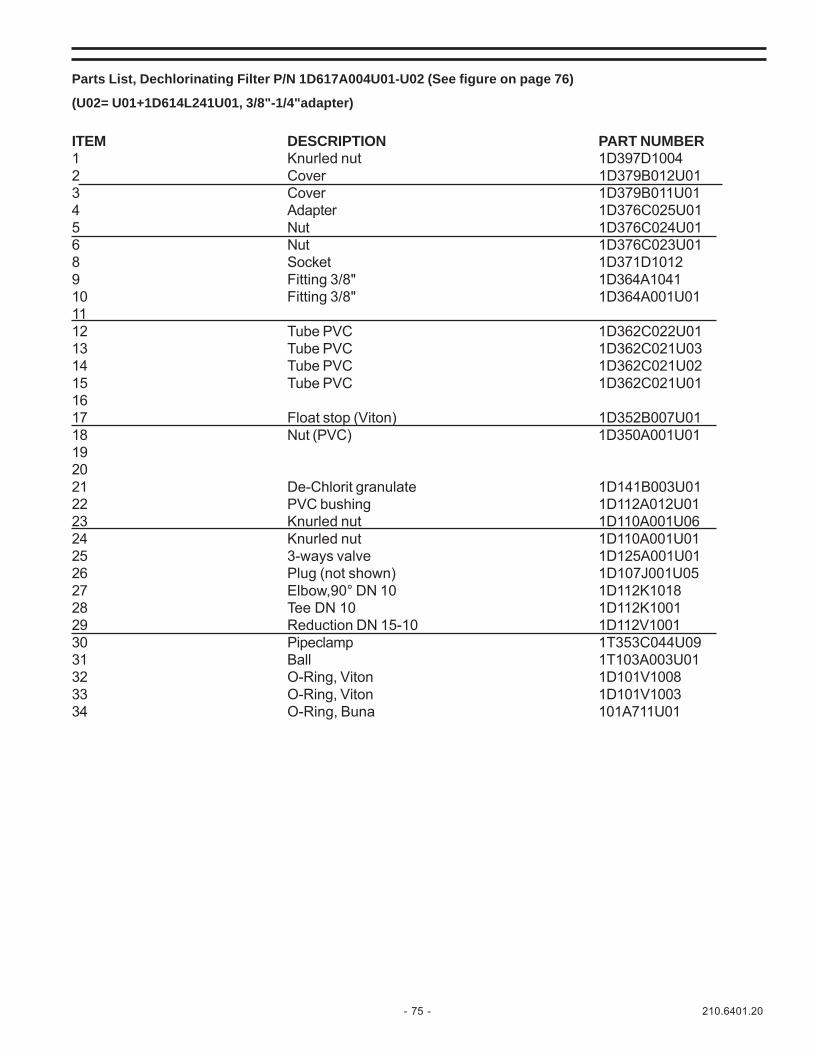
- 75 - 210.6401.20
Parts List, Dechlorinating Filter P/N 1D617A004U01-U02 (See figure on page 76)
(U02= U01+1D614L241U01, 3/8"-1/4"adapter)
ITEM DESCRIPTION PART NUMBER1 Knurled nut 1D397D10042 Cover 1D379B012U013 Cover 1D379B011U014 Adapter 1D376C025U015 Nut 1D376C024U016 Nut 1D376C023U018 Socket 1D371D10129 Fitting 3/8" 1D364A104110 Fitting 3/8" 1D364A001U011112 Tube PVC 1D362C022U0113 Tube PVC 1D362C021U0314 Tube PVC 1D362C021U0215 Tube PVC 1D362C021U011617 Float stop (Viton) 1D352B007U0118 Nut (PVC) 1D350A001U01192021 De-Chlorit granulate 1D141B003U0122 PVC bushing 1D112A012U0123 Knurled nut 1D110A001U0624 Knurled nut 1D110A001U0125 3-ways valve 1D125A001U0126 Plug (not shown) 1D107J001U0527 Elbow,90° DN 10 1D112K101828 Tee DN 10 1D112K100129 Reduction DN 15-10 1D112V100130 Pipeclamp 1T353C044U0931 Ball 1T103A003U0132 O-Ring, Viton 1D101V100833 O-Ring, Viton 1D101V100334 O-Ring, Buna 101A711U01
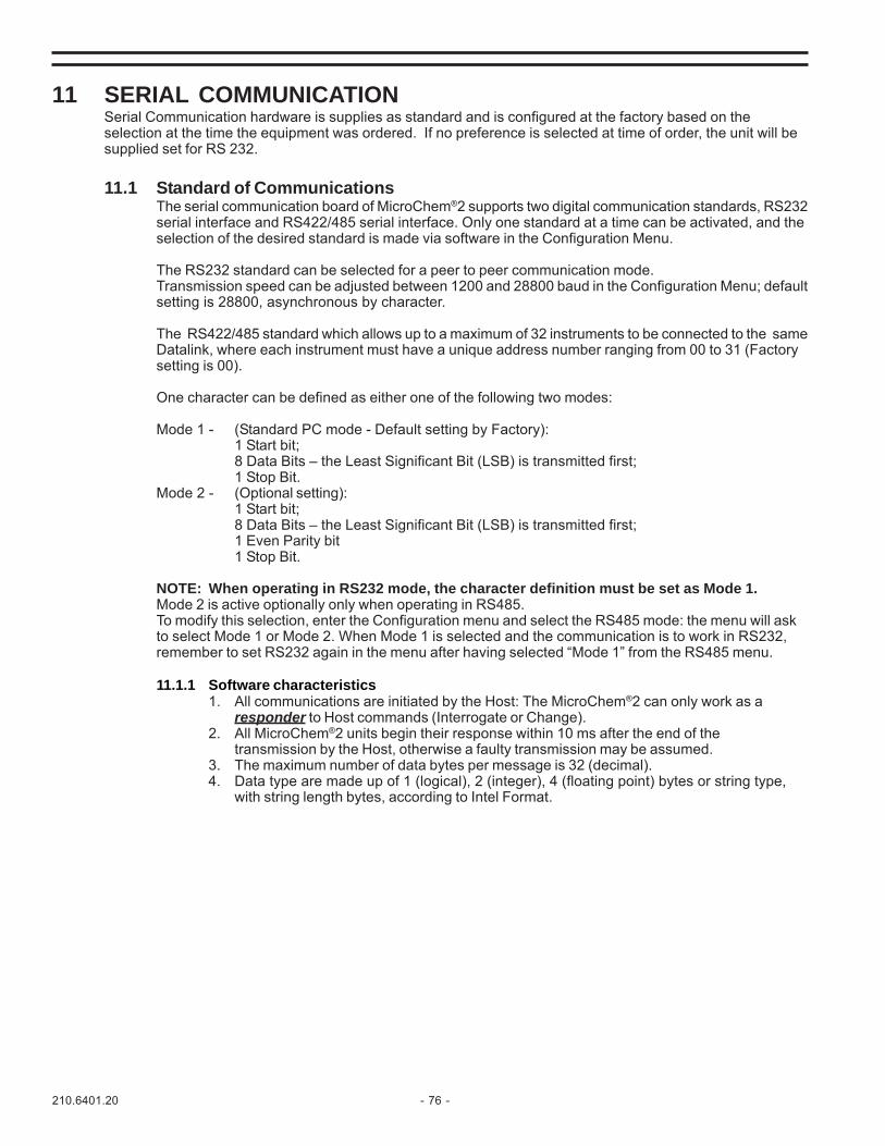
210.6401.20 - 76 -
11 SERIAL COMMUNICATIONSerial Communication hardware is supplies as standard and is configured at the factory based on theselection at the time the equipment was ordered. If no preference is selected at time of order, the unit will besupplied set for RS 232.
11.1 Standard of CommunicationsThe serial communication board of MicroChem®2 supports two digital communication standards, RS232serial interface and RS422/485 serial interface. Only one standard at a time can be activated, and theselection of the desired standard is made via software in the Configuration Menu.
The RS232 standard can be selected for a peer to peer communication mode.Transmission speed can be adjusted between 1200 and 28800 baud in the Configuration Menu; defaultsetting is 28800, asynchronous by character.
The RS422/485 standard which allows up to a maximum of 32 instruments to be connected to the sameDatalink, where each instrument must have a unique address number ranging from 00 to 31 (Factorysetting is 00).
One character can be defined as either one of the following two modes:
Mode 1 - (Standard PC mode - Default setting by Factory):1 Start bit;8 Data Bits – the Least Significant Bit (LSB) is transmitted first;1 Stop Bit.
Mode 2 - (Optional setting):1 Start bit;8 Data Bits – the Least Significant Bit (LSB) is transmitted first;1 Even Parity bit1 Stop Bit.
NOTE: When operating in RS232 mode, the character definition must be set as Mode 1.Mode 2 is active optionally only when operating in RS485.To modify this selection, enter the Configuration menu and select the RS485 mode: the menu will askto select Mode 1 or Mode 2. When Mode 1 is selected and the communication is to work in RS232,remember to set RS232 again in the menu after having selected “Mode 1” from the RS485 menu.
11.1.1 Software characteristics1. All communications are initiated by the Host: The MicroChem®2 can only work as a
responder to Host commands (Interrogate or Change).2. All MicroChem®2 units begin their response within 10 ms after the end of the
transmission by the Host, otherwise a faulty transmission may be assumed.3. The maximum number of data bytes per message is 32 (decimal).4. Data type are made up of 1 (logical), 2 (integer), 4 (floating point) bytes or string type,
with string length bytes, according to Intel Format.
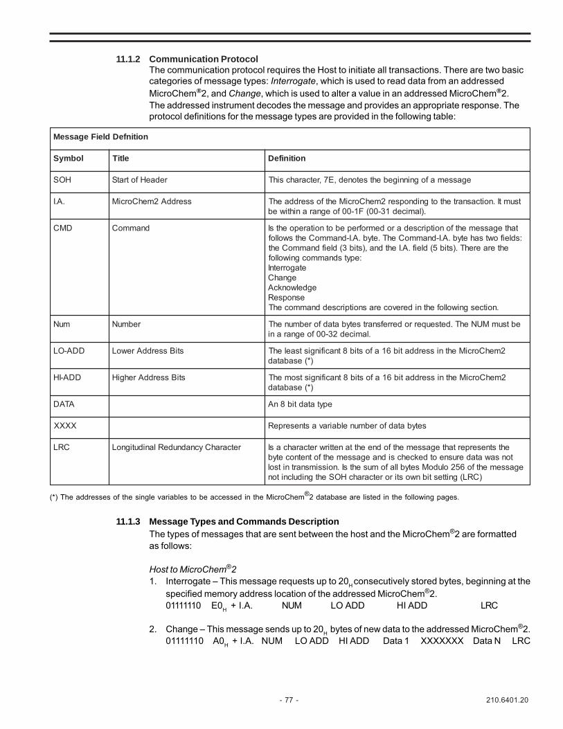
- 77 - 210.6401.20
11.1.2 Communication ProtocolThe communication protocol requires the Host to initiate all transactions. There are two basiccategories of message types: Interrogate, which is used to read data from an addressedMicroChem®2, and Change, which is used to alter a value in an addressed MicroChem®2.The addressed instrument decodes the message and provides an appropriate response. Theprotocol definitions for the message types are provided in the following table:
(*) The addresses of the single variables to be accessed in the MicroChem®2 database are listed in the following pages.
11.1.3 Message Types and Commands DescriptionThe types of messages that are sent between the host and the MicroChem®2 are formattedas follows:
Host to MicroChem®21. Interrogate – This message requests up to 20H consecutively stored bytes, beginning at the
specified memory address location of the addressed MicroChem®2.01111110 E0H + I.A. NUM LO ADD HI ADD LRC
2. Change – This message sends up to 20H bytes of new data to the addressed MicroChem®2.01111110 A0H + I.A. NUM LO ADD HI ADD Data 1 XXXXXXX Data N LRC
noitinfeDdleiFegasseM
lobmyS eltiT noitinifeD
HOS redaeHfotratS egassemafogninnigebehtsetoned,E7,retcarahcsihT
.A.I sserddA2mehCorciM tsumtI.noitcasnartehtotgnidnopser2mehCorciMehtfosserddaehT.)lamiced13-00(F1-00foegnaranihtiweb
DMC dnammoC tahtegassemehtfonoitpircsedarodemrofrepebotnoitarepoehtsI:sdleifowtsahetyb.A.I-dnammoCehT.etyb.A.I-dnammoCehtswollof
ehteraerehT.)stib5(dleif.A.Iehtdna,)stib3(dleifdnammoCeht:epytsdnammocgniwollof
etagorretnIegnahC
egdelwonkcAesnopseR
.noitcesgniwollofehtniderevocerasnoitpircseddnammocehT
muN rebmuN ebtsumMUNehT.detseuqerroderrefsnartsetybatadforebmunehT.lamiced23-00foegnarani
DDA-OL stiBsserddArewoL 2mehCorciMehtnisserddatib61afostib8tnacifingistsaelehT)*(esabatad
DDA-IH stiBsserddArehgiH 2mehCorciMehtnisserddatib61afostib8tnacifingistsomehT)*(esabatad
ATAD epytatadtib8nA
XXXX setybatadforebmunelbairavastneserpeR
CRL retcarahCycnadnudeRlanidutignoL ehtstneserpertahtegassemehtfodneehttanettirwretcarahcasItonsawataderusneotdekcehcsidnaegassemehtfotnetnocetyb
egassemehtfo652oludoMsetybllafomusehtsI.noissimsnartnitsol)CRL(gnittestibnwostiroretcarahcHOSehtgnidulcniton

210.6401.20 - 78 -
3. Acknowledge – This message signals the addressed MicroChem®2 that it’s last echoedchange message was received correctly; the MicroChem®2 performs the change requested.01111110 80H + I.A.
MicroChem®2 to Host1. Response – This message furnishes the data requested by the INTERROGATE command of
the Host. It is also used to echo back the previous CHANGE message of the Host. 01111110 20H + I.A. NUM LO ADD HI ADD Data 1 XXXXXXX DataN LRC
11.2 Communication Transaction Examples11.2.1 Transaction A Example
Host requests 9 bytes of data beginning at hexadecimal memory address 1000H from theMicroChem®2 at datalink address 03:
1. Host sends interrogate message:01111110 11100011 00001001 00000000 00010000 11111100SOH Command NUM LO ADD HI ADD LRC
+ I.A.2. MicroChem®2 sends response message:
01111110 00100011 00001001 00000000 00010000 XXXX XXXX XXXX LRCSOH Command NUM LO ADD HI ADD Data 1.... Data 9+ I.A.
11.2.2 Transaction B ExampleHost sends two bytes of new data, to be loaded into the MicroChem®2 at datalink address 03beginning at hexadecimal memory address 1000 H:Host sends change message:01111110 101000011 00000010 00000000 00010000 00001000 00001100 11001001SOH Command NUM LO ADD HI ADD Data 1 Data 2 LRC+ I.A.1. MicroChem®2 sends response message:
01111110 00100011 00000010 00000000 00010000 00001000 00001100 01001001SH Command NUM LO ADD HI ADD Data 1 Data 2 LRC+ I.A.
2. Host sends acknowledge message:01111110 10000011SOH Command I.A.
3. MicroChem®2 performs the change requested at end of the current program scan.Note: Database address table is shown at the end of this section.
11.3 Serial link signal connectionThe MicroChem®2 optional serial communication PC Board is equipped with a modular RJ11 jack.
TUO-YALKCAJNOITCENNOCLANGISENOHPELET11JR
.oNniP 232SR 224SR 584SR
1 DNGdnuorG
DNGdnuorG dnuorG-DNG
2 ataDNIXRCPmorfnoissimsnarT
+xT+,CPotnoissimsnartataD -
3 TUOxTCPotnoissimsnartataD
-xT-,CPotnoissimsnartataD -xRxT
4 - +xR+,CPmorfnoissisnartataD -xRxT
5 - -xR-,CPmorfnoissimsnartataD -
6 dnuorGDNG dnuorG-DNG dnuorG-DNG

- 79 - 210.6401.20
Figure 18 – RJ11 Cable Pin Designation
For RS232 and RS485 use 18 AWG (0.5 - 1.0 mm2) shielded and twisted pair wire.For RS422 use shielded cable, 18 AWG (0.5 - 1.0 mm2) 4-conductor or two (2) twisted pair wires.Connect shields to the ground shield terminal strip inside the MicroChem®2.
11.4 DATALINK TERMINATORThe Datatlink impedance should be 110 ohms.
When the serial communication standard is selected as RS422 or RS485, and more than one MicroChem®2are installed on the same datalink, it is necessary to activate a terminator resistance, which is available on theserial communication board.
This operation is to be made only on the last MicroChem®2 connected on the serial link.
If the host computer serial port is already equipped with a resistor, then an identical resistor is to be activatedin parallel to obtain a 110 ohms loop impedance. If no such resistor is present on the Host side, then a 110ohms resistor is selected on the MicroChem®2 serial board.
The terminator resistance selection is made by installing a jumper on JP1 or JP2 for RS422 or RS485respectively: the 110 ohms resistor is selected by jumper between the center pin and pin 1, while the 220ohms resistor is selected by jumper between the center pin and pin 2.
Figure 19 – RJ11 Connector and Terminator Resister Link Layout
JP1 – RS422 Data Link Terminator
JP2 – RS485 Data Link Terminator
RS232 Jumpers 1, 2, 3RS485 Jumpers 6, 7, 8RS422 Jumpers 4, 5, 6, 7, 8
1
6
JP1 (RS422)
JP2 (RS485)
1
2
2
1
220 ohms 110ohms
220 ohms 110 ohms
RJ11 Cable
61

210.6401.20 - 80 -
11.5 MicroChem®2 Memory MapIncrement: (figures between brackets ‘[x]’ indicate the number of similar variables repeated).
Char type: 1 byteint type: 2 bytesfloat type: 4 bytesstring type: 1 byte x string length
Type Hex addr. Name Description int 0X0000 PgmMode Program mode (0-4) Transmitter, Washing, Regulator… int 0X0002 Lng Language in usechar 0X0004 AccCode[6] MicroChem®2 Passwordchar 0X000A TermAddr[4] Serial line addressint 0X000E SerSpeed Serial line speedint 0X0010 SerType Serial line typefloat 0X0012 Altitude Altitude where MicroChem®2 is mountedint 0X0016 CCIinOR Set for CCI in OR modeint 0X0018 Average Set for Average countfloat 0X001A Delta Delta limitfloat 0X001E pH_offset[3] Offset for PH (SPC), for 3 channelsfloat 0X002A P1[3] Calibration P1 value for 3 channelsfloat 0X0036 P2[3] Calibration P2 value for 3 channelsfloat 0X0042 P1U[3] User Calibration P1 value for 3 channelsfloat 0X00AE P2U[3] User Calibration P2 value for 3 channelsint 0X005A Light Set when backlight is ONint 0X005C T_Units Temperature unitsfloat 0X005E DefTemp Default temperature for temperature compensationint 0X0062 AltUnits Altitude Units meters/feetint 0X0064 Sigma Sigma enabled or notfloat 0X0066 sK1 Sigma K1 parameterfloat 0X006A sK2 Sigma K2 parameterfloat 0X006E Hyst[3] Smoothing for each channelint 0X007A wType Wash Type T17AU / T17SUchar 0X007C wT[4][9] Wash Timers T1-T4float 0X00A0 Out_LO[3] Min. output value for 3 channelsfloat 0X00AC Out_HI[3] Max. output value for 3 channelsint 0X00B8 DacType[3] Type of DAC outputfloat 0X00BE AlLO[3] Alarms low levelfloat 0X00CA AlHI[3] Alarms high levelfloat 0X00D6 AlBA[3] Alarms Bandint 0X00E2 DO_AIR[3] Set when DO is in airint 0X00E8 Reserved Reserved
0X0108 SerMode Type of RS485/422 serial lineint 0X010A CIO 0 = No I/O Board, 1 = Yes I/O Boardchar 0X010C DoWash When set, TX has washingchar 0X010D PidType Determine program PID modechar 0X010E Reservedchar 0X010F Reservedchar 0X110 mA type chn [3]char 0X113 Reservedfloat 0X114 mA span [3]float 0X120 mA offset [3]int 0X012C Ena[3] Channels enabledint 0X0132 Type[3] Channel types

- 81 - 210.6401.20
PID 1 DATA int 0X0150 Reserved float 0X0152 PB Proportional Band float 0X0156 TR Reset Time float 0X015A MR Manual Rest float 0X015E TD Rate Time float 0X0162 SETPOINT Set Point float 0X0166 CONTROLZONE Control Zone int 0X016A RSW Direct/Reverse Action float 0X016C SPAN Span int 0X0170 OHLP float 0X0172 FF HIGH float 0X0176 FF LOW float 0X017A FF ABS MAX float 0X017E FF GAIN float 0X0182 OH float 0X0186 OL int 0X018A TATP float 0X018C K float 0X0190 TATT float 0X0194 TCYC float 0X0198 LH float 0X019C LL float 0X01A0 PH BAND int 0X01A4 TIME CYCLE float 0X01A6 CONTACT GAIN float 0X01AA DZ int 0X01AE 1C/2C int 0X01B0 PA
Table 20 - PID1 Data Memory Map
PID 2 DATA int 0X01B2 Reserved float 0X01B4 PB Proportional Band float 0X01B8 TR Reset Time float 0X01BC MR Manual Rest float 0X01C0 TD Rate Time float 0X01C4 SP Set Point float 0X01C8 CZ Control Zone int 0X01CC RSW Direct/Reverse Action float 0X01CE SPAN Span float 0X01D2 OH High Limit float 0X01D6 OL Low Limit int 0X01DA TATP Sampling on entire trim or volume float 0X01DC K Flowmeter span float 0X01E0 TATT float 0X01E4 TCYC float 0X01E8 LH float 0X01EC LL int 0X01F0 CT float 0X01F2 CG float 0X01F6 DZ int 0X01FA CONTACT int 0X01FC PA
Table 21 - PID2 Data Memory Map
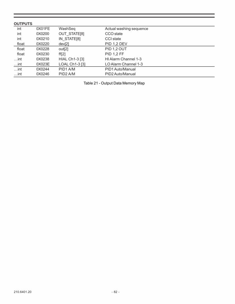
210.6401.20 - 82 -
OUTPUTS int 0X01FE WashSeq Actual washing sequence int 0X0200 OUT_STATE[8] CCO state int 0X0210 IN_STATE[8] CCI state float 0X0220 dev[2] PID 1,2 DEV float 0X0228 out[2] PID 1,2 OUT float 0X0230 ff[2] PID 1,2 FF…int 0X0238 HIAL Ch1-3 [3] HI Alarm Channel 1-3…int 0X023E LOAL Ch1-3 [3] LO Alarm Channel 1-3…int 0X0244 PID1 A/M PID1 Auto/Manual…int 0X0246 PID2 A/M PID2 Auto/Manual
Table 21 - Output Data Memory Map

- 83 - 210.6401.20
12 APPENDICES12.1 EC DECLARATION - APPENDIX I
EC DECLARATION
MicroChem®2 line (T17M*4000) fulfills the compliance to the mandatory tests specified by the applicable harmonisedgeneric rules to apply the CE Mark, according to European Directive 89/336/EEC and subsequent modifications.
As the final environment may be industrial or residential, the test was performed according to the worst-case test set(industrial test for immunity, residential test for emission). For CE Mark, owing to both the residential and industrialenvironment applications, the reference rules are the following “Generic Standards”:
• CENELEC EN 50081-1/1992 (CEI 110-7) Electromagnetic compatibility - Generic emission standard - Part 1: residential,commercial and light industry
• CENELEC EN 50082-1/1992 (CEI 110-8) Electromagnetic compatibility - Generic immunity standard - Part 1: residential,commercial and light industry
• CENELEC EN 50081-2/1993 (CEI 110-13) Electromagnetic compatibility - Generic emission standard - Part 2: industrialenvironment
• CENELEC EN 50082-2/1995 (CEI 110-25) Electromagnetic compatibility - Generic immunity standard - Part 2: industrialenvironment
TSET NOITPIRCSED SLEVEL
22055NE noissimedetcudnoC BssalC
22055NE noissimedetaidaR BssalC
4-4-00016NE dnagnitseT:4traP-ytilibitapmoccitengamortcelEtsaflacirtcelE:4noitceS-seuqinhcettnemerusaem
tsetytinummitsrubtneisnart
;elbacrewopnopVk2=MC;elbaclatigid/golanaO/InopVk2=MC
elbaclairesnopVk1-=MC
5-4-00016NE gnitseT:4traP-ytlibitapmoccitengamortcelE-seuqinhcettnemerusaemdnatsetytinummiegruS:5noitceS
elbacrewopnopVk2=MD,PVk4=MCelbaclatigid/golanaO/InopVk1=MD,pVk2=MC
6-4-00016NE dnagnitseT:4traP-ytilibitapmoccitengamortcelE-seuqinhcettnemerusaem
oidarybdecudnisecnabrutsiddetcudnoC:6noitceStsetytinummisdleifycneuqerf
zHk1MA.dom+smV01=MCzHM032-zHk051egnaR
11-4-00016NE snoitautculfegatloV %01nV
11-4-00016NE dnagnitseT:4traP-ytilibitapmoccitengamortcelE,spidegatloV:11noitceS-seuqinhcettnemerusaem
tsetytinummisnoitairavegatlovdnasnoitpurretnitrohs
s5rof%001-sm01rof%03-
sm001rof%06-
3-4-00016NE gnitseT:4traP-ytilibitapmoccitengamortcelE-seuqinhcettnemerusaemdna
dleifcitegamortceleycneuqerf-oidar,detaidaR:3noitceStsetytinummi
zHk1MA.dom+m/smrV01
2-4-00016NE dnagnitseT:4traP-ytilibitapmoccitengamortcelEseuqinhcettnemerusaem
tsetytinummiegrahcsidcitatsortcelE:2noitceS
pVk4=DC,pVk8=DA
8-4-00016NE dnagnitseT:4traP-ytilibitapmoccitengamortcelE:8noitceS-seuqinhcettnemerusaem
tsetytinummidleifcitengamycneuqerfrewoP
m/A03
MicroChem®2 line (T17M*4000B) also fulfils the compliance to the EN61010-1 rules.

210.6401.20 - 84 -
STEP BY STEP SIMPLIFIED INSTRUCTIONS USING CL4000 PROBES:Please Refer to 4.3 Channel DefinitionThe keys used to define the channels are:
ABC – moves you laterally through the software
Enter – moves you down into the software holding the Enter key is also used to display an alarm condition.
End – moves you up in the software. End is also used to toggle the process display conditions from channels 1, 2, 3 ifthey are installed
The following procedure is to configure the instrument to analyze Chlorine on channel 1 and Chlorine on channel 2,using CL4000 probes
Press ABC, see Password:/ Flashing Cursor
Type in 00000
Press Enter, see ------ Menu Mode ------/ Menu
Press ABC, see ------ Menu Mode ------/Calibration
Press ABC until you see - Menu Mode/Channel Definition
Press Enter, see Channel Definition/ Channel 1
Press Enter see Channel 1/ CL
Press ABC until you see Channel 1/CL. (Continual pressing of ABC will rotate/move you laterally through the variousparameters that the MicroChem2 is capable of measuring CL, CD, T, mA, F, Br, NH3, NO3, pH, O2, mV, and O3.NOTE: mA allows you to drill down another level. Then pressing ABC will rotate/move you laterally through mA, %,ppm, mg/l, g/h, L/s, L/h, m3/h, °C, °F, μS, mS, Kpa, Mpa, PSI, GPM, GPD, MGD, NTU, FTU, m, ft, in.)
Press Enter, see CL/ KC4000 Cell
Press ABC, see CL/CL probe [mA]
Press Enter, see CL Settings/ 4mA = 0.00ppm (This is the low range of your chlorine probe)
Press Enter and Enter 00.00. You will see a flashing cursor.
Press Enter, see CL Settings 20mA = 10.00 ppm
Press Enter, see Channel Definition/ Channel 1
Press ABC, see Channel Definition/ Channel 2
Press Enter, see Channel 2/ CL
Press Enter, see CL/KC4000 Cell
Press ABC, see CL/CL Probe [mA]
Press Enter see Channel 2/ Mode TX
Press Enter, see CL Settings/ 4mA = 0.00 ppm
Press Enter, see the flashing cursor and enter 0000
Press Enter, see CL Settings/ 20mA = 10 ppm
Press Enter, see the flashing cursor, enter the upper limit of the range for the Chlorine probe on Channel 2.
Press Enter, see Channel Definition/Channel 2.
Press End three times and see the display for what is being measured on channel 1
Continual pressing of the End key will toggle through the process measurement screens for the number of channelsthat are installed and configured
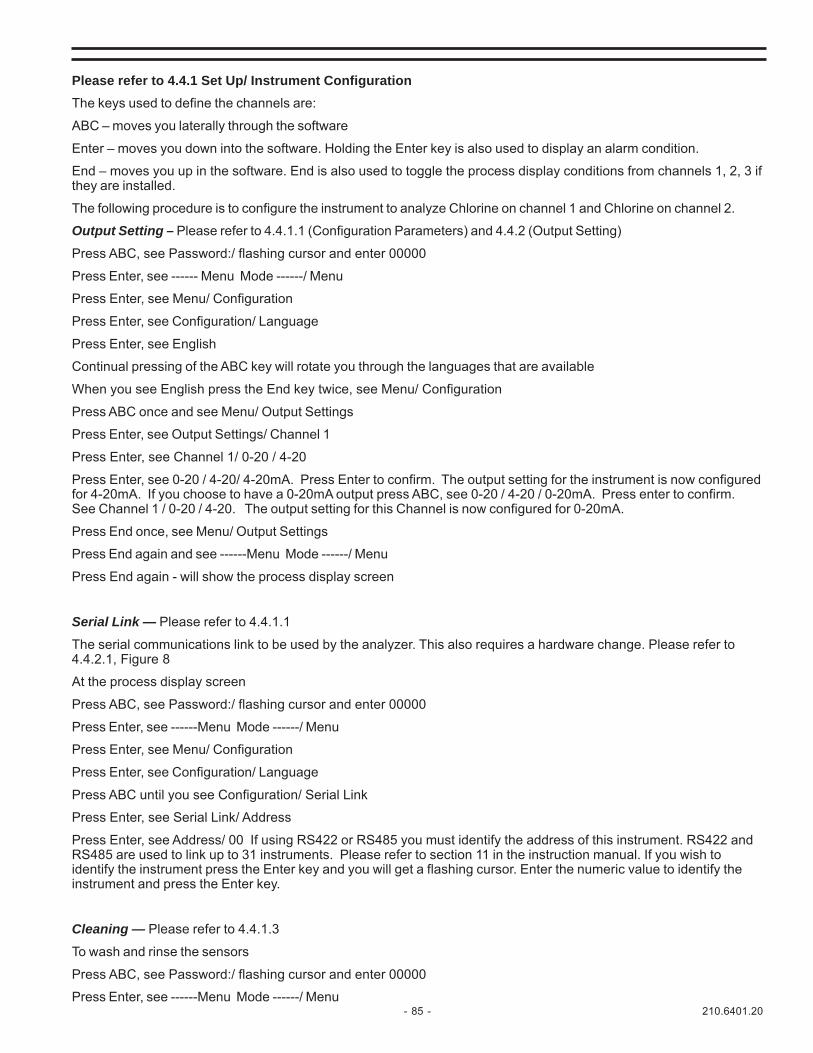
- 85 - 210.6401.20
Please refer to 4.4.1 Set Up/ Instrument ConfigurationThe keys used to define the channels are:
ABC – moves you laterally through the software
Enter – moves you down into the software. Holding the Enter key is also used to display an alarm condition.
End – moves you up in the software. End is also used to toggle the process display conditions from channels 1, 2, 3 ifthey are installed.
The following procedure is to configure the instrument to analyze Chlorine on channel 1 and Chlorine on channel 2.
Output Setting – Please refer to 4.4.1.1 (Configuration Parameters) and 4.4.2 (Output Setting)
Press ABC, see Password:/ flashing cursor and enter 00000
Press Enter, see ------ Menu Mode ------/ Menu
Press Enter, see Menu/ Configuration
Press Enter, see Configuration/ Language
Press Enter, see English
Continual pressing of the ABC key will rotate you through the languages that are available
When you see English press the End key twice, see Menu/ Configuration
Press ABC once and see Menu/ Output Settings
Press Enter, see Output Settings/ Channel 1
Press Enter, see Channel 1/ 0-20 / 4-20
Press Enter, see 0-20 / 4-20/ 4-20mA. Press Enter to confirm. The output setting for the instrument is now configuredfor 4-20mA. If you choose to have a 0-20mA output press ABC, see 0-20 / 4-20 / 0-20mA. Press enter to confirm.See Channel 1 / 0-20 / 4-20. The output setting for this Channel is now configured for 0-20mA.
Press End once, see Menu/ Output Settings
Press End again and see ------Menu Mode ------/ Menu
Press End again - will show the process display screen
Serial Link — Please refer to 4.4.1.1
The serial communications link to be used by the analyzer. This also requires a hardware change. Please refer to4.4.2.1, Figure 8
At the process display screen
Press ABC, see Password:/ flashing cursor and enter 00000
Press Enter, see ------Menu Mode ------/ Menu
Press Enter, see Menu/ Configuration
Press Enter, see Configuration/ Language
Press ABC until you see Configuration/ Serial Link
Press Enter, see Serial Link/ Address
Press Enter, see Address/ 00 If using RS422 or RS485 you must identify the address of this instrument. RS422 andRS485 are used to link up to 31 instruments. Please refer to section 11 in the instruction manual. If you wish toidentify the instrument press the Enter key and you will get a flashing cursor. Enter the numeric value to identify theinstrument and press the Enter key.
Cleaning — Please refer to 4.4.1.3
To wash and rinse the sensors
Press ABC, see Password:/ flashing cursor and enter 00000
Press Enter, see ------Menu Mode ------/ Menu

210.6401.20 - 86 -
Press Enter, see Menu/Configuration
Press Enter, see Configuration/Language
Press ABC until you see Configuration/Cleaning
Press Enter, see Cleaning/Activate
Press Enter, see Activate/NO
Press ABC, see Activate/Yes
Press Enter, see Cleaning/Activate
Press ABC - see Cleaning/A or B, You must choose B.
Press Enter - see A or B/A
Press ABC - see A or B/A
Press ABC - see A or B/B
Press Enter - see Cleaning A or B
Press ABC - see Cleaning/Cleaning T1. This is the time period between the end of a cleaning sequence and the starttime of the next one.
Press Enter - see Cleaning T1/00:00:00. This represents hours, minutes and seconds between cleanings.
Press Enter - see Cleaning T1/flashing cursor
Insert desired time between cleanings
Press Enter - see Cleaning/Cleaning T1
Press ABC - see Cleaning/Cleaning T2
Press Enter - see Cleaning T2/00:00:00. This represents the length of time for washing. Hours have no meaning.You can set cleaning to 30 minute maximum.
Press Enter - see Cleaning T2/flashing cursor
Insert desired time per T2
Follow the same sequence for T3 (Rinse Time) and T4 (Pause Time after cleaning for sensor recovery sensibility) ifneeded
Continual pressing of the End Key will bring you back to the process measuring display
Temperature Select °C or °F— Please refer to 4.4.1.1
Press ABC, see Password:/ flashing cursor and enter 00000
Press Enter, see ------Menu Mode ------/ Menu
Press Enter, see Menu/ Configuration
Press Enter, see Configuration/ Language
Press ABC until you see Configuration/ Temp. Select
Press Enter, see Temp. Select/ °C, another press of the ABC key will toggle you to °F
Press End until you see Menu/ Configuration
Temperature Set — Please refer to 4.4.1.1
This is a safety feature to tell the instrument the temperature to be used if the thermistor is faulty
Press ABC, see Password:/ flashing cursor and enter 00000
Press Enter, see ------Menu Mode ------/ Menu
Press Enter, see Menu/ Configuration
Press Enter, see Configuration/ Language
Press ABC until you see Configuration/ Temp. Set

- 87 - 210.6401.20
Press Enter, see Temp. Set/ 20.00
Press Enter, see Temp. Set/ with the flashing cursor. Enter the value of the temperature you wish
Press the End Key until you return back to the process measurement display
Altitude (only used for Dissolved Oxygen) — Please refer to 4.4.1.1
This only appears when one of the channels is defined O2
Press ABC, see Password:/ flashing cursor and enter 00000
Press Enter, see ------Menu Mode ------/ Menu
Press Enter, see Menu/ Configuration
Press Enter, see Configuration/ Language
Press ABC until you see Configuration/ Altitude
Press Enter, see Altitude/ Eng. Unit Set
Press Enter, see Eng. Unit Set/ Meters by pressing ABC, and Enter you can select altitude in feet rather than meters
Press Enter see Altitude/ Eng. Unit Set
Press ABC, see Altitude/ Set Value
Press Enter, see Set Value/ Ft = 656.20
Press Enter, see Set Value/ Ft = 656.20 with a flashing cursor
Enter the altitude at your plant location and press Enter
Press the End Key until you return back to the process measurement display
CCI in OR — Please refer to 4.4.1.1
This function is used during cleaning to freeze the display.
Press ABC, see Password:/ flashing cursor and enter 00000
Press Enter, see ------Menu Mode ------/ Menu
Press Enter, see Menu/ Configuration
Press Enter, see Configuration/ Language
Press ABC until you see Configuration/ OR CCI
Press Enter, see OR CCI/ NO
Press ABC, see OR CCI/ YES and press Enter to freeze the display of the analyzer.
Press the End key until you return back to the process measurement display
Average — Please refer to 4.4.1.1
This function is used if you have a 2 or a 3 channel instrument and 2 of the channels are configured to test the sameparameter.
Press ABC, see Password:/ flashing cursor and enter 00000
Press Enter, see ------Menu Mode ------/ Menu
Press Enter, see Menu/ Configuration
Press Enter, see Configuration/ Language
Press ABC until you see Configuration/ Average
Press Enter, see Average/ NO
Pressing the ABC key will let you toggle between Average/ NO and Average/ Yes
Press the End key until you return back to the process measurement display

210.6401.20 - 88 -
Delta — Please refer to 4.4.1.1
This function is used with 2 channel transmitters when both channels are configured to test the same parameter. It willcause an alarm if the difference between the two channels is greater than the set value.
Press ABC, see Password:/ flashing cursor and enter 00000
Press Enter, see ------Menu Mode ------/ Menu
Press Enter, see Menu/ Configuration
Press Enter, see Configuration/ Language
Press ABC until you see Configuration/ Delta
Press Enter, see Delta/ 0.000
Press Enter to see the flashing cursor and enter the desired Delta value31
Press Enter, see Configuration/ Delta
Press the End key until you return back to the process measurement display
Smoothing — Please refer to 4.4.1.1
This function lessens the degree of measurement fluctuation seen on the display
Press ABC, see Password:/ flashing cursor and enter 00000
Press Enter, see ------Menu Mode ------/ Menu
Press Enter, see Menu/ Configuration
Press Enter, see Configuration/ Language
Press ABC until you see Configuration/ Smoothing
Press Enter, see Smoothing/ Channel 1. Press ABC to toggle between channels
Press Enter, see Channel 1/ 1.00.
Press Enter to see the flashing cursor. Set the smoothing to 30. This is a good place to start.
Press Enter to see Confirm, see Smoothing/Channel 1.
Press the End key until you return back to the process measurement display
Digital Input and Digital Output Settings — Please refer to 4.4.1.1 and 4.4.2
Each analyzer has 2 digital inputs CCI 1 and CCI 2. Each analyzer also has 7 digital outputs also referred to as DigitalRelay Contact Closures. Each input and output is configured separately as normally opened (NO) or normally closed(NC).
Press ABC, see Password: / flashing cursor and enter 00000
Press Enter, see ------Menu Mode ------/ Menu
Press Enter, see Menu/ Configuration
Press Enter, see Configuration/ Language
Press ABC until you see Configuration/ Digital I/O Set
Digital Outputs:
Press Enter, see Digital I/O Set/ Digital Outputs
Press Enter, see Digital Outputs/ Ch. 1
Press ABC to rotate through channels 1 through 7 (CCO1 through CCO7)
Press Enter, see Ch. 1/ NO. Toggle between NO and NC by pressing the ABC key

- 89 - 210.6401.20
Digital Inputs:
Press End until you see Digital I/O Set/ Digital Outputs. Press the ABC key to toggle between Digital Inputs and DigitalOutputs
Press Enter, see Digital Inputs/ Ch. 1
Press ABC to toggle between channels 1 and 2
Press Enter, see Ch. 1/ NO. Toggle between NO and NC by pressing the ABC key
Setting Alarms - Please refer to 4.4.3
The keys used to set the alarms are:
ABC – moves you laterally through the software
Enter – moves you down into the software. Enter is also used to display an alarm condition.
End – moves you up in the software. End is also used to toggle the process display conditions from channels 1, 2, 3 ifthey are installed
The Alarms Menu is used to set the alarms for each parameter the instrument is capable of analyzing. Alarms defaultto the default settings in 4.4.3 Table 4.
Low and High AlarmsTo change the alarm settings:
Press ABC, see Password: / flashing cursor and enter 00000
Press Enter, see ------Menu Mode ------/ Menu
Press Enter, see Menu/ Configuration
Press ABC key to rotate to Alarms
Press Enter, see Alarms/ Channel 1
Press Enter, see Channel 1/ Low Alarm
Press Enter, see Low Alarm/ 1.000
Press Enter to see the flashing cursor and enter the desired low alarm value
Press the End Key see Menu/ Alarms
Press Enter, see Alarms/ Channel 1
Press Enter, see Channel 1/ Low Alarm
Press ABC, see Channel 1/ High Alarm
Press Enter, see High Alarm/ 9.000
To change the High Alarm press Enter and the flashing cursor will appear. Enter the desired value.
Press the End key until the measuring process display appears
Dead Band – Please refer to 4.4.3
Dead Band is used to avoid the alarms from oscillating around the Lo and Hi alarm set points
Press ABC, see Password: / flashing cursor and enter 00000
Press Enter, see ------Menu Mode ------/ Menu
Press Enter, see Menu/ Configuration
Press ABC until you see Menu/ Alarms
Press Enter, see Alarms/ Channel 1
Press Enter, see Channel 1/ Low Alarm

210.6401.20 - 90 -
Press ABC until you rotate to Dead band
Press Enter, see Dead band/ 0.000
Press Enter, see Dead band/0.000 with the flashing cursor. Enter the desired value. Then press the End key until themeasuring process display appears
ANALYZER CALIBRATION
The following procedure is to configure the instrument to analyze Chlorine on channel 1 and Chlorine on channel 2
The keys used to calibrate the instrument are
ABC – moves you laterally through the software
Enter – moves you down into the software. Enter is also used to display an alarm condition
End – moves you up in the software. End is also used to toggle the process display conditions from channels 1, 2, 3 ifthey are installed
Probe Calibration - General - Please refer to 6.1.1 for Calibration Menu
Calibration - Please refer to 6.1.5 for Chlorine Calibration
Press ABC, see Password:/ Flashing Cursor. Insert 00000
Press Enter, see ------Menu Mode ------/ Menu
Press ABC, until you see ------Menu Mode ------/Calibration
Press Enter, see Calibration/ Channel 1
Press Enter, see Channel 1/ Calibration P1
NOTE: P1calibration is only necessary for the initial calibration to set the zero point. When performing recalibration it isonly necessary to set the P2; skip to the P2 calibration (4 lines below)
Press Enter, see the low calibration value/ P1: 0.000
Press Enter, see the flashing cursor and enter the calibration value (for your low sample that has been stripped ofchlorine using a carbon filter)
Press Enter, see Channel 1/ Calibration P1
Press ABC, see Channel 1/ Calibration P2
Press Enter, see the high chlorine calibration value/ P2: 10.00
Press Enter, see the flashing cursor and enter the P2 value based on testing such as with DPD or titration
Press Enter, see Channel 1/ Calibration P2:
Press Enter, see the measurement value XX.XX CL (for the process )/ P2: YY.YY (the P2 value entered)
Press End 4 times to take you to the process measurement display
AUTOMATIC CONTROL METHODS:
A. RESIDUAL PID CONTROLLER PROPORTIONAL BAND (PB) - Please refer to 5.2.2, Table 8.
1. Press ABC key – see Password with a flashing indicator. Press Zero Key and enter 00000.
2. Press Enter, see ------ Menu Mode ------/ Menu
3. Press Enter, see Menu/Configuration
4. Press ABC and scroll to Menu / Controller
5. Press Enter to Controller / PID 1
6. Press Enter, see PID1 General/ 4-20 / Contacts
7. Press Enter, see 4-20 / Contacts / 4-20 mA. This is the default. In order to use the general PID parameters, the instrument must be set to 4-20.

- 91 - 210.6401.20
8. Press Enter, see PID / General 4-20 / Contacts
9. Press ABC, see PID1 General/ PB
10. Press Enter, see PB/100. This is the default for PB.
11. Press Enter again to get the flashing cursor to allow you to change the Proportional Band.
12. Insert 250, press Enter and see PID1 General/ PB
TIME RESET/INTEGRAL ACTION (TR) - Please refer to 5.2.2, Table 8
13.Press ABC, see PID1 General/ TR m/r
14. Press Enter see TR m/r / 0.00
15. Press Enter to show the flashing cursor
16. Enter the previously determined TR value. If a higher number than the range is inserted, the instrument defaults to 30 minutes
17. Press Enter to confirm the value and see PID1 General/ TR m/r
MANUAL RESET (MR) - Please refer to 5.2.2.1, Table 8
18. Press ABC and see PID1 General/ MR %
Skip this function. Manual reset is rarely used. To use Manual Reset you must set TR = 0. It represents the output ofthe controller when the PV is in the Control Zone; when the PV is almost equal to the Set Point.
DERIVATIVE ACTION (TD) - Please refer to 5.2.2.1, Table 8
19. Press ABC and see PID1 General/ TD m
Skip this function, it is rarely used. It is used to allow for sudden changes in the PV
PROCESS VARIABLE (PV) - Please refer to 5.2.2.1, Table 8
20. Press ABC and see PID1 General/ PV
21. Press Enter and see PID1 PV: the analysis and the current Process Variable will be indicated at the top left of the display
22. Press End and see PID1 General/ PV
SET POINT (SP) - Please refer to 5.2.2.1, Table 8
23. Press ABC and see PID1 General/ SP
SP is the Set Point for the desired PV
24. Press Enter and see SP/ 0.00
25. Press Enter to see the flashing cursor and enter the desired Set Point for the PV based on the analysis performed (at the wet end of the analyzer and just before the fall out) when determining your TR value. Please refer to 5.2.2.1 Integral Action (TR).
26. Press Enter and see PID1 General/ SP
NOTE: The Set Point can be adjusted manually using the blue buttons.

210.6401.20 - 92 -
CONTROL ZONE (CZ) - Please refer to 5.2.2.1, Table 8
27. Press ABC and see PID1 General/ CZ
Control Zone is used to avoid continuous control adjustments for small fluctuations from Set Point. Please refer to5.2.2.1 for an explanation of Control Zone
28. Press Enter twice to see the flashing cursor and enter the desired value
29. Press Enter and see PID1 General/ CZ
DIRECT/REVERSE ACTION (RSW) - Please refer to 5.2.2.1 for an explanation of DIRECT/REVERSE ACTION (RSW).
30. Press ABC and see PID1 General/ RSW D/R
31. Press Enter and see RSW D/R/ Reverse
32. Press Enter to confirm and see PID1 General/ RSW D/R
SPAN - Range of Wet End
33. Press ABC and see PID1 General/ SPAN
34. Press Enter and see SPAN/ X.XX – see the numeric indication of the process variable.
35. Press Enter to see the flashing cursor and enter the desired range for the controller based on (in the case of chlorine using a CL4000 probe) the range of the probe
36. Press Enter to confirm and see PID1 General/ SPAN
HIGH LIMIT OUTPUT (OH)
37. Press ABC and see PID1 Limits/ OH%
38. Press Enter and see OH%/ 100.00
39. Press Enter again and see the flashing cursor, and enter the upper limit of the process
40. Press Enter to confirm and see PID1 Limits/ OH %
LOW LIMIT OUTPUT (OL)
41. Press ABC and see PID1 Limits/ OL %
42. Press Enter and see OL%/ 0.00
43. Press Enter to see the flashing cursor. Insert the desired low limit
44. Press Enter to confirm and see PID1 Limits/ OL%
45. Press End until you return to the process analysis/controller screen
Once the Process Variable is running as desired press the Blue 5 Key to switch to Automatic Mode
A.FEED FORWARD ACTION - Please refer to 5.2.2.2
Limit output as a function of Flowrate (OHLP)
A 2 channel unit is required
Channel 2 must previously have been configured as mA and further defined as mode PID

- 93 - 210.6401.20
B.FEED FORWARD CONTROL - Please refer to 5.2.2.2
1. Press ABC, see Password/flashing cursor and enter 00000
2. Press Enter, see ------Menu Mode ------/ Menu
3. Press Enter, see Menu/Configuration
4. Press ABC, see Menu/Controller
5. Press Enter, see Controller/PID1
6. Press Enter, see PID General/4-20/Contacts
7. Press ABC, see PID1 General/PB. Continue to press ABC until PID1 Feed Flow/OHLP NO/YES appears on the display
8. Press Enter, see OHLP NO/YES/NO
9. Press ABC, see OHLP NO/YES/YES. OHLP must be set to Yes to limit the output as a function of the flow rate.
FACTOR TO COMPUTE MAX OUTPUT BASED ON FLOWRATE (GFFH) - Please refer to 5.2.2.2
10.Press Enter, see PID1 Feed Forw./OHLP NO/YES
11.Press ABC, see PID1 Feed Forw./FFH
12.Press Enter, see FFH 1.50. This is the default
13.Press Enter, see FFH/flashing cursor
14.Enter the desired numeric value
15.Press Enter, see PID1 Feed Forward/FFH
FACTOR TO COMPUTE MINIMUM OUTPUT BASED ON FLOWRATE VALUE (FFL) - Please refer to 5.2.2.2
16.Press ABC, see PID1 Feed Forward/FFL
17.Press Enter, see FFL 0.50. This is the default value
18. Press Enter, see FFL/flashing cursor
19. Enter the desired numeric value
20.Press Enter, see PID1 Feed Forward/FFL
ABSOLUTE HIGH LIMIT ON OUTPUT WHEN LIMITS BASED ON FLOWRATE ARE ACTIVE (MAX. ABS) - Please referto 5.2.2.2
21. Press ABC, see PID1 Feed Forward/Absolute Max
22.Press Enter, see Absolute Max/100.00. This is the default value
23.Press Enter, see Absolute Max/flashing cursor
24.Enter the desired Absolute Max value
25.Press Enter, see PID1 Feed Forward/Absolute Max.
GAIN FACTOR APPLIED ON FLOW RATE SIGNAL (GAIN) - Please refer to 5.2.2.2
26.Press ABC, see PID1 Feed Forward/Gain
27.Press Enter, see Gain/100.00. This is the default value
28.Press Enter, see Gain/flashing cursor
29.Enter the desired value
30.Press Enter, see PID1 Feed Forw./Gain

210.6401.20 - 94 -
31.Press End until you return to the process analyzer/controller screen32.Once the process is running as desired, press the Blue 5 Key to switch to automatic mode.
C. TIME SAMPLING OR FLOW-PACING CONTROLLER (TATP)- Please refer to 5.2.2.3
Define Channel 1 as chlorine or another parameter. The 4-20 mA output provides PID control. The analog input for Channel2 must be configured to 4-20 mA and further configured to mode PID.
TIME SAMPLING (TATP) - Please refer to 5.2.2.3.1
1. Press ABC, see Password:/flashing cursor and Enter 00000.
2. Press Enter, ---Menu Mode---/ Menu
3. Press Enter, see Menu/Configuration
4. Press ABC, see Menu/Controller
5. Press Enter, see Controller/PID1
6. Press Enter, see PID1 General/4-20/Contacts
7. Press ABC until you see PID1 Chlorine/TATP NO/YES
8. Press Enter, see TATP NO/YES/NO
9. Press ABC, see TATP NO/YES/YES
10.Press Enter, see PID1/Chlorine/TATP NO/YES, then OH and OL are not engaged, Absolute Max is used.
SCALING FACTOR FOR FLOW (K) - Please refer to 5.2.2.3.2
11.Press ABC, see PID1 Chlorine (if configured)/K
12.Press Enter, see K/O.O. This is the default value. K is not used in Time Sampling.
13.Press End and see PID1 Chlorine (if configured as such)/K
ACTIVE TIME (ATT) - Please refer to 5.2.2.3.1
14.Press ABC, see PID 1 Chlorine/ATT.
15.Press Enter, see ATT/0.00. This is the default value.
16.Press Enter, see ATT/flashing cursor.
17.Enter the desired numeric value
18.Press Enter, see PID1 Chlorine/ATT (if configured as such)
CYCLE (FOR FLOW) - Please refer to 5.2.2.3.2
19.Press ABC, see PID1 Chlorine/Cycle
20.Press Enter, see Cycle/0.00. This is the default value.
21.Press Enter, see Cycle/flashing cursor.
22.Enter the desired Cycle time.
23.Press Enter, see PID1 Chlorine/Cycle.
24.Press End until you return to the process analyzer/controller screen.
25.Once the process is running as desired, press the Blue 5 key to switch to automatic mode.
D. COMPOUND LOOP CONTROLLER - Please refer to 5.2.2.4
Channel 1 must be defined as chlorine - Please refer to 4.3
All PID parameters must be set except TD and MR - Please refer to 5.2.2.1
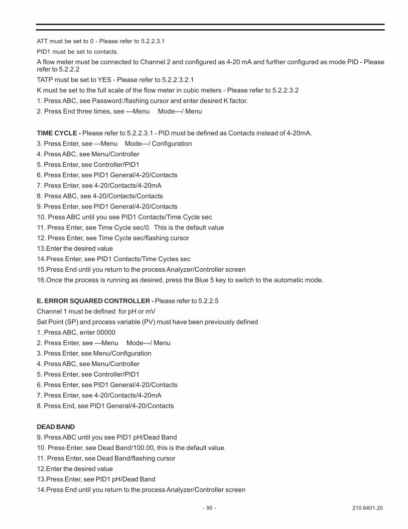
- 95 - 210.6401.20
ATT must be set to 0 - Please refer to 5.2.2.3.1
PID1 must be set to contacts.
A flow meter must be connected to Channel 2 and configured as 4-20 mA and further configured as mode PID - Pleaserefer to 5.2.2.2TATP must be set to YES - Please refer to 5.2.2.3.2.1K must be set to the full scale of the flow meter in cubic meters - Please refer to 5.2.2.3.21. Press ABC, see Password:/flashing cursor and enter desired K factor.2. Press End three times, see ---Menu Mode---/ Menu
TIME CYCLE - Please refer to 5.2.2.3.1 - PID must be defined as Contacts instead of 4-20mA.3. Press Enter, see ---Menu Mode---/ Configuration4. Press ABC, see Menu/Controller5. Press Enter, see Controller/PID16. Press Enter, see PID1 General/4-20/Contacts7. Press Enter, see 4-20/Contacts/4-20mA8. Press ABC, see 4-20/Contacts/Contacts9. Press Enter, see PID1 General/4-20/Contacts10. Press ABC until you see PID1 Contacts/Time Cycle sec11. Press Enter, see Time Cycle sec/0. This is the default value12. Press Enter, see Time Cycle sec/flashing cursor13.Enter the desired value14.Press Enter, see PID1 Contacts/Time Cycles sec15.Press End until you return to the process Analyzer/Controller screen16.Once the process is running as desired, press the Blue 5 key to switch to the automatic mode.
E. ERROR SQUARED CONTROLLER - Please refer to 5.2.2.5Channel 1 must be defined for pH or mVSet Point (SP) and process variable (PV) must have been previously defined1. Press ABC, enter 000002. Press Enter, see ---Menu Mode---/ Menu3. Press Enter, see Menu/Configuration4. Press ABC, see Menu/Controller5. Press Enter, see Controller/PID16. Press Enter, see PID1 General/4-20/Contacts7. Press Enter, see 4-20/Contacts/4-20mA8. Press End, see PID1 General/4-20/Contacts
DEAD BAND9. Press ABC until you see PID1 pH/Dead Band10. Press Enter, see Dead Band/100.00, this is the default value.11. Press Enter, see Dead Band/flashing cursor12.Enter the desired value13.Press Enter, see PID1 pH/Dead Band14.Press End until you return to the process Analyzer/Controller screen

210.6401.20 - 96 -
F. CONTACT OUTPUT CONTROLLER - Please refer to 5.2.2.6
1. Press ABC, see Password:/flashing cursor and enter 00000
2. Press Enter, see ---Menu Mode---/ Menu
3. Press Enter, see Menu/Configuration
4. Press ABC, see Menu/Controller
5. Press Enter, see Controller/PID1
6. Press Enter, see PID1 General/4-20/Contacts
7. Press Enter, see 4-20/Contacts/4-20mA
8. Press ABC, see 4-20/Contacts/Contacts
9.Press Enter, see PID1 General/4-20/Contacts
10.Press End twice, see Menu/Controller
11.Press Enter, see Controller/PID1
12.Press Enter, see PID1 General/4-20/Contacts
GAIN - Please refer to 5.2.2.6
13.Press ABC until you see PID1 Contacts/Gain
14.Press Enter, see Gain 1.00, this is the default value.
15.Press Enter, see Gain/flashing cursor
16.Enter the desired Gain value.
17.Press Enter, see PID1 Contacts/Gain
DEAD ZONE (DZ) - Please refer to 5.2.2.6
18.Press ABC, see PID/Contacts/DZ
19.Press Enter, see DZ/0.00, this is the default value.
20.Press Enter, see DZ/flashing cursor
21.Enter the desired value.
22.Press Enter, see PID1 Contacts/DZ
TIME CYCLE - Please refer to 5.2.2.6
23.Press ABC, see PID1 Contacts/Time Cycle Sec
24.Press Enter, see Time Cycle sec 10, this is the default value.
25.Press Enter, see Time Cycle sec/flashing cursor
26.Enter the desired value
27.Press Enter, see PID1 Contacts/Time Cycle sec
28.Press the End key until you return to the process Analyzer/Controller screen.

- 97 - 210.6401.20
THIS PAGE INTENTIONALLY LEFT BLANK

210.6401.20 - 98 -
A MicroChem®2 Analyzer/Transmitter Software Menu Tree - APPENDIX II
NCNO
ChannelDigital Inputs
NCNO
ChannelDigital Outputs
Digital I/O Set1.00
ChannelSmoothing
(enter value)(multichannel units with two or more identical channels)Delta
YesNo(multichannel units with two or more identical channels)Average
OffYesNo
OR CCI20.00
Temp SetFC
Temp SelectCleaning T4Cleaning T3Cleaning T2Cleaning T1
BA (not used)
A or BYesNo
Activate(when cleaning software option is installed)CleaningSerial PortBaud RateAddress
Serial Link00000 (Default)
PasswordSpanishGermanFrenchEnglishItalian
Language
Configuration
Menu

- 99 - 210.6401.20
A MicroChem®2 Analyzer/Transmitter Software Menu Tree - APPENDIX II (continued)
In W ater (D issolved Oxygen)In A ir (D issolved Oxygen)
Calibration P2Calibration P1S.P.C . (pH)
ChannelCalibration
m ABr
CD20mA4m ACl probe (mA)
KC4000 cellC lF
ChannelChannel Definition
DeadbandH igh AlarmLow A larm
ChannelA larms
O ut SpanO ut Zero0-20/4-20
ChannelO utput Settings
(Factory use only)E lectric Calib.Channel
O utput SignalsChannel
Input S ignalsAnalog I/O
O utput SignalsInput S ignals
D igital I/OD isplay TestKeyboard Test
Instrum ent Test
UNITS AVAILABLE: m A, % , ppm ,m g/l, gr/h, l/s , l/h, m 3/h, °C , °F,µS, m S, Kpa, Mpa, PSI, G PM,G PD, MG D, NTU, FTU, m , ft, in
pHm VO 2O 3
TIndependantEqual to 1st channel
(2 or 3 channel units)
4m A20mA
IndependantEqual to 1st channelT
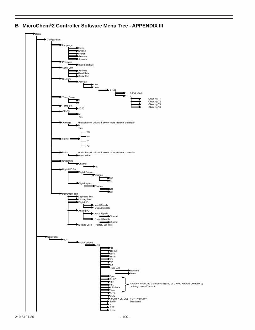
210.6401.20 - 100 -
B MicroChem®2 Controller Software Menu Tree - APPENDIX III
CycleATT.K
DeadbandTATPif CH1 = pH, mV(if CH1 = CL, CD)
OL%OH%GainABS MAX
Available when 2nd channel configured as a Feed Forward Controller bydefining channel 2 as mA.
FFLFFHOHLPSpan
DirectReverse
RSW D/RCZSPPVTD mMR%TR m/rPB
4-204-20/Contacts
PID 1Controller
(Factory use only)Electric Calib.Channel
Output SignalsChannel
Input SignalsAnalog I/O
Output SignalsInput Signals
Digital I/ODisplay TestKeyboard Test
Instrument TestNCNO
ChannelDigital Inputs
NCNO
ChannelDigital Outputs
Digital I/O Set15
ChannelSmoothing
(enter value)(multichannel units with two or more identical channels)Delta
YesNo(multichannel units with two or more identical channels)Average
YesNo
OR CCI20.00
Temp SetFC
Temp Select
Cleaning T4Cleaning T3Cleaning T2Cleaning T1
BA (not used)
A or BYesNo
ActivateCleaning
Serial PortBaud RateAddress
Serial Link00000 (Default)
PasswordSpanishGermanFrenchEnglishItalian
Language
Configuration
Menu
Sigma
Yes
No
K1
K2

- 101 - 210.6401.20
B MicroChem®2 Controller Software Menu Tree (contintued)
20mA4mA
mg/l, gr/h, l/s, l/h, m3/h, °C, °F,UNITS AVAILABLE: mA, %, ppm,
ChannelChannel Definition
In Water (Dissolved Oxygen)In Air (Dissolved Oxygen)
Calibration P2Calibration P1S.P.C. (pH)
ChannelCalibration
DeadbandHigh AlarmLow Alarm
ChannelAlarms
Out SpanOut Zero0-20/4-20
ChannelOutput Settings
mA
µS, mS, Kpa, Mpa, PSI, GPM,GPD, MGD, NTU, FTU, m, ft, in
MODE TXMODE PID
pHmVO2O3
FCl
CDT
Br
KC4000 cellCl probe (mA) 4mA
20mA
1
SEE SECTION 5.2.2.2.
MODE PID ALLOWS INSTRUMENT TO ADJUST CONTROL SIGNAL BASED ON FLOW RATE AND THE MEASURED VALUE OF THE PROCESS.
MODE TX ALLOWS THE MEASUREMENT OF THE OTHER UNITS AVAILABLE WHEN CHANNEL 2 IS DEFINITED AS mA.
NOTE 1: ONLY APPEARS ON CHANNEL 2.
MODE TXMODE PID
CH2IndependantTo 1st channel
1
1
(2 or 3 channel units)
Equal to 1st channelIndependant
1
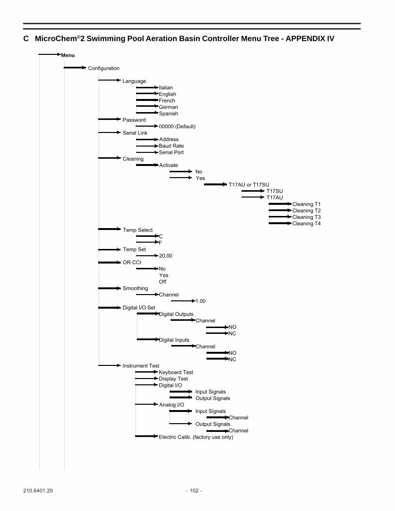
210.6401.20 - 102 -
C MicroChem®2 Swimming Pool Aeration Basin Controller Menu Tree - APPENDIX IV
Electric Calib. (factory use only)Channel
Output SignalsChannel
Input SignalsAnalog I/O
Output SignalsInput Signals
Digital I/ODisplay TestKeyboard Test
Instrument TestNCNO
ChannelDigital Inputs
NCNO
ChannelDigital Outputs
Digital I/O Set1.00
ChannelSmoothing
OffYesNo
OR CCI20.00
Temp SetFC
Temp SelectCleaning T4Cleaning T3Cleaning T2Cleaning T1
T17AUT17SU
T17AU or T17SUYesNo
ActivateCleaning
Serial PortBaud RateAddress
Serial Link00000 (Default)
PasswordSpanishGermanFrenchEnglishItalian
Language
Configuration
Menu

- 103 - 210.6401.20
C MicroChem®2 Swimming Pool Aeration Basin Controller Menu Tree (continued)
In Water (Dissolved Oxygen)In Air (Dissolved Oxygen)
Calibration P2Calibration P1S.P.C. (pH)
ChannelCalibration
Equal to 1stIndependent(2 or 3 channel units only)Temperature
mV
20mA4mACl probe (mA)
KC4000 cellClChannel 2
pHChannel 1
Channel Definition
DeadbandHigh AlarmLow Alarm
ChannelAlarms
Out SpanOut Zero0-20/4-20
Output Settings
CycleATT.K
noyes
TATP Number of PulsesPID1 ChlorineLow LimitOL%GainOH%
FrequencySpanTime Cycle secDirectDZReverseGainRSW D/R
RelaysCZDigital Ouputs SPpH DeadbandPVSPANTD mRSW D/RMR%SPTR m/rPVPB
4-204-20ContactsContacts
4-20/Contacts4-20/ContactsPID 2PID 2
Number of PulsesDeadbandLow LimitOL%GainOH%
FrequencySpanTime Cycle secDirectDZReverseGainRSW D/R
RelaysCZDigital Ouputs SPpH DeadbandPVSPANTD mRSW D/RMR%SPTR m/rPVPB
4-204-20ContactsContacts
4-20/Contacts4-20/ContactsPID 1PID 1
Controller

210.6401.20 - 104 -07/07
Represented by:Design improvements may be made without notice.
Severn Trent Services (UK)Park Lane, Minworth,Sutton Coldfield, West Midlands, B76 9BLTel +44 (0) 121 313 2300Fax +44 (0) 121 313 [email protected]
Severn Trent Services3000 Advance Lane Colmar, PA 18915Tel: 215-997-4000 • Fax: 215-997-4062Web: www.severntrentservices.comE-mail: [email protected]
Copyright 2004 Severn Trent Services