INSTRUCTION MANUAL - IOC AG7 …phoenix.tuwien.ac.at/chemistry/Gebrauchsanweisungen/SAVANT...
27
INSTRUCTION MANUAL 1 SCl 10 SPEEDVAC? CONCENTRATOR 3 SC110A/SC2 10A SPEEDVAP PLUS CONCENTRATORS SAVANT ltVSTRUKElWS, MC. 100 Colin Drive Holbrook. NY 1 1741-4306 1-800-634-8886(5 16)244-2929 Fax: (516) 244-0606
Transcript of INSTRUCTION MANUAL - IOC AG7 …phoenix.tuwien.ac.at/chemistry/Gebrauchsanweisungen/SAVANT...
INSTRUCTION MANUAL
1 SCl 10 SPEEDVAC? CONCENTRATOR
3 SC110A/SC2 10A SPEEDVAP PLUS CONCENTRATORS
SAVANT ltVSTRUKElWS, MC. 100 Colin Drive Holbrook. NY 1 174 1-4306
1-800-634-8886 (5 16) 244-2929 Fax: (516) 244-0606
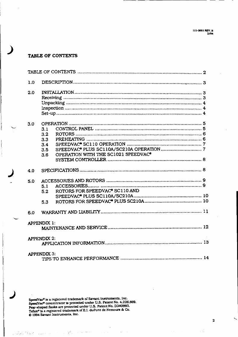
.......................................................................................... TABLE OF CONTENTS 2
............................................................................................. I 1.0 DESCRIPTION 3
............................................................................................ 2.0 INSTALLATION 3 Receiving .................................................................................................. 3 Unpacking ............................................................................................ 4 Inspection ............................................................................................ 4 Set-up ......................................................................................................... 4
I ! 3.0 OPERATION ........................................................................................... 5 ~~ L 3.1 C0Nl"ROLPANEL ............................................................................ 5 ........................................................................................... 3.2 ROTORS 6
I ................................................................................... 3.3 PREHEATING 6 ...................................................... 3.4 SPEEDVA C. SC 1 10 OPERATION 7
............................. 3.5 SPEEDVACO PLUS SC110A/SC2 10A OPERATION 7 ! 3.6 OPERATION WITH THE SC1021 SPEEDVAC?
SYSTEM CONTROLLER ................................................................ 8
........................................................................................ 4.0 SPECIFICATIONS 8
..................................................................... .. 5.0 ACCESSORIES AND ROTORS 9 5.1 ACCESSORIES ................................................................................. 9 5.2 ROTORS FOR SPEEDVACO SC 1 10 AND
........................ ................ SPEEDVA C. PLUS SC 1 1OA/SC2 10A ... 10 ......................................... 5.3 ROTORS FOR SPEEDVA C. PLUS SC2 10A 10
......................................................................... 6.0 w m AND LIABILITY 11 L
APPENDIX 1: .................................................................... M m N A N C E AND SERVICE 12
APPENDIX 2: ...................................................................... APPLICATION INFORMATION 13
APPENDIX 3: ................................... TIPS TO ENHANCE PERFORMANCE .................... 14 ~
I
I SpeedVu? is a regFsted bademark of Savant Insrrummts. Inc . 1 SpcdVar concenrrator is protected under U.S. Patent No . 4.226.669.
Pear-shaped k k s are protected unda U.S. Patent No . D340993 . Tellon* is a registered trademark of E.I. duPont de Nemoun & Co . O 1944 Savant InsIruments . Inc .
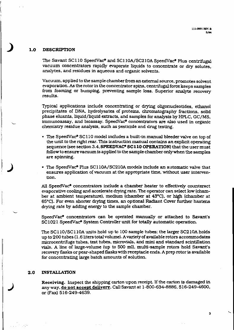
) 1.0 DESCRIPTION
The Savant SC 1 10 SpeedVae and SC 1 10A/SC2 10A SpeecTVae Plus centrifugal vacuum concentrators rapidly evaporate liquids to concentrate or dry solutes. analytes, and residues in aqueous and organic solvents.
Vacuum. applied to the sample chamber kom an external source. promotes solvent evaporation. As the rotor in the concentrator spins. centrifugal force keeps samples from foaming or bumping. preventing sample loss. Superior anal* recovery results.
I ?Lpical applications include concentrating or dqmg oligonucleotides. ethanol
I precipitates of DNA. hydrolysates of proteins. chromatography fractions, solld phase eluants. llquid/liquid extracts. and samples for analysis by HPLC. GC/MS.
I
I irnmunoassay, and bioassay. SpeedVar? concentrators are also used in organic chemistry residue analysis, such as pesticide and drug testing.
The SpeedVaP SC 1 10 model includes a built-in manual bleeder valve on top of the unit to the right rear. This instruction manual contains an explicit operating sequence (see section 3.4. SPEEDVACo SC110 OPERATION) that the user must follow to ensure vacuum is applled to the sample chamber only when the samples are spinning.
The SpeedVae Plus SC110A/SC210A models include an automatic valve that ensures application of vacuum at the appropriate time. without user interven- tion.
All SpeedVae concentrators include a chamber heater to effectively counteract evaporative cooling and accelerate drylng rate. The operator can select low (cham- ber at ambient temperature), medium (chamber at 43OC). or high (chamber at 65°C). For wen shorter drying times, an optional Radiant Cover further hastens drying rate by adding energy to the sample chamber.
L
SpeedVae concentrators can be operated manually or attached to Savant's SC 102 1 SpeedVae System Controller unit for totally automatic operation.
The SC 1 10/SC 1 10A units hold up to 100 sample tubes: the larger SC2 10A holds up to 200 tubes (1.6 liters total volume). Avariety of available rotors accommodates microcentrifuge tubes. test tubes, microvials. and mini and standard scintillation vials. A line of large-volume (up to 500 ml). multl-sample rotors hold Savant's recovery flasks or pear-shaped flasks with receptacle ends. A prep rotor is available for concentrating large batch amounts of solution.
2.0 INSTAUATION
Receiving. Inspect the shipping carton upon receipt. If the carton is damaged in any way. do not accept delivem. Call Savant at 1-800-634-8886.516-2494600. or (Fax) 516-249-4639.
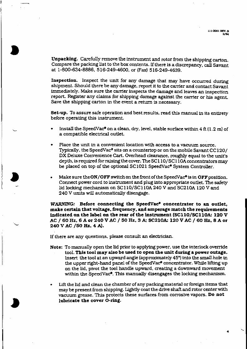
Unpacking. Carefully remove the instrument and rotor from the shipping carton. Compare the packing list to the box contents. If there is a discrepancy, call Savant at 1-800-634-8886. 5 16-249-4600. or (Fax) 5 16-249-4639.
Inspection. Inspect the unit for any damage that may have occurred during shipment. Should there be any damage. report it to the carrier and contact Savant immediately. Make sure the carrler inspects the damage and leaves an inspection report. Register any claims for shipping damage against the carrier or his agent. Save the shipping carton in the event a return is necessary.
Set-up. To assure safe operation and best results. read this manual in its entirety before operating this instrument.
Install the SpeedVaP on a clean. dry. level. stable surface within 4 R (1.2 m) of a compatible electrical outlet.
Place the unit in a convenient location with access to a vacuum source. ?Lpically. the SpeedVae sits on a countertop or on the mobile S a w t CC 120/ DX Deluxe Convenience Cart. Overhead clearance. roughly equal to the unit's depth. is required for raising the cover. The SC 1 10/SC 1 10A concentrators may be placed on top of the optional SC 102 1 SpeedVaP System Controller.
. Make sure theON/OFF switch on the front of the SpeedVaP is in OFFposition. Connect power cord to instrument and plug into appropriate outlet. The safety lid locking mechanism on SC 1 10/SC 1 10A 240 V and SC2 10A 120 V and 240 V units will automatically disengage.
W-G: Before connecting the Speedvat9 concentrator to an outlet, make certain that voltage. frequency. and amperage match the requirements indicated on the label on the rear of the instmment (SCllO/SCllOk 120 V AC/60Hz. 6Aor240VAC/50HzV 3k'SCZlOk 120VAC/60Hz,SAor 240 V AC /50 HZ, 4 A].
If there are any questions, please consult an electridan.
Note: To manually open the lid prior to applying power. use the interlock override tool. This tool may also be used to open the unit during a power outage. Insert the tool at an upward angle (approximately 45") into the small hole in the upper right-hand panel of the SpeedVaP concentrator. While lifting up on the lid. pivot the tool handle upward, creating a downward movement within the SpeedVaP. This manually disengages the locking mechanism.
Lit the lid and clean the chamber of any packing material or foreign items that may be present from shipping. Lightly coat the drive shaft and rotor centerwith vacuum grease. This protects these surfaces from corrosive vapors. Do not lubricate the cover O-ring.
Attach the concentrator to a vacuum system (vapor trap plus vacuum pump). Read this entire section before proceeding:
Generaldirections. Connect the 0.5 inch (1.27 cm) O.D. hose fitting at the rear of the unit to the vacuum system. Coat fitting with a thin film of vacuum grease. Thread vacuum tubing through the hole in the instrument right side panel. Without twisting, carefully push vacuum tubing straight on over fitting.
Note: Read the Reconfiguration section of this manual (see APPENDIX 2, page 13) before disconnecting or replacing vacuum hose.
Protecting the vacuum DumD. Avacuum pump experiences loss of eflGciency and ultimate damage if evaporated solvents from samples are allowed to enter. To prevent damage and extend pump life, a vapor trap that condenses and preferably freezes solvent vapors must be placed in-line between the SpeedVace concentrator andvacuum pump. A complete line of vacuum pumps and refrigerated vapor traps is available from Savant.
A chemical trap. placed in-line between the vapor trap and the vacuum pump. further protects the pump from any vapors pulled through the trap. Savant's SCTl2O Chemical Trap may be used with the DC120A cartridge to adsorb aqueous vapors and neutralize corrosive acid vapors. or with the DC 120R cartridge to adsorb radioactivity and volatile organic vapors.
System configuration may vary depending on the needs. preferences. and application requirements of the user. If uncertain of the optimal set-up. call Savant Technical Services at 1-800-634-8886.516-249-4600. or Faxl5 16-249- 4639 for additional information.
3.0 OPERATION
The SpeedVac? or Speedvat9 Plus concentrator is an important component in a sample drymg/concentration system that should also include vacuum gauge. refrigerated vapor trap. chemical trap, and vacuum pump. and may contain other equipment. Please refer to operating instructions of each component for details on use.
3.1 CONTROL PANEL
Two switches on the instrument front panel govern operation of the Speedvat9 SC 1 10/SC 1 10A/SC2 10A concentrators:
The CONCENTRATOR switch controls rotation (ON/Om. The DRYING RATE switch regulates sample chamber temperature (HIGH/MEDIUM/LOW.
Indicator lights illuminate when a function is switched on. \
5

3.2 ROTORS
A wide variety of SpeedVar rotors is available to suit every sample drytng application. These rotors are designated by the RH prefix followed by numbers denoting vial capacity and tube dfameter. For example. the RH100-6 rotor accommodates 100 tubes of 6 rnm diameter. Also available are horizontal rotor heads [HRH prefi) for swing-out carriers. microplate rotors w R / M P T R prefix]. and a prep rotor [PREP-1001 for batch pro- cessing.
CAUTION: Only these rotor series should be used in the SpeedVaco. DO NOT use other rotors. even if they seem to fit the instrument.
CAUTION: Always balance rotor loads. An unbalanced rotor causes vibration that will wear out the bearings and may seri- ously damage the SpeedVaco.
Load the rotor uniformly. There need not be a tube in each place. but the tubes must be evenly spaced around the rotor. When using a rotor with aluminum tube holders. insert tube holders symmetrically. When drying different types of sample in the same drying m. distribute each type symmetrically so that their different dryrng rates do not introduce preces- sion into the rotor's rotation. Always select a rotor into which the sample tubes fit snugly.
To install or change a rotor:
Venfy that CONCENTRATOR switch is in OFF position.
Open the lid. Unscrew the rotor hold-down knob and remove the existing rotor (if any). Select desired replacement rotor. Align the notches in the rotor base with the drive pin of the motor shaft. Place the rotor on the s h e be sure the pins engage the notches. Hand-tighten the rotor hold-down knob until firmly seated.
3.3 PREHEATING
Evaporative sample cooling that occurs under vacuum actually decreases sample drying rate. The sample chamber heater counteracts this effect to accelerate dryrng rate. If desired. operate the DRYING RATE switch a t least 15 minutes before starting the concentration run.
LOW leaves the chamber a t ambient temperature (1.e.. chamber heater is om. MEDIUM heats the chamber to 43°C. HIGH heats the chamber to 65°C.
3.4 SPEEDVACm SC 110 OPERATION
Load samples symmetrically. Venfy that the rotor is frrmly seated and the hold-down knob is hand-tight. Close the cover and set the CONCENTRA- TOR switch to ON. Allow rotor to reach full speed (approximately 20 seconds) before manually applying vacuum with the bleeder valve. This valve exposes spinning samples in the sample chamber to vacuum from the vacuum system and. at the end of the run, bleeds the chamber back to atmospheric pressure. Premature application of vacuum can cause bump- ing and foaming: in some cases, sample could boil out of the tubes. The blue bleeder valve is located on the top right toward the rear of the instrument Turn arrowhead indicator toward concentrator (OPEN] to apply vacuum. If necessary. select DRYING RATE as described in section 3.3.
Continue the run until a predetermined time has elapsed. or until avacuum gauge. configured in-line between the SpeedVac? and vapor trap. indicates a predetermined vapor pressure in the sample chamber. To devise a standardized endpoint (time or vapor pressure) for a specific application when repeatability of results is important. conduct one or more test runs with expendable batches of sample.
At the end of the run, turn arrowhead indicator on bleeder valve toward the left (CLOSED) to bleed the sample chamber to atmosphere: allow 10 seconds for pressurization. Stop the run by setting the CONCENTRATOR switch to theOFF position. The rotor brakes until rotation decreases to 6 WM.Do not open t h e cover until rotation has completely stopped. All 240 V units have a cover lock that prevents cover release at rotor speeds >6 RPM. To shut off chamber heater. set DRYING RATE switch to LOW.
3.5 SPEEDVAC0 PLUS SC1 lOA/SCZlOA OPERATION
Load samples symmetrically. Verify that the rotor is firmly seated and the hold-down knob is hand-tight. Close the cover and set the CONCENTRA- TOR switch to ON. Bleeder valve operation in SpeedVac? Plus models is automatic. Aspeed sensor inside the concentrator applies vacuum when the rotor reaches 800 WM. If necessary. select DRYDIG RATE as described in section 3.3.
When the run is stopped by setting the CONCENTRATOR switch to the OFF position. the unit immediately bleeds the rotor chamber. then waits 10 seconds before braking the rotor-Do not open the cover until rotation has completely stopped. Shut off chamber heater by setting DRYING RATE switch to LOW.

3.6 OPERATION WITH THE SC1021 SPEEDVAC? SYSTEM CONTROLLER
With vacuum tubing. connect the hose fitttng at the rear of the Speedvat9 concentrator to the other instruments as described in the SC102 1 instruc- tion manual.
Move the SpeedVae CONCENTRATOR switch to the ON positton and leave it there; the SC 102 1 will operate its motor. The CONCENTRATOR switch can be shut OFF as an emergency stop for the rotor. The DRYING RATE switch will still control the concentrator's chamber heater.
Remove the small metal plate at the rear of the concentrator cabinet (SC 11OA/SC2lOA only). exposing the 9-pin connector. Attach the control cable from the SC 102 1.
Plug the line cord into the SC 102 1.
The text display of the SC 1021 gives you step-by-step guidance. The SC102 1 operates the concentrator, sequences rotation and application of vacuum. automatically ends the run according to your specifications. and provides advanced features such as stored programs and run statistics. Refer to the SC 102 1 instruction manual for details.
4.0 SPECIFICATIONS .-
Dimensions [W x H x D): SCl lO/SCllOA 11.4inx 13.Oinx 17.6in
(29.0 cm x 33.0 an x 44.5 cm) SC210A 18.3 in x 18.1 in x 25.3 in
(46.5 cm x 46.0 cm x 64.1 cm)
L
1 1 Weight: SCllO/SCllCU 36 lbs (16 kgl SC210A 97 lbs (44 kgl
I Electrical Requirements:
SCllO/SCllOA 120VAC / 60Hz. 6Aor240VAC/ 50Hz. 3 A SC2lOA ~ ~ O V A C / ~ ~ H ~ . ~ A O ~ ~ ~ O V A C / ~ O H ~ . ~ A
I Cabinet: Chemical-resistant. coated steel construction
Cover: Transparent 0.75 in (1.9 1 cm) acrylic (standard) Safety interlock on SCllO/SCllOA [240 V models] and SC2lOA (120 V and 240 V models) CAUTION: DO NOT apply heat t o this cover - serious deformation wil l occur under vacuum. Optional Radiant Cover available for all units. Optional Glass Safety Cover available for SC 1 10/SC 1 10A.

1llJQ)l REV. B 3/91
Vacuum Chamber: Chemical-resistant. impregnated alumfnum casting with inert. fluorocarbon coating reflon?
Vacuum Fitting: 0.5 in (1.27 cm) O.D. vacuum fitting
Controls: Concentrator Two-position switch (ON/OFF) Drying rate Three-position switch (HIGH/MEDIUM/LOW)
(65°C/430C/Ambient)
Drive: Seal-less magnetic coupling drive
Rotors:
L
Over 40 available. See section 5.0. ACCESSORIES AND ROTORS. for selection. Custom rotors available: con- tact Savant for details [l-800-634-8886.5 16-2494600. or (Fax) 516-249-4639].
5.0 ACCESSORIES AND ROTORS
5.1 ACCESSORIES
RCl 1 OA Radiant Cover for SC 1 1OA SpeedV& Plus RC21OA Radiant Cover for SC2 10A S p d & Plus GSC110 Glass Safety Cover for SCllO/SCllOA SC102 1 S p d d System Controller SCTl2O Chemical ?Tap DCl2OA Disposable Cartridge for SCT120 when trapping acid and
water vapors DC120A/4 Disposable Cartridge for SCT120 when trapping acid and
water vapors (4 pack) DClPOR Disposable Cartridge for SCT120 when trapping radioactivity
and organic solvent vapors DC120R/4 Disposable Cartridge for SCT120 when trapping radioactivity
and organic solvent vapors (4 pack)

5.2 ROTORS FOR SPEEDVAC SC 110 AND SPEEDVACa PLUS SC 110A/SC2 10A
RH40-6 Rotor for 40 each 6 x 50 mrn tubes (includes carriers) RH100-6 Rotor for 100 each 6 x 50 rnm tubes RH100-8 Rotor for 100 each 8 x 29 mm tubes RH40-11 Rotor for 40 each 1.5 ml microcentrifuge tubes (includes
adapters) RH64-11 Rotor for 64 each 1.5 ml microcentrifuge tubes RH120-11 Rotor for 120 each 1.5 ml microtubes -0-12 Rotor for 20 each 12 x 75 mm or 10 each 13 x 100 mrn tubes
(includes carriers) RH40-12 Rotor for 40 each 12 x 75 mm tubes RH60-12-40 Rotor for 60 each 12 x 32 mm or 12 x 40 mm vials RH72-12 Rotor for 72 each 12 x 75 mm tubes RH32-13 Rotor for 32 each 13 x 100 mm tubes RH24-15 Rotor for 24 each Waters W I S P autosampler vials RHS17.5 Rotor for 8 each 15 ml Corning C o r d (17.5 x 102 mm) tubes RH& 18 Rotor for 8 each 17 x 100 mm tubes (includes carriers) RH10-15 Rotor for 10 each 15 ml conical centrifuge tubes (17 x 120 mm) RH24-18 Rotor for 24 each 18 x 52 mm mini scintillation vials RH12-20 Rotor for 12 each 20 x 60 mrn reaction vials or 20 x 47 mm vials RH6-25 Rotor for 6 each 30 ml Coming C o r d (25 x 105 mrn) tubes RH12-28 Rotor for 12 each 28 x 60 mm scintillation vials RH4-18-150 Rotor for 4 each 18 x 150 mm tubes -6-50 Rotor for 6 each 50 ml conical centrifuge tubes (30 x 115 mm) RH8-50 Rotor for 8 each 50 ml pear-shaped flasks
PSF50R Pear-shaped flasks (50 mll with receptacles. 8 each RH4-100 Rotor for 4 each 100 ml pear-shaped flasks PSFlOOR Pear-shaped flasks (100 ml) with receptacles. set of 4
PSFA-100 Adapters for use of PSF100R flasks in RH4-100 rotor RC50 Rotor for 50 each Beckman Ready Capsm HRH4 Horizontal rotor head. Holds up to 4 each swing-out carriers
(always order 2 each of same carrier) MCM22 Swing-out carrier for 22 each 0.4 ml tubes MCRS Swing-out carrier for 5 each 1.0 ml tubes MCM8 Swing-out carrier for 8 each 1.5 ml tubes
PREP100 Prep rotor for large-volume evaporation: includes package of 5 prep rotor liners (Radiant Cover recommended)
PRLlOO Prep rotor liners
5.3 ROTORS FOR SPEEDVAe PLUS SC2 10A
REI200-12 Rotor for 200 each 12 x 75 mm tubes or 1 18 each 13 x 100 mm tubes or 200 each 1.5 ml microcentrifuge tubes
RH60-17-100Rotor for 60 each 17 x 100 mm tubes RH52-15 Rotor for 52 each 15 rnl conical centrifuge tubes (17 x 120 mm) RH48-lSl25Metal rotor for 48 each 16 x 125 mm tubes or 18 x 125 mm
tubes (includes carriers) RH321S150Metal rotor for 32 each 18 x 150 mm tubes or shorter
(includes carriers]

RH50-28-60 Rotor for 50 each 28 x 60 mrn scintillation vials RH12-29 Metal rotor for 12 each 28 x 150 mm tubes or 50 ml conical
centrifuge tubes (includes carriers) RH2&50 Rotor for 26 each 50 ml conical centrifuge tubes (30 x 115 mm] RH8- 100 Metal rotor for 8 each 100 rnl recovery flasks or 250 ml plastic
centrifuge bottles RFS-100 Recovery flasks. conical base. 100 ml. set of 8
RFA-8 Recovery flask adapters required for RF8-100. set of 8 cush- ions and collars
RH8-200 Rotor for 8 each 100 ml pear-shaped flasks PSF lOOR Pear-shaped flasks with receptacles ( 100 ml)
PSFA-200 Adapter for use of PSFlOOR flask in RH8-200 rotor AB250 Amber glass bottles (250 ml)
RH6-400 Rotor for 6 each 250 ml pear-shaped flasks with receptacles PSF250R Pear-shaped flasks with receptacles (250 ml) PSFA400 Adapter for use of PSF250R flask in RH6-400 rotor
RH4-500 Rotor for 4 each 500 ml pear-shaped flasks with receptacles PSF5OOR Pear-shaped flask with receptacles (500 ml) PSFA-500 Adapter for use of PSl%OOR flask in RH4-500 rotor
MPR4-200 Microplate rotor (includes 4 carriers) MPTRS-210 Rotor for Marsh plates (includes 4 carriers) lWTR12-210 High-capacity microplate rotor (includes 4 carriers)
6.0 WARRANTY AND LIABILITY STATEMENTS
All Savant products [excluding glassware) are warranted against defects in material and worhanship for one year after the date of delivery to the original purchaser. Savant's warranty is limited to defective materials and workmanship. Warranty work is subject to our inspection of the unit. No instruments. equipment or accessories will be accepted without a Return Material Authorization (RMA) number issued by Savant. Thewarranty obliges you to followthe precautions in this - manual.
When returning apparatus that may contain hazardous materials. you must pack and label them following U.S. Department of Transportation (Dm regulations applying to transportation of hazardous materials. Your shipping documents must also meet DOTregulations. AU returned units must be decontaminated and h e of radioactivity.
Under no circumstances shall Savant be liable for damages due to the improper handling, abuse, or unauthorized repair of its products. Savant assumes no liability. express or implied. for your use of this equipment
APPENDIX 1 MATIUTENANCE AND SERVICE
Maintenance: Maintaining a clean instrument is crucial for dependable results. Clean spffls immediately. Dried solvents can build up. impairing rotor rotation. Periodic cleaning of the sample chamber prevents problems. Use a detergent solution on a sponge or gauze, then thoroughly wipe the chamber dry. Excess moisture in the chamber is removed on the next SpeedVae run. but can alter the performance of this m. As described under section 2.0. INSTALLATION. keep the drive shaft and rotor center lightly coated with vacuum grease. Do not lubricate the cover O-ring.
Upper Magnet Assembly: Although the Upper Magnet Assembly (UMAl is equipped with sealed bearings. using the SpeedVaC with aggressive acids and
i bases can cause bearings to corrode over time. Should this occur. the UMA may need replacement (frequency depends on individual usage patterns). Call Savant's Service Department [l-800-634-8886. 516-249-4600, or (Fax) 516-249-4639] for parts or repair. For the SCllO/SCllOA order Savant part #UMA100. For the SC2 1OA order part #UMA200.
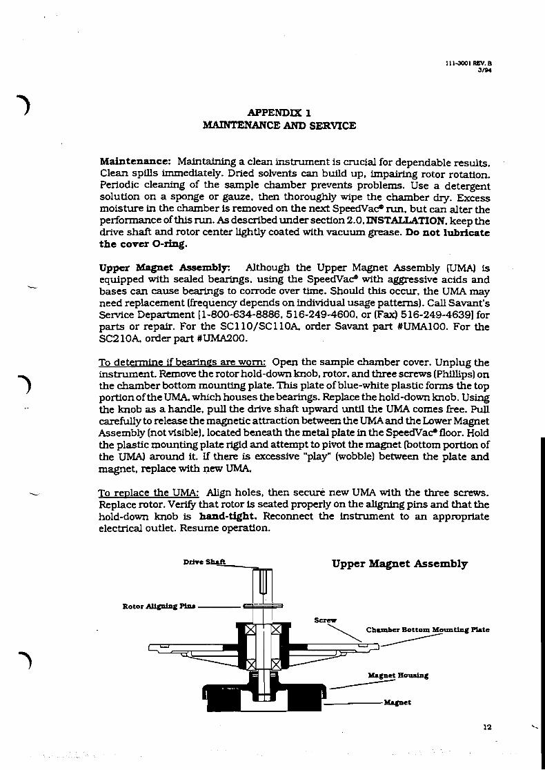
To determine if bearings are worn: Open the sample chamber cover. Unplug the instrument. Remove the rotor hold-down knob. rotor. and three screws (Phillips) on the chamber bottom mounting plate. This plate of blue-white plastic forms the top portion of the UMA. which houses the bearings. Replace the hold-down knob. Using the knob as a handle. pull the drive shaft upward until the UMA comes free. Pull carefully to release the magnetic attraction between the UMA and the Lower Magnet Assembly (not visible]. located beneath the metal plate in the SpeedVaC floor. Hold the plastic mounting plate rigid and attempt to pivot the magnet bottom portion of the UMAI around it. If there is excessive "play" (wobble) betwten the plate and magnet, replace with new UMA.
- To replace the UMA: Align holes, then secure new UMA with the three screws. Replace rotor. Verlfy that rotor is seated properly on the aligning pins and that the hold-down knob is hand-tight. Reconnect the instrument to an approprfate electrical outlet. Resume operation.
~ r h e shaft Upper Magnet Assembly
Rotor AUtphg Pip. I I I
Chamber Bottom

APPENDIX 2 APPLICATION INFORMATION
Dislocation due to braking: When highly discrete solutes are dried using ordinary rotors and the total rotor mass is small. some users note that the m u t e solute pellet is dislocated by the concentrator's braking action, impeding recovery. For these critical applications. Savant recommends the use of a heavier rbtor. such as the RH64- 11 or the HRH4 rotor head, which holds two or four swing-out buckets. The conical tip of the sample tube swings out horizontally as rotatton increases. This draws solute to the Up of the tube, minimizing pellet dislocation on braking.
Tppical results: The following data were gathered using Savant's SC 1 10 SpeedVac? concentrator. RVTlOO (-55°C) Refrigerated Vapor Trap. VPlOO (1 13 liter/min) vacuum pump. the RH20-12 rotor. and 20 glass tubes of 12 x 75 mm. each containing 2 ml of solvent. Time is shown as hours:minutes.
These approximate d r y q times are presented as a guide only. Results will differ depending on type of vacuum pump, temperature and capacity of vapor trap. integrity of seal between fittings and connections, degree of contamination, number of tubes per nzn. and other factors.
S O L m
WATER
MEIHANa
huther improvements iq ewporation rate: Rotors with aluminum tube carriers, such as the RH20-12. conduct more heat to the samples and enhance evaporation.
To speed evaporation further, use a Savant Radiant Cover:
SEIl3PlG OF DRYING RATE
For the SCllO/SCllOA. order the Savant RC 100 Radiant Cover. For the SC21OA. order the Savant RC200 Radiant Cover.
IDW
245
055
WARNING: Never shine a lamp or heat lamp through the standard acrylic chamber cover. The cover absorbs heat and will deform. especially while the sample chamber is under vacuum.
Recontiguration: The polypropylene vacuum fittings do not withstand strong lateral force. Should you ever need to remove avacuum line. carefully pull straight out to slide the tubing off the fitting. Reconflgure the SpeedVacO and system components as desired. To reattach the line. place a thin film of vacuum grease on the fitting: carefully slide new tubing straight on over fitting.
rklEmlM
3.97
a43
HIGH
2Q1
CEU
1115001 REV. B 3m4
APPENDIX 3 TIPS TO ENHANCE PERFORMANCE
1. 1 T3
Use glass tubes and vials In place of plastic.
Install and use a Radiant Cover on the Speedvat?.
heheat the Speedvat? chamber and rotor using MEDIUM DRYING RATE.
Use rotors with metal tube carriers instead of plastic rotors (e.g.. RH12-20. + RH8-18). These rotors conduct and transfer heat to tubes for faster
sample drying.
hewash plastic tubes with methanol to remove materials that inhibit or prevent evaporation of aqueous samples.
2. TO KEEP VACUUM PUMP OIL CLEAN, TRYTHE FOLLOWING:
Empty solvent(s) collected in the Refrigerated Vapor Trap as frequently as possible.
Change the oil in the vacuum pump when it becomes brown in color or smells of solvents being evaporated.
Attach a Savant VPOFlOO Vacuum Pump Oil Filter/Rtcirculator to your vacuum pump when evaporating acids (e.g.. HC1. acetic. TFAl in the SpeedVacm.
Attach a Savant SCT120 Chemical Trap with add neutralization cartridge when evaporatfng acids (i.e. HCl. acetic. TFA) in the Speedvat?.
If you are using a gel dryer with your Speedvat?. remove the gel dryer from the system. Use an oil-free/maintenance-he Savant Gel Pump" GP 1 10 for the gel dryer.
SAVANT SERVICE MANUAL __------------------- sCllO SpeedVac (R) Concentrators SCllOA and SC21OA SpeedVac Plus (R) Concentrators
CONTENTS ..................... Preface
1 THEORY OF OPERATION 1.1 The Application 1.2 Theory of Operation 1.3 Sequence of Operation 1.4 Overview of Maintenance
2 SERVICE PROCEDURES
Troubleshooting 2.1 Safety Precautions 2.2 Environmental Checks 2.3 Recommended Service Equipment 2.4 Troubleshooting Aids 2.5 Troubleshooting Sequence
Detailed Procedures 2.5a Disassembly and Replacement 2.6 Upper Mag~et Assembly 2.7 Lower Magnet Assembly 2.8 Vacuum Problems 2.9 Heater Assembly 2.10 All Other Problems
3 SPARE PARTS LIST 3.1 Specifications 3.2 Spare Parts Order Numbers
4 ENGINEERING DRAWINGS

Preface
This manual exp la ins how t o d e t e c t , diagnose, and c o r r e c t malfunct ions , t o t h e component l e v e l , i n t h e Savant SCllO SpeedVac (R) and t h e S C l l O A and S C 2 l O A SpeedVac P l u s ( R ) concen t r a to r s . I t is w r i t t e n f o r Savant manufacturing personnel and f o r Savant f i e l d s e r v i c e personnel. I t is a l s o a v a i l a b l e t o t r a i n e d customers who wish t o perform t h e i r own maintenance.
The manual is designed t o provide a step-by-step procedure f o r g e n e r a l i s t s t o e v a l u a t e a u n i t . La te r s e c t i o n s a l s o g ive more appl ied informat ion, such a s s o l u t i o n s t o s p e c i f i c problem r e p o r t s , and d e t a i l e d theo ry .
The manual does no t e x p l a i n how t o r e p a i r i n d i v i d u a l components, such a s c i r c u i t boards. F a i l e d c i r c u i t boards can be r e tu rned t o Savant, where t h e Service Department u ses customized testers t o determine whether t h e board can be r e p a i r e d and r e tu rned t o s e r v i c e . Other components should not be r e t u r n e d t o Savant.
~ r q a n i z a t i o n . A l l Savant s e r v i c e manuals are d iv ided i n t o t h e s e p a r t s :
o P a r t 1, Theorv of Operation, d e s c r i b e s t h e u n i t ' s purpose, p r i n c i p l e s of des ign , and sequence of ope ra t ion . P a r t 1 d e s c r i b e s t h e d i a g n o s t i c t o o l s t h a t a r e b u i l t i n t o t h e u n i t .
o P a r t 2 , Se rv i ce Procedures, shows how t o determine whether a u n i t has f a i l e d , how t o i d e n t i f y and r e p l a c e t h e f a u l t y component, and how t o perform o t h e r r equ i r ed maintenance procedures.
o P a r t 3 , Tables . p rovides s p e c i f i c a t i o n s f o r each model. These s p e c i f i c a t i o n s inc lude acceptab le measurements f o r each measurable parameter , and specifications and c h a r a c t e r i s t i c s of t h e component subsystems and f l u i d s . P a r t 3 a l s o l ists o r d e r numbers f o r s p a r e p a r t s f o r each model.
o Technical drawings appear a t t h e end of t h e manual.
Se rv ice notes, updat ing t h i s manual, w i l l be i s s u e d from t i m e t o t i m e by Savant. Se rv ice n o t e s w i l l reflect impor tan t changes i n procedures o r product ion. Each service no te w i l l r e p l a c e o r add s p e c i f i c pages t o t h i s manual. I n s e r t t h e s e pages i n t o the manual a s s p e c i f i e d . Discard any rep laced pages.
Each s e r v i c e no te w i l l have as its first page a change h i s t o r y , inc lud ing it and a l l p rev ious s e r v i c e no te s . Place t h e first page of t h e service n o t e j u s t a f t e r t h e cover page of t h i s manual, t o show t h a t t h e manual i nco rpora t e s t h a t and a l l previous s e r v i c e no te s .

PART 1 ------ THEORY O F OPERATION
1.1 The Applicat ion
The Savant SC11O/SC11OA/SC210A concentrators s p i n one of a v a r i e t y of r o t o r s . The r o t o r s contain sample t e s t tubes. Vacuum can be appl ied t o t h e sample chamber t o withdraw v a p o r s e a s t h e l i q u i d s evaporate. Ro ta t ion of t h e tubes prevents bumping and foaming a s vacuum is app l i ed . The u n i t s i s o l a t e t h e motor from t h e vacuum chamber. The u n i t s include a two-level e l e c t r i c hea te r . Applying h e a t t o t h e sample chamber encourages evaporation. I n a d d i t i o n , t h e samples cool a s some l i q u i d evaporates; applying h e a t coun te rac t s t h i s cool ing and can p ro tec t t h e samples from f reez ing .
A r u l e t h a t t h e I n s t r u c t i o n Manual emphasizes is t h a t vacuum should only be app l i ed t o t h e sample chamber when t h e r o t o r is spinning. I f t h i s r u l e is n o t followed, samples can bump, foam, and b o i l out of t h e t u b e . The SCllOA and SC2lOA SpeedVac Plus ( R ) concent ra tors have a n i n t e r n a l b leeder solenoid; the u n i t automatical ly c o n t r o l s t h i s solenoid t o comply with t h i s rule. The SCllO SpeedVac ( R ) concen t ra to r does not have such a solenoid; vacuum is a p p l i e d manually using a Savant b leeder valve.
The S C l l O A and SC2lOh models d i f f e r only i n s i z e . The SCllO and ScllOA hold sma l l e r r o t o r s , some of which hold .up t o 100 sample tubes . The SC2lOA holds l a r g e r r o t o r s and can accomodate up t o 200 tubes .
( A r e f r i g e r a t e d t r a p is always used with t h e apparatus t o p r o t e c t t h e vacuun pump, b u t t h i s is n o t important i n se rv ic ing t h e concent ra tor . )
1 . 2 Theory of Operat ion
The concentrators have two modes of operat ion:
o Manual mode. The ope ra to r a c t i v a t e s r o t a t i o n and chamber heat ing us ing t h e swi tches on t h e concen t ra to r ' s f r o n t panel. On t h e S C 1 1 0 , t h e opera tor opera tes a manual b l e e d e r valve a t t h e t o p of t h e concent ra tor , and m u s t sequence t h e app l i ca t ion of r o t a t i o n and vacuum,manually. On the SC11OA/SC21OA, an i n t e r n a l vacuum solenoid opera tes a u t o n a t i c a l l y .
o Slave mode (SCllOA/SC210A). The use r a t t a c h e s a Savant SclOZl c o n t r o l l e r t o t h e 9-pin connector a t t h e rear of t h e u n i t and connects t h e sample chamber vacuum l i n e t o the c o n t r o l l e r . The c o n t r o l l e r opera tes t h e r o t o r and g ives t h e

u s e r many op t ions f o r automatic o r timed ope ra t ion . However, t h e f ront-panel DRYING RATE switch s t i l l c o n t r o l s t h e c o n c e n t r a t o r ' s chamber hea t e r .
A c i r cu i t board i n s i d e t h e concent ra tor c o n t a i n s r e l a y s by which t h e u n i t r o t a t e s o r brakes t h e r o t o r ; c o n t r o l s t h e chamber h e a t e r ; and a c t i v a t e s t h e i n t e r n a l vacuum so leno id (SCllOA/SC21OA o n l y ) . LEDs monitor t h e s t a t e of each r e l a y . S C l l O s and S c l l o A s . conf igured f o r 220VAC, and a l l SC210As, have a cover lock, d r iven from t h e board without us ing a r e l ay ; t h i s l i n e is a l s o monitored by an LED.
A PAL i n t e g r a t e d c i r c u i t on t h e board ensures c o r r e c t opera t ion i n each of t h e ope ra t ing modes.
1 .3 Sequence o f ope ra t ion -
Each d e v i c e i n t h e c o n t r o l l e r can be cons idered sepa ra t e ly :
Rotor. The concen t r a to r can select r o t a t i o n o r braking. Ro ta t ion is enabled only i f a l l of t h e fo l lowing a r e t r u e : (1) t h e ROTOR swi tch on t h e f r o n t panel is ON; ( 2 ) t h e chamber cover is c l o s e d ; ( 3 ) any a t t ached S C 1 0 2 1 c o n t r o l l e r pe rmi t s r o t a t i o n . I n S l a v e mode, t h e u s e r l e a v e s t h e ROTOR swi tch ON and t h e S C 1 0 2 1 c o n t r o l s r o t o r r o t a t i o n . The f ront-panel ROTOR swi tch se rves a s an emergency s t o p . I n Manual mode, t h e f ron t -pane l ROTOR switch c o n t r o l s r o t a t i o n . On t h e SC11OA/SC210A1 swi tch ing t h e u n i t ON a l s o starts t h e sequence f o r evacuat ing t h e chamber (see below).
Switching the SCllO OFF immediately beg ins brak ing t h e r o t o r . Switching t h e SCllOA/SC21OA OFF r e l e a s e s vacuum, wa i t s f o r a f ac to ry - se t i n t e r v a l , and t h e n begins brak ing . I n both cases, t h e u n i t r e l e a s e s t h e brake when t h e r o t o r slows t o 6 RPM. Dynamic braking is achieved by applying DC v o l t a g e t o t h e AC motor.
\,
Chamber h e a t e r . I n both ope ra t ing modes, t h e DRYING RATE switch on t h e concen t r a to r f r o n t pane l c o n t r o l s t h e chamber h e a t e r . Switching it t o L O W d i s a b l e s t h e h e a t e r ; swi t ch ing it t o MED o r H I G H enables t h e h e a t e r . The MED and H I G H s e t t i n g s enable c i r c u i t s f ac to ry - se t a t 43'C.or 6 0 ' C , r e s p e c t i v e l y . The c i r c u i t board swi tches o f f t h e chamber h e a t e r when t h e chamber ach ieves t h e r e s p e c t i v e temperature.
When a r a d i a n t cover is a t t ached t o t h e SC11OA/SC21OA1 t h e effect of t h e HIGH s e t t i n g changes. I n t h e HIGH s e t t i n g , n e i t h e r t h e r a d i a n t cover no r t h e chamber h e a t e r w i l l o p e r a t e u n t i l t h e chamber r o t a t i o n reaches 1000 RPM.
Rota t ion sensor . A Ha l l - e f f ec t switch senses r o t a t i o n of t h e r o t o r . The SCllOA/SCZlOA provide an "up-to-speedu s i g n a l , based on t h i s switch, a t t h e 9-pin connector i n c a s e an SC1021 c o n t r o l l e r is connected. On S C l l O s and SCllOAs configured f o r

220VAC, and on a l l SC210As, t h e u n i t unlocks t h e cover only when t h i s s w i t c h d e t e c t s t h a t r o t o r speed is l e s s than 6 RPM. The ) cover is normally locked; it is locked when t h e power is o f f . Whether o r no t t h e r e i s a cover lock, a swi t ch senses whether t h e cover is c losed . This s i g n a l goes t o t h e 9-pin connector i n c a s e an SC1021 c o n t r o l l e r is connected.
Vacuum s o l e n o i d . The c o n t r o l l e r uses t h r e e of t h e 9-pin connectors t o ope ra t e t h e vacuum s o l e n o i d i n s i d e t h e SC11OA/Sc210A. The c o n t r o l l e r swi tches t h e so leno id t p vacuum only when r o t o r r o t a t i o n reaches 1000 RPM.
The c o n c e n t r a t o r does not include a vacuum gauge. The Sc1021 c o n t r o l l e r o r an e x t e r n a l vacuum gauge such as t h e Savant VG5 is used t o r ead vapor pressure i n t h e vacuum l i n e going t o t h e concen t ra to r chamber.
The concen t ra to r does not have any s p e c i a l power-on/power-off .- sequence.
1 . 4 Overview of Maintenance
Since the u n i t ' s behavior d i f f e r s depending on t h e a t tached equipment, it s i m p l i f i e s s e r v i c e t o fo l low t h e s e r u l e s : - -
o Always ask t h e customer which c o n c e n t r a t o r model is i n use; end i n t h e cese of t h e SCllOA/SCZlOA, whether an Sc1021 c o n t r o l l e r o r r a d i a n t cover is a t t a c h e d .
o Always de tach any such apparatus b e f o r e eva lua t ing f a i l e d u n i t s . I f t h e customer r e p o r t s a f a i l u r e i n Slave mode,- v e r i f y t h a t t h e u n i t works i n Manual mode, then determine whether t h e u n i t sends c o r r e c t s i g n a l s t o t h e connector.
PART 2 ------ SERVICE PROCEDURES
2.1 Safety precautions
The concentrator uses AC power, and some of the service procedures in this chapter require operation with the cover off, exposing power lines. This raises the risk of electrical shocks. The unit should only be plugged into a circuit protected by a Ground-Fault Interruptor (GFI). This minimizes injury from shock. In addition, you should not touch exposed wires at all without first unplugging the unit.
An additional hazard to the equipment is as follows: The circuit board and indicator panel contain electronics that can be damaged
--.- by static electricity (by giving it a shock). When removing a circuit board, always hold it by the sides. Persons doing extensive maintenance on circuit boards should be grounded, such as by wearing wrist straps. When shipping a circuit board, always enclose it in a static-protective bag.
2.2 Environmental Checks
The only required environmental check is that the unit be level. Vibration and poor performance can be caused by operating the unit on a tilted surface. If this is the case, correct the environment and then retest the unit.
2.3 Recommended Service Equipment
o Volt-ohm meter (VOM)
L o Variable-frequency strobe light o Blade and Phillips screwdriver
2.4 Troubleshooting Aids
There are five discrete LEDs-on the circuit board that are numbered. The function of these LEDs are as follows:
LED 1 Front-panel LED; always on if the DRYING RATE switch is HIGH. (If the radiant cover is installed, LED 1 is ON only when the chamber heater and the radiant cover are both activated. The LED is off whenever the rotor rotation is below 1000 RPM.)
LED 2 Front-panel LED; always on if the DRYING RATE switch is MEDIUM-
LED 3 Always on if the DRYING RATE switch is LOW LED 4 Front- ane el LED; always on if the ROTOR switch is ON -- -
LED 5 ~ l w a ~ s - o n if the ROTOR switch is OFF

) There a r e a l s o two banks of LED. t h a t provide addi t ional s t a t u s . They a r e labeled on t he c i r c u i t board.
The LEDs i n bank LEDSl have t h e following functions:
SLND On i f t h e chamber cover solenoid is actuated t o unlock t h e cover (220VAC un i t s only)
CVR On i f t h e chamber cover is closed S AV On i f r e lay 1 is actuated ( i f t h e un i t has switched t h e
i n t e r n a l SpeedVac Automatic Valve t o apply vacuum t o t h e concentrator chamber)
The LEDs i n bank LEDS2 have t h e following functions:
HTR On i f r e lay 2 is actuated ( i f t h e chamber heater i s on) RCO On i f r e lay 3 is actuated ( i f t h e rad ian t cover i s on)
.- BRX On i f re lay 4 is actuated ( i f t h e u n i t is braking the r o t o r )
MOTOR On i f re lay 5 is actuated ( i f t h e u n i t is ro t a t i ng t h e r o t o r )
2.5 Troubleshooting Sequence
The presence of optional attachments a f f e c t s t h e operation of t h e concentrator. Therefore, t o s implify troubleshooting, f i r s t renove any S C 1 0 2 1 con t ro l l e r connected t o t h e r e a r of t he concentrator. Also disconnect any r ad i an t cover from t h e r e a r of t h e concentrator . Plug t he u n i t i n t o an operat ing e l e c t r i c a l o u t l e t of t h e proper voltage.
Quickly check t h e c i r c u i t board's vol tage and log ic by opera t ing t he DRYING RATE switch. When the re is no con t ro l l e r o r rad ian t cover a t tached, and when the chamber i s a t approximately ambient - temperature, t h e LEDs by t he legends H I G H and MED should l i g h t up when you put t h e switch i n t h e respect ive posi t ion. In t h e LOW posi t ion , n e i t h e r LED should be lit.
o I f n e i t h e r LED is lit i n any switch pos i t ion , look f o r a power f a u l t . Verify t h a t t h e e l e c t r i c a l o u t l e t is opera t ing by plugging a lamp or o ther appliance i n t o it. Unplug the u n i t , remove t h e bottom p l a t e and inspec t t h e fuse (Fl, 0.5 amp, 250VAC) on t h e c i r c u i t board. I f it is blown, rep lace it and r e t e s t . I f the fuse is no t blown, plug t h e u n i t back i n and c a r e f u l l y ver i fy t h a t AC is present a t t h e power connector, J8 . I f so, r e tu rn t h e c i r c u i t board. If not , replace t h e power cord o r cable t o t h e c i r c u i t board.
o Other abnormal pat terns of LED l i g h t i n g mean t h a t you should r e tu rn t h e c i r c u i t board t o Savant.
Before checking t h e r o t o r operat ion, e n s u r e t h a t a r o t o r is in s t a l l ed i n t h e concentrator chamber, and t i g h t l y held i n p l ace

us ing t h e r o t o r hold-down knob. Close t h e c o v e r and swi tch t h e ROTOR swi t ch ON. L i s t e n f o r excess ive n o i s e . Allow 20 seconds f o r t h e SCllO/SCllOA t o come up t o speed; a l l o w 45 seconds f o r t h e SCZlOA t o come up t o speed. Use t h e var iab le - f requency s t r o b e l i g h t t o measure t he r o t a t i o n speed: Sh ine t h e l i g h t i n t o t h e r o t o r chamber and a d j u s t t h e knob u n t i l t h e r o t o r appears t o be s t a t i o n a r y , t h e n r e a d RPM o f f t h e knob.
If t h e u n i t is no isy when r o t a t i n g o r i f t h e r o t a t i n g speed is 2 0 % less than its r a t e d speed , then s e r v i c e t h e motor a s de sc r ibed i n t h e n e x t s e c t i o n s .
2.5a Disassembly and Replacement
Access t o t h e i n t e r i o r of t h e concen t ra to r r e q u i r e s t h a t t h e b l u e c a s i n g b e s epa ra t ed from t h e white cover. Most o f t h e i n t e r n a l
<- dev ices a r e f a s t ened t o t h e whi te cover. To s e p a r a t e the c a s i n g from t h e cover , f o l l o w t h e s e s t eps :
o U s e a P h i l l i p s s c r e w d r i v e r t o remove t h e f o u r screws from t h e base of t h e c o n c e n t r a t o r . (Do n o t remove t h e f o u r r eces sed screws.)
o A t t h e r e a r of t h e white cover, t h e r e a r e t w o b o l t s on the unders ide . They a r e v i s i b l e from t h e r e a r o f the u n i t . U s e a 1 / 4 " n u t driver t o remove t h e s e two n u t s .
o On t h e SCllOA/SC210A, t h e vacuum s o l e n o i d must be d i sconnec ted from the white cover, by removing both the vacuum t u b i n g and the e l e c t r i c a l connec to r . A l t e r n a t i v e l y , you can unscrew t h e f o u r recessed screws a t t h e base of t h e c o n c e n t r a t o r . t o d e t a c h t h e vacuum s o l e n o i d from t h e b l u e c a s i n g .
L o Take hold of t h e w h i t e cover and l i f t it s t r a i g h t up. T h i s
is necessary because t h e r e a r e two g u i d e p i n s beneath it.
To remove t h e chamber c o v e r , s l i d e ou t t h e h i n g e p i n s , u s ing p l i e r s o r wire c u t t e r s . U s e a wood b lock o r p e n c i l t o p rov ide l eve rage and avo id damaging t h e p a i n t f i n i s h .
2 .6 Upper Magnet Assembly
The Upper Magnet Assembly, a c c e s s i b l e from the sample chamber, c o n t a i n s bea r ings t h a t c a n wear ou t s i n c e t h e y a r e t y p i c a l l y opera ted i n a vacuum. The I n s t r u c t i o n Manual a d v i s e s t h e u s e r t o l i g h t l y apply vacuum g r e a s e t o t h e r o t o r s h a f t t o extend the l i f e of t h i s assembly. The Upper Magnet Assembly i s a p o s s i b l e sou rce of r e s i s t a n c e t o r o t a t i o n , and of no i se .
Open t h e chamber cove r . Remove t h e hold-down knob, r o t o r , and
t h r e e P h i l l i p s screws on t h e mounting p l a t e . Replace the hold- down knob. P u l l t h e s h a f t upward u n t i l t h e magnet comes f r e e . 3 You have removed t h e Upper Magnet Assembly. Hold t h e mzgnet r i g i d and r o t a t e t h e mounting p l a t e . I f t h e r o t a t i o n i s d i f f i c u l t o r uneven, rep lace t h e assembly with a spare Upper Magnet Assembly.
For t h e SCllO o r SCllOA, order Savant U M A 1 0 0 . For t h e SCZlOA, order Savant U M A 2 O O .
2 .7 Lower Magnet Assembly
I f manual r o t a t i o n of t h e Upper Magnet Assembly seems normal, do not r e i n s t a l l t h e Upper Magnet Assembly y e t . The assembled u n i t can f a i l even though f a i l u r e s a r e not ev ident i n t h e disassembled
.- pieces . This i s because, when assembled, t h e upper and lower magnets p u l l toward each o ther . A f a i l u r e o r misadjustment of t h e set screws on t h e Lower Magnet Assembly can impede r o t a t i o n only when t h e u n i t is assembled.
c lose t h e chamber cover and switch t h e ROTOR switch t o ON without t h e Upper Magnet Assembly i n s t a l l e d . I f t h e motor r o t a t e s , o r r o t a t e s q u i e t l y , when t h i s was not t h e case before, then unplug t h e u n i t , remove t h e bottom p l a t e and remove t h e four screws t h a t
7 secure t h e motor mountinq bracket . Adjust t h e two i 8 - 3 2 set I screws s o t h a t t h e drive-magnet is exac t ly 1/16" from t h e
s t a i n l e s s steel c losure p l a t e . ( T h i s p l a t e covers t h e hole t o t h e vacuum chamber. )
Whi le t h e u n i t is a p a r t , v e r i f y t h a t switching t h e ROTOR switch ON t u r n s t h e LED labeled MOTOR on and t h e one labe led BRLXE o f f . This v e r i f i e s t h a t t h e c i r c u i t board is t r y i n g t o r o t a t e t h e r o t o r and t h a t t h e brake is o f f . I f t h e s e LEDs l i g h t inappropr ia t e ly , r e t u r n t h e c i r c u i t board t o Savant, i n d i c a t i n g a
\L l o g i c e r r o r i n r o t o r r o t a t i o n o r braking, a s t h e case mcy be.
Reassemble t h e u n i t . I f t h e motor is slow o r noisy even vhen t h e Upper Magnet Assembly is removed, then rep lace t h e motor and Lower Magnet Assembly.
2.8 Vacuum Problems
I f t h e appara tus f a i l s t o achieve o r maintain vacuum and if t h e f a u l t is t r a c e d t o t h e concentrator , t h e r e a r e only four loca t ions where l e a k s o r obs t ruc t ions can occur. Inspect them, s t a r t i n g with t h e e a s i e s t t o reach:
7 o Cover. Open t h e cover and v i s u a l l y inspec t t h e O-ring f o r wear o r degradat ion. Replace it i f necessary. The cover O- r i n g should never be greased.

o Rear vacuum f i t t i n q . (This f i t t i n g is r a r e l y t h e source of t h e l e a k . ) I n s p e c t t h i s f i t t i n g and r ep lace it i f necessary.
o Vacuum solenoid (SCllOA/SCZlOA o n l y ) . To v e r i f y t h a t t h e i n t e r n a l vacuum so leno id is not obs t ruc t ing vacuum o r l eak ing , t ake it out of t h e c i r c u i t : Connect t h e vacuum l i n e s t h a t l e a d t o t h e vacuum solenoid t o each o t h e r us ing a two-ended tub ing connector . Then apply vacuum t o t h e concent ra tor and s e e i f adequate vacuum is reached. I f it i s , rep lace t h e so leno id .
o Bottom s e a l . Remove t h e motor a s descr ibed i n Sec t ion 2.7. Remove t h e s t a i n l e s s s t e e l c losure p l a t e , exposing t h e h o l e i n t h e sample chamber. Visua l ly in spec t t h e O-ring between t h e s e su r faces f o r wear o r degradation. Replace it i f necessary. L i g h t l y apply vacuum grease t o this O-ring.
2 . 9 Heater Assembly
The h e a t e r is i n t h e sample chamber cas t ing . Gain access t o it by disconnect ing power and removing t h e bottom p l a t e . The h e a t e r can burn ou t over t i m e . I n add i t ion , t h e h e a t e r is p ro tec t ed by a thermal fuse t h a t blows if t h e chamber t enpe ra tu re eve r reaches
\ 9 8 ' C . E i the r event can impede chamber heat ing. J
The h e a t e r needs replacement i f i ts r e s i s t a n c e is g r e a t e r than t h e va lue s p e c i f i e d i n Sec t ion 3 .1 .
T e s t t h e r e s i s t a n c e a c r o s s t h e thermal fuse . If t h e f u s e is blown ( i n f i n i t e r e s i s t a n c e ) , t h e n r ep lace it. Any t i m e you r ep lace a blown thermal f u s e , look f o r an underlying problem: T e s t t h e thermis tor and ensu re t h a t it is connected t o the c i r c u i t board. Res i s t ance a c r o s s t h e the rmis to r should b e about
L 10K ohms when t h e ambient temperature is 25'C. Replace t h e the rmis to r i f it appea r s t o b e bad. Repairing o r r e a t t a c h i n g t h e the rmis to r w i l l c o r r e c t a runaway reques t f o r h e a t and w i l l
' p revent blowing ano the r thermal fuse.
A f t e r any r e p a i r concerning chamber hea t ing , check t h e ope ra t ion of chamber hea t ing a f t e r you- r ep lace t h e Heater Assembly. Sv i t ch t h e ROTOR OFF, p l a c e a thermometer i n t h e chamber, and t es t t h e MED and HIGH switch p o s i t i o n s . The chamber temperature should s t a b i l i z e a t 4 3 ' C o r 60°C, r e spec t ive ly . I f dur ing this test the chamber ever exceeds 70*C, and you have t e s t e d t h e the rmis to r , r ep lace t h e c i r c u i t board. Return the o l d c i r c u i t board t o Savant, i nd ica t ing a l o g i c e r r o r i n chamber hea t ing .
2.10 A l l Other Problems
3 Problems with a s i n q l e device . Problems may occur w i t h :
o t h e cover lock (220VAC u n i t s only) o ope ra t ion of t h e i n t e r n a l vacuum solenoid
I n t h e s e cases , look a t t h e corresponding LED on t h e c i r c u i t board ( t h e one l abe led COVER f o r t h e cover lock , o r SAV f o r t h e vacuum so leno id ) t o v e r i f y t h a t t h e c i r c u i t board is t r y i n g t o ope ra te t h e device appropr i a t e ly . I f no t , r e p l a c e t h e ' c i r c u i t board. Return t h e o l d c i r c u i t board t o Savant i n d i c a t i n g a l o g i c f a i l u r e i n t h e opera t ion of t h a t device.
Analyzing t h e r e l a y c o n t a c t s o r c i r c u i t board connectors may revea l a bad r e l a y . Handle t h i s problem by r e p l a c i n g t h e c i r c u i t board. If t h e s i g n a l s are good a t t h e connectors , t hen r e p a i r o r r ep lace the a f f e c t e d device.
L
SC1021 ~ r o b l e m s . I f problems occur only when t h e SClO2l is a t tached , use t h e VOM o r osc i l lo scope t o analyze the s i g n a l s on t h e 9-pin connector t o ensure they a r e c o r r e c t .
P i n s e n a b l i n s remote c o n t r o l of t h e c o n c e n t r a t o r P in 1 Grounded by SC1021 c o n t r o l l e r i f it is resent -
Pin 2 GROUND r e f e r e n c e f o r p i n s 1-6, produced- by concent ra tor P i n 3 Grounded by SClO2l c o n t r o l l e r t o s t a r t a concen t ra to r
run; switched t o h igh impedance by c o n t r o l l e r t o s t a r t t h e braking sequence
P i n 4 Grounded by t h e concen t ra to r i f it is present P in 5 Grounded by t h e concen t ra to r when t h e cover is c losed P i n 6 Grounded by t h e concen t ra to r when t h e r o t o r reaches
67% of its maximum RPM
~ Pin 7 Return ( n e u t r a l )
L Pin 8 Switched AC power t o t h e so leno id P i n 9 GROUND
SECTION 3 ---------
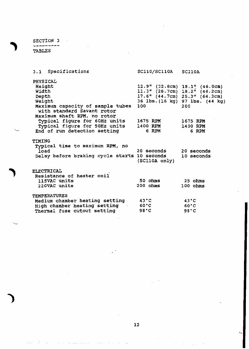
3.1 Spec i f i ca t ions SCllO/SCllOA SCZlOA
PHYSICAL Height Width Depth Weight Maximum capaci ty of sample t u b e s
with s tandard Savant r o t o r ~aximum s h a f t RPM, no r o t o r Typical f i g u r e f o r 60Hz u n i t s Typical f i g u r e f o r SOHz u n i t s
L End of run detec t ion se t t ing
12.9" (32.8cm) 18.1" ( 4 6 . O c m ) 11.3" (28.7cm) 18.2" (46.2cm) 17.6" (44.7cm) 25.3" (64.3cm) 36 l b s . (16 kg) 97 l b s . ( 4 4 kg) 100 200
1675 RPM 1675 RPM 1400 RPM 1400 RPM
6 RPM 6 RPM
T I M I N G Typical t i m e t o maximum RPM, no
load 20 seconds 20 seconds Delay before braking cyc le s t a r t s 10 seconds 10 seconds
(SC11OA only)
ELECTRICAL Resis tance of hea te r c o i i
115VAC u n i t s 50 ohms 25 ohms 220VAC u n i t s 200 ohms 100 ohms
TEMPERATURES Medium chamber hea t ing s e t t i n g 43'C High chamber hea t ing se t t ing 60'C Thermal fuse cutout s e t t i n g 98'C
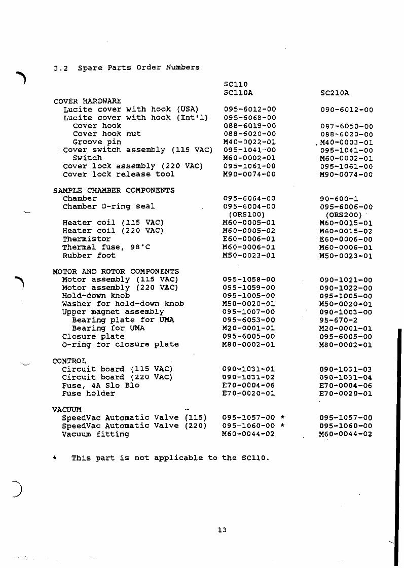
3.2 Spare P a r t s Order Numbers
7 COVER HARDWARE
Luc i t e cover wi th hook (USA) Luci te cover wi th hook ( I n t ' l )
cover hook Cover hook n u t Groove p in
Cover switch assembly (115 VAc) Switch
Cover lock assembly (220 VAC) Cover lock release t o o l
CHAMBER COMPONENTS Chamber Chamber O-ring s e a l
L
Heater c o i l (115 VAC) Heater c o i l (220 VAC) Thermistor Thermal fuse , 98'C Rubber foo t
MOTOR AND ROTOR COMPONENTS Motor assembly (115 VAC) Motor assembly (220 VAC) Hold-down knob Washer f o r hold-down knob Upper magnet assembly
Bearing p l a t e f o r UMA Bearing f o r UMA
Closure p l a t e O-ring f o r c l o s u r e p l a t e
L. CONTROL ci rcui t board (115 VAC) 090-1031-01 C i r c u i t board (220 VAC) 090-1031-02 Fuse, 4 A S l o B l o E70-0004-06 Fuse holder E70-0020-01
VACUUM .- SpeedVac Automatic Valve (115) 095-1057-00 * SpeedVac Automatic Valve (220) 095-1060-00 * Vacuum f i t t i n g M60-0044-02
* This p a r t is no t a p p l i c a b l e t o t h e SC110.