instruction manual - Gusher Pumps · 7600 H instruction manual and 7650 H SERIES GUSHER ... report...
19
instruction manual instruction manual 7600 H and 7650 H SERIES GUSHER PUMPS, INC. 115 INDUSTRIAL DRIVE WILLIAMSTOWN, KY 41097 PHONE: 859-824-3100 FAX: 859-824-7428 www.gusher.com MAINTENANCE • INSTALLATION • OPERATIONS
Transcript of instruction manual - Gusher Pumps · 7600 H instruction manual and 7650 H SERIES GUSHER ... report...

inst
ruct
ion
man
ual
inst
ruct
ion
man
ual
7600 Hand
7650 H SERIES
GUSHER PUMPS, INC.115 INDUSTRIAL DRIVEWILLIAMSTOWN, KY 41097PHONE: 859-824-3100FAX: 859-824-7428www.gusher.com
MAINTENANCE • INSTALLATION • OPERATIONS

TABLE OF CONTENTS
Warranty ............................................................................................................................................................................. 3
Receiving and Inspection ................................................................................................................................................... 4
Installation ........................................................................................................................................................................... 4
A. Pump Location ......................................................................................................................................................... 4
B. Foundation ............................................................................................................................................................... 4
C. Coupling Alignment.................................................................................................................................................. 5
D. Grouting ................................................................................................................................................................... 5
E. Pipe .......................................................................................................................................................................... 6
Operation ............................................................................................................................................................................. 6
A. Priming ..................................................................................................................................................................... 6
B. Initial Starting ............................................................................................................................................................ 7
C. Packed Pumps ........................................................................................................................................................ 7
D. Pumps With Mechanical Seals ................................................................................................................................. 7
Maintenance ........................................................................................................................................................................ 7
A. Lubrication ................................................................................................................................................................ 7
B. Coupling Alignment .................................................................................................................................................. 7
C. Packed Pumps ......................................................................................................................................................... 7
D. Pumps With Mechanical Seals ................................................................................................................................. 8
E. Impeller Adjustment .................................................................................................................................................. 9
Recommended Spare Parts ............................................................................................................................................... 9
Ball Bearing Installation .................................................................................................................................................... 10
Trouble Shooting .............................................................................................................................................................. 11
Disassembly ...................................................................................................................................................................... 12
Part Description Chart ....................................................................................................................................................... 13
Cross Sectional Drawings ............................................................................................................................................14-18
Maintenance History ......................................................................................................................................................... 19
Engineering Data .............................................................................................................................................................. 19
WARRANTY Gusher Pumps, Inc. will replace or repair, within one year of shipment from our plant, any pump in our judgement that has failed due to defects in materials or workmanship, provided the pump has been properly installed and maintained and has not been subject to abuse. These pumps must return to Gusher Pumps, Inc. with complete history of service for inspection and warranty consideration. Gusher Pumps, Inc. does not accept the responsibility for transportation to and from our plant. Furthermore, we do not assume any responsibility for consequential damage or loss of production.
3

RECEIVING and INSPECTION Gusher Pumps, Inc. has taken great care in preparing your pump for shipment, however, due to circumstances beyond our control, your shipment may be received dam-aged. Therefore, we strongly recommend that you take a few minutes to inspect your pump upon receipt. Check for cracked, bent, severely misaligned (minor misalign-ments most always occur during shipment) or even miss-ing parts. If any such damage has occurred, you must report it to the delivering carrier and Gusher Pumps, Inc. immediately.
We also recommend you check the model number, horse power, current characteristics, g.p.m. and ft. head of pump received to assure that you have received the pump you ordered for your specific operating conditions. If you should find some discrepancy, report it to Gusher at once.
INSTALLATION
When preparing your pump for installation, the discharge and suction ports must be clean and free of anything that might prohibit a tight connection. This is especially important on the suction-air leaks can cause a pump to operate poorly or to loose prime completely. If your pump has just been taken out of storage all the grease or preservative must be removed from ball bear-ing housing and thoroughly cleaned with kerosene or carbon tetrachloride and relubricated. On packed pumps it will be necessary to clean shaft sleeve and stuffing box with kerosene or carbon tetrachloride and repack. LOCATION - Whenever possible locate pump far enough below the minimum liquid level in the reservoir so there will be a positive head on the suction at all times. Where this is not possible, the pump should be located as near the source of supply as possible. Allow ample room for inspection and maintenance.
If your pump is not going to be installed within six months, several precautions must be taken;
1. Preservative treatment of bearings and machined surfaces is required.
2. Remove packing on pumps with packed stuffing box, the stuffing box and shaft sleeve must be oil lubricated to also protect against moisture.
3. Units equipped with mechanical seals must also be oil lubricated with an oil can through the NPT port while rotating the shaft by hand.
4. Pump suction and discharge ports must be covered to prevent foreign material getting into the pump and causing damage when pump is started at a later date.
5. Pump must be stored in a dry location. 6. Rotate pump shaft several times every other month.
FOUNDATION - The foundation should be of heavy con-struction to reduce vibration and must be rigid enough to resist the torque it may be subjected to. The founda-tion should be 2” to 6” larger than the base depending upon the size of the base. For style ‘CBM’ a space of approximately 2” should be left between the foundation and bottom of base for grouting. Use a pipe sleeved bolt (Fig. 1) to within 1/2” of the base for a foundation bolt. DO NOT grout until pipe connections and alignment has been established. To mount Gusher’s style ‘C’ (pedestal mount) the mount-ing holes for both driver and pump must be located, drilled and tapped in the field. As in Gusher’s style ‘C’ mounting, when mounting style ‘CC’ (close coupled) the mounting holes must be located, drilled and tapped in the field. It should be noted at this time that SPECIAL CARE must be taken when locating your pump for alignment, it is of utmost importance. Once the pump is set, the only means of adjusting is by shimming.
Fig. 1
4

5
When mounting Gusher’s style ‘CBM’ (base mounted) the complete unit is lowered into position, being sure the lifting straps are NOT attached to pump or motor, while align-ing foundation bolts with mounting holes in base. Locate leveling wedges as close to foundation bolts as possible (Fig. 2), adjust unit to desired position, plumb and level pump suction and discharge with leveling wedges, snug foundation bolts down hand tight - DO NOT TIGHTEN at this point.
COUPLING ALIGNMENT - Must be checked before and after start-up. Check parallel alignment by placing a straight edge across the two coupling flanges and mea-sure the offset at various points around the periphery of the coupling. DO NOT rotate the coupling. If offset ex-ceeds .010” re-align the coupling. See Fig. 3.
Check angular alignment with micrometer or caliper. Measure from the outside of the one flange to the outside of the other flange at intervals around the periphery of the coupling, DO NOT rotate the coupling. The difference between the maximum and minimum must not exceed .010”. If a correction is necessary, be sure to recheck par-allel alignment. See Fig. 4. GROUTING Build a form around the base as illustrated in Fig. 5. Pour grout into form being sure it flows under the base. Fill to within 3/4” to 1” of bottom of base. Allow to set 48 hours, recheck coupling alignment, make any adjustment that may be necessary and tighten founda-tion bolts securely.
Fig. 2
Fig. 3
Fig. 4 Fig. 5
Note:Wedge should be 2” taper per ft.

6
PIPE - can now be installed being sure to support the pipe independent of the pump. Never use pipe smaller than pump discharge and suction sizes, and preferably larger especially on the suction (one or two sizes larger). The suction line should be laid horizontally or with a gradual slope upward toward the pump. There should not be any high spots where air can collect and cause pump to lose prime. Use eccentric reducers from larger suction pipe to pump inlet to prevent formation of air pockets in the pipe (Fig. 6). Run pipe as direct as possible with a minimum
OPERATION Wire motor according to motor manufacturer’s specifica-tions and according to state and local regulations. Discon-nect motor/pump shaft coupling to prevent dry operation of the pump when checking direction of rotation. Operat-ing pump dry will cause damage to mechanical seal and may cause rotating parts to seize. To check direction of rotation jog motor starter, pump must rotate clockwise when viewing from the driving end looking over the mo-tor. Direction arrows are cast in impeller housings. TO CHECK ROTATION UPON START-UP COU-PLING SHOULD BE DISCONNECTED. JOG MOTOR TO CHECK ROTATION. FAILURE TO FOLLOW THIS PROCEDURE COULD RESULT IN DAMAGE TO THE PUMP.
of elbows and fitting. Never place a pipe line elbow in the horizontal plane directly at the pump suction (Fig. 7). Between the elbow and the pump suction use a straight pipe four to six pipe diameters long. Suction pipe reduc-ers should be connected directly to the pump suction whenever possible. Discharge pipe increasers should be connected directly to the pump discharge whenever pos-sible. Whenever possible avoid dynamic suction lifts of more than 15’. Suction line must be tight for proper oper-ation of the pump. Install a gate valve in discharge line as close to the pump as possible, see Fig. 6. If a foot valve is not used in the suction line, it is good practice to bell out suction pipe to lower the entrance velocities at the inlet (Fig. 8). Whenever possible the end of the suction should be a minimum of 3’ below the low liquid level (Fig. 8). The liquid near the pump suction should be free from agitation to prevent air entering the suction line. Liquid coming back into the reservoir should not enter the reser-voir near the pump suction pipe and the liquid should not drop from a high level (Fig. 8). NEVER throttle the pump on the suction side, always control flow by throttling on the discharge side of the pump.
Fig. 6
Fig. 8
When using a strainer on the suction install it as close to the pump as possible and select a strainer with a net area of at least four times that of the suction pipe. It must be inspected and cleaned regularly. NEVER force piping into position by pulling it in place with the pump suction and discharge flange bolts.Fig. 7
PRIMING No centrifugal pump will operate satisfactorily until it has been properly primed. Do not attempt to prime pump when operating and DO NOT under any circumstances operate the pump without being completely primed. Some of the most common methods of priming are flooded suction, foot valve in suction line, ejector (steam, water or air operated) and vacuum pump. With flooded suction, remove the air vent in top of pump casing to release entrained air.With foot valve the pump and suction pipe must be filled with the liquid being pumped. It is recommended to fill the discharge pipe several feet above the pump dis-charge, leave vent open while filling pipe and pump. The pump will remain primed unless the foot valve leaks or if the liquid is contaminated and does not allow foot valve to close tight.

7
When an ejector is used for priming it must be mounted at the highest point in the impeller housing to ensure re-moval of all the air in the casing and suction pipe. Oper-ate the ejector with the gate valve in the discharge line closed. Operate until ejector discharges a full steady flow of liquid. On pumps using packing it may be neces-sary to tighten packing gland (#9) to prevent pulling of air through shaft clearances. After pump is primed properly loosen gland to achieve a slight trickle of water through the stuffing box. The vacuum pump must be mounted at the highest point in the impeller housing to ensure complete removal of entrained air. Gate valve in discharge line must be closed. After pump is primed valves between vacuum pump and Gusher pump must be closed. On pumps using packing it may be necessary to tighten packing gland (#9) to pre-vent pulling of air through shaft clearances. After pump is primed properly loosen gland to achieve a slight trickle of water through the stuffing box.
INITIAL STARTING For initial starting of the pump, the gate valve in the dis-charge line should be closed and gradually opened as the motor reaches full speed (approximately 5 to 10 sec-onds). After pump has been in operation and the suction and discharge lines are filled with liquid, it is not neces-sary to close the gate valve when starting.
PACKED PUMPS At initial start-up loosen packing gland screws to allow free leakage. Then tighten screws uniformly on packing gland (#9) until leakage is reduced to approximately 30 drops per minute. Never tighten packing enough to stop all leakage, a slight leakage is required to lubricate pack-ing (#28) and prevent scoring of shaft sleeve (#20). Gusher uses non-asbestos packing which is a good general pur-pose packing, good for hot or cold water, brine, oils, mild caustics, solvents, acids and many general chemicals. It is suitable for medium to high pressure applications.
PUMPS WITH MECHANICAL SEALS In applications where leakage from the stuffing box is not permissible or is undesirable, Gusher pumps are avail-able in a wide variety of mechanical seals to meet most any application. Gusher uses a John Crane Type 21 seal as standard.
MAINTENANCE
1. Lubrication - All pumps are lubricated at the Gusher Plant and should not require additional lubrication for approximately 1200 hours of operation. A well planned maintenance schedule can only be devised after the first
six months of operation and the lubrication record re-view at that time. Each pump installation is unique and requires individual attention to set up the proper lubrica-tion schedule for each specific installation. About once a year it is recommended that the bearings be cleaned and flushed with kerosene or carbon tetrachloride and then relubricated.
NOTE: Grease lubrication is available on 51H & 52H Power Frames only. Oil bath lubrication is avail-able on 7071S, 7071M and 7071L as a stan-dard and as an option on 51H and 52H Power Frames.
2. Coupling Alignment - Must be checked before and after system start-up, after 300 hours of operation, and again after 1200 hours of operation. Follow procedure given in installation instruction. Again we strongly rec-ommend setting-up and following a routine preventative maintenance program to assure optimum life from your pump.
3. Packed Stuffing Box - DO NOT STOP LEAKAGE! Packed glands drawn up too tight increases power con sumption, increases wear on shaft sleeve and shortens life of packing. When leakage can no longer be controlled by drawing up on the packing gland (#9) add another ring of packing (#28) to the stuffing box. After further opera-tion and leakage again can no longer be controlled re-place the packing by using the following procedure:
1. Remove all old packing from the stuffing box. Clean box and shaft sleeve (20) thoroughly and examine for wear. Replace shaft sleeve if wear is excessive. Check bearing by lifting shaft up and down; do not expect packing to act as a bearing.
2. Use the right cross-section of packing, Gusher uses Non-Asbestos packing as our standard for gen-eral purpose applications. Packing for special appli-cations available, consult factory.
3. When using coil or spiral packing always cut the packing into separate rings. Never wind a coil of packing into a stuffing box. Rings can be cut either with butt (square) joint or diagonal joints.
The best way to cut packing rings is to cut them on a mandrel the same diameter as the shaft sleeve. Hold the coil packing tightly and firmly on the mandrel but do not stretch excessively. Cut the ring and try it in the stuffing box to make certain it fills the packing space properly with no gap in the joint at the O.D. of the ring.

8
It is necessary that the rings be cut to the correct size, otherwise service life is reduced.
4. Install one ring at a time. Make sure it is clean and has not picked up any dirt in handling. If clean oil is available, lubricate the shaft and the inside of the stuffing box.
Seat rings firmly. (Except for TFE filament and graph-ite yarn packings which should be snugged up very gently. Then wrench in gradually...after the pump is back in operation.) Joints of successive rings should be staggered and kept at 90O apart. Each individu-al ring should be firmly seated with a tamping tool. When enough rings have been individually seated so the nose of the gland (#9) will reach them, individual tamping should be supplemented by the gland. Nev-er depend entirely on the gland to seat a set of rings properly - this practice will jam the last rings installed but leave the bottom rings loose in the box.
5. After the last ring is installed take up bolts finger tight or very slightly snugged up. Do not jam the packing into place by excessive gland loading. Start pump, and take up bolts until leakage is decreased to minimum. Make sure gland bolts are taken up evenly, stopping leakage entirely at this point will cause the packing to burn up.
6. Allow packing to leak freely when starting up a newly packed pump. Excessive leakage during the first hour of operation will result in a better packing job over a longer period of time. Final adjustment should allow approximately 30 drops per minute to leak from the packing.
7. When specified, Gusher can provide means of lu-bricating the shaft and packing through a lantern ring by supplying water, oil, grease, or liquid handled in the pump.
8. If the stuffing box has a lantern ring, make sure the lantern ring, as installed, is slightly behind the fluid inlet so it will move under the inlet as gland pressure is ap-plied. (See illustration below.)
9. Replace packing when leakage cannot be con-trolled by further takeup on the gland.
Some of the most common reasons for packing failure are:
1. Improper installation
2. Uneven gland adjustment
3. Shaft misalignment and shaft whip
4. Improper selection of packing for liquid
5. Improper selection for pressure and temperature
6. Contaminated liquid (dirt, abrasives, etc.)
MECHANICAL SEAL The most important factor in mechanical seal, other than the sealing qualities, is the fact that once it has been prop-erly installed there is little or no maintenance required.
Some of the most common reasons for seal failure are:1. Improper installation2. Shaft misalignment and shaft whip
3. Wrong selection for liquid pumped4. Wrong selection for pressure and temperature5. Dirt or grit between faces6. Seal gland (#9) tightened unevenly so stationary seat
is not perpendicular to shaft.7. Operation without fluid
9
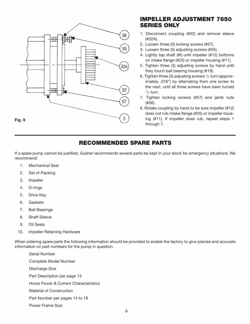
IMPELLER ADJUSTMENT 7650 SERIES ONLY
1. Disconnect coupling (#32) and remove sleeve (#32A).
2. Loosen three (3) locking screws (#57). 3. Loosen three (3) adjusting screws (#55). 4. Lightly tap shaft (#I) until impeller (#12) bottoms
on intake flange (#25) or impeller housing (#11). 5. Tighten three (3) adjusting screws by hand until
they touch ball bearing housing (#19). 6. Tighten three (3) adjusting screws 1/4 turn (approx-
imately .016”) by alternating from one screw to the next, until all three screws have been turned 1/4 turn.
7. Tighten locking screws (#57) and jamb nuts (#56).
8. Rotate coupling by hand to be sure impeller (#12) does not rub intake flange (#25) or impeller hous-ing (#11). If impeller does rub, repeat steps 1 through 7.
Fig. 9
RECOMMENDED SPARE PARTS
If a spare pump cannot be justified, Gusher recommends several parts be kept in your stock for emergency situations. We recommend:
1. Mechanical Seal
2. Set of Packing
3. Impeller
4. O-rings
5. Drive Key
6. Gaskets
7. Ball Bearings
8. Shaft Sleeve
9. Oil Seals
10. Impeller Retaining Hardware
When ordering spare parts the following information should be provided to enable the factory to give precise and accurate information on part numbers for the pump in question.
Serial Number
Complete Model Number
Discharge Size
Part Description per page 13
Horse Power & Current Characteristics
Material of Construction
Part Number per pages 14 to 18
Power Frame Size

10
Fig. 10
Fig. 11
Fig. 12
BEARING INSTALLATION Begin by cleaning your work area thoroughly, contami nants can cause bearing failures as fast as any other rea-son.
When a bearing is installed, the mounting force should be applied against the ring, and only the ring, which is being press-fitted. A bearing should never be forced onto a shaft by pressure or hammer blows applied to the outer ring, nor should the bearing be press-fitted into a housing by force applied to the inner ring. Using an arbor press, the bearing may be laid on a face block which contacts only the bearing inner ring and which has a hole diameter greater than the bearing bore, as shown in Fig. 10. The shaft is pressed through the bearing until it is seated firmly against the shaft shoul-der.
If the shaft is not too long, it can be supported beneath the table of the arbor press and the bearing pressed onto
it by ram pressure against a piece of soft metal tubing, as shown in Fig. 11. The tubing must be clean, inside and out, and the inside diameter of the tubing should be slightly greater than the bearing bore. The ends of the tubing should be square (with corners chamfered to avoid flaking) and should contact only the bearing inner ring. The shaft must be held in line with the ram of the arbor press to avoid cocking the bearing on the shaft seat.
When an arbor press is not available, the bearing can be driven onto the shaft seat by light hammer blows against the end of the soft metal tubing. These blows should be made alternately against opposite sides of the tubing face, and great care must be taken to avoid cocking the bearing as it is driven onto the shaft seat. When a ball bearing is installed onto the housing it is normally a slip fit, however if force is necessary to install bearing the force should be exerted on the outer ring of the bearing as shown in Fig. 12. Again the force must be applied evenly so as not to cock the bearing in the bore.
11
TROUBLE SHOOTING
NO WATER DELIVERED. (1) Pump not primed. + (2) Speed to low. (3) Discharge head too high. (4) Suction line or suction strainer is clogged. (5) Impeller completely clogged. (6) Wrong direction of rotation. (7) Too much clearance between impeller and intake flange.
NOT ENOUGH WATER DELIVERED. (1) Air leaks in suction or stuffing boxes. + (2) Speed too low. (3) Discharge head higher than anticipated. (4) Too much clearance between impeller and intake flange. (5) Impeller partially clogged. (6) Not enough suction head for hot water. (7) Mechanical defects: Wear ring is worn. Impeller damaged. (8) Impeller diameter too small. (9) Foot valve too small. (10) Foot valve or suction opening not submerged deep enough.
NOT ENOUGH PRESSURE. + (1) Speed too low. (2) Air in water. (3) Mechanical defects: Wear ring is worn. Impeller damaged. (4) Impeller diameter too small.
VIBRATION. (1) Bent shaft. (2) Pipe strain. (3) Impeller clogged. (4) Coupling alignment off.
PUMP WORKS FOR A WHILE AND THEN LOSES SUCTION. (1) Leaky suction line. (2) Water seal plugged. (3) Impeller clogged. (4) Air or gasses in liquid.
PUMP TAKES TOO MUCH POWER. + (1) Speed too high. (2) Head lower than rating, pumps too much water. (3) Specific gravity or viscosity too high. (4) Mechanical defects: Shaft bent. Power frame in bind. Wear ring is worn. (5) Impeller diameter too large. (6) Pump delivering too many gallons.
+ When directly connected to electric motors, check for full voltage across all electrical leads.

Disassembly Due to the wide variety of options available and custom specials that are manufactured, the instructions con-tained in this manual are to be used as a general guide-line only. If the pump in question deviates from these pro-cedures, please consult the factory.
ROTATING ELEMENT REMOVAL 1. Shut off main power switch to driver. 2. Lock out driver power to prevent accidental start-
up. 3. Close suction and discharge valves. 4. Drain impeller housing 5. Remove coupling guard. 6. Remove coupling sleeve (#32A). 7. Remove cap screws that secure stem plate (#18)
to impeller housing (#11). For ANSI CenterLline type models remove cap screws that secure stem (#7) to impeller housing (#11).
8. Unbolt bearing housing (#19) from base. For 7650 series unbolt pedestal (#41) from base.
9. On oil bath applications drain oil from bearing housing (#19).
10. Remove oil sight gauge from bearing housing (#19).
11. Remove rotating assembly from impeller housing (#11). In many cases it is advisable to have a spare pump to install to keep downtime to a minimum.
ROTATING ELEMENT 1. Remove impeller (#12). The impeller is secured to
the shaft (#1)by: A. Retaining screw (#35), retaining washer (#36),
drive key (#33).B. Lock nut (#26) drive key (#33).C. Impeller directly threaded to shaft. To remove
impeller, immobilize shaft and turn impeller counter clockwise.
2. Unbolt stem plate (#18) from stem (#7). Unbolt stem plate (#18) from seal/packing gland (#9). Remove stem plate. On packed pumps the pack-ing (#28) and shaft sleeve (#20). Usually will come off with the stem plate.
3. Remove shaft sleeve (#20) from shaft (#1). Me-chanical seal (#23) will come off with shaft sleeve (#20). Remove seal (#23) from sleeve (#20).
4. Remove packing (#28) and shaft sleeve (#20) from either shaft (#1) or stem plate (#18).
5. Remove seal/packing gland (#9) from shaft (#1).6. Unbolt and remove stem (#7) from bearing hous-
ing (#19).
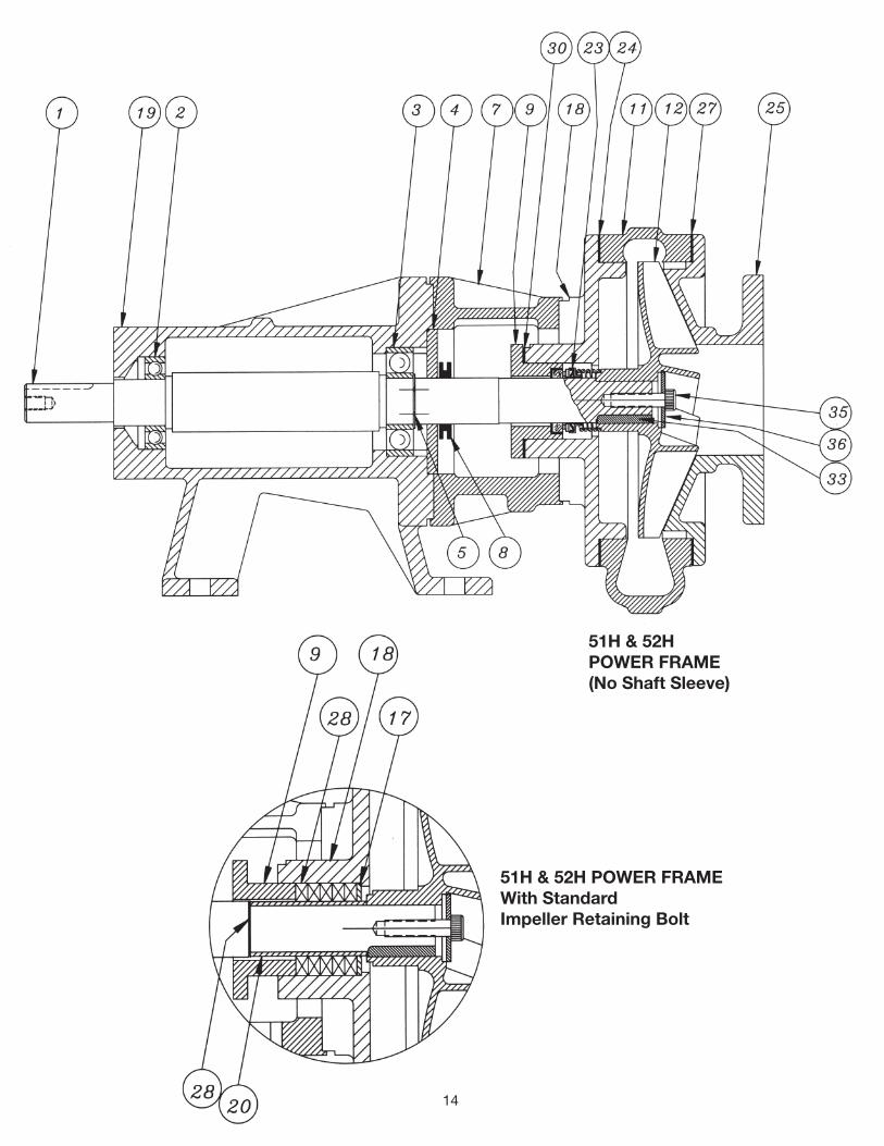
POWER FRAME A. 51H & 52H (7600 H Series).
1. Remove slinger (#8) from shaft (#1). 2. Unbolt and remove bearing retainer (#4) from
bearing housing (#19).
3. Slide Shaft Assembly out of bearing housing (#19).
4. Remove snap ring (#5) from shaft (#1).5. Remove ball bearings (#3) and (#2) from shaft(#1).
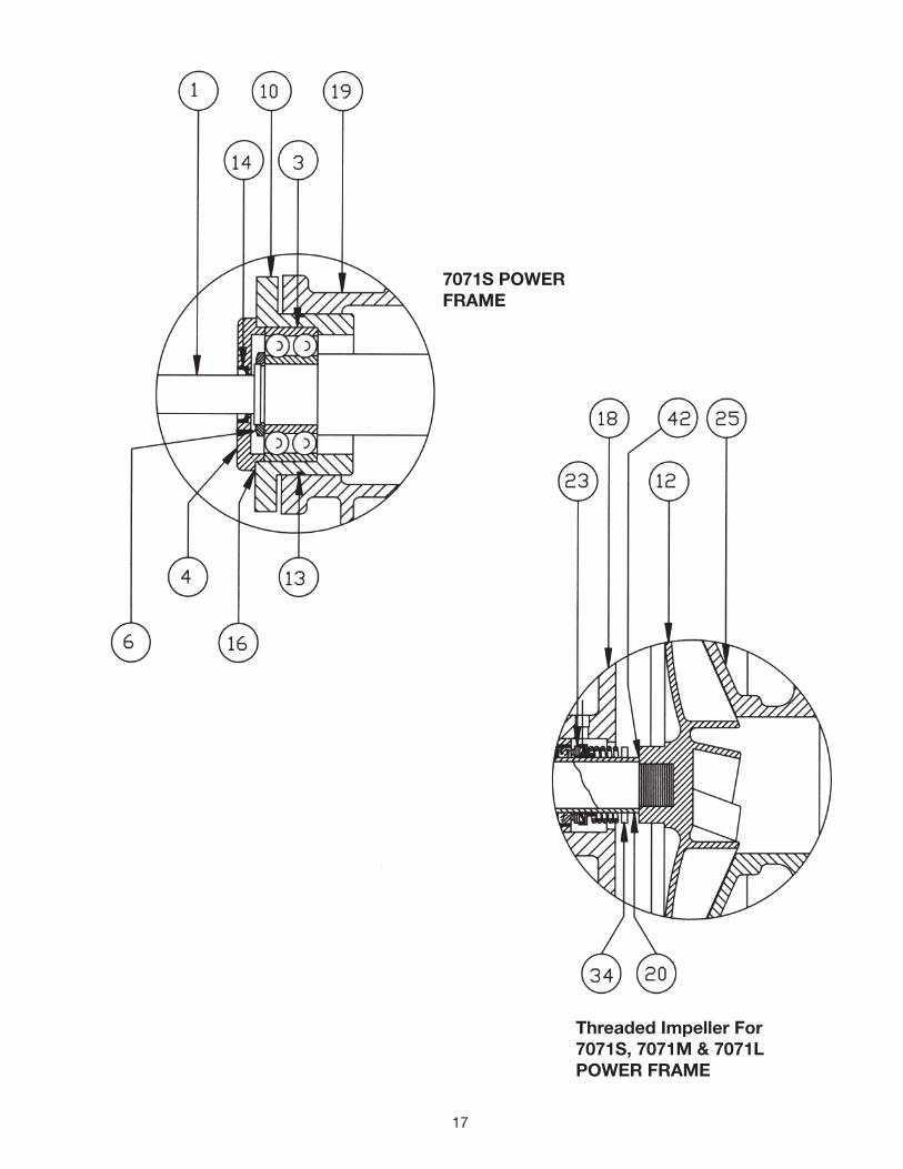
When installing new bearings refer to page 9. B. 7071S, 7071M and 7071L (7600 Series).
1. Remove slinger (#8) from shaft (#1). 2. Remove adjusting screws (#55), jamb nuts (#56),
and locking screws (#57) from cartridge (#10).3. Remove shaft (#1) and cartridge assembly from
bearing housing (#19).4. 7071S and 7071M
Remove oil seal (#22) from bearing housing. 7071L
Remove bearing retainer (#38) from bearing housing (#19). Remove oil seal (#22) from bear-ing retainer (#38).
5. Unbolt and remove bearing retainer (#4) from cartridge (#10).
6. Remove oil seal (#14) from bearing retainer (#4).7. Remove snap ring (#5) or lock nut (#6) from shaft
(#1).8. Slide cartridge (#10) off of ball bearing (#3).9. Remove bearings (#3) and (#2) from shaft (#1).
When installing new bearings refer to page 10. 10. Remove cartridge (#10) from shaft (#1).11. Remove O-ring (#13) from cartridge (#9).
12

13
PART DESCRIPTION CHART
When ordering parts use part description chart in conjunction with cross section drawings on pages 14 to 18. The following information should be provided to enable the factory to give precise and accurate information on part numbers for the pump in question.
A. Serial Number
B. Complete Model Number
C. Discharge Size
D. Part Description per page 13
E. Horsepower & Current Characteristics
F. Material of Construction
G. Part Number per pages 14 to 18
H. Power Frame Size
Shaft
Radial Ball Bearing
Thrust Ball Bearing
Thrust Bearing Retainer
Snap Ring
Lock Nut
Stem
Slinger
Packing/Seal Gland
Cartridge
Impeller Housing
Impeller
Cartridge O-ring
Oil Seal
Shaft Sleeve Gasket
Bearing Retainer Gasket
Packing Seat Washer
Stem Plate
Ball Bearing Housing
Shaft Sleeve
Oil Breather
Oil Seal
Mechanical Seal
Steam Plate Gasket
Intake Flange
Impeller Lock Nut
Intake Flange Gasket
Packing
Pedestal
Seal Gland Gasket
Impeller Housing Bracket
Coupling (see page 9)
Coupling Sleeve (see page 9)
Drive Key
Mechanical Seal Retainer
Impeller Retaining Screw
Impeller Retaining Washer
Radial Bearing Retainer
Radial Bearing Retainer Gasket
Gasket
Shaft Sleeve Drive Pin
Pedestal
Impeller O-ring
Adjusting Screws (see page 9)
Jamb Nuts (see page 9)
Locking Screws (see page 9)
1
2
3
4
5
6
7
8
9
10
11
12
13
14
15
16
17
18
19
20
21
22
23
24
25
26
27
28
29
30
31
32
32A
33
34
35
36
37
38
39
40
41
42
55
56
57
14
51H & 52HPOWER FRAME(No Shaft Sleeve)
51H & 52H POWER FRAMEWith StandardImpeller Retaining Bolt

15
51H & 52HPOWER FRAMEWith SpecialImpellerLock Nut
7071M POWERFRAME WithSpecial ImpellerLock Nut

16
Center Line HousingWith 7071L POWER FRAME
17
7071S POWERFRAME
Threaded Impeller For7071S, 7071M & 7071LPOWER FRAME

18
CLOSE COUPLED STYLE

MAINTENANCE HISTORY
SERIAL NO. _____________________________________________________________________________________________
MODEL NO. ___________________________________________________________ IMP. DIA._________________________
OPERATING COND. ____________________________________ GPM@_________________ FT. THD
HP. ______________________________________________ SPEED/RPM____________________________________________
Start-Up Date ________________________________________Amps at Start-Up____________________________________
Pressure at Start-Up _____________________________________________________________________________________
ENGINEERING DATA
POWER FRAME 51H 52H 7071S 7071M 7071L1. RADIAL BRG. 41207 41209 41207 41309 413132. THRUST BRG. 41307 41309 41306-DR 41309-DR 41313-DR3. BALL BRG. SPAN 6.748 8.897 4.124 6.868 9.2424. SHAFT DIA’S. @ RADIAL BRG. 1.378 1.771 1.378 1.771 2.559 @ THRUST BRG. 1.378 1.771 1.181 1.771 2.559 @ COUPLING 1.249 1.499 .874 1.124 2.374
OIL CAPACITY OF POWER FRAMES 51H ...................................................1 1/4 pt. approx. 52H ....................................................11/2 pt. approx. 7071S ................................................11/4 pt. approx. 7071M ................................................21/4 pt. approx. 7071L .................................................... 4 pt. approx.
OIL - Use MOBILE DTE 26 (300 SUS) or Equiv. GREASE - Use Chevron SRI #2 or Equiv.
LUBRICATION
DATE LUBRICATION USED DATE LUBRICATION USED DATE LUBRIICATION USED
COUPLING ALIGNMENTParallel Alignment Angular Alignment
Date Amt. Date Amt. Date Amt. Date Amt. Date Amt. Date Amt.Checked Out Checked Out Checked Out Checked Out Checked Out Checked Out
19

Ruthman...Another Word for Innovation
It began in 1913, servicing mechanical components of the steamboats on the Ohio River. The company founder, Alois Ruthman, was a man of vision and saw part of the future of the company was in the development of a reli-
able industrial pump.
In 1924, with the conception of the first vertical ball bearing sealless centrifugal pump, Ruthman Pump and Engineering furthered the design on a unit with a one piece motor driven shaft. The pump was called “Gusher”, giving birth to the trade name Gusher Pumps, and the coining of the term “coolant pump”.
Wanting to carry on the tradition of quality and reli-ability started by his father, Thomas R. Ruthman joined the company in 1949. In the early 1990’s Thomas R. Ruthman’s son, Thomas G. Ruthman joined the company, continuing this same tradition. Maintaining the reputation of Gusher Pumps by in-novation and customer service, the company has grown to service companies worldwide.
Gusher Pumps is a Division ofRuthman CompaniesCorporate Headquarters1212 Streng StreetCincinnati, OH 45233Phone: 513-559-1901Fax: 513-559-0035Web: www.ruthmancompanies.com
Gusher Pumps of Dry Ridge22 Ruthman DriveDry Ridge, KY 41035Phone: 859-824-5001Fax: 859-824-3011Web: www.gusher.com
Gusher Pumps of Williamstown115 Industrial DriveWilliamstown, KY 41097Phone: 859-824-3100Fax: 859-824-7248Web: www.gusher.com
Gusher Pumps of Cincinnati1212 Streng StreetCincinnati, OH 45233Phone: 513-559-1901Fax: 513-559-0035Web: www.gusher.com
Gusher Pumps of California8226 Salt Lake AvenueCudahy, CA 90201Phone: 323-773-0847Fax: 323-773-0958Email: [email protected]
Gusher Pumps of New Castle403 North Ninth StreetNew Castle, IN 47362Phone: 765-529-5624Fax: 765-521-0008Email: [email protected]
BSM Pump Corp.180 Frenchtown RoadNorth Kingstown, RI 02852Phone: 401-471-6350Fax: 401-471-6370Web: www.bsmpump.com
Nagle Pumps1249 Center AvenueChicago Heights, IL 60411Phone: 708-754-2940Fax: 708-754-2944Web: www.naglepumps.com
Wagner Processing – Bay Area23510 Bernhardt StreetHayward, CA 94545Phone: 510-786-3929Fax: 510-786-3722Web: www.wagnerprocess.com
Wagner Processing – Central Valley3675 N. Wilcox Street #CStockton, CA 95215Phone: 209-931-0100Fax: 209-931-7910Web: www.wagnerprocess.com
Great Lakes Pump & Supply Co.1075 NaughtonTroy, MI 48083Phone: 248-528-9100Fax: 248-528-9015Web: www.greatlakespump.com
Process Systems, Inc.Michigan, Main Headquarters23633 PinewoodWarren, MI 48091Phone: 586-757-5711Fax: 586-758-6996Web: www.INFOatpsi4pumps.comIndiana485 N State Route 3431 SouthMellott, IN 47958Phone: 765-295-2206Fax: 765-295-2243Web: www.process-systems-inc.com
Worldwide:
Ruthmann PumpenNorthberger Strabe 60Eschweiler Germany D-52249Phone: +49 (0) 2403 5595 0Fax: +49 (0) 2403 5595 20Web: www.ruthmannpumpen.deBirmingham PumpUnit 7 Network ParkDuddeston Mill RoadSaltley, Birmingham England B81AUPhone: +44 (0) 121 503 3000Fax: +44 (0) 121 503 3002Web: www.birminghampumps.co.uk
Guan Shen Industrial Pumps(Shanghai) Company
Gusher Pumps (Shanghai) Co., Ltd.Building D, Room 416No. 188 East Jiagwan RoadShanghai, 200081P.R. CHINA
Phone: 86-21-33872056Phone: 86-21-33872058Fax: 86-21-33872057
86-21-33872056 86-21-33872058 86-21-33872057