Instruction Manual for SP PRO - GO Series 005083 SP PRO GO Manual.pdf · Instruction Manual for SP...
76
Installation • Operation • Service Instruction Manual for SP PRO - GO Series Grid Optimised Interactive Inverter Charger
Transcript of Instruction Manual for SP PRO - GO Series 005083 SP PRO GO Manual.pdf · Instruction Manual for SP...
Installation • Operation • Service
Instruction Manual forSP PRO - GO Series
Grid Optimised Interactive Inverter Charger

Selectronic Australia Pty Ltd© 2015
Suite 5, 20 Fletcher RdChirnside Park VIC 3116AustraliaPh +61 3 9727 6600Fax +61 3 9727 6601
www.selectronic.com.au
Thank you for purchasing a Selectronic SP PRO GO series sine wave Interactive Inverter Charger optimised for grid connected power systems (also called Solar Hybrid Power Systems).
Selectronic has an accredited Quality Assurance system to AS/ISO9001-2008 covering both their manufacturing and design operations with over 25 years experience designing power conversion equipment for both domestic and industrial purposes.
As a result Selectronic has had many opportunities to listen to both integrators and system owners to determine their real needs. We have learnt from our customers that:
• Modern solar energy systems need to do more than provide power when the sun shines,• Inverters should be flexible. The one product should have a high rating on the power
section that support’s the mains grid and runs the customer’s loads whilst the export power section has a lower power rating to comply with network export limits.
• Complexity should be a matter of choice. The inverter should be able to perform with the minimum of configuration but still be capable of integration into the most advanced energy system.
• Battery longevity is paramount. A combination of battery protection and the best charging parameters are essential.
• Monitoring / configuration software should be user friendly with intuitive “at a glance” menu clarity.
The SP PRO GO has been designed with these, and many other criteria in mind. In addition to power conversion the SP PRO GO controls the operation of the entire Solar Hybrid energy system ensuring all sources of renewable energy are fully utilised whilst reducing grid power consumption. The SP PRO GO is a complete Energy System.
Using the SP LINK simple Quick Start tool the SP PRO GO can easily be “hung on the wall” and work to suit most Solar Hybrid applications or configure any of the many advanced parameters to tailor the SP PRO GO to suit virtually any complex system’s requirements.
The default parameters provide safe and efficient charging for most common batteries along with provision to adjust for the individual battery manufacture’s specifications.
SP LINK software program provided with the SP PRO GO has been designed with the user in mind. Need to get started quickly? Then use the SP LINK Quick Start. Need more in-depth customizing? Then use the logically laid out advanced configuration. Why was it ever difficult?
We are always interested in feedback about this document or the new SP PRO GO. Please do not hesitate to contact us via our web site www.selectronic.com.au.
When installed and maintained correctly the SP PRO GO will give many years of trouble free operation.
INTRODUCTION
Contents
4 | Doc #OI0008 Part #005083 Rev06 2015
INTRODUCTIONAustralian/New Zealand Warranty 6Using This Manual 6Included in this package 7Glossary of Terms 7Benefits of SP LINK 7
Product Overview 8Optimised for Solar Hybrid Support and Grid Feed Systems 9When to use an AU series. 9
Precautions and Safety 10Who should install this unit 10Multiple Hazardous Energy Sources 10Preparation 11Installation 11Maintenance 11Inverter may start automatically 11Backup Generator may start automatically 11Battery 11
INSTALLAT IONInstallation-General Requirements 12
Environmental Considerations 13Effects of altitude on the SP PRO GO 13Preparation 14
Installation of SPMC models 15Installation of SPLC models 18
Battery Cabling Requirements 21Battery Fusing / Circuit Breakers 21DC Wiring SPMC Models 22Primary DC Terminal Connections - SPLC 22DC Terminal Torque settings - SPMC and SPLC 22DC Wiring SPLC Models 22Expansion Card Warning - 120VDC model 23
Current Shunt Wiring 23Battery Temperature Sensor 23Battery Wiring (DC) Preparation 24AC Wiring 25Earth Wiring 25Residual Current Device (RCD) Type Recommendation 25AC Wiring Preparation 26Backup Generator (Advanced Feature) Control Wiring 27Serial Port Connection 27Gland Plate Fit out 27Initial Start up Procedure 27Labelling 27
Installation-System Configuration 28Managed AC Coupled Preparation 29Generic AC Coupled Preparation 32Battery-less System Preparation 33Three Phase Preparation 34Split Phase Preparation 34DC couple Charge Controller Preparation 35
Installation-Ancil lary Components 36Inputs and Output 36External AC Source contactor 39Adding a backup Generator 40
Installation-Communications 42Communications Overview 42RS232 serial communications 43USB communications 43Wireless SP PRO to SP LINK 44SP PRO Ethernet Adaptor 45RS485 - KACO Link 45
Installation-Configure with SP LINK 46Overview 46Configure SP PRO GO For All System Configurations 47
Contents
Contents
Doc #OI0008 Part #005083 Rev06 2015 | 5
Installation-Commissioning 48Introduction 48Diagnostics during Commissioning 48Common System Checks 49Checking Managed AC coupled systems 51Checking Batteryless systems 52Checking DC coupled 53Three phase and Split Phase Systems 54Final check. 55
OPERATIONControls and Indicators 56
User Interface 56
SP PRO GO Operation 58Battery Management 59Battery State of Charge (SoC) monitoring and control 59Battery Voltage monitoring and control 59Battery Charging Operation 60Battery Charging Cycle 61Battery Temperature Compensation 62Renewable Management 63Backup Generator Controls (with option) 63Inverter External Alarm 63
SERVICEService and Maintenance 64
Multiple Sources of Supply 64Cleaning the Fan and Fan filter 64Monitoring the Operation of the SP PRO GO 64System Shutdown 65Installer Maintenance of SP PRO GO 65System Maintenance 65Battery Maintenance and replacement 65
Troubleshooting 66Front Panel Indicators 66Troubleshooting with SP LINK 68Inverter Startup Problems 68AC Power Problems 69Battery Problems 69Grid related Problems 69Resetting inverter with or without Restoring Factory Default settings 70
Appendix A Specifications 72Standards Compliance 72Product Specifications 72
INTRODUCTION | Warranty and manual use
6 | Doc #OI0008 Part #005083 Rev06 2015
Australian/New Zealand WarrantyThe Selectronic SP PRO GO product is warranted by the manufacturer to the original purchaser only. The manufacturer will bear the cost of parts and labour to repair any faults found within the terms and period of this warranty. For full warranty terms and conditions please see the warranty card packed with the SP PRO GO inverter. If you have purchased the SP PRO GO outside Australia or New Zealand, please see the separate warranty supplied by the authorised distributor in your country.
Maximum warranty duration is given when the SP PRO GO is installed by a Selectronic Accredited Integrator and warranty registration is carried out on-line at.www.selectronic.com.au
Selectronic Australia shall be under no obligation to warrant any equipment which has been improperly installed, stored, or handled, or which has not been operated or maintained according to this manual, nor for any operating mistakes and consequences arising from them.
Using This ManualWhile every attempt has been made to ensure this manual is as self explanatory and clear as possible, there are some technical issues and safety warnings that require thorough understanding. It is extremely important that the owner and integrator/installer follow all of the instructions set out in this document; failure to do so may void the warranty and not give the full benefits that this product can provide.
This manual is divided into four sections to allow fast access to relevant information. The heading on each page indicates the section.
INTRODUCTION This section, which provides a brief overview of the SP PRO GO including information about warranties and terms used in this manual.
INSTALLATION Contains information relevant to the installers from unpacking the unit to configuring the settings of the SP PRO GO using SP LINK interface software. Also see the SP LINK manual (contained in the SP LINK software) for Configuration Settings and Monitoring details
OPERATION Information relevant to the user and covers the day to day operation of the SP PRO GO as well as certain safety warnings. This section presumes the unit’s installation and set up is complete and correct.
SERVICE Provides information to service personnel in regards to preventative maintenance and troubleshooting in case of a fault.
A PDF copy of this manual may be downloaded from the Selectronic web site www.selectronic.com.au and is also included within the Help menu of the SP LINK software.
Throughout the manual the following symbols will be repeated. These symbols are very important.
This symbol indicates danger. Failure to observe this warning may result in serious injury or death, loss of property or damage to the power system
This symbol is used to draw attention to information that will assist in making full use of the system or gives notice to information which may not seem immediately apparent
INTRODUCTION | This Package and SP LINK
Doc #OI0008 Part #005083 Rev06 2015 | 7
Included in this package• Mounting bracket• Rear Outlet Mesh Cover (SPLC models only)• Contents check list, checked and signed by Selectronic• Know Your SP PRO GO display quick reference card• Warranty card.• Tool kit - (Hex Drive bits - T10 Torx, T20 Torx, T25 Torx, 5 mm Hex, 6 mm Hex, long extension)• SP LINK software, this manual and helpful information packaged on USB Memory device• USB Cable - Type B
Glossary of TermsDC Coupled system Where the Solar is connected to the DC side of the inverter system through a Solar
Controller.
AC Coupled system Where the Solar is connected to AC Side of the inverter system via a separate Grid Tie inverter.
Solar Hybrid A battery based system that is connected to the electricity grid
AC Source The primary AC input that is connected to the SP PRO GO, e.g., Mains Grid or Auto start Backup Generator.
Site File An SP LINK file that is set up for each SP PRO GO inverter to be connect to.
Configuration File Contains all the settings to be loaded into the SP PRO GO. This is normally linked to a site file
Solar Array A collection of Solar Panels.
PV Photo Voltaic solar power
State of Charge (SoC) Referring to the battery charge condition. 100% SoC means a full battery.
Sealed Battery A lead acid battery with no access to the electrolyte - either valve regulated or gel. No hydrogen gas discharge during normal operation.
Flooded Battery A lead acid battery with access caps for maintaining the electrolyte - replacing water lost during recharge operations. Hydrogen gas discharged during normal recharge
SoC State of Charge is the amount of charge in the battery bank expressed as a % of the battery capacity. When SoC = 100% the battery is fully charged. When the SoC is 50% then the battery is half charged.
Benefits of SP LINKProvided with the SP PRO GO inverter is a free copy of the SP LINK software, a convenient configuration and monitoring tool used for integrating the SP PRO GO into the energy system.
SP LINK accesses a host of monitoring and logging features in the SP PRO GO to allow the user and installer to keep an eye on the system performance.
A PC running SP LINK is simply connected to the SP PRO GO via a USB port to open up the full potential of the SP PRO GO Energy System
INTRODUCTION | Product Overview
8 | Doc #OI0008 Part #005083 Rev06 2015
The SP PRO GO Sine wave Interactive Inverter Charger has been optimised for Solar Hybrid (grid support / grid feed) systems simplifying its installation and configuration.
As a battery based inverter, charger and system controller all in the one product. each SP PRO GO has a permanently set export power limit as specified by the product part number (eg the SPMC481-0.0 has a 0.0kW export power limit).
The SP PRO GO is compatible with virtually any DC renewable charging source (such as a DC solar controller). Also any AC renewable source (such as a grid tie inverter) is compatible with the SP PRO GO when the total AC output power of the renewable sources is less than its export power rating. Otherwise the Selectronic Managed AC Coupling must be used as its advanced features include the precise control of compatible grid tie inverters needed to control the required export power limit.
Product Overv iewChapte r One
INTRODUCTION | Product Overview
Doc #OI0008 Part #005083 Rev06 2015 | 9
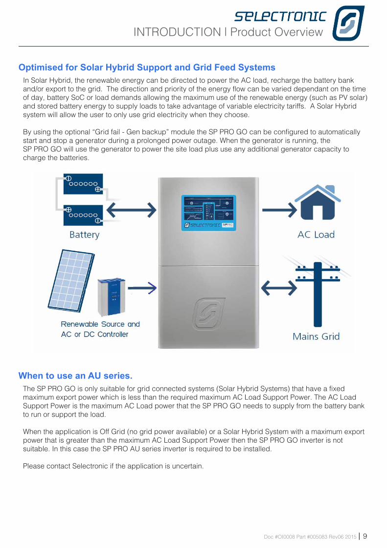
Optimised for Solar Hybrid Support and Grid Feed SystemsIn Solar Hybrid, the renewable energy can be directed to power the AC load, recharge the battery bank and/or export to the grid. The direction and priority of the energy flow can be varied dependant on the time of day, battery SoC or load demands allowing the maximum use of the renewable energy (such as PV solar) and stored battery energy to supply loads to take advantage of variable electricity tariffs. A Solar Hybrid system will allow the user to only use grid electricity when they choose.
By using the optional “Grid fail - Gen backup” module the SP PRO GO can be configured to automatically start and stop a generator during a prolonged power outage. When the generator is running, the SP PRO GO will use the generator to power the site load plus use any additional generator capacity to charge the batteries.
When to use an AU series.The SP PRO GO is only suitable for grid connected systems (Solar Hybrid Systems) that have a fixed maximum export power which is less than the required maximum AC Load Support Power. The AC Load Support Power is the maximum AC Load power that the SP PRO GO needs to supply from the battery bank to run or support the load.
When the application is Off Grid (no grid power available) or a Solar Hybrid System with a maximum export power that is greater than the maximum AC Load Support Power then the SP PRO GO inverter is not suitable. In this case the SP PRO AU series inverter is required to be installed.
Please contact Selectronic if the application is uncertain.
INSTALLATION | Precautions and Safety
10 | Doc #OI0008 Part #005083 Rev06 2015
Warning: If this equipment is used in a manner not specified by the manufacturer as contained in this manual and other operational documents and Instructions, then the protection provided by the equipment may be impaired.
Who should install this unitWhile the SP PRO GO is designed for easy installation and can be installed by any suitably qualified person, to maximize the performance of the system and tailor the configuration of the SP PRO GO to the specific needs we recommend the use of a Selectronic Accredited Integrator. These selected professionals within the industry have been extensively trained to analyse the system requirements, design ancillary equipment and have access to specialist support within Selectronic to assist with any individual requirements.
The voltages produced within a power system are hazardous. Even though the SP PRO GO may derive its input from a battery, the extremely high current capability of a battery bank is hazardous. Additionally the high voltage battery banks (120V) used in the SPMC1201, SPLC1200 and SPLC1202 are hazardous and the output and input AC voltage in all the SP PRO GO models is just a hazardous as grid electricity.
All AC connections and hazardous DC connections to the SP PRO GO must be carried out by a qualified Electrical contractor or similar, failure to do so will contravene legal requirements.
All DC wiring must be carried out by a person experienced with DC electrical circuits and must understand high current low voltage circuits. To ensure an efficient system installation, cable sizing and voltage drop must be understood and the recommendations within this manual followed.
Selectronic Australia shall have no obligation as to any equipment which has been improperly installed, stored, or handled, or which has not been operated or maintained according to this manual, nor for any operating mistakes and consequences arising from them.
This product is not to be used for Life Support equipment
Multiple Hazardous Energy SourcesHazardous voltages and energy are generated by the SP PRO GO They are fed into the SP PRO GO by external wiring from multiple sources and may be stored in capacitors after the SP PRO GO is switched off and disconnected from external wiring.
Precaut ions and Safe tyChapte r Two
INSTALLATION | Precautions and Safety
Doc #OI0008 Part #005083 Rev06 2015 | 11
PreparationWhilst every effort has been made to pack the SP PRO GO in a way that will provide adequate protection, damage in transit can occur. Please carefully check the packaging and the SP PRO GO for signs of damage and for all components mentioned in the “Included in the Package” section of this manual.
Please report any damage or missing parts to Selectronic or a Selectronic Authorised Distributor.
Please retain the original packaging for the safest and most effective method of repackaging if required.
Installation• The SP PRO GO requires adequate ventilation, away from hot equipment. Do not obstruct
the airflow passage of the SP PRO GO case (top and bottom). Ensure when installed in an enclosed space that there is adequate ventilation.
• The SP PRO GO must be located in a place away from electrolyte and corrosive aerosols.• The SP PRO GO contains arcing contacts so must not be located near explosive gas
mixtures such as hydrogen from batteries or diesel fumes.
MaintenanceEnsure that all energy sources are isolated before working on connected wiring. A backup generator may start or power may be restored by the SP PRO GO at any time. Never work on equipment or investigate a problem without following appropriate safety isolation procedures.
Inverter may start automaticallyThe SP PRO GO automatically starts and/or restarts and may restore power at any time. If a fault or overload is detected the SP PRO GO will shutdown and may automatically attempt to restart at varying intervals of up to several hours.
Backup Generator may start automaticallyThe SP PRO GO automatically starts and/or restarts a backup generator (when a Grid Fail - Gen Backup option is installed). If a fault or overload caused the SP PRO GO to shutdown then it will automatically attempt to start and restart the backup generator.
BatteryBatteries are very dangerous. Please read the safety information provided by the battery supplier.
• Battery acid is dangerous.• Batteries can emit hydrogen gas, which is explosive.• Batteries connected in series can produce hazardous voltages.• Disconnecting a DC power connection (even on one battery cell) can cause dangerous high-energy DC
arcs, which can cause serious burns and eject hot particles, and can be difficult to extinguish.• Disconnecting a DC power connection (even on one battery cell) can cause renewable sources to
produce large voltages (much larger than the battery voltage) on battery terminals and DC wiring. Such voltages can be lethal. They can also damage the SP PRO GO. Only suitably trained and qualified personnel should disconnect any DC power connection, including battery cell connections, and only with suitable procedures and safety precautions.
• System battery voltages of 60 V or greater are to be treated as a hazardous voltage.
INSTALLATION | General Requirements
12 | Doc #OI0008 Part #005083 Rev06 2015
Instal lation-Genera l Requ i rementsChapte r Th ree
The SP PRO GO must only be installed by suitably qualified personnel.Many procedures covered in the INSTALLATION sections of this manual have inherent risks. Whilst the SP PRO GO is designed to be safe, including safety features never before found in an inverter (such as Earth / Neutral bond monitoring), the voltages connected to or generated within the SP PRO GO are hazardous and potentially fatal.
It is the responsibility of the installer to ensure the installation and all the wiring is carried out according to all safety standards that are applicable to the installation. The wiring diagrams and installation instructions are given as a guide only and compliance to appropriate standards is the responsibility of the installer.
The following section provides general installation instructions for the SP PRO GO . For information on specific configurations please refer to the “Installation-Specific Applications” Section in this manual and the relevant installation guide supplied with any required installation options.
All installation notes including this manual can be downloaded from the Selectronic web site at:www.selectronic.com.au
INSTALLATION
INSTALLATION | General Requirements
Doc #OI0008 Part #005083 Rev06 2015 | 13
Environmental ConsiderationsENVIRONMENTAL CATEGORYThe SP PRO GO is design with an Environmental Category (as defined by IEC 62109.1) for “Indoor, unconditioned. The SP PRO GO must be protected by a building or enclosure from direct rain, sun, wind-blown dust, fungus and radiation to the night sky. The SP PRO GO must be installed in a dry environment.
POLLUTION DEGREE 2The SP PRO GO is designed to operate in a Pollution Degree 2 environment. Normally only non-conductive pollution occurs with occasional temporary conduction due to condensation expected.
TEMPERATUREThe SP PRO GO is designed for an ambient operating temperature between -20°C and 60°C, with a storage temperature range between –20°C and 70°C.
AIR FLOWFor best performance ensure nothing impedes ambient air from being drawn in the bottom of the unit and that hot exit air is vented away and doesn’t recirculate into the unit. Particular attention must be paid when installed inside a cabinet or enclosure.
CLEARANCE FROM OTHER EQUIPMENTA recommended clearance distance of 150 mm around all sides, top and bottom. Particular care must be taken when mounting near other heat producing equipment.
HUMIDITY TOLERANCEThe SP PRO GO is designed to operate in a humidity range of 0 – 99% non condensing.
INGRESS OF PARTICLES The SP PRO GO has been designed to meet IP rating 43 (Protected against solid objects larger than 1.0 mm / protected against water falling as a spray at up to 60 degrees from the vertical).
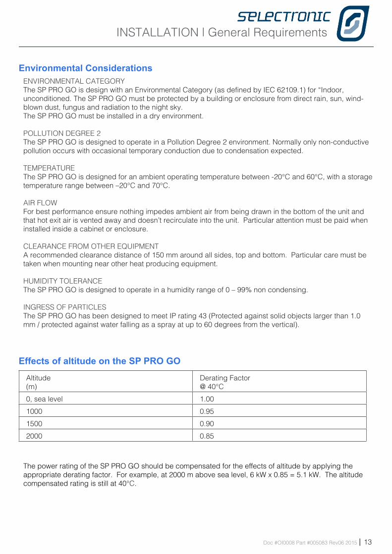
Effects of altitude on the SP PRO GO
Altitude(m)
Derating Factor@ 40°C
0, sea level 1.00
1000 0.95
1500 0.90
2000 0.85
The power rating of the SP PRO GO should be compensated for the effects of altitude by applying the appropriate derating factor. For example, at 2000 m above sea level, 6 kW x 0.85 = 5.1 kW. The altitude compensated rating is still at 40°C.
INSTALLATION | General Requirements
14 | Doc #OI0008 Part #005083 Rev06 2015
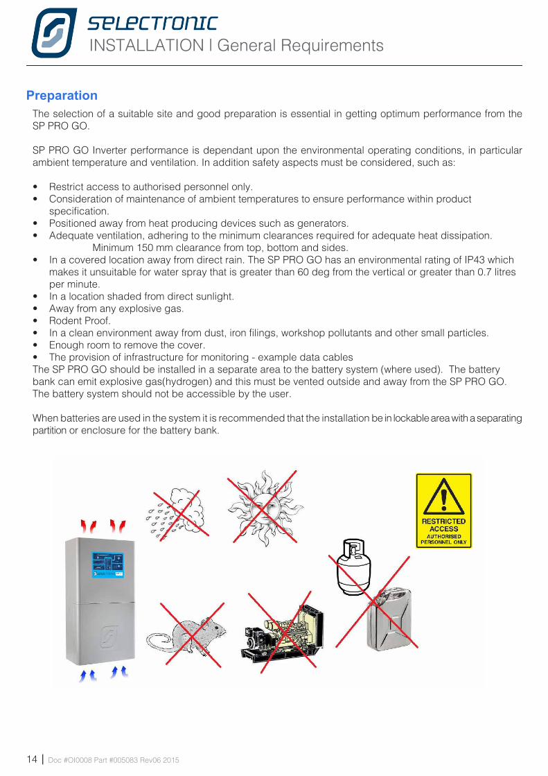
PreparationThe selection of a suitable site and good preparation is essential in getting optimum performance from the SP PRO GO.
SP PRO GO Inverter performance is dependant upon the environmental operating conditions, in particular ambient temperature and ventilation. In addition safety aspects must be considered, such as:
• Restrict access to authorised personnel only.• Consideration of maintenance of ambient temperatures to ensure performance within product
specification.• Positioned away from heat producing devices such as generators.• Adequate ventilation, adhering to the minimum clearances required for adequate heat dissipation.
Minimum 150 mm clearance from top, bottom and sides.• In a covered location away from direct rain. The SP PRO GO has an environmental rating of IP43 which
makes it unsuitable for water spray that is greater than 60 deg from the vertical or greater than 0.7 litres per minute.
• In a location shaded from direct sunlight.• Away from any explosive gas.• Rodent Proof.• In a clean environment away from dust, iron filings, workshop pollutants and other small particles. • Enough room to remove the cover.• The provision of infrastructure for monitoring - example data cablesThe SP PRO GO should be installed in a separate area to the battery system (where used). The battery bank can emit explosive gas(hydrogen) and this must be vented outside and away from the SP PRO GO. The battery system should not be accessible by the user.
When batteries are used in the system it is recommended that the installation be in lockable area with a separating partition or enclosure for the battery bank.
INSTALLATION | Installation of SPMC models
Doc #OI0008 Part #005083 Rev06 2015 | 15
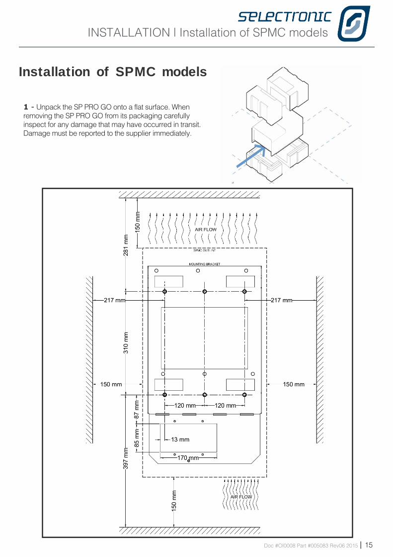
1 - Unpack the SP PRO GO onto a flat surface. When removing the SP PRO GO from its packaging carefully inspect for any damage that may have occurred in transit. Damage must be reported to the supplier immediately.
I ns ta l l a t i on o f SPMC mode ls
INSTALLATION | Installation of SPMC models
16 | Doc #OI0008 Part #005083 Rev06 2015
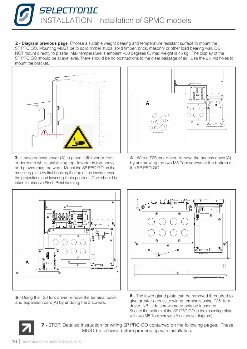
3 - Leave access cover (A) in place. Lift inverter from underneath whilst stabilising top. Inverter is top heavy and gloves must be worn. Mount the SP PRO GO on the mounting plate by first hooking the top of the inverter over the projections and lowering it into position. Care should be taken to observe Pinch Point warning.
4 - With a T25 torx driver, remove the access cover(A) by unscrewing the two M5 Torx screws at the bottom of the SP PRO GO.
5 - Using the T20 torx driver remove the terminal cover and expansion card(A) by undoing the 2 screws.
6 - The lower gland plate can be removed if required to give greater access to wiring terminals using T25 torx driver. NB, side screws need only be loosened.Secure the bottom of the SP PRO GO to the mounting plate with two M5 Torx screws. (A on above diagram)
7 - STOP: Detailed instruction for wiring SP PRO GO contained on the following pages. These MUST be followed before proceeding with installation.
2 - Diagram previous page. Choose a suitable weight bearing and temperature resistant surface to mount the SP PRO GO. Mounting MUST be to solid timber studs, solid timber, brick, masonry or other load bearing wall. DO NOT mount directly to plaster. Max temperature is ambient +30 degrees C, max weight is 45 kg. The display of the SP PRO GO should be at eye level. There should be no obstructions to the clear passage of air. Use the 6 x M8 holes to mount the bracket.
INSTALLATION | Installation of SPMC models
Doc #OI0008 Part #005083 Rev06 2015 | 17
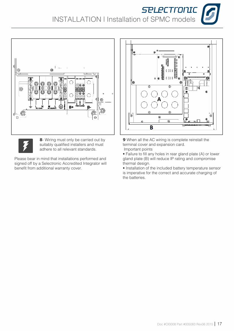
8- Wiring must only be carried out by suitably qualified installers and must adhere to all relevant standards.
Please bear in mind that installations performed and signed off by a Selectronic Accredited Integrator will benefit from additional warranty cover.
9 When all the AC wiring is complete reinstall the terminal cover and expansion card. Important points• Failure to fill any holes in rear gland plate (A) or lower gland plate (B) will reduce IP rating and compromise thermal design.• Installation of the included battery temperature sensor is imperative for the correct and accurate charging of the batteries.
INSTALLATION | Installation of SPLC models
18 | Doc #OI0008 Part #005083 Rev06 2015
I ns ta l l a t i on o f SPLC mode ls
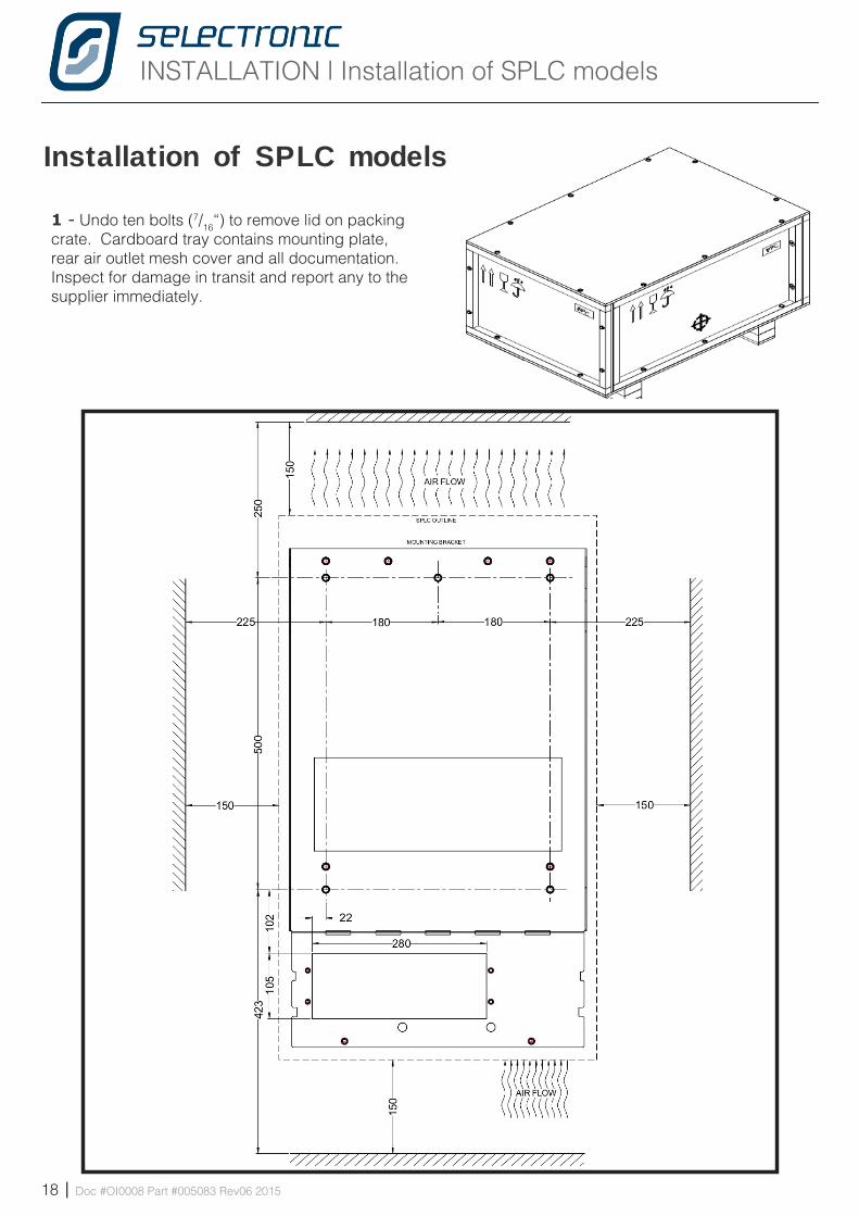
1 - Undo ten bolts (7/16“) to remove lid on packing crate. Cardboard tray contains mounting plate, rear air outlet mesh cover and all documentation.Inspect for damage in transit and report any to the supplier immediately.
INSTALLATION | Installation of SPLC models
Doc #OI0008 Part #005083 Rev06 2015 | 19
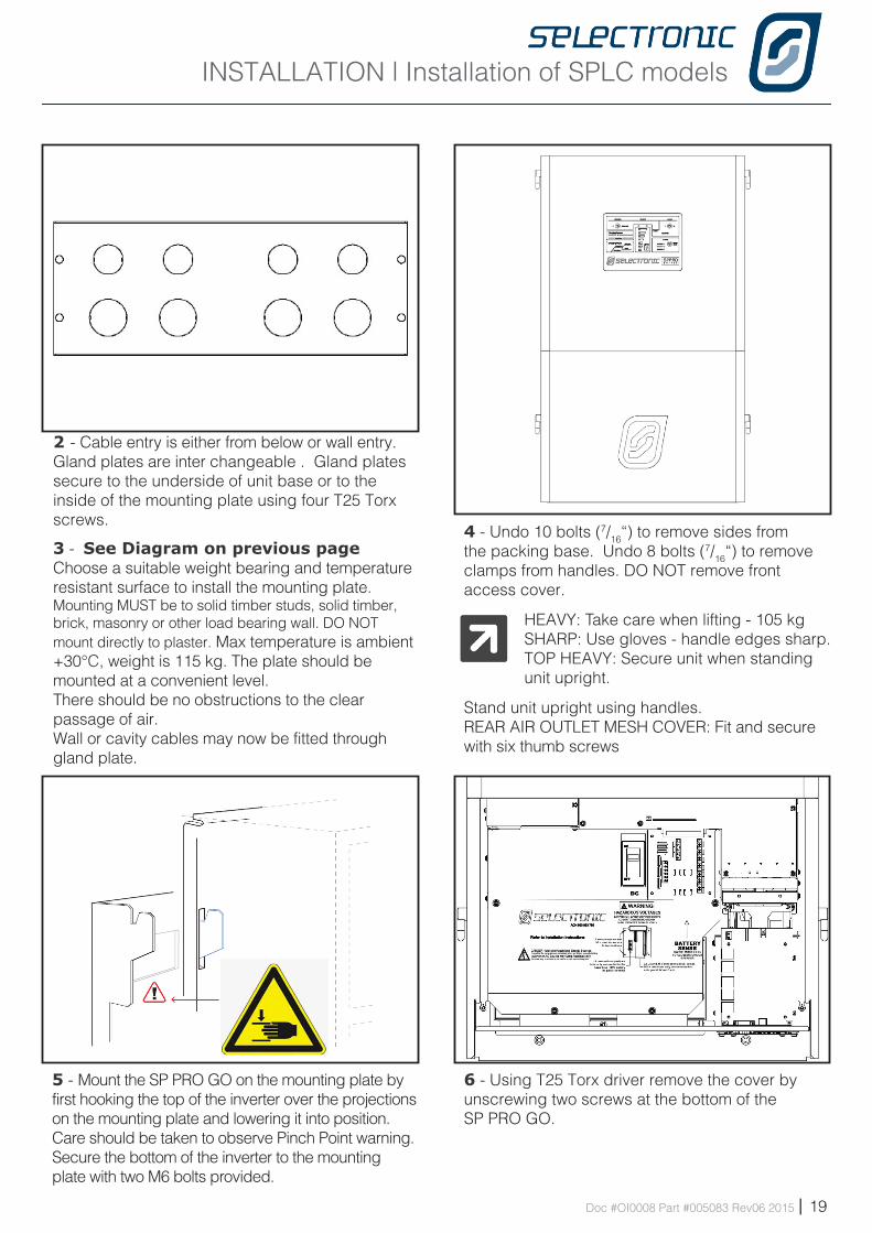
5 - Mount the SP PRO GO on the mounting plate by first hooking the top of the inverter over the projections on the mounting plate and lowering it into position. Care should be taken to observe Pinch Point warning. Secure the bottom of the inverter to the mounting plate with two M6 bolts provided.
6 - Using T25 Torx driver remove the cover by unscrewing two screws at the bottom of the SP PRO GO.
4 - Undo 10 bolts (7/16“) to remove sides from the packing base. Undo 8 bolts (7/16“) to remove clamps from handles. DO NOT remove front access cover.
HEAVY: Take care when lifting - 105 kgSHARP: Use gloves - handle edges sharp.TOP HEAVY: Secure unit when standing unit upright.
Stand unit upright using handles.REAR AIR OUTLET MESH COVER: Fit and secure with six thumb screws
2 - Cable entry is either from below or wall entry. Gland plates are inter changeable . Gland plates secure to the underside of unit base or to the inside of the mounting plate using four T25 Torx screws.
3 - See Diagram on previous pageChoose a suitable weight bearing and temperature resistant surface to install the mounting plate. Mounting MUST be to solid timber studs, solid timber, brick, masonry or other load bearing wall. DO NOT mount directly to plaster. Max temperature is ambient +30°C, weight is 115 kg. The plate should be mounted at a convenient level. There should be no obstructions to the clear passage of air.Wall or cavity cables may now be fitted through gland plate.
INSTALLATION | Installation of SPLC models
20 | Doc #OI0008 Part #005083 Rev06 2015
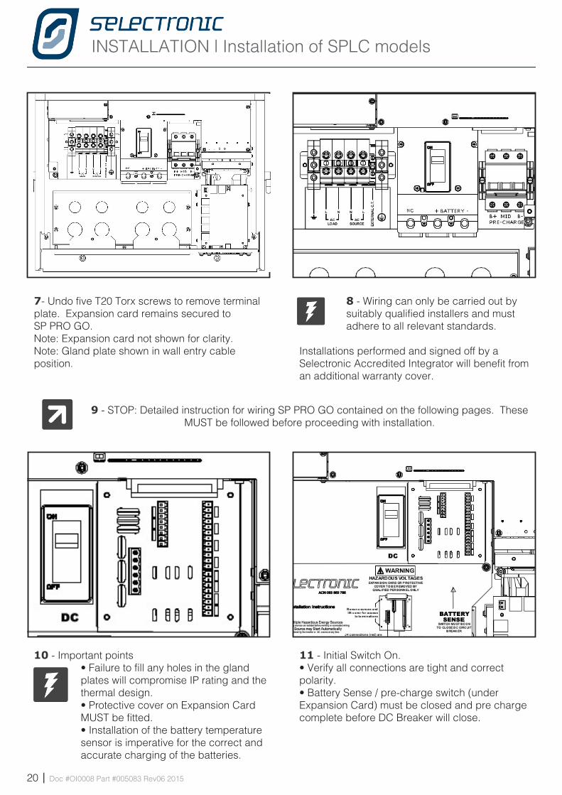
10 - Important points• Failure to fill any holes in the gland plates will compromise IP rating and the thermal design.• Protective cover on Expansion Card MUST be fitted. • Installation of the battery temperature sensor is imperative for the correct and accurate charging of the batteries.
11 - Initial Switch On.• Verify all connections are tight and correct polarity.• Battery Sense / pre-charge switch (under Expansion Card) must be closed and pre charge complete before DC Breaker will close.
7- Undo five T20 Torx screws to remove terminal plate. Expansion card remains secured to SP PRO GO.Note: Expansion card not shown for clarity.Note: Gland plate shown in wall entry cable position.
8 - Wiring can only be carried out by suitably qualified installers and must adhere to all relevant standards.
Installations performed and signed off by a Selectronic Accredited Integrator will benefit from an additional warranty cover.
9 - STOP: Detailed instruction for wiring SP PRO GO contained on the following pages. These MUST be followed before proceeding with installation.
INSTALLATION | Cabling and fusing
Doc #OI0008 Part #005083 Rev06 2015 | 21
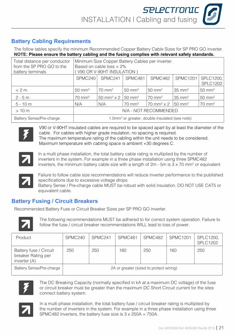
Battery Cabling RequirementsThe follow tables specify the minimum Recommended Copper Battery Cable Sizes for SP PRO GO inverter. NOTE: Please ensure the battery cabling and the fusing complies with relevant safety standards.Total distance per conductor from the SP PRO GO to the battery terminals
Minimum Size Copper Battery Cables per inverter. Based on cable loss < 2%( V90 OR V-90HT INSULATION )
SPMC240 SPMC241 SPMC481 SPMC482 SPMC1201 SPLC1200, SPLC1202
< 2 m 50 mm2 70 mm2 50 mm2 50 mm2 35 mm2 50 mm2
2 - 5 m 70 mm2 50 mm2 x 2 50 mm2 70 mm2 35 mm2 50 mm2
5 - 10 m N/A N/A 70 mm2 70 mm2 x 2 50 mm2 70 mm2
> 10 m N/A - NOT RECOMMENDED
Battery Sense/Pre-charge 1.0mm2 or greater, double insulated (see note)
V90 or V-90HT insulated cables are required to be spaced apart by at least the diameter of the cable. For cables with higher grade insulation, no spacing is required.The maximum temperature rating of the cabling within the unit needs to be considered.Maximum temperature with cabling space is ambient +30 degrees C.
In a multi phase installation, the total battery cable rating is multiplied by the number of inverters in the system. For example in a three phase installation using three SPMC482 inverters, the minimum battery cable size with a length of 2m - 5m is 3 x 70 mm2 or equivalent
Failure to follow cable size recommendations will reduce inverter performance to the published specifications due to excessive voltage drops Battery Sense / Pre-charge cable MUST be robust with solid insulation. DO NOT USE CAT5 or equivalent cable.
Battery Fusing / Circuit BreakersRecommended Battery Fuse or Circuit Breaker Sizes per SP PRO GO inverter.
The following recommendations MUST be adhered to for correct system operation. Failure to follow the fuse / circuit breaker recommendations WILL lead to loss of power.
Product SPMC240 SPMC241 SPMC481 SPMC482 SPMC1201 SPLC1200, SPLC1202
Battery fuse / Circuit breaker Rating per inverter (A)
250 250 160 250 160 250
Battery Sense/Pre-charge 2A or greater (sized to protect wiring)
The DC Breaking Capacity (normally specified in kA at a maximum DC voltage) of the fuse or circuit breaker must be greater than the maximum DC Short Circuit current for the sites connect battery system.
In a multi phase installation, the total battery fuse / circuit breaker rating is multiplied by the number of inverters in the system. For example in a three phase installation using three SPMC482 inverters, the battery fuse size is 3 x 250A = 750A.
INSTALLATION | Cabling and fusing
22 | Doc #OI0008 Part #005083 Rev06 2015
DC Wiring SPMC ModelsWARNING: Copper wiring must be used through out..Observe polarity of ALL battery wiring. Reverse battery polarity will cause irreversible damage.
All the SPMC models do NOT contain an internal fuse or DC breaker. The DC wiring must be fitted with appropriate fusing or circuit breakers.
The fuse or circuit breaker must be located in a user accessible position and be in close proximity to the battery system. The battery system must not be accessible by the user.
There are four DC wiring connections that should be made. B+ and B-, Battery Sense / Pre Charge and optional MID point monitoring. The battery sense / pre-charge connections can be made with light duty cable (1.0 mm2 or greater).
DC wiring should be fed through the appropriate gland and terminated into the correct terminals. Connect the battery negative lead with the insulation stripped back 28 mm to the SP PROs Battery Negative screw terminal. Tighten the hex screw with the driver provided. Repeat the same process with the positive battery lead. Ensure that NO part of the wiring insulation is clamped in the SP PRO GO battery terminals.
Primary DC Terminal Connections - SPLCM8 copper lugs are required to connect battery wiring into the SP PRO GO. SPLC1200 and SPLC1202 models only (All SPMC models are fitted with tunnel terminals for all the DC terminations)Some brands of 70 mm2 lugs may need to be reduced in width to fit within circuit breaker terminal.
DC Terminal Torque settings - SPMC and SPLC
SPMC Main DC Terminals SPLC Main DC Terminals SPMC & SPLC Pre-charge terminals
6.0 to 7.0 Nm 10 to 12 Nm 1.2 to 1.4Nm
DC Wiring SPLC ModelsWARNING: Copper wiring must be used through out..
The SPLC1200 and SPLC1202 models contain a 250 A DC circuit breaker and a low current Battery Sense / Pre charge DC switch. It may be necessary to fit additional fusing or circuit breakers to protect the battery system. Any additional fuse or circuit breaker must be located in a user accessible position and be in close proximity to the battery system. The battery system is hazardous and must not be accessible by the user.
DC wiring should be fed through the appropriate gland and terminated to the correct terminals.
Battery B+ and B- connections. Connect the battery negative lead using M8 copper lug to the SP PROs B- terminal. Tighten the hex screw including load washer with the 6 mm Allen key such that load washer flattens. Repeat the same process with the positive battery lead. The terminal labelled “NC” provides no internal connection.
Battery Sense / Pre charge B+ and B- and optional MID connections. These connections can be made with light duty cable (1.0 mm2 or greater) - cable MUST be double insulated. Connect the battery negative lead with the insulation stripped back 12 mm to the SP PROs Pre charge negative screw terminal. Repeat the same process with the positive battery lead and optional mid point lead.
Multiple Hazardous Energy and Voltage SourcesDC wiring is fed from multiple sources including internal capacitors. Care must be taken to ensure that under no circumstances can the user access or touch wiring even after the operation of external circuit breakers or fuse assemblies.SPMC1201, SPLC1200 and SPLC1202 models operate from a hazardous DC voltage (120VDC). Care MUST be taken to ensure users cannot come in contact with the DC supply.
INSTALLATION | Cabling and fusing
Doc #OI0008 Part #005083 Rev06 2015 | 23
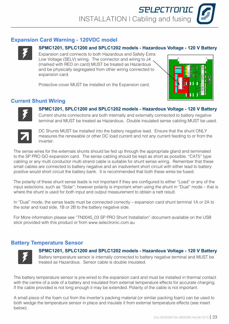
Expansion Card Warning - 120VDC modelSPMC1201, SPLC1200 and SPLC1202 models - Hazardous Voltage - 120 V BatteryExpansion card connects to both Hazardous and Safety Extra Low Voltage (SELV) wiring. The connector and wiring to J4 (marked with RED on card) MUST be treated as Hazardous and be physically segregated from other wiring connected to expansion card.
Protective cover MUST be installed on the Expansion card.
Current Shunt WiringSPMC1201, SPLC1200 and SPLC1202 models - Hazardous Voltage - 120 V BatteryCurrent shunts connections are both internally and externally connected to battery negative terminal and MUST be treated as Hazardous. Double insulated sense cabling MUST be used.
DC Shunts MUST be installed into the battery negative lead. Ensure that the shunt ONLY measures the renewable or other DC load current and not any current feeding to or from the inverter.
The sense wires for the externals shunts should be fed up through the appropriate gland and terminated to the SP PRO GO expansion card. The sense cabling should be kept as short as possible. “CAT5” type cabling or any multi conductor multi strand cable is suitable for shunt sense wiring. Remember that these small cables are connected to battery negative and an inadvertent short circuit with either lead to battery positive would short circuit the battery bank. It is recommended that both these wires be fused.
The polarity of these shunt sense leads is not important if they are configured to either “Load” or any of the input selections, such as “Solar”; however polarity is important when using the shunt in “Dual” mode – that is where the shunt is used for both input and output measurement to obtain a nett result.
In “Dual” mode, the sense leads must be connected correctly – expansion card shunt terminal 1A or 2A to the solar and load side, 1B or 2B to the battery negative side.
For More information please see “TN0045_03 SP PRO Shunt Installation” document available on the USB stick provided with this product or from www.selectronic.com.au
Battery Temperature SensorSPMC1201, SPLC1200 and SPLC1202 models - Hazardous Voltage - 120 V BatteryBattery temperature sensor is internally connected to battery negative terminal and MUST be treated as Hazardous. Sensor cable is double insulated.
The battery temperature sensor is pre-wired to the expansion card and must be installed in thermal contact with the centre of a side of a battery and insulated from external temperature effects for accurate charging. If the cable provided is not long enough it may be extended. Polarity of the cable is not important.
A small piece of the foam cut from the inverter’s packing material (or similar packing foam) can be used to both wedge the temperature sensor in place and insulate it from external temperature effects (see insert below).
INSTALLATION | Cabling and fusing
24 | Doc #OI0008 Part #005083 Rev06 2015
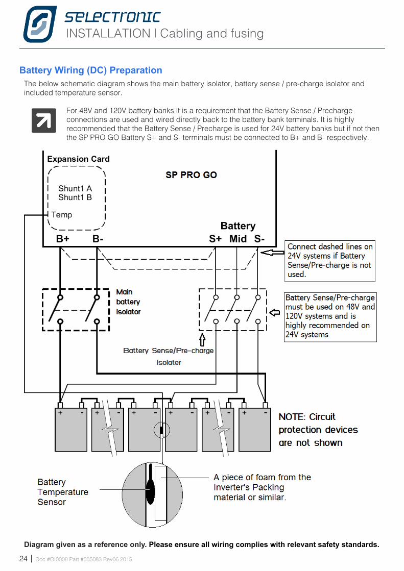
Battery Wiring (DC) PreparationThe below schematic diagram shows the main battery isolator, battery sense / pre-charge isolator and included temperature sensor.
For 48V and 120V battery banks it is a requirement that the Battery Sense / Precharge connections are used and wired directly back to the battery bank terminals. It is highly recommended that the Battery Sense / Precharge is used for 24V battery banks but if not then the SP PRO GO Battery S+ and S- terminals must be connected to B+ and B- respectively.
Diagram given as a reference only. Please ensure all wiring complies with relevant safety standards.
INSTALLATION | Cabling and fusing
Doc #OI0008 Part #005083 Rev06 2015 | 25
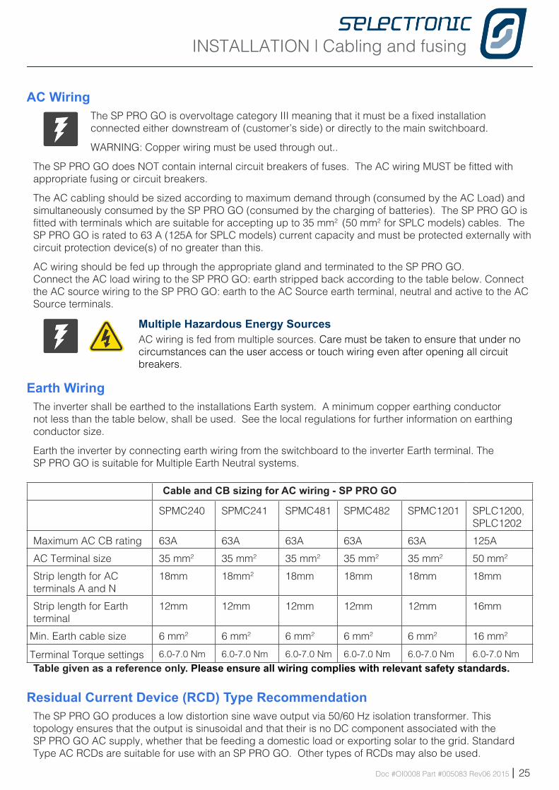
AC WiringThe SP PRO GO is overvoltage category III meaning that it must be a fixed installation connected either downstream of (customer’s side) or directly to the main switchboard.
WARNING: Copper wiring must be used through out..
The SP PRO GO does NOT contain internal circuit breakers of fuses. The AC wiring MUST be fitted with appropriate fusing or circuit breakers.
The AC cabling should be sized according to maximum demand through (consumed by the AC Load) and simultaneously consumed by the SP PRO GO (consumed by the charging of batteries). The SP PRO GO is fitted with terminals which are suitable for accepting up to 35 mm2 (50 mm2 for SPLC models) cables. The SP PRO GO is rated to 63 A (125A for SPLC models) current capacity and must be protected externally with circuit protection device(s) of no greater than this.
AC wiring should be fed up through the appropriate gland and terminated to the SP PRO GO.Connect the AC load wiring to the SP PRO GO: earth stripped back according to the table below. Connect the AC source wiring to the SP PRO GO: earth to the AC Source earth terminal, neutral and active to the AC Source terminals.
Multiple Hazardous Energy SourcesAC wiring is fed from multiple sources. Care must be taken to ensure that under no circumstances can the user access or touch wiring even after opening all circuit breakers.
Earth WiringThe inverter shall be earthed to the installations Earth system. A minimum copper earthing conductor not less than the table below, shall be used. See the local regulations for further information on earthing conductor size.
Earth the inverter by connecting earth wiring from the switchboard to the inverter Earth terminal. The SP PRO GO is suitable for Multiple Earth Neutral systems.
Cable and CB sizing for AC wiring - SP PRO GO
SPMC240 SPMC241 SPMC481 SPMC482 SPMC1201 SPLC1200, SPLC1202
Maximum AC CB rating 63A 63A 63A 63A 63A 125A
AC Terminal size 35 mm2 35 mm2 35 mm2 35 mm2 35 mm2 50 mm2
Strip length for AC terminals A and N
18mm 18mm2 18mm 18mm 18mm 18mm
Strip length for Earth terminal
12mm 12mm 12mm 12mm 12mm 16mm
Min. Earth cable size 6 mm2 6 mm2 6 mm2 6 mm2 6 mm2 16 mm2
Terminal Torque settings 6.0-7.0 Nm 6.0-7.0 Nm 6.0-7.0 Nm 6.0-7.0 Nm 6.0-7.0 Nm 6.0-7.0 Nm
Table given as a reference only. Please ensure all wiring complies with relevant safety standards.
Residual Current Device (RCD) Type RecommendationThe SP PRO GO produces a low distortion sine wave output via 50/60 Hz isolation transformer. This topology ensures that the output is sinusoidal and that their is no DC component associated with the SP PRO GO AC supply, whether that be feeding a domestic load or exporting solar to the grid. Standard Type AC RCDs are suitable for use with an SP PRO GO. Other types of RCDs may also be used.
INSTALLATION | Cabling and fusing
26 | Doc #OI0008 Part #005083 Rev06 2015
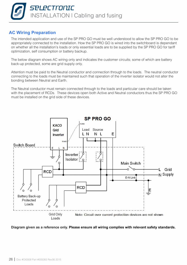
AC Wiring PreparationThe intended application and use of the SP PRO GO must be well understood to allow the SP PRO GO to be appropriately connected to the installation. How the SP PRO GO is wired into the switchboard is dependant on whether all the installation’s loads or only essential loads are to be supplied by the SP PRO GO for tariff optimization, self consumption or battery backup.
The below diagram shows AC wiring only and indicates the customer circuits; some of which are battery back-up protected, some are grid supply only.
Attention must be paid to the Neutral conductor and connection through to the loads. The neutral conductor connecting to the loads must be maintained such that operation of the inverter isolator would not alter the bonding between Neutral and Earth.
The Neutral conductor must remain connected through to the loads and particular care should be taken with the placement of RCDs. These devices open both Active and Neutral conductors thus the SP PRO GO must be installed on the grid side of these devices.
Diagram given as a reference only. Please ensure all wiring complies with relevant safety standards.
INSTALLATION | Cabling and fusing
Doc #OI0008 Part #005083 Rev06 2015 | 27
Backup Generator (Advanced Feature) Control WiringWhen a backup generator is installed, control wiring should be fed up through the appropriate gland and terminated to the SP PRO GO Expansion card. The minimum required is one pair of wires for a generator run signal which must be wired to one of the four relay outputs. “CAT5” type cabling or any multi conductor multi strand cable is suitable for all control wiring. The Expansion Card can be plugged in and out of the SP PRO GO for ease of wiring.
Serial Port ConnectionThe communication cable can be attached to either the USB or DB9 connections on the lower panel.
Only one device maybe connected at any one time to either the USB or DB9. Unused device must be unplugged from its connector.Battery power must be connected to be able to communicate with the SP PRO GO.
Gland Plate Fit outTo maintain the IP rating and safety approval of the SP PRO GO, all gland plate holes must be completely filled and all gland plates fitted correctly. Any gaps including empty gland holes are entry points for vermin and could effect thermal performance.
Gland plates supplied with the SP PRO GO have “knock outs” for ease of installation. Please do not “knock out” any unused gland holes and ensure all used holes have gland nuts (supplied) fitted.
Initial Start up ProcedureBefore turning on the SP PRO GO:• Check all connections, paying particular attention to correct polarity. Give each cable a firm tug to
ensure they are securely fitted. • When satisfied everything is well, attach the terminal cover plate and insert and secure the expansion
card. • For SPMC1201, SPLC1200 and SPLC1202 models - Protective cover MUST be installed on Expansion
card.• Close the battery sense / pre charge circuit breaker/fuses and wait until all indicators are lit and stable.• Close Main battery circuit breaker/fuses.• Press ON button (long press > 1 second) once. The AC Load indicator will be steady blue.• Start using the SP PRO GO by switching on external AC circuit breakers.
For SPMC1201, SPLC1200 and SPLC1202 models - Check protective cover is installed on Expansion card.
• Replace cover and secure with two screws from below.
LabellingRegulations mandate the application of warning and control labels to the various circuit breakers, isolators and switch boards in the installation.
The SP PRO GO will continue to provide power to the load upon interruption of mains supply. Warning signs must indicate which circuits or switchboards operate in this manner.
For examples of labelling that contain Start up and shutdown procedures please refer to the Appendix in the MyGrid installation Note IN0027_0x 005048 myGrid Installation Notes_Found at http://www.selectronic.com.au
INSTALLATION | System Configuration
28 | Doc #OI0008 Part #005083 Rev06 2015
Chapte r Fou r
I ns ta l l a t i on-System Conf igu ra t i on
The SP PRO GO Sine wave Interactive Inverter Charger has been optimised for Solar Hybrid (grid support / grid feed) systems simplifying its installation and configuration. This section details the extra information needed to install and configure standard system configurations. It is imperative that the installation details in the previous section have been followed before proceeding with the relevant installation instructions in this section.
INSTALLATION | System Configuration
Doc #OI0008 Part #005083 Rev06 2015 | 29
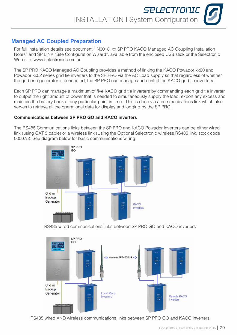
Managed AC Coupled PreparationFor full installation details see document “IN0018_xx SP PRO KACO Managed AC Coupling Installation Notes” and SP LINK “Site Configuration Wizard”. available from the enclosed USB stick or the Selectronic Web site: www.selectronic.com.au The SP PRO KACO Managed AC Coupling provides a method of linking the KACO Powador xx00 and Powador xx02 series grid tie inverters to the SP PRO via the AC Load supply so that regardless of whether the grid or a generator is connected, the SP PRO can manage and control the KACO grid tie inverters.
Each SP PRO can manage a maximum of five KACO grid tie inverters by commanding each grid tie inverter to output the right amount of power that is needed to simultaneously supply the load, export any excess and maintain the battery bank at any particular point in time. This is done via a communications link which also serves to retrieve all the operational data for display and logging by the SP PRO.
Communications between SP PRO GO and KACO inverters
The RS485 Communications links between the SP PRO and KACO Powador inverters can be either wired link (using CAT 5 cable) or a wireless link (Using the Optional Selectronic wireless RS485 link, stock code 005075). See diagram below for basic communications wiring
RS485 wired communications links between SP PRO GO and KACO inverters
RS485 wired AND wireless communications links between SP PRO GO and KACO inverters
INSTALLATION | System Configuration
30 | Doc #OI0008 Part #005083 Rev06 2015
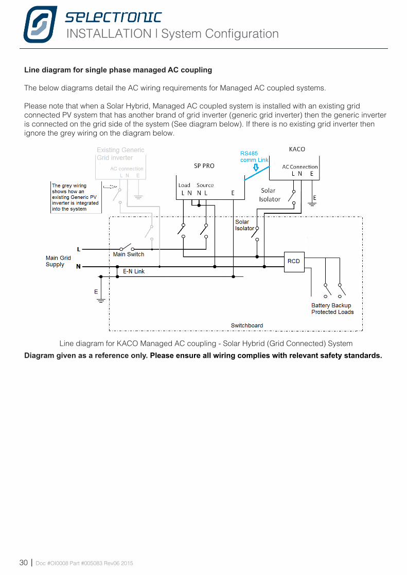
Line diagram for single phase managed AC coupling
The below diagrams detail the AC wiring requirements for Managed AC coupled systems.
Please note that when a Solar Hybrid, Managed AC coupled system is installed with an existing grid connected PV system that has another brand of grid inverter (generic grid inverter) then the generic inverter is connected on the grid side of the system (See diagram below). If there is no existing grid inverter then ignore the grey wiring on the diagram below.
Line diagram for KACO Managed AC coupling - Solar Hybrid (Grid Connected) System
Diagram given as a reference only. Please ensure all wiring complies with relevant safety standards.
INSTALLATION | System Configuration
Doc #OI0008 Part #005083 Rev06 2015 | 31
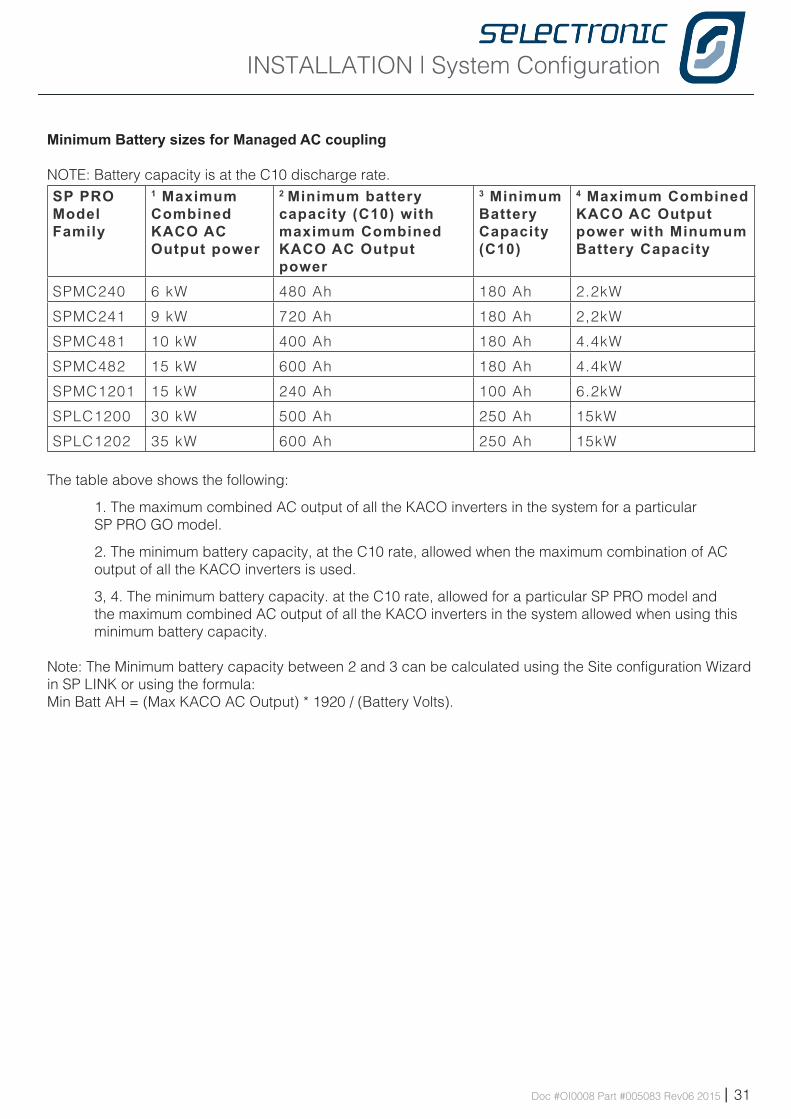
Minimum Battery sizes for Managed AC coupling
NOTE: Battery capacity is at the C10 discharge rate.SP PRO Model Family
1 Maximum Combined KACO AC Output power
2 Minimum battery capacity (C10) with maximum Combined KACO AC Output power
3 Minimum Battery Capacity (C10)
4 Maximum Combined KACO AC Output power with Minumum Battery Capacity
SPMC240 6 kW 480 Ah 180 Ah 2.2kW
SPMC241 9 kW 720 Ah 180 Ah 2,2kW
SPMC481 10 kW 400 Ah 180 Ah 4.4kW
SPMC482 15 kW 600 Ah 180 Ah 4.4kW
SPMC1201 15 kW 240 Ah 100 Ah 6.2kW
SPLC1200 30 kW 500 Ah 250 Ah 15kW
SPLC1202 35 kW 600 Ah 250 Ah 15kW
The table above shows the following:
1. The maximum combined AC output of all the KACO inverters in the system for a particular SP PRO GO model.
2. The minimum battery capacity, at the C10 rate, allowed when the maximum combination of AC output of all the KACO inverters is used.
3, 4. The minimum battery capacity. at the C10 rate, allowed for a particular SP PRO model and the maximum combined AC output of all the KACO inverters in the system allowed when using this minimum battery capacity.
Note: The Minimum battery capacity between 2 and 3 can be calculated using the Site configuration Wizard in SP LINK or using the formula:Min Batt AH = (Max KACO AC Output) * 1920 / (Battery Volts).
INSTALLATION | System Configuration
32 | Doc #OI0008 Part #005083 Rev06 2015
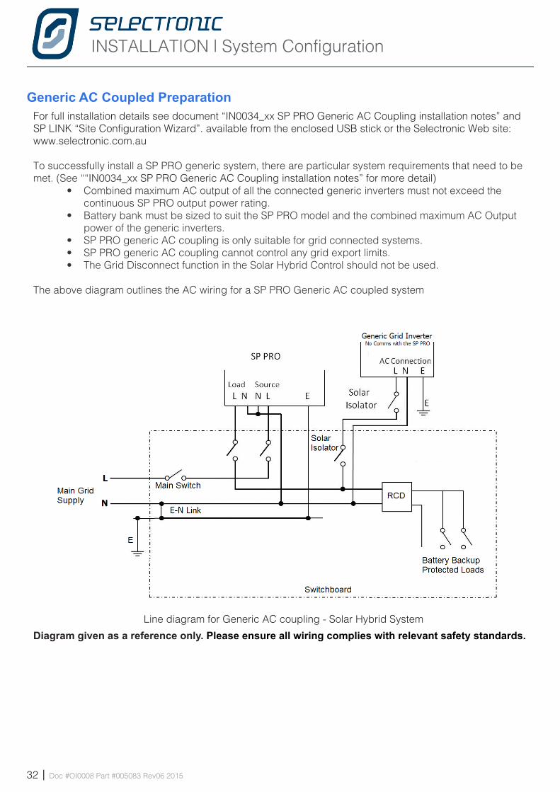
Line diagram for Generic AC coupling - Solar Hybrid System
Generic AC Coupled PreparationFor full installation details see document “IN0034_xx SP PRO Generic AC Coupling installation notes” and SP LINK “Site Configuration Wizard”. available from the enclosed USB stick or the Selectronic Web site: www.selectronic.com.au
To successfully install a SP PRO generic system, there are particular system requirements that need to be met. (See ““IN0034_xx SP PRO Generic AC Coupling installation notes” for more detail)
• Combined maximum AC output of all the connected generic inverters must not exceed the continuous SP PRO output power rating.
• Battery bank must be sized to suit the SP PRO model and the combined maximum AC Output power of the generic inverters.
• SP PRO generic AC coupling is only suitable for grid connected systems.• SP PRO generic AC coupling cannot control any grid export limits.• The Grid Disconnect function in the Solar Hybrid Control should not be used.
The above diagram outlines the AC wiring for a SP PRO Generic AC coupled system
Diagram given as a reference only. Please ensure all wiring complies with relevant safety standards.
INSTALLATION | System Configuration
Doc #OI0008 Part #005083 Rev06 2015 | 33
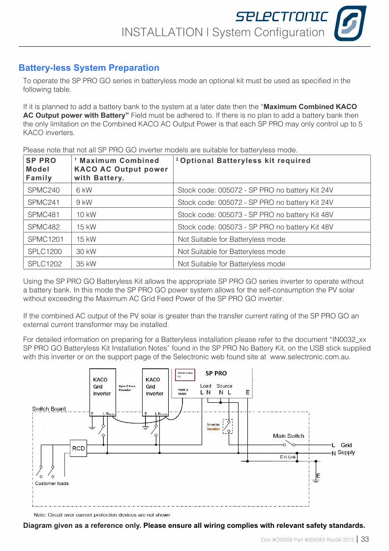
Battery-less System PreparationTo operate the SP PRO GO series in batteryless mode an optional kit must be used as specified in the following table.
If it is planned to add a battery bank to the system at a later date then the “Maximum Combined KACO AC Output power with Battery” Field must be adhered to. If there is no plan to add a battery bank then the only limitation on the Combined KACO AC Output Power is that each SP PRO may only control up to 5 KACO inverters.
Please note that not all SP PRO GO inverter models are suitable for batteryless mode.SP PRO Model Family
1 Maximum Combined KACO AC Output power with Battery.
2 Optional Batteryless kit required
SPMC240 6 kW Stock code: 005072 - SP PRO no battery Kit 24V
SPMC241 9 kW Stock code: 005072 - SP PRO no battery Kit 24V
SPMC481 10 kW Stock code: 005073 - SP PRO no battery Kit 48V
SPMC482 15 kW Stock code: 005073 - SP PRO no battery Kit 48V
SPMC1201 15 kW Not Suitable for Batteryless mode
SPLC1200 30 kW Not Suitable for Batteryless mode
SPLC1202 35 kW Not Suitable for Batteryless mode
Using the SP PRO GO Batteryless Kit allows the appropriate SP PRO GO series inverter to operate without a battery bank. In this mode the SP PRO GO power system allows for the self-consumption the PV solar without exceeding the Maximum AC Grid Feed Power of the SP PRO GO inverter.
If the combined AC output of the PV solar is greater than the transfer current rating of the SP PRO GO an external current transformer may be installed.
For detailed information on preparing for a Batteryless installation please refer to the document “IN0032_xx SP PRO GO Batteryless Kit Installation Notes” found in the SP PRO No Battery Kit, on the USB stick supplied with this inverter or on the support page of the Selectronic web found site at www.selectronic.com.au.
Diagram given as a reference only. Please ensure all wiring complies with relevant safety standards.
INSTALLATION | System Configuration
34 | Doc #OI0008 Part #005083 Rev06 2015
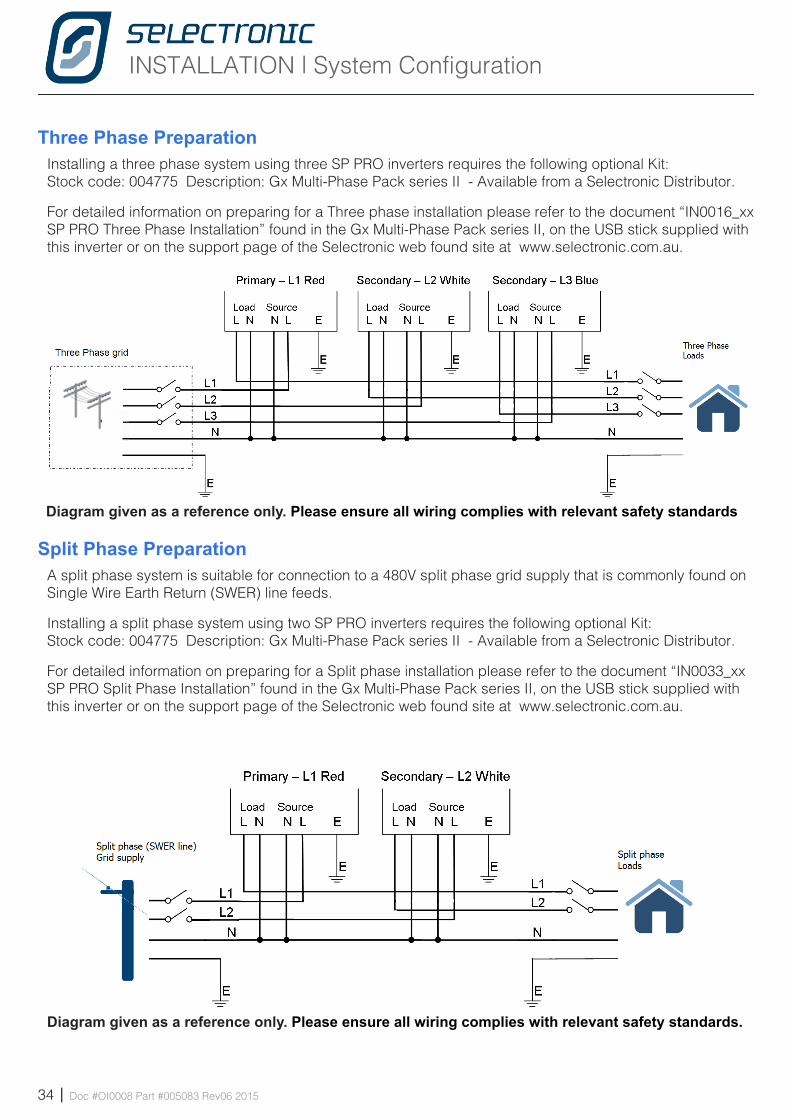
Three Phase PreparationInstalling a three phase system using three SP PRO inverters requires the following optional Kit:Stock code: 004775 Description: Gx Multi-Phase Pack series II - Available from a Selectronic Distributor.
For detailed information on preparing for a Three phase installation please refer to the document “IN0016_xx SP PRO Three Phase Installation” found in the Gx Multi-Phase Pack series II, on the USB stick supplied with this inverter or on the support page of the Selectronic web found site at www.selectronic.com.au.
Split Phase PreparationA split phase system is suitable for connection to a 480V split phase grid supply that is commonly found on Single Wire Earth Return (SWER) line feeds.
Installing a split phase system using two SP PRO inverters requires the following optional Kit:Stock code: 004775 Description: Gx Multi-Phase Pack series II - Available from a Selectronic Distributor.
For detailed information on preparing for a Split phase installation please refer to the document “IN0033_xx SP PRO Split Phase Installation” found in the Gx Multi-Phase Pack series II, on the USB stick supplied with this inverter or on the support page of the Selectronic web found site at www.selectronic.com.au.
Diagram given as a reference only. Please ensure all wiring complies with relevant safety standards
Diagram given as a reference only. Please ensure all wiring complies with relevant safety standards.
INSTALLATION | System Configuration
Doc #OI0008 Part #005083 Rev06 2015 | 35
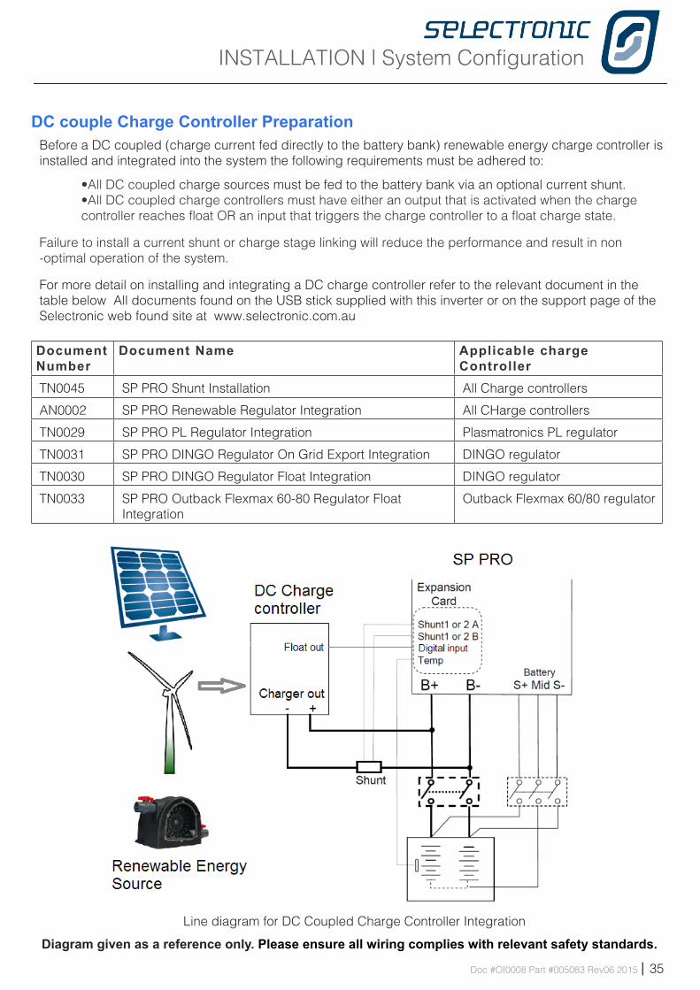
DC couple Charge Controller PreparationBefore a DC coupled (charge current fed directly to the battery bank) renewable energy charge controller is installed and integrated into the system the following requirements must be adhered to:
•All DC coupled charge sources must be fed to the battery bank via an optional current shunt.•All DC coupled charge controllers must have either an output that is activated when the charge controller reaches float OR an input that triggers the charge controller to a float charge state.
Failure to install a current shunt or charge stage linking will reduce the performance and result in non -optimal operation of the system.
For more detail on installing and integrating a DC charge controller refer to the relevant document in the table below All documents found on the USB stick supplied with this inverter or on the support page of the Selectronic web found site at www.selectronic.com.au
Document Number
Document Name Applicable charge Controller
TN0045 SP PRO Shunt Installation All Charge controllers
AN0002 SP PRO Renewable Regulator Integration All CHarge controllers
TN0029 SP PRO PL Regulator Integration Plasmatronics PL regulator
TN0031 SP PRO DINGO Regulator On Grid Export Integration DINGO regulator
TN0030 SP PRO DINGO Regulator Float Integration DINGO regulator
TN0033 SP PRO Outback Flexmax 60-80 Regulator Float Integration
Outback Flexmax 60/80 regulator
Line diagram for DC Coupled Charge Controller Integration
Diagram given as a reference only. Please ensure all wiring complies with relevant safety standards.
INSTALLATION | Ancillary Components
36 | Doc #OI0008 Part #005083 Rev06 2015
I ns ta l l a t i on-Anc i l l a ry ComponentsChapte r F ive
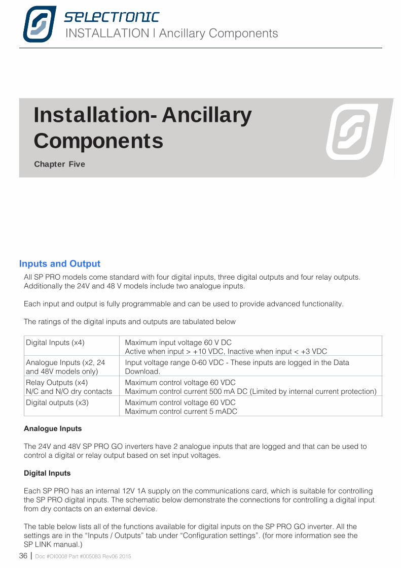
Inputs and OutputAll SP PRO models come standard with four digital inputs, three digital outputs and four relay outputs. Additionally the 24V and 48 V models include two analogue inputs.
Each input and output is fully programmable and can be used to provide advanced functionality.
The ratings of the digital inputs and outputs are tabulated below
Digital Inputs (x4) Maximum input voltage 60 V DC Active when input > +10 VDC, Inactive when input < +3 VDC
Analogue Inputs (x2, 24 and 48V models only)
Input voltage range 0-60 VDC - These inputs are logged in the Data Download.
Relay Outputs (x4)N/C and N/O dry contacts
Maximum control voltage 60 VDCMaximum control current 500 mA DC (Limited by internal current protection)
Digital outputs (x3) Maximum control voltage 60 VDCMaximum control current 5 mADC
Analogue Inputs
The 24V and 48V SP PRO GO inverters have 2 analogue inputs that are logged and that can be used to control a digital or relay output based on set input voltages.
Digital Inputs
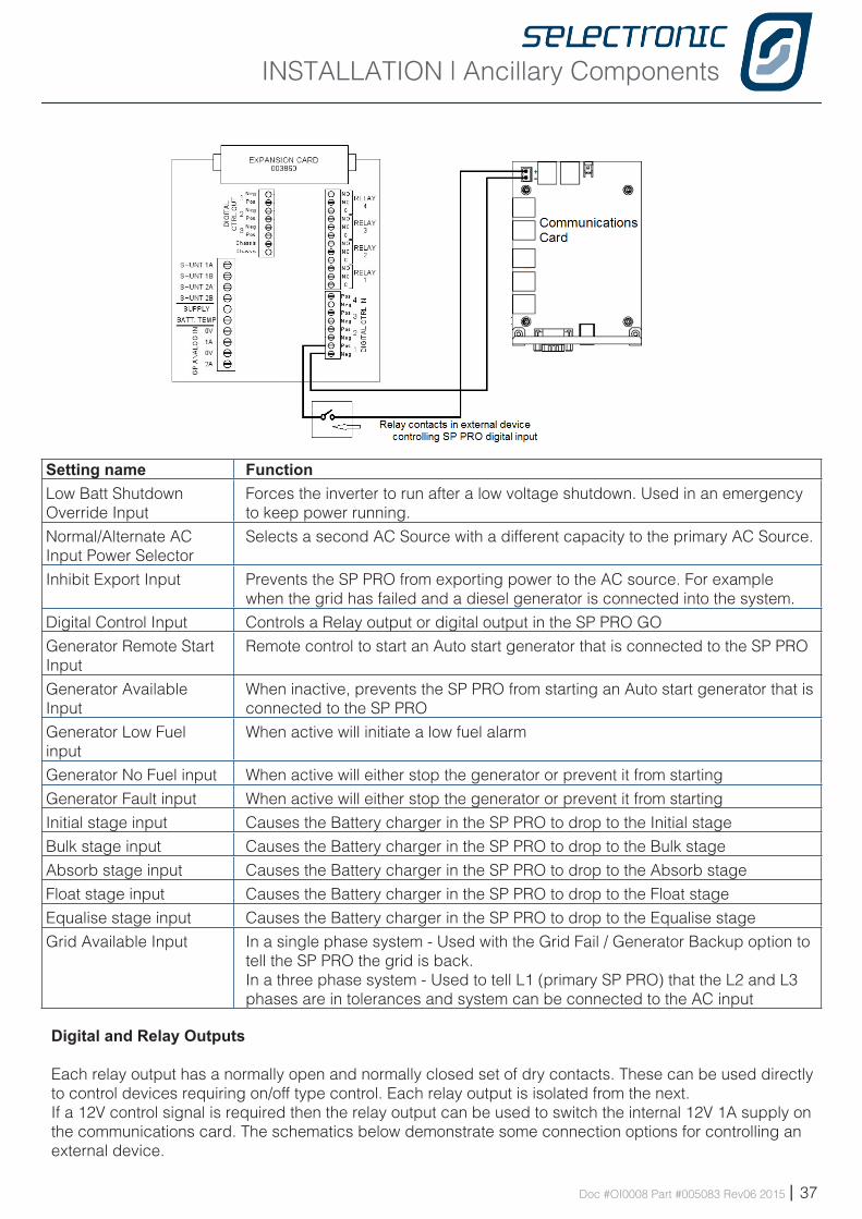
Each SP PRO has an internal 12V 1A supply on the communications card, which is suitable for controlling the SP PRO digital inputs. The schematic below demonstrate the connections for controlling a digital input from dry contacts on an external device.
The table below lists all of the functions available for digital inputs on the SP PRO GO inverter. All the settings are in the “Inputs / Outputs” tab under “Configuration settings”. (for more information see the SP LINK manual.)
INSTALLATION | Ancillary Components
Doc #OI0008 Part #005083 Rev06 2015 | 37
Setting name FunctionLow Batt Shutdown Override Input
Forces the inverter to run after a low voltage shutdown. Used in an emergency to keep power running.
Normal/Alternate AC Input Power Selector
Selects a second AC Source with a different capacity to the primary AC Source.
Inhibit Export Input Prevents the SP PRO from exporting power to the AC source. For example when the grid has failed and a diesel generator is connected into the system.
Digital Control Input Controls a Relay output or digital output in the SP PRO GO
Generator Remote Start Input
Remote control to start an Auto start generator that is connected to the SP PRO
Generator Available Input
When inactive, prevents the SP PRO from starting an Auto start generator that is connected to the SP PRO
Generator Low Fuel input
When active will initiate a low fuel alarm
Generator No Fuel input When active will either stop the generator or prevent it from starting
Generator Fault input When active will either stop the generator or prevent it from starting
Initial stage input Causes the Battery charger in the SP PRO to drop to the Initial stage
Bulk stage input Causes the Battery charger in the SP PRO to drop to the Bulk stage
Absorb stage input Causes the Battery charger in the SP PRO to drop to the Absorb stage
Float stage input Causes the Battery charger in the SP PRO to drop to the Float stage
Equalise stage input Causes the Battery charger in the SP PRO to drop to the Equalise stage
Grid Available Input In a single phase system - Used with the Grid Fail / Generator Backup option to tell the SP PRO the grid is back.In a three phase system - Used to tell L1 (primary SP PRO) that the L2 and L3 phases are in tolerances and system can be connected to the AC input
Digital and Relay Outputs
Each relay output has a normally open and normally closed set of dry contacts. These can be used directly to control devices requiring on/off type control. Each relay output is isolated from the next. If a 12V control signal is required then the relay output can be used to switch the internal 12V 1A supply on the communications card. The schematics below demonstrate some connection options for controlling an external device.
INSTALLATION | Ancillary Components
38 | Doc #OI0008 Part #005083 Rev06 2015
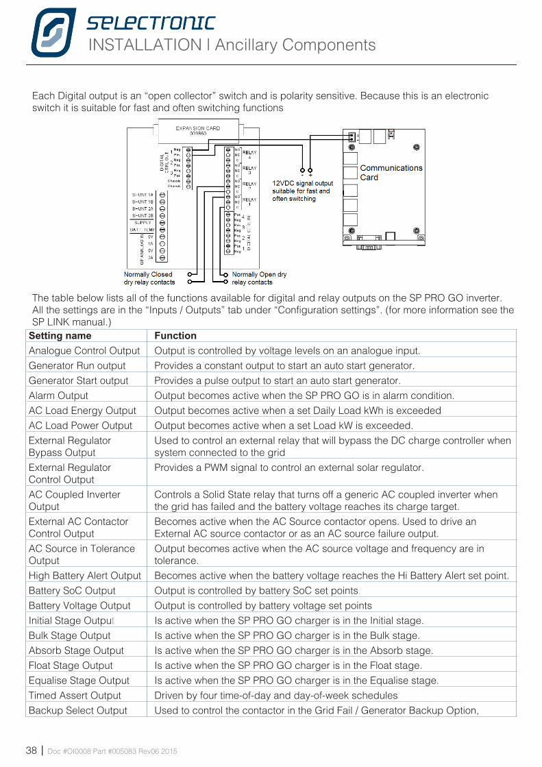
Each Digital output is an “open collector” switch and is polarity sensitive. Because this is an electronic switch it is suitable for fast and often switching functions
The table below lists all of the functions available for digital and relay outputs on the SP PRO GO inverter. All the settings are in the “Inputs / Outputs” tab under “Configuration settings”. (for more information see the SP LINK manual.)
Setting name FunctionAnalogue Control Output Output is controlled by voltage levels on an analogue input.
Generator Run output Provides a constant output to start an auto start generator.
Generator Start output Provides a pulse output to start an auto start generator.
Alarm Output Output becomes active when the SP PRO GO is in alarm condition.
AC Load Energy Output Output becomes active when a set Daily Load kWh is exceeded
AC Load Power Output Output becomes active when a set Load kW is exceeded.
External Regulator Bypass Output
Used to control an external relay that will bypass the DC charge controller when system connected to the grid
External Regulator Control Output
Provides a PWM signal to control an external solar regulator.
AC Coupled Inverter Output
Controls a Solid State relay that turns off a generic AC coupled inverter when the grid has failed and the battery voltage reaches its charge target.
External AC Contactor Control Output
Becomes active when the AC Source contactor opens. Used to drive an External AC source contactor or as an AC source failure output.
AC Source in Tolerance Output
Output becomes active when the AC source voltage and frequency are in tolerance.
High Battery Alert Output Becomes active when the battery voltage reaches the Hi Battery Alert set point.
Battery SoC Output Output is controlled by battery SoC set points.
Battery Voltage Output Output is controlled by battery voltage set points
Initial Stage Output Is active when the SP PRO GO charger is in the Initial stage.
Bulk Stage Output Is active when the SP PRO GO charger is in the Bulk stage.
Absorb Stage Output Is active when the SP PRO GO charger is in the Absorb stage.
Float Stage Output Is active when the SP PRO GO charger is in the Float stage.
Equalise Stage Output Is active when the SP PRO GO charger is in the Equalise stage.
Timed Assert Output Driven by four time-of-day and day-of-week schedules
Backup Select Output Used to control the contactor in the Grid Fail / Generator Backup Option,
INSTALLATION | Ancillary Components
Doc #OI0008 Part #005083 Rev06 2015 | 39
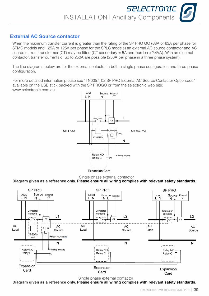
External AC Source contactorWhen the maximum transfer current is greater than the rating of the SP PRO GO (63A or 63A per phase for SPMC models and 125A or 125A per phase for the SPLC models) an external AC source contactor and AC source current transformer (CT) may be fitted (CT secondary = 5A and burden >2.4VA). With an external contactor, transfer currents of up to 250A are possible (250A per phase in a three phase system).
The line diagrams below are for the external contactor in both a single phase configuration and three phase configuration.
For more detailed information please see “TN0057_02 SP PRO External AC Source Contactor Option.doc” available on the USB stick packed with the SP PROGO or from the selectronic web site:www.selectronic.com.au.
Single phase external contactor
Single phase external contactor
Diagram given as a reference only. Please ensure all wiring complies with relevant safety standards.
Diagram given as a reference only. Please ensure all wiring complies with relevant safety standards.
INSTALLATION | Ancillary Components
40 | Doc #OI0008 Part #005083 Rev06 2015
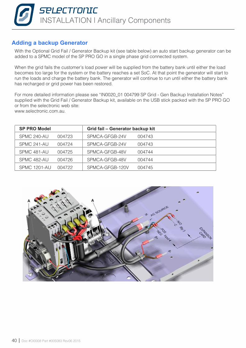
Adding a backup GeneratorWith the Optional Grid Fail / Generator Backup kit (see table below) an auto start backup generator can be added to a SPMC model of the SP PRO GO in a single phase grid connected system.
When the grid fails the customer’s load power will be supplied from the battery bank until either the load becomes too large for the system or the battery reaches a set SoC. At that point the generator will start to run the loads and charge the battery bank. The generator will continue to run until either the battery bank has recharged or grid power has been restored.
For more detailed information please see “IN0020_01 004799 SP Grid - Gen Backup Installation Notes” supplied with the Grid Fail / Generator Backup kit, available on the USB stick packed with the SP PRO GO or from the selectronic web site:www.selectronic.com.au.
SP PRO Model Grid fail – Generator backup kitSPMC 240-AU 004723 SPMCA-GFGB-24V 004743
SPMC 241-AU 004724 SPMCA-GFGB-24V 004743
SPMC 481-AU 004725 SPMCA-GFGB-48V 004744
SPMC 482-AU 004726 SPMCA-GFGB-48V 004744
SPMC 1201-AU 004722 SPMCA-GFGB-120V 004745

Blank Page
Doc #OI0008 Part #005083 Rev06 2015 | 41
INSTALLATION | Communications
42 | Doc #OI0008 Part #005083 Rev06 2015
Chapte r S ix
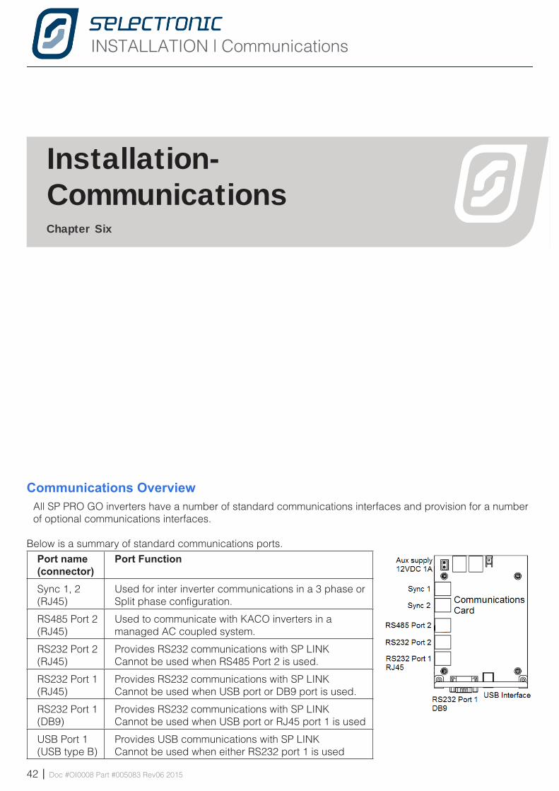
Communications OverviewAll SP PRO GO inverters have a number of standard communications interfaces and provision for a number of optional communications interfaces.
Below is a summary of standard communications ports.Port name(connector)
Port Function
Sync 1, 2 (RJ45)
Used for inter inverter communications in a 3 phase or Split phase configuration.
RS485 Port 2(RJ45)
Used to communicate with KACO inverters in a managed AC coupled system.
RS232 Port 2(RJ45)
Provides RS232 communications with SP LINKCannot be used when RS485 Port 2 is used.
RS232 Port 1(RJ45)
Provides RS232 communications with SP LINKCannot be used when USB port or DB9 port is used.
RS232 Port 1(DB9)
Provides RS232 communications with SP LINKCannot be used when USB port or RJ45 port 1 is used
USB Port 1(USB type B)
Provides USB communications with SP LINKCannot be used when either RS232 port 1 is used
I ns ta l l a t i on-Commun ica t ions
INSTALLATION | Communications
Doc #OI0008 Part #005083 Rev06 2015 | 43
RS232 serial communicationsTo enable communications with legacy interfaces the SP PRO has two RS232 ports.
RS232 Port 1 is provided on either a RJ45 connector or DB9 connector. Only one of these options may be used at any one time and neither can be used when the USB option is connected.
RS232 Port 2 is only provided on a RJ45 connected. This port can only be used when the RS485 Port 2 is not in use.
Below is a summary of available optional communication interfacesOption name FunctionWireless SP PRO to SP LINK(Stock code 004859)
Wirelessly connect the SP PRO to the USB port of the PC running SP LINK
Ethernet Adaptor - LAN(Stock code 005081)
Connect the SP PRO to a Local Area Network (LAN). Allows any PC connected to the LAN to communicate via SP LINK.
Ethernet Adaptor - Internet(Stock code 005081)
Using the same Ethernet adaptor the SP PRO can be connected to the Internet. This requires configuration of the router and advanced knowlege of networks.
Wireless RS485(Stock code 005075)
Provides wireless communications between SP PRO and KACO inverters in a managed AC coupled system
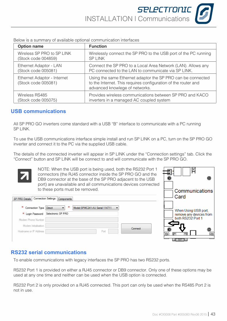
USB communications
All SP PRO GO inverters come standard with a USB “B” interface to communicate with a PC running SP LINK.
To use the USB communications interface simple install and run SP LINK on a PC, turn on the SP PRO GO inverter and connect it to the PC via the supplied USB cable.
The details of the connected inverter will appear in SP LINK under the “Connection settings” tab. Click the “Connect” button and SP LINK will be connect to and will communicate with the SP PRO GO.
NOTE: When the USB port is being used, both the RS232 Port 1 connectors (the RJ45 connector inside the SP PRO GO and the DB9 connector at the base of the SP PRO adjacent to the USB port) are unavailable and all communications devices connected to these ports must be removed.
INSTALLATION | Communications
44 | Doc #OI0008 Part #005083 Rev06 2015
The RS232 ports are wired as DTE with their pinouts listed in the table below.Pin Signal RS232 Port 1 RJ45 Signal RS232 Port 1 DB9 Signal RS232 Port 2 RJ451 +12V 1A supply N/C +12V 1A supply
2 N/C Receive (Input) Data Data Terminal Ready
3 Transmit (Output) Data Transmit (Output) Data Transmit (Output) Data
4 Signal Ground N/C Signal Ground
5 Signal Ground Signal Ground Signal Ground
6 Receive (Input) Data N/C Receive (Input) Data
7 N/C N/C Data Carrier Detect
8 N/C N/C N/C
9 - +12V 1A supply -
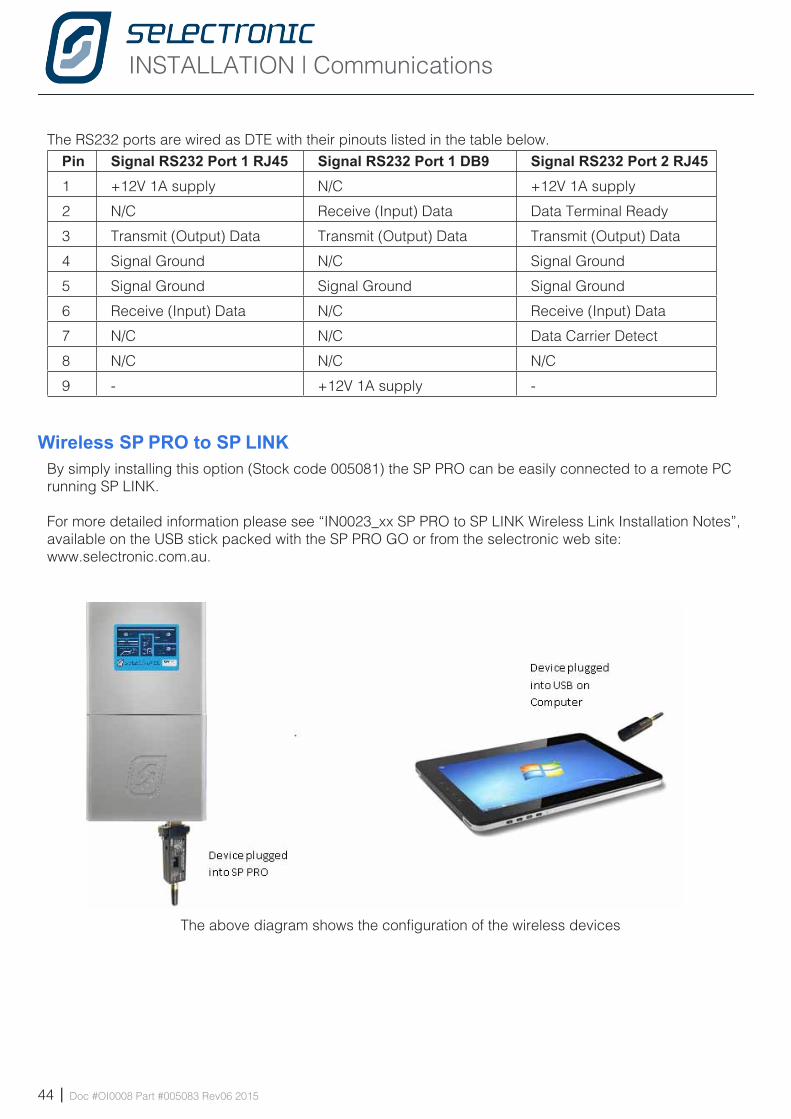
Wireless SP PRO to SP LINKBy simply installing this option (Stock code 005081) the SP PRO can be easily connected to a remote PC running SP LINK.
For more detailed information please see “IN0023_xx SP PRO to SP LINK Wireless Link Installation Notes”, available on the USB stick packed with the SP PRO GO or from the selectronic web site:www.selectronic.com.au.
The above diagram shows the configuration of the wireless devices
INSTALLATION | Communications
Doc #OI0008 Part #005083 Rev06 2015 | 45
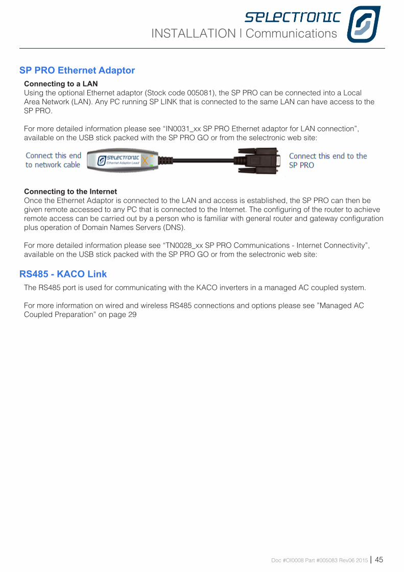
SP PRO Ethernet AdaptorConnecting to a LANUsing the optional Ethernet adaptor (Stock code 005081), the SP PRO can be connected into a Local Area Network (LAN). Any PC running SP LINK that is connected to the same LAN can have access to the SP PRO.
For more detailed information please see “IN0031_xx SP PRO Ethernet adaptor for LAN connection”, available on the USB stick packed with the SP PRO GO or from the selectronic web site: www.selectronic.com.au.
Connecting to the InternetOnce the Ethernet Adaptor is connected to the LAN and access is established, the SP PRO can then be given remote accessed to any PC that is connected to the Internet. The configuring of the router to achieve remote access can be carried out by a person who is familiar with general router and gateway configuration plus operation of Domain Names Servers (DNS).
For more detailed information please see “TN0028_xx SP PRO Communications - Internet Connectivity”, available on the USB stick packed with the SP PRO GO or from the selectronic web site:
RS485 - KACO LinkThe RS485 port is used for communicating with the KACO inverters in a managed AC coupled system.
For more information on wired and wireless RS485 connections and options please see ”Managed AC Coupled Preparation” on page 29
INSTALLATION | Using SP LINK
46 | Doc #OI0008 Part #005083 Rev06 2015
Instal lation-Configure with SP LINKChapte r Seven
Overview
“SP LINK is the pathway to the real power of the SP PRO”
SP PRO GO is optimised for Solar Hybrid (grid connected) power systems and as such is easily configured to suit any Solar Hybrid application.
Use the SP LINK Site Configuration Wizard in the Easy Start Guide to configure the SP PRO GO for most Solar Hybrid applications or access the many advanced parameters to configure the SP PRO GO for a more complex Solar Hybrid system.
SP LINK software is available from the supplied USB stick or download the latest version from the Selectronic Web site at: www.selectronic.com.au.
We strongly suggest that SP LINK is installed on your PC before going to the installation site.
This section of the SP PRO GO manual is an introduction to SP LINK. For detailed information on SP LINK, please consult the SP LINK manual found in the HELP menu within SP LINK or on the USB stick supplied with the SP PRO GO
INSTALLATION | Using SP LINK
Doc #OI0008 Part #005083 Rev06 2015 | 47
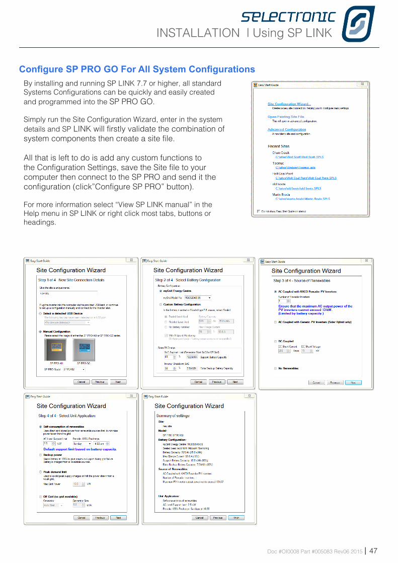
Configure SP PRO GO For All System ConfigurationsBy installing and running SP LINK 7.7 or higher, all standard Systems Configurations can be quickly and easily created and programmed into the SP PRO GO.
Simply run the Site Configuration Wizard, enter in the system details and SP LINK will firstly validate the combination of system components then create a site file.
All that is left to do is add any custom functions to the Configuration Settings, save the Site file to your computer then connect to the SP PRO and send it the configuration (click”Configure SP PRO” button).
For more information select “View SP LINK manual” in the Help menu in SP LINK or right click most tabs, buttons or headings.
INSTALLATION | Commissioning
48 | Doc #OI0008 Part #005083 Rev06 2015
Instal lation-Commissioning
Chapte r E igh t
IntroductionNow that the system has been installed and the SP PRO has been configured, it is vital that the following commissioning processes be followed to verify correct installation of the system. Spending this time now will save time later.
It is important that all the details are filled out in the relevant commissioning sheets on the following page as this will assist in diagnosing any system now and in the future.
To ensure that you receive the highest level of support please ensure that the following commissioning documents are completed and available before contacting Selectronic Support.
Diagnostics during CommissioningIf the alarm buzzer sounds and one of the alarm LEDs is RED during the commissioning process please do the following to diagnose the system fault:• Connect to the SP PRO GO via a PC that is running SP LINK • Go to the Data View - Now tab and read the messages in the Attention Require box.• Right click the Attention Required heading to view the SP LINK manual that l ists all the messages, their meanings and required action.
INSTALLATION | Commissioning
Doc #OI0008 Part #005083 Rev06 2015 | 49
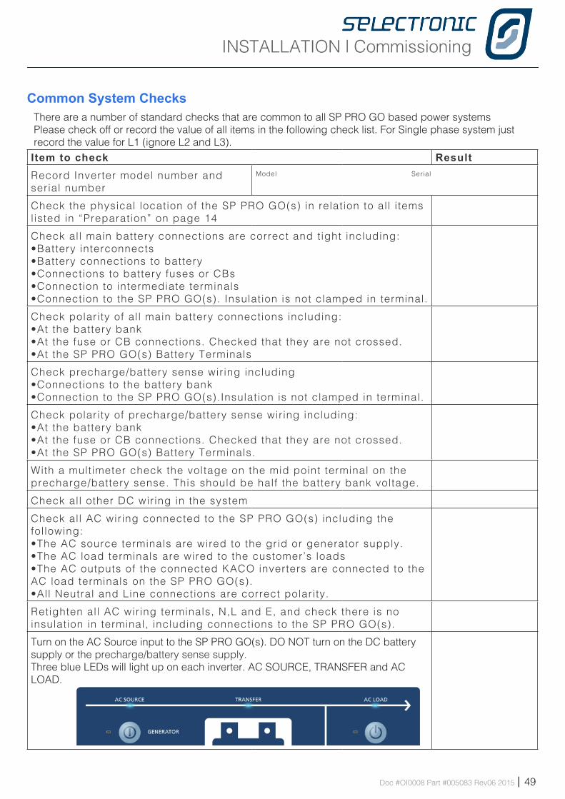
Common System ChecksThere are a number of standard checks that are common to all SP PRO GO based power systemsPlease check off or record the value of all items in the following check list. For Single phase system just record the value for L1 (ignore L2 and L3).Item to check ResultRecord Inverter model number and serial number
Model Serial
Check the physical location of the SP PRO GO(s) in relation to all i tems l isted in “Preparation” on page 14
Check all main battery connections are correct and tight including:•Battery interconnects•Battery connections to battery•Connections to battery fuses or CBs•Connection to intermediate terminals•Connection to the SP PRO GO(s). Insulation is not clamped in terminal.
Check polarity of al l main battery connections including:•At the battery bank•At the fuse or CB connections. Checked that they are not crossed.•At the SP PRO GO(s) Battery Terminals
Check precharge/battery sense wiring including•Connections to the battery bank•Connection to the SP PRO GO(s).Insulation is not clamped in terminal.
Check polarity of precharge/battery sense wiring including:•At the battery bank•At the fuse or CB connections. Checked that they are not crossed.•At the SP PRO GO(s) Battery Terminals.
With a multimeter check the voltage on the mid point terminal on the precharge/battery sense. This should be half the battery bank voltage.
Check all other DC wiring in the system
Check all AC wiring connected to the SP PRO GO(s) including the following:•The AC source terminals are wired to the grid or generator supply.•The AC load terminals are wired to the customer’s loads•The AC outputs of the connected KACO inverters are connected to the AC load terminals on the SP PRO GO(s).•All Neutral and Line connections are correct polarity.
Retighten all AC wiring terminals, N,L and E, and check there is no insulation in terminal, including connections to the SP PRO GO(s).
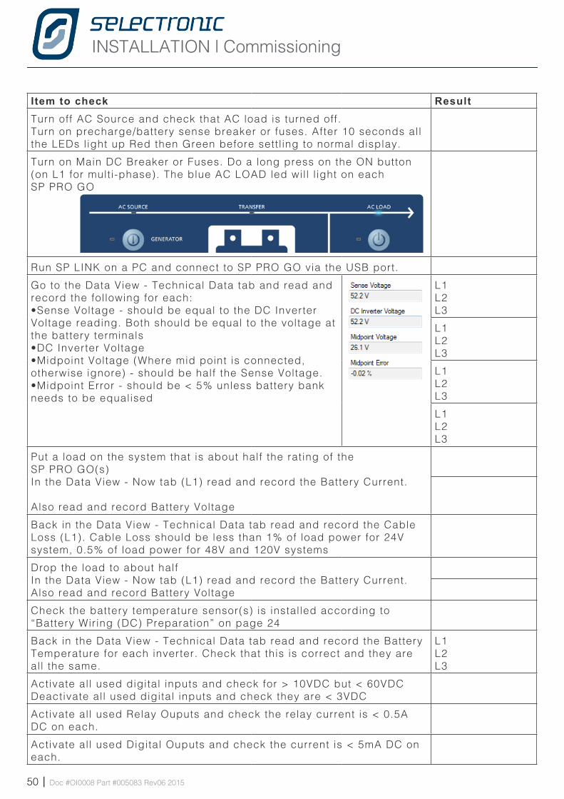
Turn on the AC Source input to the SP PRO GO(s). DO NOT turn on the DC battery supply or the precharge/battery sense supply. Three blue LEDs will light up on each inverter. AC SOURCE, TRANSFER and AC LOAD.
INSTALLATION | Commissioning
50 | Doc #OI0008 Part #005083 Rev06 2015
Item to check ResultTurn off AC Source and check that AC load is turned off.Turn on precharge/battery sense breaker or fuses. After 10 seconds all the LEDs l ight up Red then Green before settl ing to normal display.
Turn on Main DC Breaker or Fuses. Do a long press on the ON button (on L1 for multi-phase). The blue AC LOAD led wil l l ight on each SP PRO GO
Run SP LINK on a PC and connect to SP PRO GO via the USB port.
Go to the Data View - Technical Data tab and read and record the following for each:•Sense Voltage - should be equal to the DC Inverter Voltage reading. Both should be equal to the voltage at the battery terminals•DC Inverter Voltage •Midpoint Voltage (Where mid point is connected, otherwise ignore) - should be half the Sense Voltage.•Midpoint Error - should be < 5% unless battery bank needs to be equalised
L1L2L3
L1L2L3
L1L2L3
L1L2L3
Put a load on the system that is about half the rating of the SP PRO GO(s)In the Data View - Now tab (L1) read and record the Battery Current.
Also read and record Battery Voltage
Back in the Data View - Technical Data tab read and record the Cable Loss (L1). Cable Loss should be less than 1% of load power for 24V system, 0.5% of load power for 48V and 120V systems
Drop the load to about halfIn the Data View - Now tab (L1) read and record the Battery Current.Also read and record Battery Voltage
Check the battery temperature sensor(s) is installed according to “Battery Wiring (DC) Preparation” on page 24
Back in the Data View - Technical Data tab read and record the Battery Temperature for each inverter. Check that this is correct and they are all the same.
L1L2L3
Activate all used digital inputs and check for > 10VDC but < 60VDCDeactivate all used digital inputs and check they are < 3VDC
Activate all used Relay Ouputs and check the relay current is < 0.5A DC on each.
Activate all used Digital Ouputs and check the current is < 5mA DC on each.
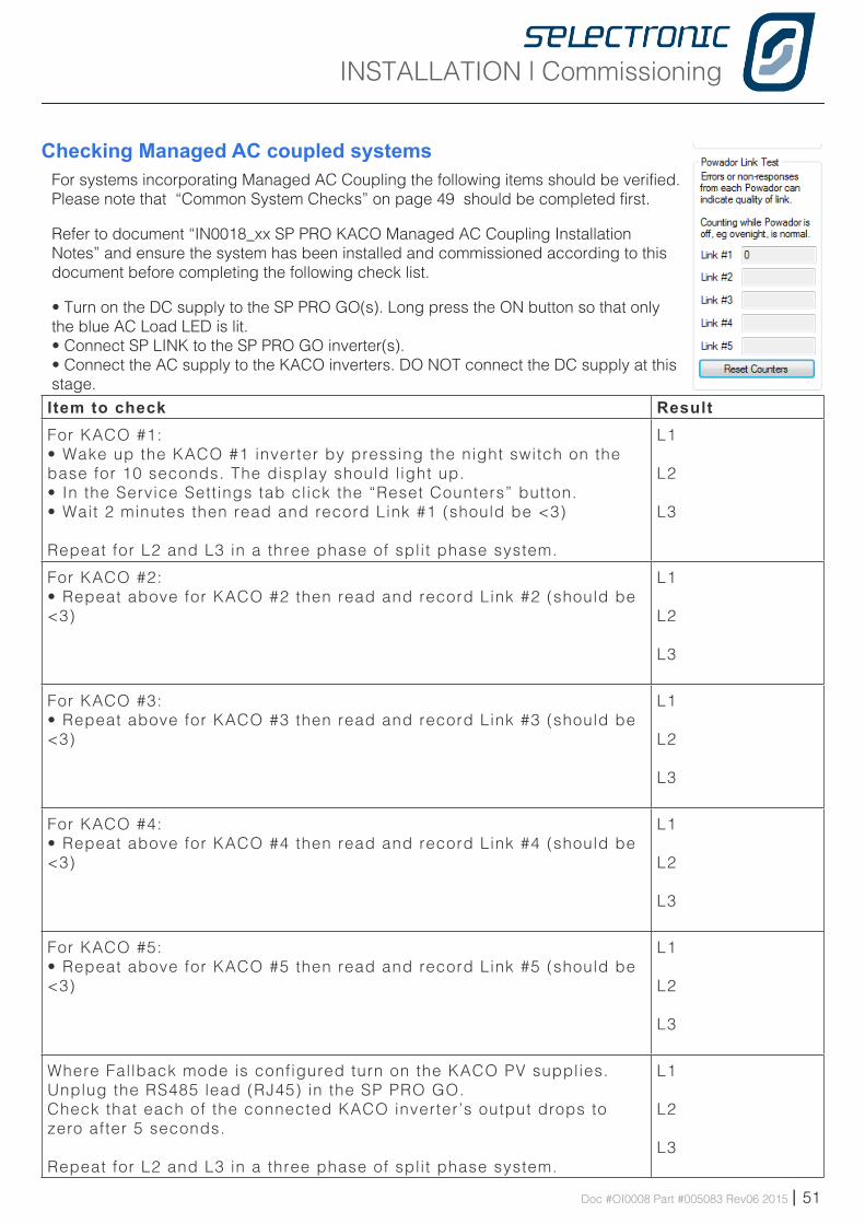
INSTALLATION | Commissioning
Doc #OI0008 Part #005083 Rev06 2015 | 51
Checking Managed AC coupled systemsFor systems incorporating Managed AC Coupling the following items should be verified. Please note that “Common System Checks” on page 49 should be completed first.
Refer to document “IN0018_xx SP PRO KACO Managed AC Coupling Installation Notes” and ensure the system has been installed and commissioned according to this document before completing the following check list.
• Turn on the DC supply to the SP PRO GO(s). Long press the ON button so that only the blue AC Load LED is lit.• Connect SP LINK to the SP PRO GO inverter(s). • Connect the AC supply to the KACO inverters. DO NOT connect the DC supply at this stage.Item to check ResultFor KACO #1: • Wake up the KACO #1 inverter by pressing the night switch on the base for 10 seconds. The display should l ight up. • In the Service Settings tab click the “Reset Counters” button.• Wait 2 minutes then read and record Link #1 (should be <3)
Repeat for L2 and L3 in a three phase of split phase system.
L1
L2
L3
For KACO #2: • Repeat above for KACO #2 then read and record Link #2 (should be <3)
L1
L2
L3
For KACO #3: • Repeat above for KACO #3 then read and record Link #3 (should be <3)
L1
L2
L3
For KACO #4: • Repeat above for KACO #4 then read and record Link #4 (should be <3)
L1
L2
L3
For KACO #5: • Repeat above for KACO #5 then read and record Link #5 (should be <3)
L1
L2
L3
Where Fallback mode is configured turn on the KACO PV supplies.Unplug the RS485 lead (RJ45) in the SP PRO GO.Check that each of the connected KACO inverter’s output drops to zero after 5 seconds.
Repeat for L2 and L3 in a three phase of split phase system.
L1
L2
L3
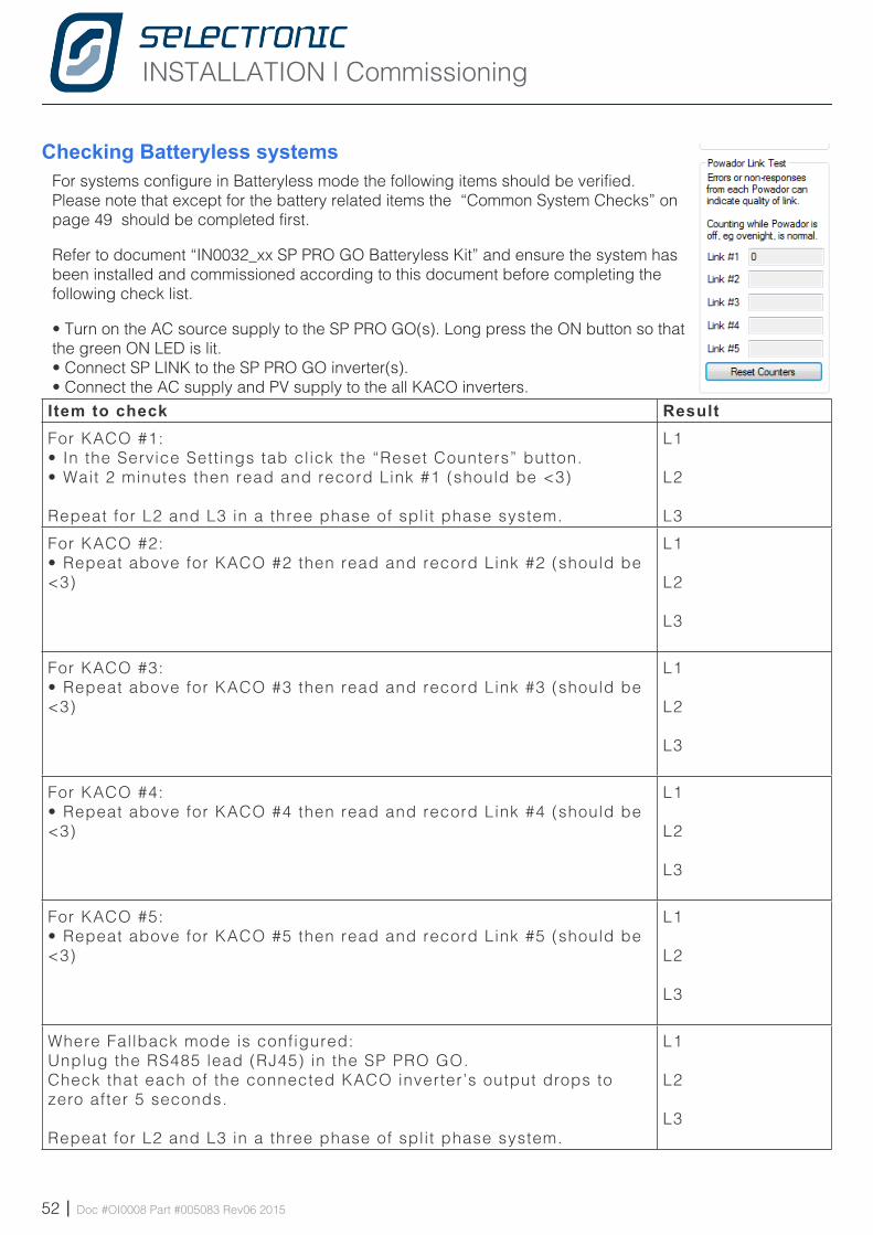
INSTALLATION | Commissioning
52 | Doc #OI0008 Part #005083 Rev06 2015
Checking Batteryless systemsFor systems configure in Batteryless mode the following items should be verified. Please note that except for the battery related items the “Common System Checks” on page 49 should be completed first.
Refer to document “IN0032_xx SP PRO GO Batteryless Kit” and ensure the system has been installed and commissioned according to this document before completing the following check list.
• Turn on the AC source supply to the SP PRO GO(s). Long press the ON button so that the green ON LED is lit.• Connect SP LINK to the SP PRO GO inverter(s). • Connect the AC supply and PV supply to the all KACO inverters.Item to check ResultFor KACO #1: • In the Service Settings tab click the “Reset Counters” button.• Wait 2 minutes then read and record Link #1 (should be <3)
Repeat for L2 and L3 in a three phase of split phase system.
L1
L2
L3
For KACO #2: • Repeat above for KACO #2 then read and record Link #2 (should be <3)
L1
L2
L3
For KACO #3: • Repeat above for KACO #3 then read and record Link #3 (should be <3)
L1
L2
L3
For KACO #4: • Repeat above for KACO #4 then read and record Link #4 (should be <3)
L1
L2
L3
For KACO #5: • Repeat above for KACO #5 then read and record Link #5 (should be <3)
L1
L2
L3
Where Fallback mode is configured:Unplug the RS485 lead (RJ45) in the SP PRO GO.Check that each of the connected KACO inverter’s output drops to zero after 5 seconds.
Repeat for L2 and L3 in a three phase of split phase system.
L1
L2
L3
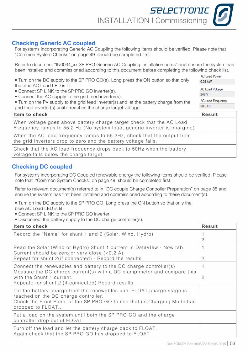
INSTALLATION | Commissioning
Doc #OI0008 Part #005083 Rev06 2015 | 53
Checking Generic AC coupled For systems incorporating Generic AC Coupling the following items should be verified. Please note that “Common System Checks” on page 49 should be completed first.
Refer to document “IN0034_xx SP PRO Generic AC Coupling installation notes” and ensure the system has been installed and commissioned according to this document before completing the following check list.
• Turn on the DC supply to the SP PRO GO(s). Long press the ON button so that only the blue AC Load LED is lit.• Connect SP LINK to the SP PRO GO inverter(s).• Connect the AC supply to the grid feed inverter(s).• Turn on the PV supply to the grid feed inverter(s) and let the battery charge from the grid feed inverter(s) until it reaches the charge target voltage.Item to check ResultWhen voltage goes above battery charge target check that the AC Load Frequency ramps to 55.2 Hz (No system load, generic inverter is charging)
When the AC load frequency ramps to 55.2Hz, check that the output from the grid inverters drop to zero and the battery voltage falls.
Check that the AC load frequency drops back to 50Hz when the battery voltage falls below the charge target.
Checking DC coupled For systems incorporating DC Coupled renewable energy the following items should be verified. Please note that “Common System Checks” on page 49 should be completed first.
Refer to relevant document(s) referred to in “DC couple Charge Controller Preparation” on page 35 and ensure the system has first been installed and commissioned according to these document(s).
• Turn on the DC supply to the SP PRO GO. Long press the ON button so that only the blue AC Load LED is lit.• Connect SP LINK to the SP PRO GO inverter.• Disconnect the battery supply to the DC charge controller(s).Item to check ResultRecord the “Name” for shunt 1 and 2 (Solar, Wind, Hydro)
12
Read the Solar (Wind or Hydro) Shunt 1 current in DataVIew - Now tab. Current should be zero or very close (<0.2 A).Repeat for shunt 2(if connected) - Record the results
1
2
Connect the renewables and battery to the DC charge controller(s) Measure the DC charge current(s) with a DC clamp meter and compare this with the Shunt 1 current. Repeate for shunt 2 (if connected) Record results.
1
2
Let the battery charge from the renewables unti l FLOAT charge stage is reached on the DC charge controller.Check the Front Panel of the SP PRO GO to see that its Charging Mode has dropped to FLOAT..
Put a load on the system unti l both the SP PRO GO and the charge controller drop out of FLOAT.
Turn off the load and let the battery charge back to FLOAT. Again check that the SP PRO GO has dropped to FLOAT
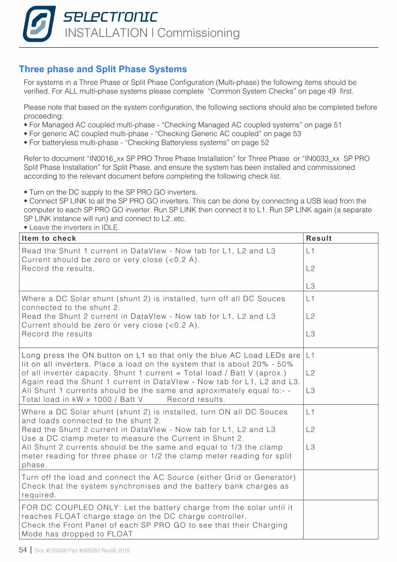
INSTALLATION | Commissioning
54 | Doc #OI0008 Part #005083 Rev06 2015
Three phase and Split Phase Systems For systems in a Three Phase or Split Phase Configuration (Multi-phase) the following items should be verified. For ALL multi-phase systems please complete “Common System Checks” on page 49 first.
Please note that based on the system configuration, the following sections should also be completed before proceeding:• For Managed AC coupled multi-phase - “Checking Managed AC coupled systems” on page 51• For generic AC coupled multi-phase - “Checking Generic AC coupled” on page 53• For batteryless multi-phase - “Checking Batteryless systems” on page 52
Refer to document “IN0016_xx SP PRO Three Phase Installation” for Three Phase or “IN0033_xx SP PRO Split Phase Installation” for Split Phase, and ensure the system has been installed and commissioned according to the relevant document before completing the following check list.
• Turn on the DC supply to the SP PRO GO inverters. • Connect SP LINK to all the SP PRO GO inverters. This can be done by connecting a USB lead from the computer to each SP PRO GO inverter. Run SP LINK then connect it to L1. Run SP LINK again (a separate SP LINK instance will run) and connect to L2..etc.• Leave the inverters in IDLE.Item to check ResultRead the Shunt 1 current in DataVIew - Now tab for L1, L2 and L3 Current should be zero or very close (<0.2 A).Record the results.
L1
L2
L3
Where a DC Solar shunt (shunt 2) is installed, turn off al l DC Souces connected to the shunt 2.Read the Shunt 2 current in DataVIew - Now tab for L1, L2 and L3 Current should be zero or very close (<0.2 A).Record the results
L1
L2
L3
Long press the ON button on L1 so that only the blue AC Load LEDs are l i t on all inverters. Place a load on the system that is about 20% - 50% of all inverter capacity. Shunt 1 current = Total load / Batt V (aprox.)Again read the Shunt 1 current in DataVIew - Now tab for L1, L2 and L3. All Shunt 1 currents should be the same and aproximately equal to:- -Total load in kW x 1000 / Batt V Record results.
L1
L2
L3
Where a DC Solar shunt (shunt 2) is installed, turn ON all DC Souces and loads connected to the shunt 2.Read the Shunt 2 current in DataVIew - Now tab for L1, L2 and L3 Use a DC clamp meter to measure the Current in Shunt 2.All Shunt 2 currents should be the same and equal to 1/3 the clamp meter reading for three phase or 1/2 the clamp meter reading for split phase.
L1
L2
L3
Turn off the load and connect the AC Source (either Grid or Generator)Check that the system synchronises and the battery bank charges as required.
FOR DC COUPLED ONLY: Let the battery charge from the solar unti l i t reaches FLOAT charge stage on the DC charge controller.Check the Front Panel of each SP PRO GO to see that their Charging Mode has dropped to FLOAT
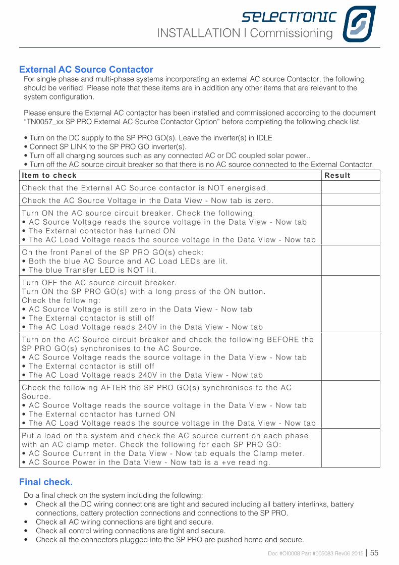
INSTALLATION | Commissioning
Doc #OI0008 Part #005083 Rev06 2015 | 55
External AC Source Contactor For single phase and multi-phase systems incorporating an external AC source Contactor, the following should be verified. Please note that these items are in addition any other items that are relevant to the system configuration.
Please ensure the External AC contactor has been installed and commissioned according to the document “TN0057_xx SP PRO External AC Source Contactor Option” before completing the following check list.
• Turn on the DC supply to the SP PRO GO(s). Leave the inverter(s) in IDLE• Connect SP LINK to the SP PRO GO inverter(s).• Turn off all charging sources such as any connected AC or DC coupled solar power..• Turn off the AC source circuit breaker so that there is no AC source connected to the External Contactor. Item to check ResultCheck that the External AC Source contactor is NOT energised.
Check the AC Source Voltage in the Data View - Now tab is zero.
Turn ON the AC source circuit breaker. Check the following:• AC Source Voltage reads the source voltage in the Data View - Now tab• The External contactor has turned ON • The AC Load Voltage reads the source voltage in the Data View - Now tab
On the front Panel of the SP PRO GO(s) check:• Both the blue AC Source and AC Load LEDs are l i t .• The blue Transfer LED is NOT lit.
Turn OFF the AC source circuit breaker.Turn ON the SP PRO GO(s) with a long press of the ON button.Check the following: • AC Source Voltage is sti l l zero in the Data View - Now tab • The External contactor is sti l l off • The AC Load Voltage reads 240V in the Data View - Now tab
Turn on the AC Source circuit breaker and check the following BEFORE the SP PRO GO(s) synchronises to the AC Source.• AC Source Voltage reads the source voltage in the Data View - Now tab• The External contactor is sti l l off • The AC Load Voltage reads 240V in the Data View - Now tab
Check the following AFTER the SP PRO GO(s) synchronises to the AC Source.• AC Source Voltage reads the source voltage in the Data View - Now tab• The External contactor has turned ON • The AC Load Voltage reads the source voltage in the Data View - Now tab
Put a load on the system and check the AC source current on each phase with an AC clamp meter. Check the following for each SP PRO GO:• AC Source Current in the Data View - Now tab equals the Clamp meter.• AC Source Power in the Data View - Now tab is a +ve reading.
Final check.Do a final check on the system including the following:• Check all the DC wiring connections are tight and secured including all battery interlinks, battery
connections, battery protection connections and connections to the SP PRO.• Check all AC wiring connections are tight and secure.• Check all control wiring connections are tight and secure.• Check all the connectors plugged into the SP PRO are pushed home and secure.
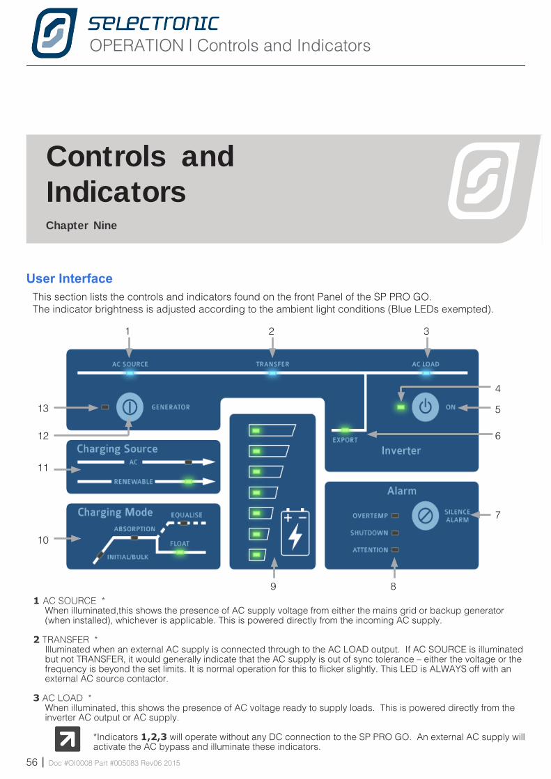
OPERATION | Controls and Indicators
56 | Doc #OI0008 Part #005083 Rev06 2015
Chapte r Nine
1 2 3
4
5
6
7
89
10
11
12
13
User InterfaceThis section lists the controls and indicators found on the front Panel of the SP PRO GO. The indicator brightness is adjusted according to the ambient light conditions (Blue LEDs exempted).
Cont ro ls and Ind ica to rs
1 AC SOURCE *When illuminated,this shows the presence of AC supply voltage from either the mains grid or backup generator (when installed), whichever is applicable. This is powered directly from the incoming AC supply.
2 TRANSFER *Illuminated when an external AC supply is connected through to the AC LOAD output. If AC SOURCE is illuminated but not TRANSFER, it would generally indicate that the AC supply is out of sync tolerance – either the voltage or the frequency is beyond the set limits. It is normal operation for this to flicker slightly. This LED is ALWAYS off with an external AC source contactor.
3 AC LOAD *When illuminated, this shows the presence of AC voltage ready to supply loads. This is powered directly from the inverter AC output or AC supply.
*Indicators 1,2,3 will operate without any DC connection to the SP PRO GO. An external AC supply will activate the AC bypass and illuminate these indicators.
OPERATION

OPERATION | Controls and Indicators
Doc #OI0008 Part #005083 Rev06 2015 | 57
4 OUTPUT MODE STATUSOff SP PRO GO Battery supply disconnected. AC bypass only. Slow flashing Yellow SP PRO GO is Idle (off) - Monitoring and logging but no inverter AC output.Steady Green The SP PRO GO is On.Slow Flashing Green SP PRO GO Econo mode is active and is sensing load conditions. Fast Flashing Green SP PRO GO is preparing to start.Steady Red Indicates that a Fault has been detected and no inverter output is possible.Flashing Red Indicates an open circuit or poor battery connection and no inverter output is possible.
5 ON BUTTON A LONG PRESS (>1 second) - turns the SP PRO GO On. Another long press SP PRO GO reverts to Idle.A SHORT PRESS (<1 second) - activates Econo mode (Not available in 120 VDC models)
6 ExPORTIndicates that the SP PRO GO is feeding power to the grid: On,exporting to the grid and suppling AC Load; Flashing, supplying the AC Load only, no export to grid.
7 SILENCE ALARM BUTTONTurns off the audible alarm for this instance only. Alarm will resound with a new alarm condition.
8 ALARM INDICATORS OVERTEMP
Yellow SP PRO GO is approaching an over temperature conditionRed SP PRO GO has shutdown due to an over temperature condition
SHUTDOWN Yellow SP PRO GO is approaching a shutdown conditionRed SP PRO GO has shutdown
ATTENTION Off NormalYellow Attention Required, Fan Service RequestFlashing Yellow Either Clean Fan, Fan Fault or Capacitor Bank Service RequestRed Immediate Attention requiredFlashing RED Unit Fault
See Attention Required in SP LINK Data View - Now section to determine specific reason for the attention indicator.
9 BATTERY “FUEL” GAUGE These indicate the battery State of Charge (SoC). When the battery SoC is equal to the Shutdown SoC (in Configuration Settings - Inverter tab) then only the bottom LED is green. At 100% SoC all LEDs are green.
Top Indicator Flashing RED Instant Hi DC Voltage Shutdown. Battery or battery wiring faultBottom Indicator Yellow Low Battery. Battery needs chargingBottom Indicator Red Low Battery Shutdown. Inverter has shut down due to flat batteryBottom Indicator Flashing RED Instant Low DC Voltage Shutdown. Battery or battery wiring fault.All Indicators flashing RED Inverter in emergency Low DC Shutdown Override (See SP LINK Manual)
10 CHARGING MODEThe Charging Mode panel indicates the present charging state. See “Battery Charging Operation” on page 60.
11 CHARGING SOURCEAC - On. Power from the AC Source input supply is charging battery bank (Grid or generator)Renewable - On Power from any monitored renewable energy supply is charging battery bank
12 BACKUP GENERATOR BUTTON & EQUALISE REQUEST A short press Start or stop the backup generator (where installed)..Two long presses Set or cancel an Equalise charge request. EQUALISE Indicator will flash. Next time charger reaches FLOAT an EQUALISE charge will be performed.
13 BACKUP GENERATOR STATUSOff No backup generator activityFlashing Green Generator is in the process of starting Steady Green Generator has started and is runningFlashing Yellow Generator is not available for auto startFlashing Red There is a generator fault
NOTE: Button 12 and LED 13 are not active when a backup generator is not installed.
OPERATION | SP PRO GO Operation
58 | Doc #OI0008 Part #005083 Rev06 2015
SP PRO GO Operat ionChapte r Ten
The following section describes in detail the operation of the SP PRO GO. A good understanding of the operation of the SP PRO GO and its parameters will enable configuration of the SP PRO GO to meet the system design requirements.
The SP PRO GO Battery management continuously monitors the system operation. This monitoring allows the SP PRO GO to ensure the batteries are correctly charged to maximise system reliability. The monitoring includes any input from renewable sources (AC or DC Coupled) and any loads directly connected to the battery bank.
The SP PRO GO uses a five stage temperature compensated battery charging system. This system gives a high degree of flexibility so it can charge the multitude of battery types available.
Also incorporated are a number of “time of day” and “day of week” schedules. These schedules can be set to meet the cheapest electricity rates or reduce high load demands from the grid.
WARNING: This equipment must be used in accordance with the instructions in this manual and any other related documents. If this equipment is used in a manner not specified by the manufacturer as contained in this manual and other operational documents and Instructions, then the protection provided by the equipment may be impaired.
DO NOT remove any covers. Their are no operator accessible parts within the SP PRO GO.
OPERATION | SP PRO GO Operation
Doc #OI0008 Part #005083 Rev06 2015 | 59
Battery ManagementPlease refer to the battery manufacturer’s documentation for recommendations regarding settings for the particular battery. Inappropriate settings may have a detrimental affect on the battery life and performance.
The SP PRO GO provides comprehensive battery management settings and control to allow a charge regime to achieve optimal battery life.
SP PRO GO battery management features include:• State of Charge monitoring and control.• Battery terminal voltage monitoring (Battery Sense / pre-charge) and control.• Charging initiated by battery state of charge and/or battery voltage.• Five stage charge cycle: Initial, Bulk, Absorption, Float (short term and long term) and Equalise.• Shutdown on low battery voltage, battery state of charge, or both.• Two stage Battery Temperature compensation of charging voltage based on battery temperature.
The SP PRO GO may be configured to use the Grid power or to automatically start a backup generator (with Grid Fail - Generator Backup Option) when a battery charge cycle is required during a prolonged grid outage.
Battery State of Charge (SoC) monitoring and controlFor SoC control to function correctly all DC battery currents, other than the inverter current, must be monitored on either or both of the two current shunt inputs to the SP PRO GO. No current shunt is required to read the SP PROs current or any AC Coupled supply as this is read internally. The resultant battery current is monitored to track the battery SoC which is expressed as a percentage of the battery size set in the SP PRO GO (Battery Capacity).
The accuracy of the battery SoC is limited by a number of factors including the charge and discharge efficiency of the battery bank. To improve the accuracy of the battery SoC calculation, the SP PRO GO employs an adaptive algorithm to constantly update a “charge efficiency index” which is used during recharge.
When a Grid Fail, Generator Backup option is installed in the system, the state of charge is used to automatically start the generator during a grid outage. The generator will then supply the load while any excess available generator capacity will charge the batteries.
When the grid is available, the state of charge along with time of day and load demand is used to vary the priority and direct the renewable energy to either power the AC load, recharge the battery bank and/or export to the grid. This allows for the maximum use of the renewable energy (such as PV solar) whilst taking advantage of variable electricity tariffs
Battery Voltage monitoring and controlThe SP PRO GO measures the battery voltage both at the inverter and also directly at the battery bank using the Battery Sense / pre-charge wiring (if installed). Sensing the actual battery terminal voltage (using Battery Sense / pre-charge wiring) compensates for the effect of cable losses which, irrespective of charge or discharge currents, keeps the battery terminal voltage within set limits.
Battery voltage is used to protect the system by shutting the unit down should the battery voltage go above or below set limits. The shutdown limits must be set to higher than the maximum charge voltage. For the low voltage shutdown limits the SP PRO GO employs different levels depending on system load. The system will always attempt to reconnect to the grid or start the backup generator (when installed) before shutting the inverter down due to low battery voltage or SoC.
OPERATION | SP PRO GO Operation
60 | Doc #OI0008 Part #005083 Rev06 2015
Battery Charging OperationThe SP PRO GO charging system manages all charging sources in the power system giving priority as appropriate to the renewable energy sources. This ensures that the renewable sources are used in the most cost effective manner.
The SP PRO GO continuously monitors all charging sources to recharge the battery in a five-stage cycle. Each stage or Charging Mode is controlled by voltage, current and time settings. These settings are fully configurable using SP LINK and should not require changing after initial installation, unless some aspect of the battery installation changes.
Each voltage setting is battery temperature compensated. The set values displayed do not change. See Battery Temperature for details.
BATTERY CHARGING MODE.
Read the following with reference to the Battery Charging Cycle graph on the following page.
INITIALThe SP PRO GO charges at the initial charging current until the battery voltage rises to the initial charge voltage, then holds this voltage for a set time before starting the Bulk stage. When in the Initial charge phase, the Initial/Bulk indicator will flash.
BULKThe SP PRO GO charges at the bulk charging current until the battery voltage rises to the bulk charge voltage, then holds this voltage for a set length of time, before starting the Absorption stage. In Bulk charge mode, the Initial/Bulk indicator will be steady ON.
ABSORBIn the Absorption charge phase the SP PRO GO will charge at the absorb charge current until the absorb charge voltage is reached. Once this voltage is reached, the SP PRO GO will carefully monitor the rate of change of the charge current as set in the Absorb-Float transition setting. When the Absorb-Float transition setting is met, the charge cycle will switch to Float and terminate an auto start backup generator if connected. If an Equalise charge is pending, the Equalise charge cycle will now be performed. The Absorption indicator will be steady on when in the Absorption phase.
FLOATThe SP PRO GO holds the battery voltage at the Float level and will provide up to the float current to maintain the float voltage. The SP PRO GO will remain in this charge state until battery voltage falls below the Initial Return level. If the SP PRO GO is still connected to an AC Source after 24 hours of Float, the charger will transition to the Long Term Float voltage. Long Term float voltage will allow batteries to sit at a lower voltage level indefinitely, reducing battery losses.
EQUALISEPeriodically, the SP PRO GO performs an equalise charge in which the battery is held at a higher voltage for a period set in the EQUALISE window. This will help ensure all cells within the battery bank have an equal amount of charge. The equalise indicator will be steady on when in equalise mode and will flash when an equalise is pending, that is the charger will perform an equalise after float stage is next reached.
Note on Battery Charging: Lead acid batteries (such as GEL, Flooded, AGM, VRLA) normally start to take less charge when they reach 80% State Of Charge (SoC) and above. It is normal to see the Charge Current reducing and excess PV solar being exported or PV controllers (including KACO managed AC coupled solar) power limiting when the batteries reach 80% SoC.
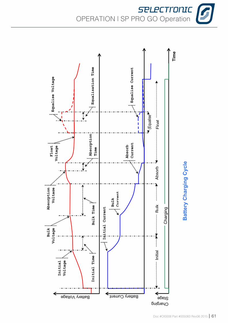
OPERATION | SP PRO GO Operation
Doc #OI0008 Part #005083 Rev06 2015 | 61
Battery Voltage
Bulk
Voltage
Absorption
Voltage
Float
Voltage
Equalise Voltage
Bulk
Ab
sorb
Fl
oat
Battery Current
Initial Current
Absorb
Current
Tim
e
Equalise Current
(Equ
alise
)
Cha
rgin
g Bulk
Current
Initial
Voltage In
itial
Initial Time
Absorption
Time
Bulk Time
Charging Stage
Equalisation Time
Bat
tery
Cha
rgin
g C
ycle
OPERATION | SP PRO GO Operation
62 | Doc #OI0008 Part #005083 Rev06 2015
Battery Temperature CompensationThe SP PRO GO monitors the battery temperature via the sensor provided. The supplied battery temperature sensor must be mounted in thermal contact with the centre of the side of the battery. If the sensor is not in thermal contact with the battery bank the batteries will not be correctly charged. Check battery temperature is reading correctly in the Temperature Control section of Technical Data in SP LINK.
The charge voltage set points are compensated by battery temperature. The default compensation applied is -5.5 mV/°C/cell with zero compensation at 25°C.
e.g. Initial Voltage = 55.2, Battery Temperature = 26°C, No. Battery Cells = 24.Compensated Charge voltage = 55.2 + ((26 - 25) x -0.0055 x 24) = 55.07Absorption Voltage = 57.6, Battery Temperature = 6°C, No. Battery Cells = 24.Compensated Charge voltage = 57.6 + ((6 - 25) x -0.0055 x 24) = 60.11
During all charge stages, the compensated charge voltage will not exceed Max Voltage Limit.Compensation improves battery performance by preventing over or undercharging the battery and protects against battery overheating.
The charge current is also limited by battery temperature. Battery temperatures above 45°C cause the battery charger to reduce the charge current limit point. This will help also help protect the battery from overheating.
The temperature compensated charge voltage target and charge current target at any point in time can be viewed in SP LINK under the Data View -Technical Data tab, “Target Charge Voltage” and “Target Charge Current”.
OPERATION | SP PRO GO Operation
Doc #OI0008 Part #005083 Rev06 2015 | 63
Renewable ManagementSOLAR HYBRID -GRID AVAILABLEIn Solar Hybrid, the renewable energy can be directed to power the AC load, recharge the battery bank and/or export to the grid. The direction and priority of the energy flow can be varied dependant on the time of day, battery SoC or load demands allowing the maximum use of the renewable energy (such as PV solar) whilst taking advantage of variable electricity tariffs.
SOLAR HYBRID -GRID OUTAGEWhen the grid fails the SP PRO GO feeds renewable power to the AC load, and any excess is stored in the battery for later use. If the battery is fully charged and all loads are being supplied, the renewable power is backed off (DC coupling or managed AC coupling) or disconnected (Generic AC coupling) to prevent overcharging of the batteries
Backup Generator Controls (with option)The SP PRO GO may be configured to automatically control a backup generator in a Solar Hybrid power system using the optional “Grid fail - Gen backup” module. During a grid outage the generator will be automatically started by the SP PRO GO as required to supply the load and charge the battery bank.
As part of the installation, the SP PRO GO settings are configured to automatically run the generator during a grid outage to:
• Limit the depth of battery discharge, for maximum battery life.• Deliver energy efficiently by supplying sustained large loads direct from the generator.• Load the generator to the highest possible level while running, to efficiently convert fuel to electricity.• Limit generator starting frequency, which would reduce its life and increase maintenance.• Avoid noise by only starting the generator late at night for heavy loads or a deeply discharged battery.
For full details on backup generator controls please see the documentation supplied with the optional Grid Fail - Generator Backup option.
Inverter External AlarmThe SP PRO GO provides an alarm output which can be wired to an external alarm buzzer or light. A shutdown alarm is indicated by a continuous ON condition and an alert alarm is indicated by a slow intermittent ON/OFF condition. The SP PRO GO is in alarm state when shutdown or idle. The alarm relay is active in the normal or no alarm state condition (i.e. use the NC relay contacts to run an alarm buzzer or indicator). Alert conditions can be prevented from raising the alarm, via SP LINK.
SERVICE | Service and Maintenance
64 | Doc #OI0008 Part #005083 Rev06 2015
Serv ice and Ma in tenanceChapte r E leven
Multiple Sources of SupplyHazardous voltages and energy is generated by and are fed into the SP PRO GO by external wiring from multiple sources and may be stored in capacitors after switched off. Ensure the isolation of all energy sources. including AC source isolator, battery main isolator, battery precharge isolator and all renewable energy sources including solar, wind and hydro before carrying out maintenance on the SP PRO GO. A time of at least 5 minutes must elapse AFTER the disconnection of the battery main isolator and the battery precharge isolator before any trained technical staff gain internal access to the SP PRO GO
Cleaning the Fan and Fan filter1. Ensure fan is stationary2. Remove the four retaining screws that hold the fan filter in place.3. Clean the filter mesh with a soft brush or similar implement.4. Check to see if there are any foreign matter that could impede the fan operation.5. Replace filter and tighten the four retaining screws.
All other maintenance on the SP PRO GO should be performed by a Selectronic Accredited Integrator.
Above the fan filter is a safety grill. Do not remove this grill – fast moving fan blades can cause injury
Monitoring the Operation of the SP PRO GOInstalling SP LINK software onto a PC also installs SP LINK Auto QuickView. This program is a shortened version or SP LINK designed to automatically connect to and display information about the SP PRO GO.
Using this program allows the following items to be monitored on a regular basis:
• BATTERY VOLTAGE (QuickView Tab)- this should NEVER be below the nominal system voltage - 24 V, 48 V or 120 V
• BATTERY SoC% (QuickView Tab) - a high average figure will maintain good battery life• The AVERAGE DAILY ENERGY SUPPLIED to the load (Data View - Today Tab) is within design
parameter.• PERFORMANCE DATA EVENTS. - Download performance data in the Performance Data Menu.• SERVICE REQUIRED - Check the Attention Required box in the Data View - Now Tab. Right click this to
open the SP LINK manual which contains a list of messages and the actions required.
SERVICE
SERVICE | Service and Maintenance
Doc #OI0008 Part #005083 Rev06 2015 | 65
System ShutdownThe Installer / integrator will provide detailed Shutdown and Restart instructions specific to the installation.
Installer Maintenance of SP PRO GOOther than ensuring all AC and DC connections are always tight, there are only three areas that may require maintenance.• FAN ALERT – This can be checked in the “Now” tab of the “Data View” section. A fan alert generally
indicates that the fan is stationary when it should be running. This will mean that either the fan needs replacement or that a foreign body is stuck in the fan. Also see “Multiple Sources of Supply” on page 64
• FAN LIFE is recorded in the “Technical Data” section of the “Data View” tab. Fan life is expressed in the percentage of fan life used i.e. The figure starts at 0% and rises the longer the fan runs. As fan life is projected to be in excess of 40,000 hours quite a high percentage of fan life can be used before replacement is necessary.
• CAPACITOR LIFE is measured on both halves of the power module and is expressed, as before, in percentage of life used. The power module should be replaced when capacitor life, in either half, reaches 95%.
There are no user serviceable or replaceable parts within the SP PRO GO. Any maintenance, other than fan filter cleaning, should be performed by a Selectronic Authorised Integrator.
System MaintenanceA Selectronic Accredited Integrator will provide advise on the maintenance that is required for the balance of the system components.
Battery Maintenance and replacementBatteries are a hazardous part of the power system. Servicing and replacement of batteries must be performed by suitably qualified personnel knowledgeable about batteries and the required precautions.
When replacing batteries in the system ensure that they are replace with the same type and number of batteries as the original system. When removing of replacing batteries please ensure that the battery manufacturer’s recommendations and instructions are followed..
CAUTION: Do not dispose of batteries in a fire. The batteries may explode.CAUTION: Do not open or damage batteries. Released electrolyte is harmful to theskin and eyes. It may be toxic.CAUTION: A battery can present a risk of electrical shock and high short-circuit
current. The following precautions should be observed when working on batteries:• Remove watches, rings, or other metal objects.• Use tools with insulated handles.• Wear rubber gloves and boots.• Do not lay tools or metal parts on top of batteries.• Disconnect charging source prior to connecting or disconnecting battery terminals.• Determine if battery is inadvertently grounded. If inadvertently grounded, remove source from ground.
Contact with any part of a grounded battery can result in electrical shock. The likelihood of such shock can be reduced if such grounds are removed during installation and maintenance
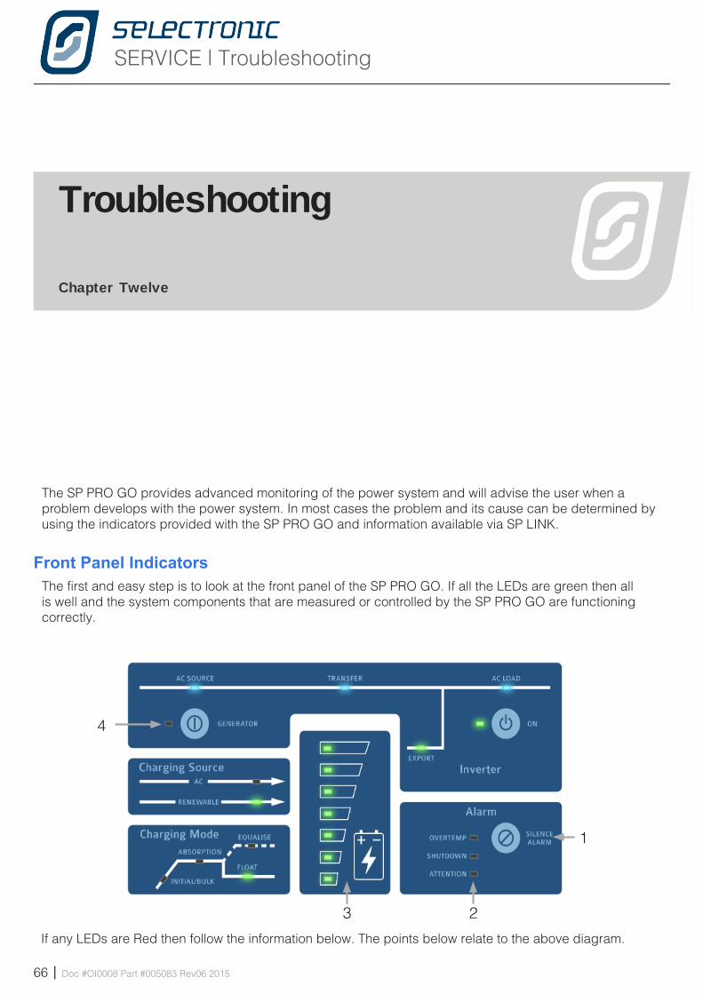
SERVICE | Troubleshooting
66 | Doc #OI0008 Part #005083 Rev06 2015
Troubleshooting
Chapte r Twe lve
The SP PRO GO provides advanced monitoring of the power system and will advise the user when a problem develops with the power system. In most cases the problem and its cause can be determined by using the indicators provided with the SP PRO GO and information available via SP LINK.
Front Panel IndicatorsThe first and easy step is to look at the front panel of the SP PRO GO. If all the LEDs are green then all is well and the system components that are measured or controlled by the SP PRO GO are functioning correctly.
1
23
4
If any LEDs are Red then follow the information below. The points below relate to the above diagram.
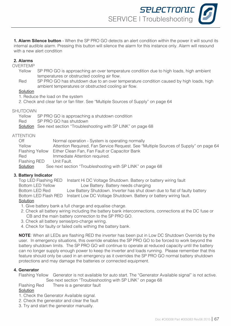
SERVICE | Troubleshooting
Doc #OI0008 Part #005083 Rev06 2015 | 67
1. Alarm Silence button - When the SP PRO GO detects an alert condition within the power it will sound its internal audible alarm. Pressing this button will silence the alarm for this instance only. Alarm will resound with a new alert condition
2. AlarmsOVERTEMP
Yellow SP PRO GO is approaching an over temperature condition due to high loads, high ambient temperatures or obstructed cooling air flow.
Red SP PRO GO has shutdown due to an over temperature condition caused by high loads, high ambient temperatures or obstructed cooling air flow.
Solution 1. Reduce the load on the system 2. Check and clear fan or fan filter. See “Multiple Sources of Supply” on page 64
SHUTDOWN Yellow SP PRO GO is approaching a shutdown conditionRed SP PRO GO has shutdown Solution See next section “Troubleshooting with SP LINK” on page 68
ATTENTION Off Normal operation - System is operating normallyYellow Attention Required, Fan Service Request. See “Multiple Sources of Supply” on page 64 Flashing Yellow Either Clean Fan, Fan Fault or Capacitor BankRed Immediate Attention required.Flashing RED Unit Fault. Solution See next section “Troubleshooting with SP LINK” on page 68
3. Battery IndicatorTop LED Flashing RED Instant Hi DC Voltage Shutdown. Battery or battery wiring faultBottom LED Yellow Low Battery. Battery needs chargingBottom LED Red Low Battery Shutdown. Inverter has shut down due to flat of faulty batteryBottom LED Flash RED Instant Low DC Voltage Shutdown. Battery or battery wiring fault.Solution1. Give battery bank a full charge and equalise charge. 2. Check all battery wiring including the battery bank interconnections, connections at the DC fuse or
CB and the main battery connection to the SP PRO GO.3. Check all battery sense/pro-charge wiring.4. Check for faulty or failed cells withing the battery bank.
NOTE: When all LEDs are flashing RED the inverter has been put in Low DC Shutdown Override by the user. In emergency situations, this override enables the SP PRO GO to be forced to work beyond the battery shutdown limits. The SP PRO GO will continue to operate at reduced capacity until the battery can no longer supply enough power to keep the inverter and loads running. Please remember that this feature should only be used in an emergency as it overrides the SP PRO GO normal battery shutdown protections and may damage the batteries or connected equipment.
4. GeneratorFlashing Yellow Generator is not available for auto start. The “Generator Available signal” is not active.
See next section “Troubleshooting with SP LINK” on page 68Flashing Red There is a generator faultSolution1. Check the Generator Available signal. 2. Check the generator and clear the fault3. Try and start the generator manually.
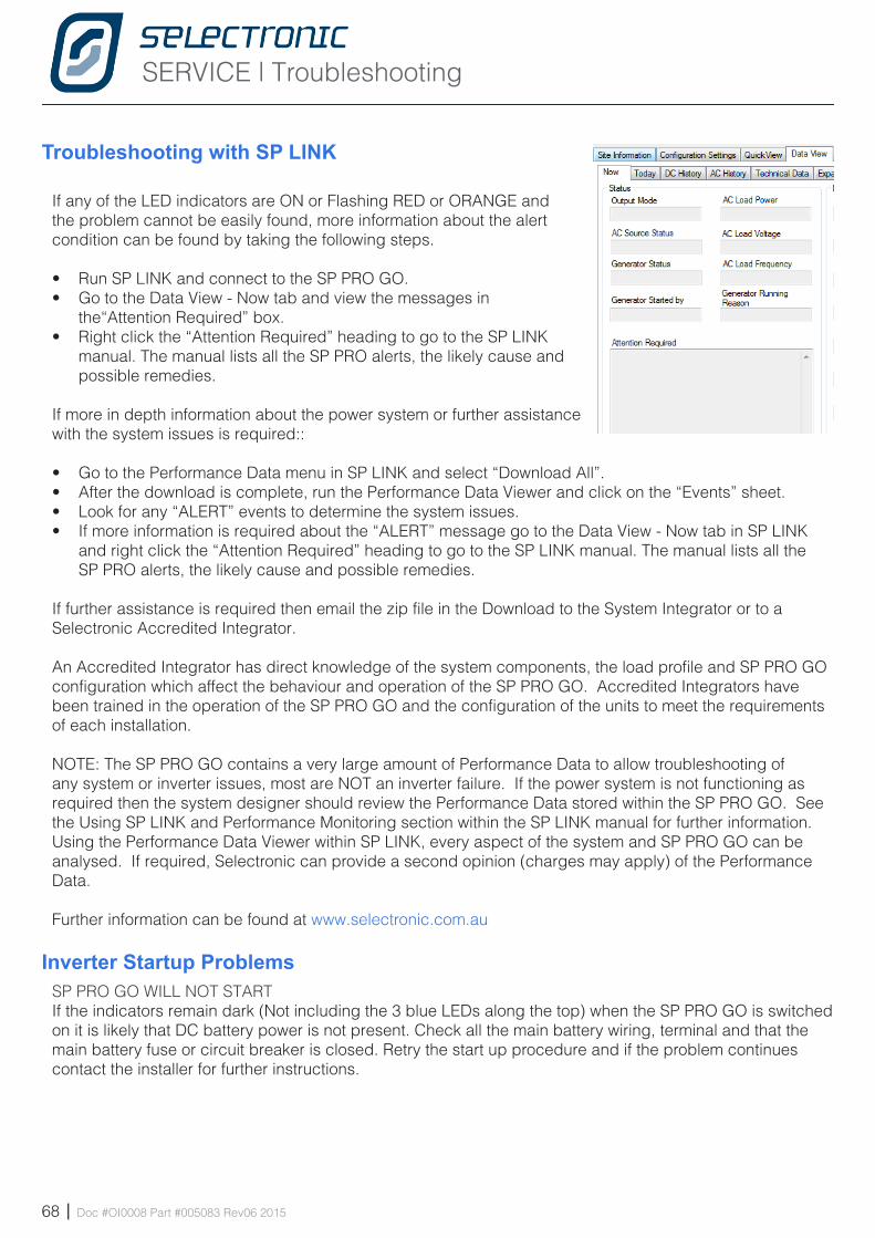
SERVICE | Troubleshooting
68 | Doc #OI0008 Part #005083 Rev06 2015
Troubleshooting with SP LINK
If any of the LED indicators are ON or Flashing RED or ORANGE and the problem cannot be easily found, more information about the alert condition can be found by taking the following steps.
• Run SP LINK and connect to the SP PRO GO.• Go to the Data View - Now tab and view the messages in
the“Attention Required” box.• Right click the “Attention Required” heading to go to the SP LINK
manual. The manual lists all the SP PRO alerts, the likely cause and possible remedies.
If more in depth information about the power system or further assistance with the system issues is required::
• Go to the Performance Data menu in SP LINK and select “Download All”. • After the download is complete, run the Performance Data Viewer and click on the “Events” sheet.• Look for any “ALERT” events to determine the system issues.• If more information is required about the “ALERT” message go to the Data View - Now tab in SP LINK
and right click the “Attention Required” heading to go to the SP LINK manual. The manual lists all the SP PRO alerts, the likely cause and possible remedies.
If further assistance is required then email the zip file in the Download to the System Integrator or to a Selectronic Accredited Integrator.
An Accredited Integrator has direct knowledge of the system components, the load profile and SP PRO GO configuration which affect the behaviour and operation of the SP PRO GO. Accredited Integrators have been trained in the operation of the SP PRO GO and the configuration of the units to meet the requirements of each installation.
NOTE: The SP PRO GO contains a very large amount of Performance Data to allow troubleshooting of any system or inverter issues, most are NOT an inverter failure. If the power system is not functioning as required then the system designer should review the Performance Data stored within the SP PRO GO. See the Using SP LINK and Performance Monitoring section within the SP LINK manual for further information. Using the Performance Data Viewer within SP LINK, every aspect of the system and SP PRO GO can be analysed. If required, Selectronic can provide a second opinion (charges may apply) of the Performance Data.
Further information can be found at www.selectronic.com.au
Inverter Startup ProblemsSP PRO GO WILL NOT STARTIf the indicators remain dark (Not including the 3 blue LEDs along the top) when the SP PRO GO is switched on it is likely that DC battery power is not present. Check all the main battery wiring, terminal and that the main battery fuse or circuit breaker is closed. Retry the start up procedure and if the problem continues contact the installer for further instructions.
SERVICE | Troubleshooting
Doc #OI0008 Part #005083 Rev06 2015 | 69
AC Power ProblemsIf the power fluctuates, lights go bright or dim but don’t go out.• Check the SP PRO GO front panel indicators and Performance data for information on the cause.• The SP PRO GO output may be varying due to starting very heavy loads. Check the output voltage
reading (AC Load Voltage) via SP LINK.
If the power goes off for short periods (1 second to a few minutes)• Check the SP PRO GO front panel indicators and Performance Data for information on the cause.• The SP PRO GO may be in Power Save mode and the load is too small to detect. In this mode the
SP PRO GO pulses the output until a load is detected. Check the Econo Power Level in SP LINK.• The SP PRO GO may be shutting down due to overload or low DC voltage and periodically attempting
restarts. If the SP PRO GO is shutting down switch off any heavy loads that may be causing the shut down.
If the power goes off for longer periods (10 minutes to many hours)• Check the SP PRO GO front panel indicators and Performance Data for information on the cause.• Check the Attention Required window in the Now tab in Data View section of SP LINK to see if a fault is
indicated and contact the supplier for further instructions.
Battery ProblemsBatteries are very dangerous. Please read the safety information provided by the battery supplier.
Battery does not charge properly• Check that the battery charging requirements are correctly set up in the SP PRO GO.• Check that the solar regulator is correctly set up.• Check all cables and connections to the batteries.
If the solar does not appear to be doing much, the solar regulator may be set too low. Check indicators and DC History in SP LINK.
If the battery is not operating correctly:• Physically inspect the battery and check for loose connections. Monitor the battery voltage as heavy
loads supplied by the SP PRO GO are turned on and off.• Check the voltage on each battery making up the battery bank to see if there are cells not fully charged
or not accepting charge. Measure voltages on each cell/battery at different times in the charge discharge cycle. Just after charge has started say after 10 minutes, in mid charge, just before end of charge, ten minutes after discharge starts, mid discharge and just before recharge starts.
Grid related ProblemsGRID AVAILABLE BUT POWER IS LOST• The likely cause is the SP PRO GO has disconnected from the grid due to high voltage or frequency, leaving the
site to operate from the limited battery storage. To resolve, widen the “Sync Tolerance” parameters or contact the electricity supplier.
DC COUPLED SOLAR SYSTEM THAT DOESN’T ExPORT AS ExPECTED• The likely cause is the Solar Controller (external device to the SP PRO GO) is restricting the flow of power from the
PV array. To resolve, make sure the Solar Controller float charging set point is ~ 1 V higher than the SP PRO GO Float stage set point. and the charge stages are linked. See “DC couple Charge Controller Preparation” on page 35
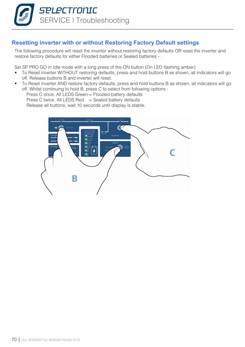
SERVICE | Troubleshooting
70 | Doc #OI0008 Part #005083 Rev06 2015
Resetting inverter with or without Restoring Factory Default settingsThe following procedure will reset the inverter without restoring factory defaults OR reset the inverter and restore factory defaults for either Flooded batteries or Sealed batteries - .
Set SP PRO GO in Idle mode with a long press of the ON button (On LED flashing amber)• To Reset inverter WITHOUT restoring defaults, press and hold buttons B as shown, all indicators will go
off. Release buttons B and inverter will reset. • To Reset inverter AND restore factory defaults, press and hold buttons B as shown, all indicators will go
off. Whilst continuing to hold B, press C to select from following options - Press C once. All LEDS Green = Flooded battery defaults Press C twice. All LEDS Red = Sealed battery defaults Release all buttons, wait 10 seconds until display is stable.

Blank Page
Doc #OI0008 Part #005083 Rev06 2015 | 71
SERVICE | Appendix A - Specifications
72 | Doc #OI0008 Part #005083 Rev06 2015
Append ix A Spec i f i ca t i onsAppend ix
C-tick Australia
Product Specifications
Note: Selectronic reserve the right to change specifications without notice.All ratings are at 25°C and nominal battery voltage unless otherwise stated. The product is specified to a maximum altitude of 2000 metres.
Standards ComplianceIEC 62109-1 Ed. 1.0 Safety of power converters for use in photovoltaic power systems - Part 1 General requirements
IEC 62109-2 Ed. 1.0 Safety of power converters for use in photovoltaic power systems - Part 2 Particular requirements for inverters
AS62040.1.1-2003 Uninterruptible power systems (UPS) - General and safety requirements for UPS used in operator access areas
AS/NZS 61000-6-3:2007 Electromagnetic Compatibility (EMC) - Part 6-3: Generic Standards - Emission Standard For Residential, Commercial And Light-industrial Environments
AS/NZS 61000-6-4:2007 Electromagnetic Compatibility (EMC) - Part 6-4: Generic Standards - Emission Standard For Industry
AS 4777.2-2005 Grid connection of energy systems via inverters - Inverter requirements
AS 4777.3-2005 Grid connection of energy systems via inverters - Grid protection requirements
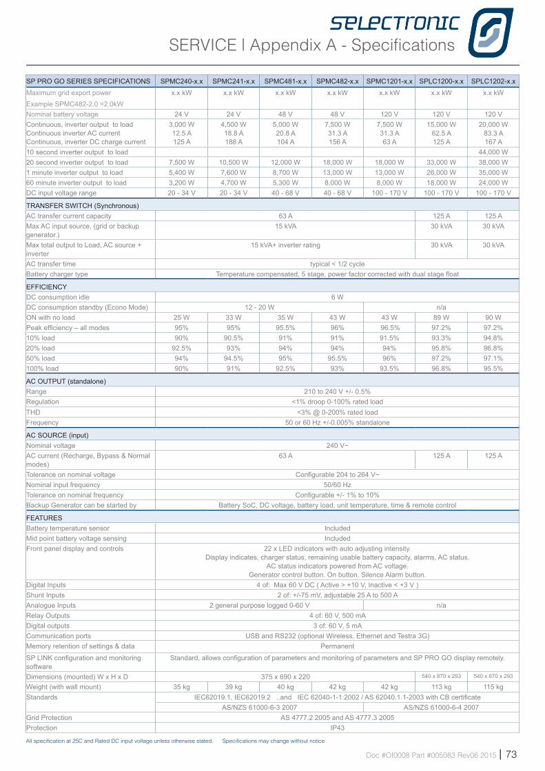
SERVICE | Appendix A - Specifications
Doc #OI0008 Part #005083 Rev06 2015 | 73
SP PRO GO SERIES SPECIFICATIONS SPMC240-x.x SPMC241-x.x SPMC481-x.x SPMC482-x.x SPMC1201-x.x SPLC1200-x.x SPLC1202-x.x
Maximum grid export powerExample SPMC482-2.0 =2.0kW
x.x kW x.x kW x.x kW x.x kW x.x kW x.x kW x.x kW
Nominal battery voltage 24 V 24 V 48 V 48 V 120 V 120 V 120 VContinuous, inverter output to load Continuous inverter AC current Continuous, inverter DC charge current
3,000 W 12.5 A 125 A
4,500 W 18.8 A 188 A
5,000 W 20.8 A 104 A
7,500 W 31.3 A 156 A
7,500 W 31.3 A 63 A
15,000 W 62.5 A 125 A
20,000 W 83.3 A 167 A
10 second inverter output to load 44,000 W20 second inverter output to load 7,500 W 10,500 W 12,000 W 18,000 W 18,000 W 33,000 W 38,000 W1 minute inverter output to load 5,400 W 7,600 W 8,700 W 13,000 W 13,000 W 26,000 W 35,000 W60 minute inverter output to load 3,200 W 4,700 W 5,300 W 8,000 W 8,000 W 18,000 W 24,000 WDC input voltage range 20 - 34 V 20 - 34 V 40 - 68 V 40 - 68 V 100 - 170 V 100 - 170 V 100 - 170 V
TRANSFER SWITCH (Synchronous)AC transfer current capacity 63 A 125 A 125 AMax AC input source, (grid or backup generator.)
15 kVA 30 kVA 30 kVA
Max total output to Load, AC source + inverter
15 kVA+ inverter rating 30 kVA 30 kVA
AC transfer time typical < 1/2 cycleBattery charger type Temperature compensated, 5 stage, power factor corrected with dual stage float
EFFICIENCyDC consumption idle 6 WDC consumption standby (Econo Mode) 12 - 20 W n/aON with no load 25 W 33 W 35 W 43 W 43 W 89 W 90 WPeak efficiency – all modes 95% 95% 95.5% 96% 96.5% 97.2% 97.2%10% load 90% 90.5% 91% 91% 91.5% 93.3% 94.8%20% load 92.5% 93% 94% 94% 94% 95.8% 96.8%50% load 94% 94.5% 95% 95.5% 96% 97.2% 97.1%100% load 90% 91% 92.5% 93% 93.5% 96.8% 95.5%
AC OUTPUT (standalone)Range 210 to 240 V +/- 0.5%Regulation <1% droop 0-100% rated loadTHD <3% @ 0-200% rated loadFrequency 50 or 60 Hz +/-0.005% standalone
AC SOURCE (input) Nominal voltage 240 V~AC current (Recharge, Bypass & Normal modes)
63 A 125 A 125 A
Tolerance on nominal voltage Configurable 204 to 264 V~ Nominal input frequency 50/60 Hz Tolerance on nominal frequency Configurable +/- 1% to 10%Backup Generator can be started by Battery SoC, DC voltage, battery load, unit temperature, time & remote control
FEATURESBattery temperature sensor IncludedMid point battery voltage sensing IncludedFront panel display and controls 22 x LED indicators with auto adjusting intensity.
Display indicates, charger status, remaining usable battery capacity, alarms, AC status. AC status indicators powered from AC voltage.
Generator control button. On button. Silence Alarm button.Digital Inputs 4 of: Max 60 V DC ( Active > +10 V, Inactive < +3 V )Shunt Inputs 2 of: +/-75 mV, adjustable 25 A to 500 A Analogue Inputs 2 general purpose logged 0-60 V n/aRelay Outputs 4 of: 60 V, 500 mADigital outputs 3 of: 60 V, 5 mACommunication ports USB and RS232 (optional Wireless, Ethernet and Testra 3G)Memory retention of settings & data Permanent
SP LINK configuration and monitoring software
Standard, allows configuration of parameters and monitoring of parameters and SP PRO GO display remotely.
Dimensions (mounted) W x H x D 375 x 690 x 220 540 x 870 x 293 540 x 870 x 293
Weight (with wall mount) 35 kg 39 kg 40 kg 42 kg 42 kg 113 kg 115 kgStandards IEC62019.1, IEC62019.2 ..and IEC 62040-1-1:2002 / AS 62040.1.1-2003 with CB certificate
AS/NZS 61000-6-3 2007 AS/NZS 61000-6-4 2007Grid Protection AS 4777.2 2005 and AS 4777.3 2005Protection IP43
All specification at 25C and Rated DC input voltage unless otherwise stated. Specifications may change without notice
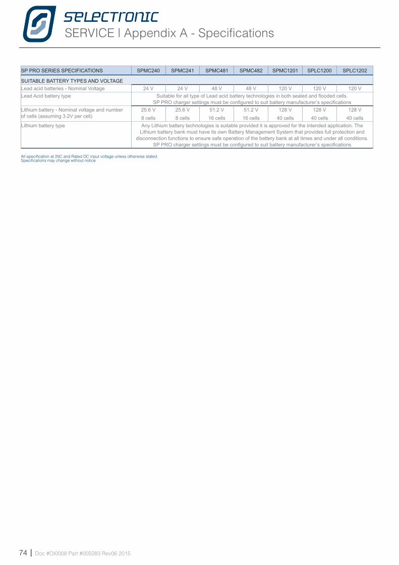
SERVICE | Appendix A - Specifications
74 | Doc #OI0008 Part #005083 Rev06 2015
SP PRO SERIES SPECIFICATIONS SPMC240 SPMC241 SPMC481 SPMC482 SPMC1201 SPLC1200 SPLC1202
SUITABLE BATTERy TyPES AND VOLTAGELead acid batteries - Nominal Voltage 24 V 24 V 48 V 48 V 120 V 120 V 120 VLead Acid battery type Suitable for all type of Lead acid battery technologies in both sealed and flooded cells.
SP PRO charger settings must be configured to suit battery manufacturer’s specificationsLithium battery - Nominal voltage and number of cells (assuming 3.2V per cell)
25.6 V8 cells
25.6 V8 cells
51.2 V16 cells
51.2 V16 cells
128 V40 cells
128 V40 cells
128 V40 cells
Lithium battery type Any Lithium battery technologies is suitable provided it is approved for the intended application. The Lithium battery bank must have its own Battery Management System that provides full protection and
disconnection functions to ensure safe operation of the battery bank at all times and under all conditions. SP PRO charger settings must be configured to suit battery manufacturer’s specifications
All specification at 25C and Rated DC input voltage unless otherwise stated. Specifications may change without notice

Blank Page
Doc #OI0008 Part #005083 Rev06 2015 | 75

Selectronic Australia Pty Ltd© 2015
Suite 5, 20 Fletcher RdChirnside Park VIC 3116AustraliaPh +61 3 9727 6600Fax +61 3 9727 6601
www.selectronic.com.au Doc #OI0008 Part #005083 Rev06 2015