Boost Your Managed Services and Profits by Adding Disaster Recovery to any Acronis Installation
IN0051 Revision 01 (005293)– 1 of 23 POWER PERFORMANCE PASSION
SP PRO Interactive Inverter Charger
Installation Note
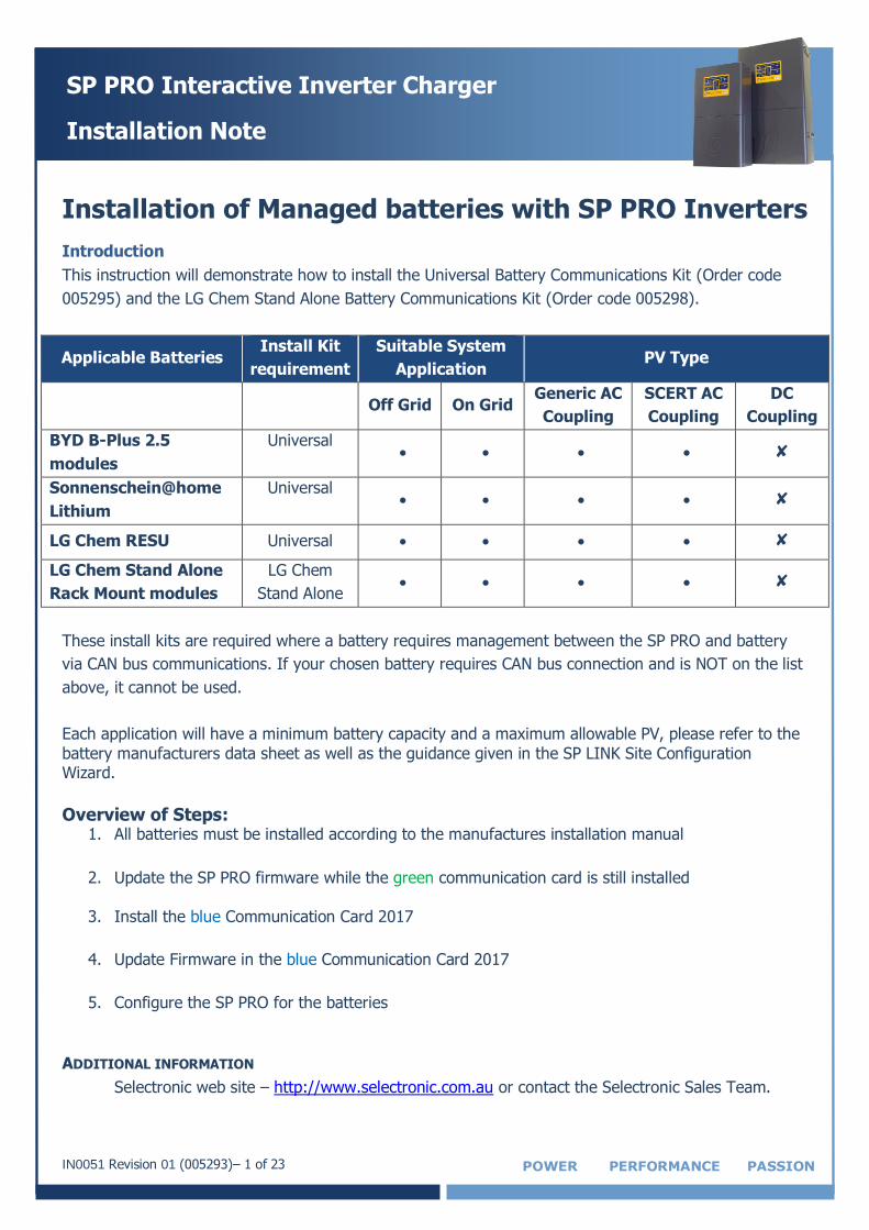
Installation of Managed batteries with SP PRO Inverters
Introduction
This instruction will demonstrate how to install the Universal Battery Communications Kit (Order code
005295) and the LG Chem Stand Alone Battery Communications Kit (Order code 005298).
Applicable Batteries Install Kit
requirement
Suitable System
Application PV Type
Off Grid On Grid Generic AC
Coupling
SCERT AC
Coupling
DC
Coupling
BYD B-Plus 2.5
modules
Universal ✘
Sonnenschein@home
Lithium
Universal ✘
LG Chem RESU Universal ✘
LG Chem Stand Alone
Rack Mount modules
LG Chem
Stand Alone ✘
These install kits are required where a battery requires management between the SP PRO and battery
via CAN bus communications. If your chosen battery requires CAN bus connection and is NOT on the list
above, it cannot be used.
Each application will have a minimum battery capacity and a maximum allowable PV, please refer to the
battery manufacturers data sheet as well as the guidance given in the SP LINK Site Configuration Wizard.
Overview of Steps: 1. All batteries must be installed according to the manufactures installation manual
2. Update the SP PRO firmware while the green communication card is still installed
3. Install the blue Communication Card 2017
4. Update Firmware in the blue Communication Card 2017
5. Configure the SP PRO for the batteries
ADDITIONAL INFORMATION
Selectronic web site – http://www.selectronic.com.au or contact the Selectronic Sales Team.
IN0051 Revision 01 (005293)– 2 of 23 POWER PERFORMANCE PASSION
SP PRO Interactive Inverter Charger
Installation Note
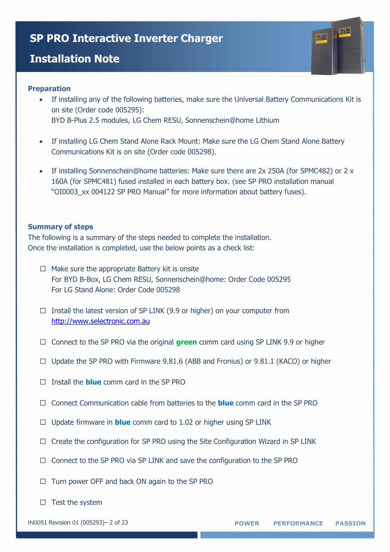
Preparation
If installing any of the following batteries, make sure the Universal Battery Communications Kit is
on site (Order code 005295):
BYD B-Plus 2.5 modules, LG Chem RESU, Sonnenschein@home Lithium
If installing LG Chem Stand Alone Rack Mount: Make sure the LG Chem Stand Alone Battery
Communications Kit is on site (Order code 005298).
If installing Sonnenschein@home batteries: Make sure there are 2x 250A (for SPMC482) or 2 x
160A (for SPMC481) fused installed in each battery box. (see SP PRO installation manual
“OI0003_xx 004122 SP PRO Manual” for more information about battery fuses).
Summary of steps
The following is a summary of the steps needed to complete the installation.
Once the installation is completed, use the below points as a check list:
Make sure the appropriate Battery kit is onsite
For BYD B-Box, LG Chem RESU, Sonnenschein@home: Order Code 005295
For LG Stand Alone: Order Code 005298
Install the latest version of SP LINK (9.9 or higher) on your computer from
http://www.selectronic.com.au
Connect to the SP PRO via the original green comm card using SP LINK 9.9 or higher
Update the SP PRO with Firmware 9.81.6 (ABB and Fronius) or 9.81.1 (KACO) or higher
Install the blue comm card in the SP PRO
Connect Communication cable from batteries to the blue comm card in the SP PRO
Update firmware in blue comm card to 1.02 or higher using SP LINK
Create the configuration for SP PRO using the Site Configuration Wizard in SP LINK
Connect to the SP PRO via SP LINK and save the configuration to the SP PRO
Turn power OFF and back ON again to the SP PRO
Test the system
IN0051 Revision 01 (005293)– 3 of 23 POWER PERFORMANCE PASSION
SP PRO Interactive Inverter Charger
Installation Note
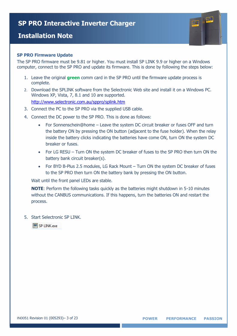
SP PRO Firmware Update
The SP PRO firmware must be 9.81 or higher. You must install SP LINK 9.9 or higher on a Windows computer, connect to the SP PRO and update its firmware. This is done by following the steps below:
1. Leave the original green comm card in the SP PRO until the firmware update process is
complete.
2. Download the SPLINK software from the Selectronic Web site and install it on a Windows PC. Windows XP, Vista, 7, 8.1 and 10 are supported.
http://www.selectronic.com.au/sppro/splink.htm
3. Connect the PC to the SP PRO via the supplied USB cable.
4. Connect the DC power to the SP PRO. This is done as follows:
For Sonnenschein@home – Leave the system DC circuit breaker or fuses OFF and turn
the battery ON by pressing the ON button (adjacent to the fuse holder). When the relay
inside the battery clicks indicating the batteries have come ON, turn ON the system DC
breaker or fuses.
For LG RESU – Turn ON the system DC breaker of fuses to the SP PRO then turn ON the
battery bank circuit breaker(s).
For BYD B-Plus 2.5 modules, LG Rack Mount – Turn ON the system DC breaker of fuses
to the SP PRO then turn ON the battery bank by pressing the ON button.
Wait until the front panel LEDs are stable.
NOTE: Perform the following tasks quickly as the batteries might shutdown in 5-10 minutes
without the CANBUS communications. If this happens, turn the batteries ON and restart the
process.
5. Start Selectronic SP LINK.
IN0051 Revision 01 (005293)– 4 of 23 POWER PERFORMANCE PASSION
SP PRO Interactive Inverter Charger
Installation Note
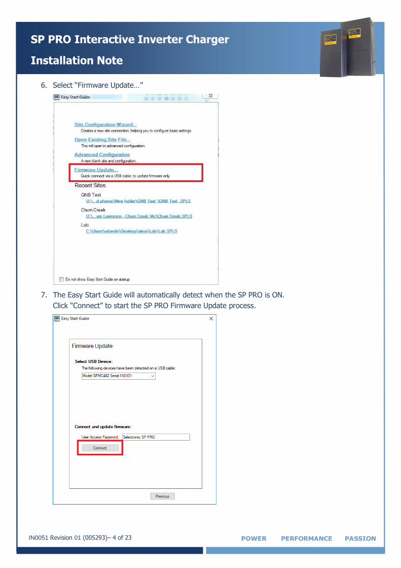
6. Select “Firmware Update…”
7. The Easy Start Guide will automatically detect when the SP PRO is ON.
Click “Connect” to start the SP PRO Firmware Update process.
IN0051 Revision 01 (005293)– 5 of 23 POWER PERFORMANCE PASSION
SP PRO Interactive Inverter Charger
Installation Note
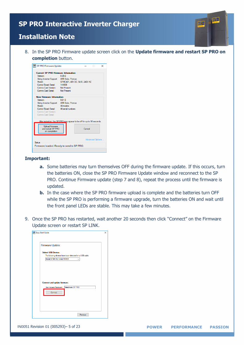
8. In the SP PRO Firmware update screen click on the Update firmware and restart SP PRO on
completion button.
Important:
a. Some batteries may turn themselves OFF during the firmware update. If this occurs, turn
the batteries ON, close the SP PRO Firmware Update window and reconnect to the SP
PRO. Continue Firmware update (step 7 and 8), repeat the process until the firmware is
updated.
b. In the case where the SP PRO firmware upload is complete and the batteries turn OFF
while the SP PRO is performing a firmware upgrade, turn the batteries ON and wait until
the front panel LEDs are stable. This may take a few minutes.
9. Once the SP PRO has restarted, wait another 20 seconds then click “Connect” on the Firmware
Update screen or restart SP LINK.
IN0051 Revision 01 (005293)– 6 of 23 POWER PERFORMANCE PASSION
SP PRO Interactive Inverter Charger
Installation Note
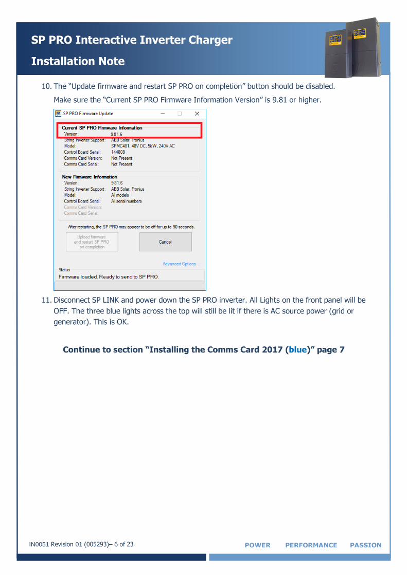
10. The “Update firmware and restart SP PRO on completion” button should be disabled.
Make sure the “Current SP PRO Firmware Information Version” is 9.81 or higher.
11. Disconnect SP LINK and power down the SP PRO inverter. All Lights on the front panel will be
OFF. The three blue lights across the top will still be lit if there is AC source power (grid or
generator). This is OK.
Continue to section “Installing the Comms Card 2017 (blue)” page 7
IN0051 Revision 01 (005293)– 7 of 23 POWER PERFORMANCE PASSION
SP PRO Interactive Inverter Charger
Installation Note
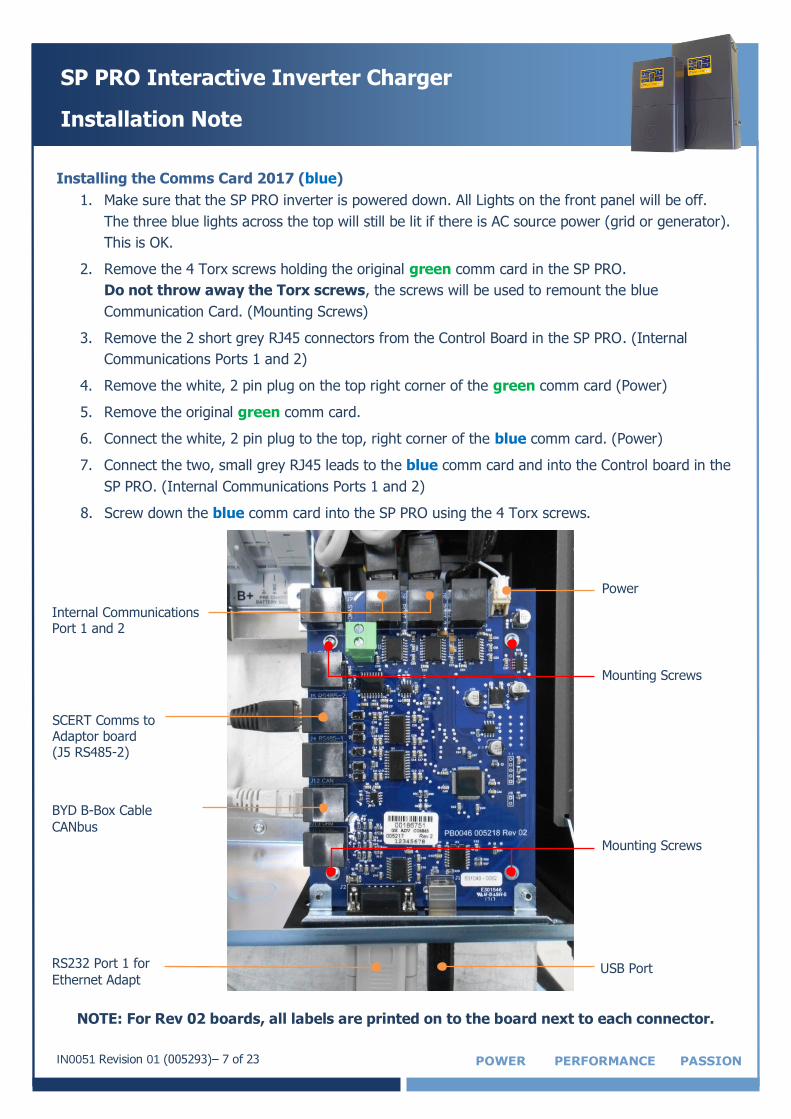
Installing the Comms Card 2017 (blue)
1. Make sure that the SP PRO inverter is powered down. All Lights on the front panel will be off.
The three blue lights across the top will still be lit if there is AC source power (grid or generator).
This is OK.
2. Remove the 4 Torx screws holding the original green comm card in the SP PRO.
Do not throw away the Torx screws, the screws will be used to remount the blue
Communication Card. (Mounting Screws)
3. Remove the 2 short grey RJ45 connectors from the Control Board in the SP PRO. (Internal
Communications Ports 1 and 2)
4. Remove the white, 2 pin plug on the top right corner of the green comm card (Power)
5. Remove the original green comm card.
6. Connect the white, 2 pin plug to the top, right corner of the blue comm card. (Power)
7. Connect the two, small grey RJ45 leads to the blue comm card and into the Control board in the
SP PRO. (Internal Communications Ports 1 and 2)
8. Screw down the blue comm card into the SP PRO using the 4 Torx screws.
NOTE: For Rev 02 boards, all labels are printed on to the board next to each connector.
Power
Internal Communications Port 1 and 2
USB Port
SCERT Comms to Adaptor board (J5 RS485-2)
BYD B-Box Cable
CANbus
RS232 Port 1 for
Ethernet Adapt
Mounting Screws
Mounting Screws
IN0051 Revision 01 (005293)– 8 of 23 POWER PERFORMANCE PASSION
SP PRO Interactive Inverter Charger
Installation Note
Communications Connection to SP PRO
The following communication connections must be completed for the appropriate battery type in order
for the system to operate with the SP PRO.
This section outlines the connection process of the communication line for the different battery options
compatible with the SP PRO inverter.
Section 1 for BYD B-Plus ONLY: Go to page 9
Communication connection for BYD B-Box
Section 2 for LG RESU (Single battery) ONLY: Go to page 10
Communication connection for LG RESU
Section 3 for LG RESU Plus (Dual battery) ONLY: Go to page 11
Communication connection for LG RESU Plus
Section 4 for LG Stand Alone ONLY: Go to page 12
Communication connection for LG Rack Mount
Section 5 for Sonnenschein@home Lithium ONLY: Go to page 13
Communication connection for Sonnenschein@home Lithium
IN0051 Revision 01 (005293)– 9 of 23 POWER PERFORMANCE PASSION
SP PRO Interactive Inverter Charger
Installation Note
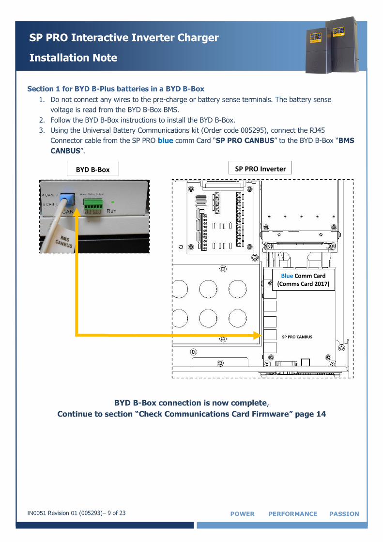
Section 1 for BYD B-Plus batteries in a BYD B-Box
1. Do not connect any wires to the pre-charge or battery sense terminals. The battery sense
voltage is read from the BYD B-Box BMS.
2. Follow the BYD B-Box instructions to install the BYD B-Box.
3. Using the Universal Battery Communications kit (Order code 005295), connect the RJ45
Connector cable from the SP PRO blue comm Card “SP PRO CANBUS” to the BYD B-Box “BMS
CANBUS”.
BYD B-Box connection is now complete,
Continue to section “Check Communications Card Firmware” page 14
SP PRO Inverter
Blue Comm Card (Comms Card 2017)
SP PRO CANBUS
BYD B-Box
IN0051 Revision 01 (005293)– 10 of 23 POWER PERFORMANCE PASSION
SP PRO Interactive Inverter Charger
Installation Note
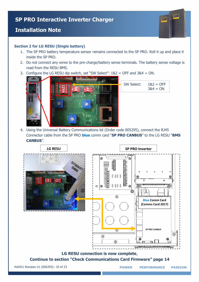
Section 2 for LG RESU (Single battery)
1. The SP PRO battery temperature sensor remains connected to the SP PRO. Roll it up and place it
inside the SP PRO.
2. Do not connect any wires to the pre-charge/battery sense terminals. The battery sense voltage is
read from the RESU BMS.
3. Configure the LG RESU dip switch, set “SW Select”: 1&2 = OFF and 3&4 = ON.
4. Using the Universal Battery Communications kit (Order code 005295), connect the RJ45
Connector cable from the SP PRO blue comm card “SP PRO CANBUS” to the LG RESU “BMS
CANBUS”.
LG RESU connection is now complete,
Continue to section “Check Communications Card Firmware” page 14
SW Select: 1&2 = OFF
3&4 = ON
SP PRO Inverter
Blue Comm Card (Comms Card 2017)
SP PRO CANBUS
LG RESU
IN0051 Revision 01 (005293)– 11 of 23 POWER PERFORMANCE PASSION
SP PRO Interactive Inverter Charger
Installation Note
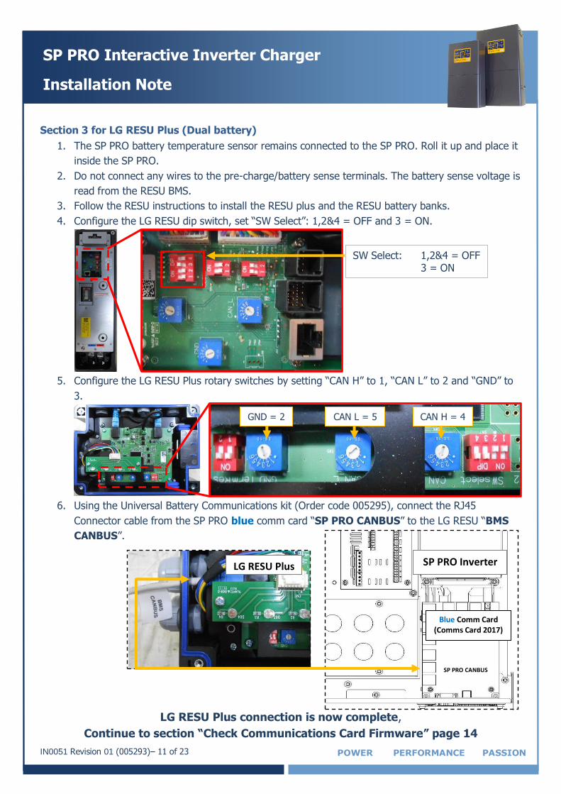
Section 3 for LG RESU Plus (Dual battery)
1. The SP PRO battery temperature sensor remains connected to the SP PRO. Roll it up and place it
inside the SP PRO.
2. Do not connect any wires to the pre-charge/battery sense terminals. The battery sense voltage is
read from the RESU BMS.
3. Follow the RESU instructions to install the RESU plus and the RESU battery banks.
4. Configure the LG RESU dip switch, set “SW Select”: 1,2&4 = OFF and 3 = ON.
5. Configure the LG RESU Plus rotary switches by setting “CAN H” to 1, “CAN L” to 2 and “GND” to
3.
6. Using the Universal Battery Communications kit (Order code 005295), connect the RJ45
Connector cable from the SP PRO blue comm card “SP PRO CANBUS” to the LG RESU “BMS
CANBUS”.
LG RESU Plus connection is now complete,
Continue to section “Check Communications Card Firmware” page 14
SW Select: 1,2&4 = OFF 3 = ON
GND = 2 CAN L = 5 CAN H = 4
SP PRO Inverter
Blue Comm Card (Comms Card 2017)
SP PRO CANBUS
LG RESU Plus
IN0051 Revision 01 (005293)– 12 of 23 POWER PERFORMANCE PASSION
SP PRO Interactive Inverter Charger
Installation Note
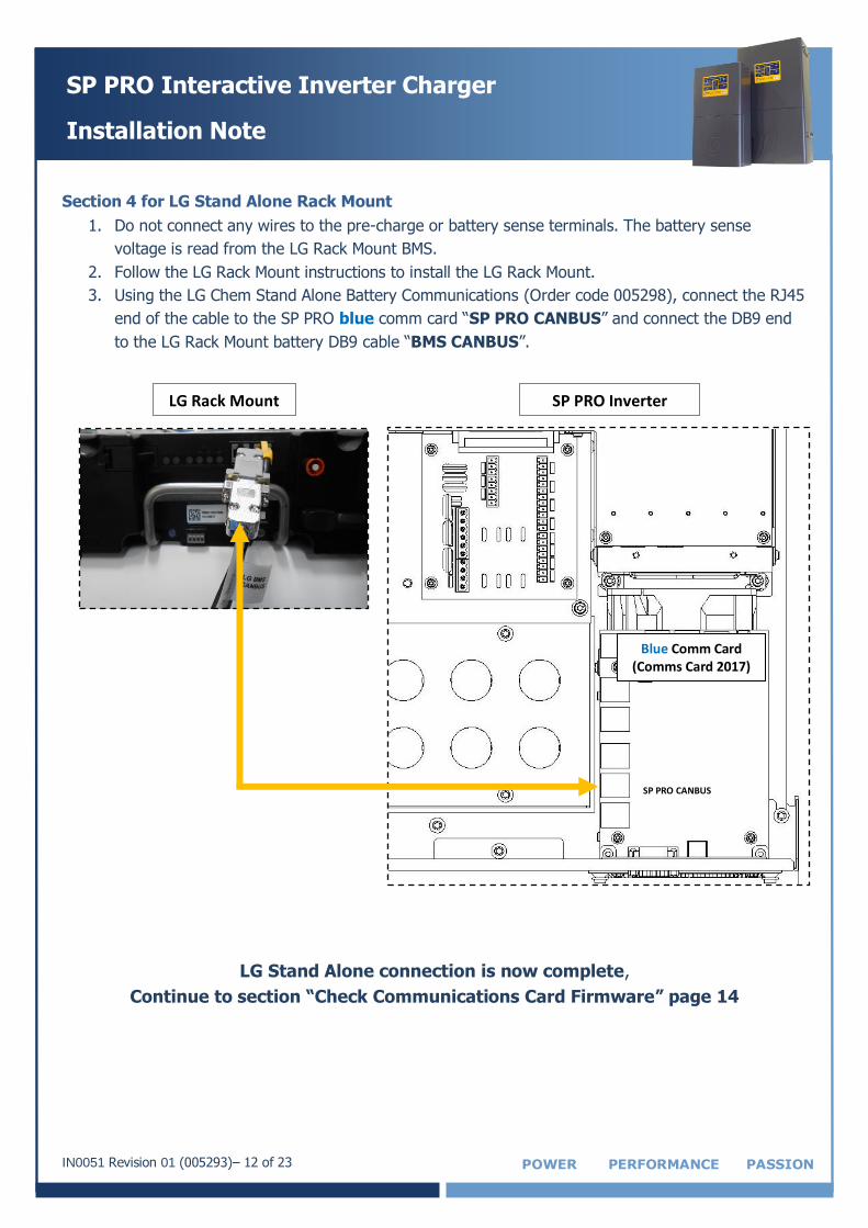
Section 4 for LG Stand Alone Rack Mount
1. Do not connect any wires to the pre-charge or battery sense terminals. The battery sense
voltage is read from the LG Rack Mount BMS.
2. Follow the LG Rack Mount instructions to install the LG Rack Mount.
3. Using the LG Chem Stand Alone Battery Communications (Order code 005298), connect the RJ45
end of the cable to the SP PRO blue comm card “SP PRO CANBUS” and connect the DB9 end
to the LG Rack Mount battery DB9 cable “BMS CANBUS”.
LG Stand Alone connection is now complete,
Continue to section “Check Communications Card Firmware” page 14
SP PRO Inverter
Blue Comm Card (Comms Card 2017)
SP PRO CANBUS
LG Rack Mount
IN0051 Revision 01 (005293)– 13 of 23 POWER PERFORMANCE PASSION
SP PRO Interactive Inverter Charger
Installation Note
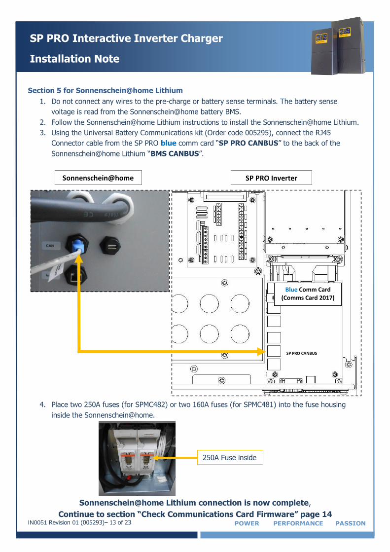
Section 5 for Sonnenschein@home Lithium
1. Do not connect any wires to the pre-charge or battery sense terminals. The battery sense
voltage is read from the Sonnenschein@home battery BMS.
2. Follow the Sonnenschein@home Lithium instructions to install the Sonnenschein@home Lithium.
3. Using the Universal Battery Communications kit (Order code 005295), connect the RJ45
Connector cable from the SP PRO blue comm card “SP PRO CANBUS” to the back of the
Sonnenschein@home Lithium “BMS CANBUS”.
4. Place two 250A fuses (for SPMC482) or two 160A fuses (for SPMC481) into the fuse housing
inside the Sonnenschein@home.
Sonnenschein@home Lithium connection is now complete,
Continue to section “Check Communications Card Firmware” page 14
SP PRO Inverter
Blue Comm Card (Comms Card 2017)
SP PRO CANBUS
Sonnenschein@home
250A Fuse inside
IN0051 Revision 01 (005293)– 14 of 23 POWER PERFORMANCE PASSION
SP PRO Interactive Inverter Charger
Installation Note
Check Communications Card Firmware
The Communication Card firmware must be 1.02 or higher. A Communication Card with firmware 0.05 or higher can be updated using SP LINK.
To check and update the firmware if required, follow the steps below:
1. Connect the DC power to the SP PRO. This is done as follows:
For Sonnenschein@home – Leave the system DC circuit breaker or fuses OFF and turn
the battery ON by pressing the ON button (adjacent to the fuse holder). When the relay
inside the battery clicks, indicating the batteries have come ON, turn ON the system DC
breaker or fuses.
For LG RESU – Turn ON the system DC breaker of fuses to the SP PRO then turn ON the
battery bank circuit breaker(s).
For BYD B-Box, LG Rack Mount – Turn ON the system DC breaker of fuses to the SP PRO
then turn ON the battery bank by pressing the ON button.
Wait until the front panel LEDs are stable.
NOTE: Perform the following tasks quickly as the batteries might shutdown in 5-10 minutes
without the CANBUS communications. If this happens, turn the batteries ON and restart the
process.
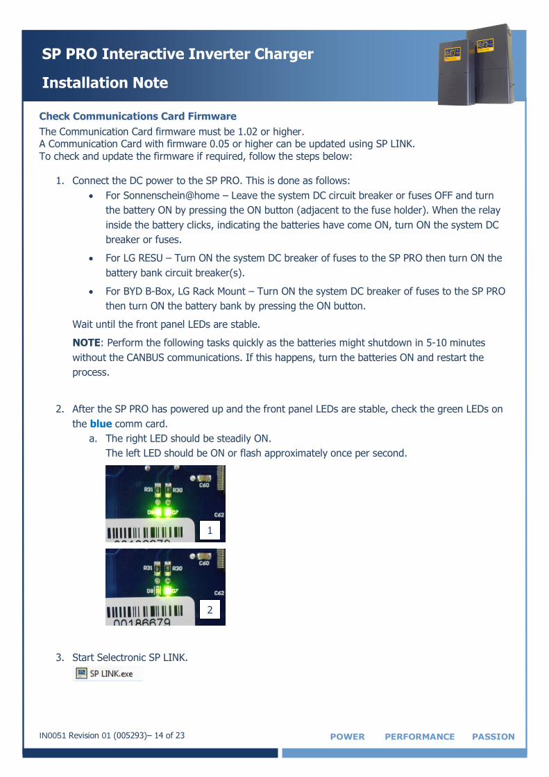
2. After the SP PRO has powered up and the front panel LEDs are stable, check the green LEDs on
the blue comm card.
a. The right LED should be steadily ON.
The left LED should be ON or flash approximately once per second.
3. Start Selectronic SP LINK.
1
2
IN0051 Revision 01 (005293)– 15 of 23 POWER PERFORMANCE PASSION
SP PRO Interactive Inverter Charger
Installation Note
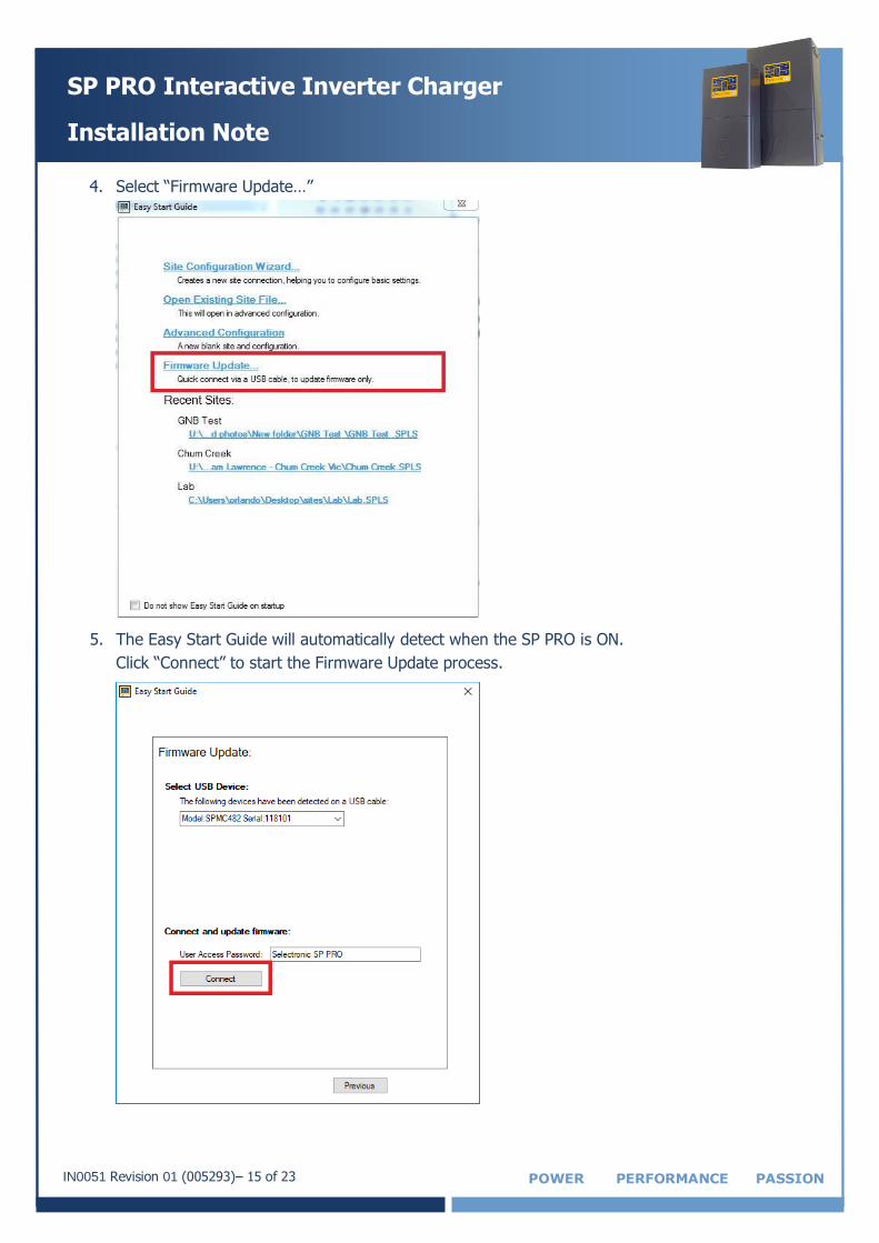
4. Select “Firmware Update…”
5. The Easy Start Guide will automatically detect when the SP PRO is ON.
Click “Connect” to start the Firmware Update process.
IN0051 Revision 01 (005293)– 16 of 23 POWER PERFORMANCE PASSION
SP PRO Interactive Inverter Charger
Installation Note
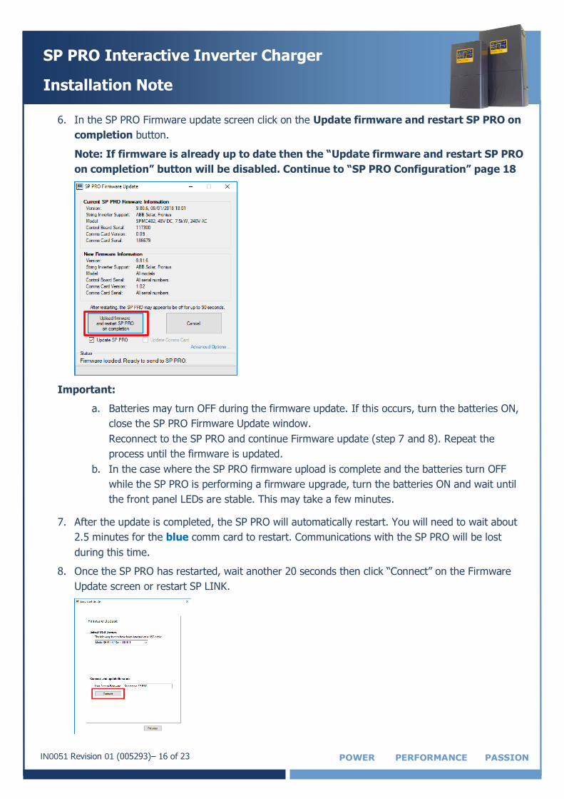
6. In the SP PRO Firmware update screen click on the Update firmware and restart SP PRO on
completion button.
Note: If firmware is already up to date then the “Update firmware and restart SP PRO
on completion” button will be disabled. Continue to “SP PRO Configuration” page 18
Important:
a. Batteries may turn OFF during the firmware update. If this occurs, turn the batteries ON,
close the SP PRO Firmware Update window.
Reconnect to the SP PRO and continue Firmware update (step 7 and 8). Repeat the
process until the firmware is updated.
b. In the case where the SP PRO firmware upload is complete and the batteries turn OFF
while the SP PRO is performing a firmware upgrade, turn the batteries ON and wait until
the front panel LEDs are stable. This may take a few minutes.
7. After the update is completed, the SP PRO will automatically restart. You will need to wait about
2.5 minutes for the blue comm card to restart. Communications with the SP PRO will be lost
during this time.
8. Once the SP PRO has restarted, wait another 20 seconds then click “Connect” on the Firmware
Update screen or restart SP LINK.
IN0051 Revision 01 (005293)– 17 of 23 POWER PERFORMANCE PASSION
SP PRO Interactive Inverter Charger
Installation Note
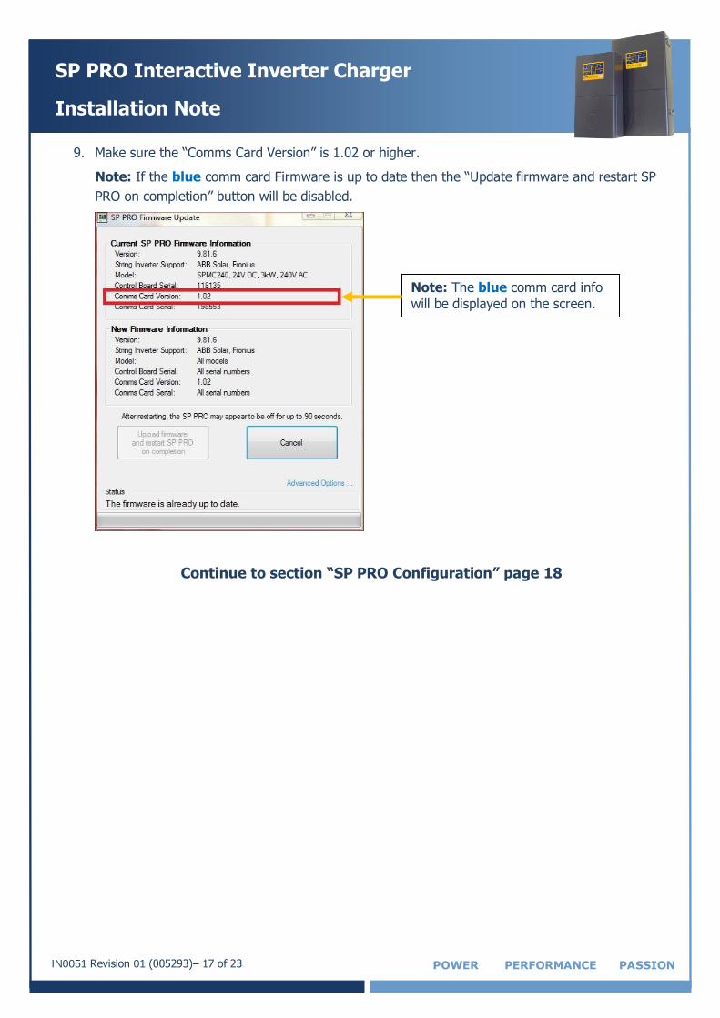
9. Make sure the “Comms Card Version” is 1.02 or higher.
Note: If the blue comm card Firmware is up to date then the “Update firmware and restart SP
PRO on completion” button will be disabled.
Continue to section “SP PRO Configuration” page 18
Note: The blue comm card info
will be displayed on the screen.
IN0051 Revision 01 (005293)– 18 of 23 POWER PERFORMANCE PASSION
SP PRO Interactive Inverter Charger
Installation Note
SP PRO Configuration
1. Make sure the USB lead is connected between the SP PRO and PC.
10. Make sure the DC power is present at the SP PRO.
If NOT then Connect the DC power to the SP PRO. This is done as follows:
For Sonnenschein@home – Leave the system DC circuit breaker or fuses OFF and turn
the battery ON by pressing the ON button (adjacent to the fuse holder). When the relay
inside the battery clicks indicating the batteries have come ON, turn ON the system DC
breaker or fuses.
For LG RESU – Turn ON the system DC breaker of fuses to the SP PRO then turn ON the
battery bank circuit breaker(s).
For BYD B-Box, LG Rack Mount – Turn ON the system DC breaker of fuses to the SP PRO
then turn ON the battery bank by pressing the ON button.
Wait until the front panel LEDs are stable.
NOTE: Perform the following tasks quickly as the batteries might shutdown in 5-10 minutes
without the CANBUS communications. If this happens, turn the batteries ON and restart the
process.
2. Start Selectronic SP LINK.
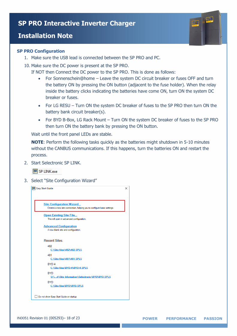
3. Select “Site Configuration Wizard”
IN0051 Revision 01 (005293)– 19 of 23 POWER PERFORMANCE PASSION
SP PRO Interactive Inverter Charger
Installation Note
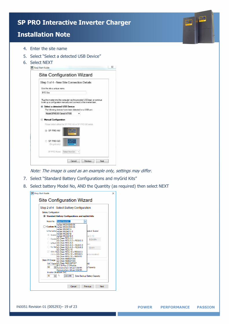
4. Enter the site name
5. Select “Select a detected USB Device”
6. Select NEXT
Note: The image is used as an example only, settings may differ.
7. Select “Standard Battery Configurations and myGrid Kits”
8. Select battery Model No, AND the Quantity (as required) then select NEXT
IN0051 Revision 01 (005293)– 20 of 23 POWER PERFORMANCE PASSION
SP PRO Interactive Inverter Charger
Installation Note
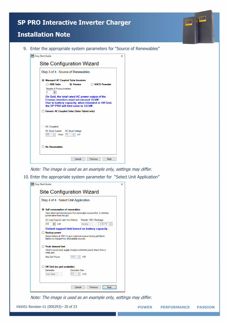
9. Enter the appropriate system parameters for “Source of Renewables”
Note: The image is used as an example only, settings may differ.
10. Enter the appropriate system parameter for “Select Unit Application”
Note: The image is used as an example only, settings may differ.
IN0051 Revision 01 (005293)– 21 of 23 POWER PERFORMANCE PASSION
SP PRO Interactive Inverter Charger
Installation Note
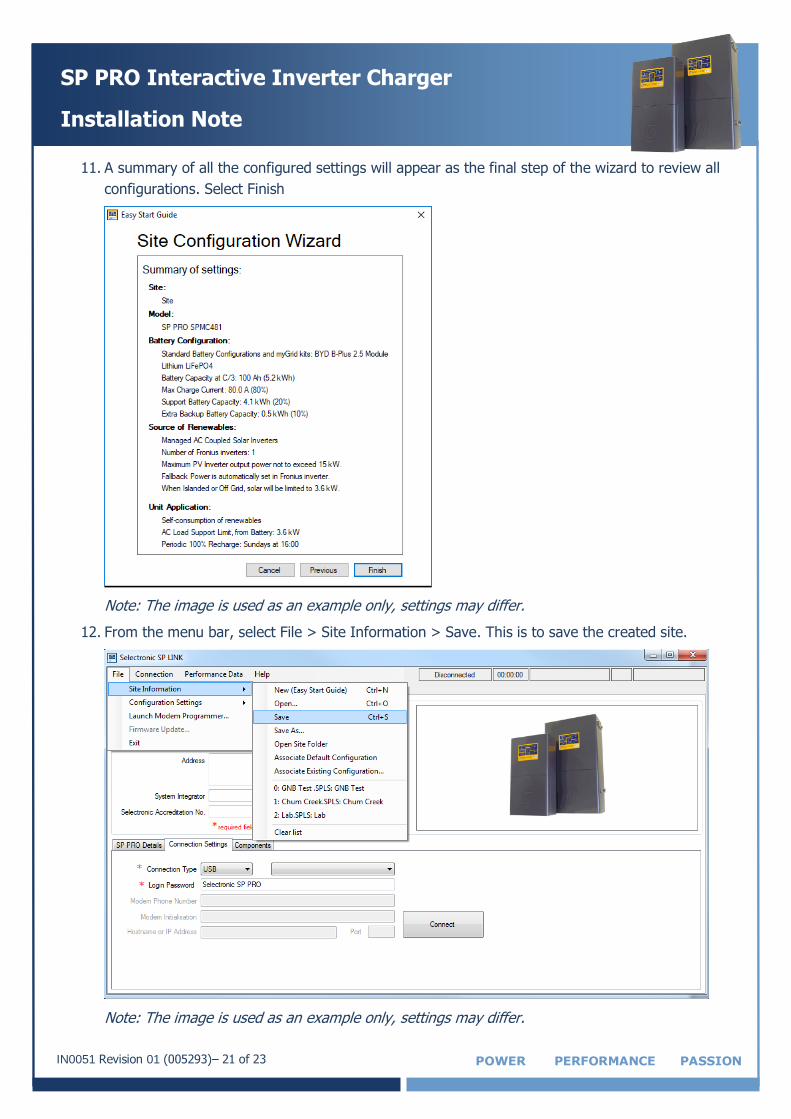
11. A summary of all the configured settings will appear as the final step of the wizard to review all
configurations. Select Finish
Note: The image is used as an example only, settings may differ.
12. From the menu bar, select File > Site Information > Save. This is to save the created site.
Note: The image is used as an example only, settings may differ.
IN0051 Revision 01 (005293)– 22 of 23 POWER PERFORMANCE PASSION
SP PRO Interactive Inverter Charger
Installation Note
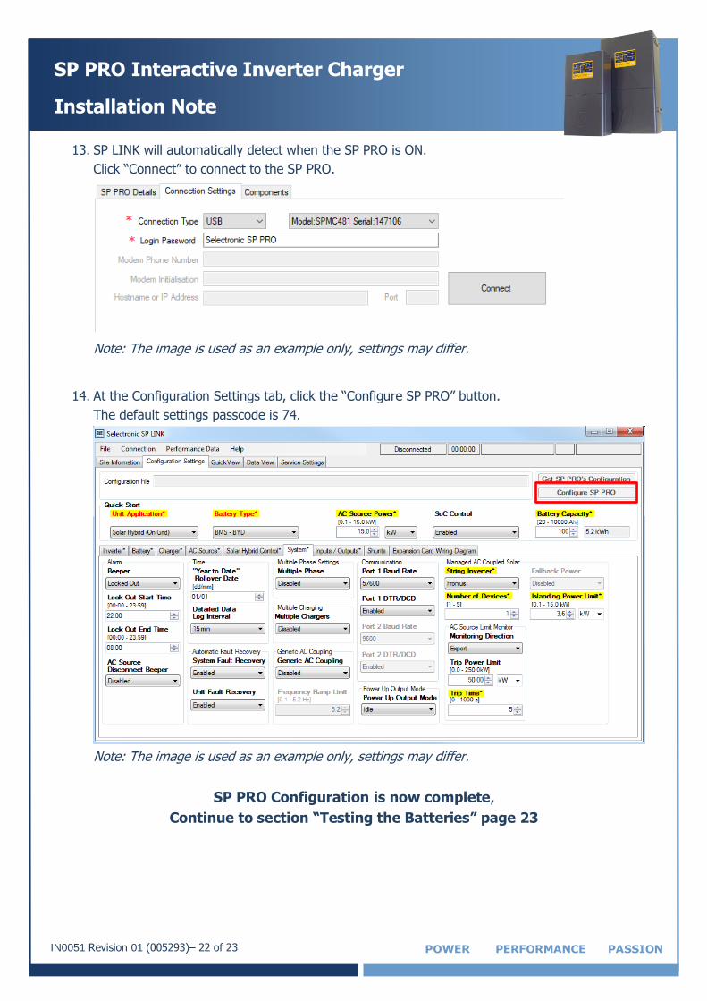
13. SP LINK will automatically detect when the SP PRO is ON.
Click “Connect” to connect to the SP PRO.
Note: The image is used as an example only, settings may differ.
14. At the Configuration Settings tab, click the “Configure SP PRO” button.
The default settings passcode is 74.
Note: The image is used as an example only, settings may differ.
SP PRO Configuration is now complete,
Continue to section “Testing the Batteries” page 23
IN0051 Revision 01 (005293)– 23 of 23 POWER PERFORMANCE PASSION
SP PRO Interactive Inverter Charger
Installation Note
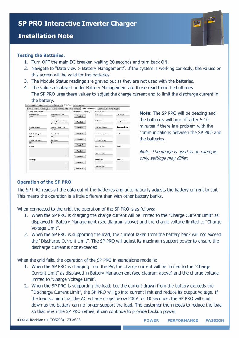
Testing the Batteries.
1. Turn OFF the main DC breaker, waiting 20 seconds and turn back ON.
2. Navigate to “Data view > Battery Management”. If the system is working correctly, the values on
this screen will be valid for the batteries.
3. The Module Status readings are greyed out as they are not used with the batteries.
4. The values displayed under Battery Management are those read from the batteries.
The SP PRO uses these values to adjust the charge current and to limit the discharge current in
the battery.
Note: The SP PRO will be beeping and
the batteries will turn off after 5-10
minutes if there is a problem with the
communications between the SP PRO and
the batteries.
Note: The image is used as an example
only, settings may differ.
Operation of the SP PRO
The SP PRO reads all the data out of the batteries and automatically adjusts the battery current to suit.
This means the operation is a little different than with other battery banks.
When connected to the grid, the operation of the SP PRO is as follows:
1. When the SP PRO is charging the charge current will be limited to the “Charge Current Limit” as
displayed in Battery Management (see diagram above) and the charge voltage limited to “Charge
Voltage Limit”.
2. When the SP PRO is supporting the load, the current taken from the battery bank will not exceed
the “Discharge Current Limit”. The SP PRO will adjust its maximum support power to ensure the
discharge current is not exceeded.
When the grid fails, the operation of the SP PRO in standalone mode is:
1. When the SP PRO is charging from the PV, the charge current will be limited to the “Charge
Current Limit” as displayed in Battery Management (see diagram above) and the charge voltage
limited to “Charge Voltage Limit”.
2. When the SP PRO is supporting the load, but the current drawn from the battery exceeds the
“Discharge Current Limit”, the SP PRO will go into current limit and reduce its output voltage. If
the load so high that the AC voltage drops below 200V for 10 seconds, the SP PRO will shut
down as the battery can no longer support the load. The customer then needs to reduce the load
so that when the SP PRO retries, it can continue to provide backup power.