INSTRUCTION MANUAL - ABB Ltd · 2.3 Swirlmeter Model Number Breakdown ... FIGURE 2-3 METER PIPING...
83
INSTRUCTION MANUAL TRIO-WIRL Flowmeter Swirl ST4000/SR4000 Vortex VT4000/VR4000 PN25080
Transcript of INSTRUCTION MANUAL - ABB Ltd · 2.3 Swirlmeter Model Number Breakdown ... FIGURE 2-3 METER PIPING...

INSTRUCTION MANUAL
TRIO-WIRL FlowmeterSwirl ST4000/SR4000Vortex VT4000/VR4000
PN25080
Copyright 2003 ABB Inc. [June 2003]
Trademarks and Registrations
Registrations and trademarks used in this document include:
® Windows Registered trademark of Microsoft Incorporated® SMART VISION Registered trademark of ABB Inc.® Delrin Registered trademark of E.I. DuPont de Nemours Company, Incorporated® Lexan Registered trademark of General Electric Company, GE Plastics Division® Valox Registered trademark of General Electric Company, GE Plastics Division
WARNING notices as used in this manual apply to hazards or unsafe practices which could result in personalinjury or death.
CAUTION notices apply to hazards or unsafe practices which could result in property damage.
NOTES highlight procedures and contain information which assist the operator in understanding the informa-tion contained in this manual.
All software, including design, appearance, algorithms and source codes, is copyrighted by ABB Inc. and isowned by ABB Inc. or its suppliers.
WARNING
POSSIBLE PROCESS UPSETS. Maintenance must be performed only by qualified personnel and only aftersecuring equipment controlled by this product. Adjusting or removing this product while it is in the system mayupset the process being controlled. Some process upsets may cause injury or damage.
NOTICE
The information contained in this document is subject to change without notice.
ABB Inc., its affiliates, employees, and agents, and the authors of and contributors to this publication specifi-cally disclaim all liabilities and warranties, express and implied (including warranties of merchantability and fit-ness for a particular purpose), for the accuracy, currency, completeness, and/or reliability of the informationcontained herein and/or for the fitness for any particular use and/or for the performance of any material and/orequipment selected in whole or part with the user of/or in reliance upon information contained herein. Selectionof materials and/or equipment is at the sole risk of the user of this publication.
This document contains proprietary information of ABB Inc., and is issued in strict confidence. Its use, or repro-duction for use, for the reverse engineering, development or manufacture of hardware or software describedherein is prohibited. No part of this document may be photocopied or reproduced without the prior written con-sent of ABB Inc..
Table of ContentsPage
TRIO-WIRL INSTRUCTION MANUAL
Read First . . . . . . . . . . . . . . . . . . . . . . . . . . . . . . . . . . . . . . . . . . . . . . . . . . I
CHAPTER 1 Introduction . . . . . . . . . . . . . . . . . . . . . . . . . . . . . . . . . . . 1-11.1 Description . . . . . . . . . . . . . . . . . . . . . . . . . . . . . . . . . . . . . . . . . . . . . . . . . . . . . . . . . . . . . . . 1-11.2 Features . . . . . . . . . . . . . . . . . . . . . . . . . . . . . . . . . . . . . . . . . . . . . . . . . . . . . . . . . . . . . . . . . 1-21.3 Organization. . . . . . . . . . . . . . . . . . . . . . . . . . . . . . . . . . . . . . . . . . . . . . . . . . . . . . . . . . . . . . 1-2
CHAPTER 2 Swirlmeter (TRIO-WIRL S). . . . . . . . . . . . . . . . . . . . . . . . 2-12.1 General . . . . . . . . . . . . . . . . . . . . . . . . . . . . . . . . . . . . . . . . . . . . . . . . . . . . . . . . . . . . . . . . . 2-12.2 Measurement Principle . . . . . . . . . . . . . . . . . . . . . . . . . . . . . . . . . . . . . . . . . . . . . . . . . . . . . 2-1
2.2.1 Liquid Flow Back Pressure . . . . . . . . . . . . . . . . . . . . . . . . . . . . . . . . . . . . . . . . . . . . . . 2-12.3 Swirlmeter Model Number Breakdown. . . . . . . . . . . . . . . . . . . . . . . . . . . . . . . . . . . . . . . . . . 2-22.4 Installation . . . . . . . . . . . . . . . . . . . . . . . . . . . . . . . . . . . . . . . . . . . . . . . . . . . . . . . . . . . . . . . 2-4
2.4.1 Inspection . . . . . . . . . . . . . . . . . . . . . . . . . . . . . . . . . . . . . . . . . . . . . . . . . . . . . . . . . . . 2-42.4.2 Location & Mounting. . . . . . . . . . . . . . . . . . . . . . . . . . . . . . . . . . . . . . . . . . . . . . . . . . . 2-4
2.4.2.1 Installation . . . . . . . . . . . . . . . . . . . . . . . . . . . . . . . . . . . . . . . . . . . . . . . . . . . . 2-42.4.2.2 Recommended Inlet & Outlet Sections . . . . . . . . . . . . . . . . . . . . . . . . . . . . . . 2-42.4.2.3 Control Valve Installation . . . . . . . . . . . . . . . . . . . . . . . . . . . . . . . . . . . . . . . . . 2-52.4.2.4 Extreme Temperature Applications . . . . . . . . . . . . . . . . . . . . . . . . . . . . . . . . . 2-5
2.4.3 Temperature/Pressure Monitoring . . . . . . . . . . . . . . . . . . . . . . . . . . . . . . . . . . . . . . . . 2-72.5 Swirlmeter Size Selection . . . . . . . . . . . . . . . . . . . . . . . . . . . . . . . . . . . . . . . . . . . . . . . . . . . 2-7
2.5.1 Gas . . . . . . . . . . . . . . . . . . . . . . . . . . . . . . . . . . . . . . . . . . . . . . . . . . . . . . . . . . . . . . . . 2-72.5.1.1 QVMIN for Gases with Density < 0.0749 lb/ft3 . . . . . . . . . . . . . . . . . . . . . . . . 2-72.5.1.2 Example for Gases: . . . . . . . . . . . . . . . . . . . . . . . . . . . . . . . . . . . . . . . . . . . . . 2-82.5.1.3 Pressure Drop, Gas & Steam . . . . . . . . . . . . . . . . . . . . . . . . . . . . . . . . . . . . . 2-8
2.5.2 Liquid . . . . . . . . . . . . . . . . . . . . . . . . . . . . . . . . . . . . . . . . . . . . . . . . . . . . . . . . . . . . . 2-102.5.2.1 Example for Liquids . . . . . . . . . . . . . . . . . . . . . . . . . . . . . . . . . . . . . . . . . . . . 2-10
2.5.3 Saturated Steam. . . . . . . . . . . . . . . . . . . . . . . . . . . . . . . . . . . . . . . . . . . . . . . . . . . . . 2-112.5.3.1 Example for Saturated Steam . . . . . . . . . . . . . . . . . . . . . . . . . . . . . . . . . . . . 2-11
2.6 Specifications . . . . . . . . . . . . . . . . . . . . . . . . . . . . . . . . . . . . . . . . . . . . . . . . . . . . . . . . . . . . 2-132.6.1 Model Overview . . . . . . . . . . . . . . . . . . . . . . . . . . . . . . . . . . . . . . . . . . . . . . . . . . . . . 2-132.6.2 Detailed Specifications . . . . . . . . . . . . . . . . . . . . . . . . . . . . . . . . . . . . . . . . . . . . . . . . 2-14
CHAPTER 3 Vortex Meter (TRIO-WIRL V) . . . . . . . . . . . . . . . . . . . . . . 3-13.1 General . . . . . . . . . . . . . . . . . . . . . . . . . . . . . . . . . . . . . . . . . . . . . . . . . . . . . . . . . . . . . . . . . 3-13.2 Measurement Principle . . . . . . . . . . . . . . . . . . . . . . . . . . . . . . . . . . . . . . . . . . . . . . . . . . . . . 3-13.3 Vortex Model Number Breakdown . . . . . . . . . . . . . . . . . . . . . . . . . . . . . . . . . . . . . . . . . . . . . 3-33.4 Installation . . . . . . . . . . . . . . . . . . . . . . . . . . . . . . . . . . . . . . . . . . . . . . . . . . . . . . . . . . . . . . . 3-5
3.4.1 Inspection . . . . . . . . . . . . . . . . . . . . . . . . . . . . . . . . . . . . . . . . . . . . . . . . . . . . . . . . . . . 3-53.4.2 Location & Mounting. . . . . . . . . . . . . . . . . . . . . . . . . . . . . . . . . . . . . . . . . . . . . . . . . . . 3-5
3.4.2.1 Installation . . . . . . . . . . . . . . . . . . . . . . . . . . . . . . . . . . . . . . . . . . . . . . . . . . . . 3-53.4.2.2 Recommended Inlet & Outlet Sections . . . . . . . . . . . . . . . . . . . . . . . . . . . . . . 3-5
PN24993 Table of Contents i

Page
TRIO-WIRL INSTRUCTION MANUAL
Table of Contents (cont.)
3.4.2.3 Wafer-Style Installation. . . . . . . . . . . . . . . . . . . . . . . . . . . . . . . . . . . . . . . . . . 3-63.4.2.4 Flanged-Style Installation . . . . . . . . . . . . . . . . . . . . . . . . . . . . . . . . . . . . . . . . 3-83.4.2.5 Control Valve Installation . . . . . . . . . . . . . . . . . . . . . . . . . . . . . . . . . . . . . . . . 3-93.4.2.6 Extreme Temperature Applications . . . . . . . . . . . . . . . . . . . . . . . . . . . . . . . . 3-9
3.4.3 Temperature/Pressure Monitoring. . . . . . . . . . . . . . . . . . . . . . . . . . . . . . . . . . . . . . . 3-103.5 Vortex Meter Size Selection . . . . . . . . . . . . . . . . . . . . . . . . . . . . . . . . . . . . . . . . . . . . . . . . 3-11
3.5.1 Gas . . . . . . . . . . . . . . . . . . . . . . . . . . . . . . . . . . . . . . . . . . . . . . . . . . . . . . . . . . . . . . 3-113.5.1.1 Example for Gases . . . . . . . . . . . . . . . . . . . . . . . . . . . . . . . . . . . . . . . . . . . . 3-123.5.1.2 Pressure Drop, Gas/Superheated Steam . . . . . . . . . . . . . . . . . . . . . . . . . . . 3-123.5.1.3 Flowrate Saturated Steam . . . . . . . . . . . . . . . . . . . . . . . . . . . . . . . . . . . . . . 3-12
3.5.2 Liquid. . . . . . . . . . . . . . . . . . . . . . . . . . . . . . . . . . . . . . . . . . . . . . . . . . . . . . . . . . . . . 3-143.5.2.1 Static Pressure, Liquid . . . . . . . . . . . . . . . . . . . . . . . . . . . . . . . . . . . . . . . . . 3-143.5.2.2 Pressure Drop, Liquid . . . . . . . . . . . . . . . . . . . . . . . . . . . . . . . . . . . . . . . . . . 3-14
3.6 Specifications . . . . . . . . . . . . . . . . . . . . . . . . . . . . . . . . . . . . . . . . . . . . . . . . . . . . . . . . . . . 3-163.6.1 Model Overview. . . . . . . . . . . . . . . . . . . . . . . . . . . . . . . . . . . . . . . . . . . . . . . . . . . . . 3-163.6.2 Detailed Specifications . . . . . . . . . . . . . . . . . . . . . . . . . . . . . . . . . . . . . . . . . . . . . . . 3-17
CHAPTER 4 Converter . . . . . . . . . . . . . . . . . . . . . . . . . . . . . . . . . . . . . 4-14.1 General . . . . . . . . . . . . . . . . . . . . . . . . . . . . . . . . . . . . . . . . . . . . . . . . . . . . . . . . . . . . . . . . . 4-14.2 Converter Positioning . . . . . . . . . . . . . . . . . . . . . . . . . . . . . . . . . . . . . . . . . . . . . . . . . . . . . . 4-24.3 Data Entry . . . . . . . . . . . . . . . . . . . . . . . . . . . . . . . . . . . . . . . . . . . . . . . . . . . . . . . . . . . . . . . 4-2
4.3.1 ENTER Function for Magnetic Stick Operation . . . . . . . . . . . . . . . . . . . . . . . . . . . . . . 4-34.3.2 Data Entry Overview . . . . . . . . . . . . . . . . . . . . . . . . . . . . . . . . . . . . . . . . . . . . . . . . . . 4-4
4.4 Operation and Configuration . . . . . . . . . . . . . . . . . . . . . . . . . . . . . . . . . . . . . . . . . . . . . . . . . 4-54.5 Digital Communications Protocols . . . . . . . . . . . . . . . . . . . . . . . . . . . . . . . . . . . . . . . . . . . . 4-5
4.5.1 HART Protocol. . . . . . . . . . . . . . . . . . . . . . . . . . . . . . . . . . . . . . . . . . . . . . . . . . . . . . . 4-54.5.1.1 Communication. . . . . . . . . . . . . . . . . . . . . . . . . . . . . . . . . . . . . . . . . . . . . . . . 4-54.5.1.2 Transmission Mode . . . . . . . . . . . . . . . . . . . . . . . . . . . . . . . . . . . . . . . . . . . . 4-54.5.1.3 Baudrate . . . . . . . . . . . . . . . . . . . . . . . . . . . . . . . . . . . . . . . . . . . . . . . . . . . . . 4-6
4.6 Specifications . . . . . . . . . . . . . . . . . . . . . . . . . . . . . . . . . . . . . . . . . . . . . . . . . . . . . . . . . . . . 4-74.6.1 Overview . . . . . . . . . . . . . . . . . . . . . . . . . . . . . . . . . . . . . . . . . . . . . . . . . . . . . . . . . . . 4-74.6.2 Detailed Specifications . . . . . . . . . . . . . . . . . . . . . . . . . . . . . . . . . . . . . . . . . . . . . . . . 4-8
CHAPTER 5 Start-Up & Operation . . . . . . . . . . . . . . . . . . . . . . . . . . . 5-15.1 Start-Up. . . . . . . . . . . . . . . . . . . . . . . . . . . . . . . . . . . . . . . . . . . . . . . . . . . . . . . . . . . . . . . . . 5-1
5.1.1 Calibration Parameters . . . . . . . . . . . . . . . . . . . . . . . . . . . . . . . . . . . . . . . . . . . . . . . . 5-15.1.2 Firmware Version . . . . . . . . . . . . . . . . . . . . . . . . . . . . . . . . . . . . . . . . . . . . . . . . . . . . 5-15.1.3 Program Protection . . . . . . . . . . . . . . . . . . . . . . . . . . . . . . . . . . . . . . . . . . . . . . . . . . . 5-15.1.4 Error Messages . . . . . . . . . . . . . . . . . . . . . . . . . . . . . . . . . . . . . . . . . . . . . . . . . . . . . . 5-1
5.2 Electrical Interconnections . . . . . . . . . . . . . . . . . . . . . . . . . . . . . . . . . . . . . . . . . . . . . . . . . . 5-15.2.1 TRIO-WIRL VT/ST4000 Integral . . . . . . . . . . . . . . . . . . . . . . . . . . . . . . . . . . . . . . . . . 5-15.2.2 TRIO-WIRL VR/SR4000 Remote . . . . . . . . . . . . . . . . . . . . . . . . . . . . . . . . . . . . . . . . 5-25.2.3 Power Supply Interconnections . . . . . . . . . . . . . . . . . . . . . . . . . . . . . . . . . . . . . . . . . . 5-3
5.2.3.1 Power Supplied from a Central Power Supply . . . . . . . . . . . . . . . . . . . . . . . . 5-35.2.3.2 Power Supplied from Transmitter Power Supply . . . . . . . . . . . . . . . . . . . . . . 5-35.2.3.3 Hazardous Location Installation . . . . . . . . . . . . . . . . . . . . . . . . . . . . . . . . . . . 5-3
5.2.4 Contact Output Connections . . . . . . . . . . . . . . . . . . . . . . . . . . . . . . . . . . . . . . . . . . . . 5-5
Table of Contents ii PN24993

Page
Table of Contents (cont.)
TRIO-WIRL INSTRUCTION MANUAL
5.3 Converter Configuration. . . . . . . . . . . . . . . . . . . . . . . . . . . . . . . . . . . . . . . . . . . . . . . . . . . . . 5-55.3.1 Data-Entry Check . . . . . . . . . . . . . . . . . . . . . . . . . . . . . . . . . . . . . . . . . . . . . . . . . . . . . 5-55.3.2 Additional Configuration Information . . . . . . . . . . . . . . . . . . . . . . . . . . . . . . . . . . . . . . 5-5
5.3.2.1 Meter Size . . . . . . . . . . . . . . . . . . . . . . . . . . . . . . . . . . . . . . . . . . . . . . . . . . . . 5-55.3.2.2 Calibration K-Factor . . . . . . . . . . . . . . . . . . . . . . . . . . . . . . . . . . . . . . . . . . . . 5-65.3.2.3 Current Output. . . . . . . . . . . . . . . . . . . . . . . . . . . . . . . . . . . . . . . . . . . . . . . . . 5-65.3.2.4 Hardware Configuration. . . . . . . . . . . . . . . . . . . . . . . . . . . . . . . . . . . . . . . . . . 5-65.3.2.5 Submenu Pulse Output . . . . . . . . . . . . . . . . . . . . . . . . . . . . . . . . . . . . . . . . . . 5-75.3.2.6 Normal Factor . . . . . . . . . . . . . . . . . . . . . . . . . . . . . . . . . . . . . . . . . . . . . . . . . 5-7
5.3.3 Configuring the Contact Output . . . . . . . . . . . . . . . . . . . . . . . . . . . . . . . . . . . . . . . . . . 5-85.4 TRIO-WIRL Menu Structure . . . . . . . . . . . . . . . . . . . . . . . . . . . . . . . . . . . . . . . . . . . . . . . . . 5-9
5.4.1 Configuring Gases, Steam or Liquids. . . . . . . . . . . . . . . . . . . . . . . . . . . . . . . . . . . . . . 5-95.5 Trio-Wirl Menu Display and Selections . . . . . . . . . . . . . . . . . . . . . . . . . . . . . . . . . . . . . . . . 5-10
5.5.1 Changing The Displayed Language. . . . . . . . . . . . . . . . . . . . . . . . . . . . . . . . . . . . . . 5-105.5.2 Turning Locked Mode On/ Off . . . . . . . . . . . . . . . . . . . . . . . . . . . . . . . . . . . . . . . . . . 5-115.5.3 Top-Level Menu Structure . . . . . . . . . . . . . . . . . . . . . . . . . . . . . . . . . . . . . . . . . . . . . 5-135.5.4 Complete Menu Structure Overview and Data Entry . . . . . . . . . . . . . . . . . . . . . . . . . 5-145.5.5 Submenu Error Register. . . . . . . . . . . . . . . . . . . . . . . . . . . . . . . . . . . . . . . . . . . . . . . 5-20
5.5.5.1 Error Display . . . . . . . . . . . . . . . . . . . . . . . . . . . . . . . . . . . . . . . . . . . . . . . . . 5-20
CHAPTER 6 Troubleshooting . . . . . . . . . . . . . . . . . . . . . . . . . . . . . . . 6-1
CHAPTER 7 Parts List . . . . . . . . . . . . . . . . . . . . . . . . . . . . . . . . . . . . . 7-17.1 Replacement Parts . . . . . . . . . . . . . . . . . . . . . . . . . . . . . . . . . . . . . . . . . . . . . . . . . . . . . . . . 7-1
7.1.1 Flowmeter/Signal Converter Parts . . . . . . . . . . . . . . . . . . . . . . . . . . . . . . . . . . . . . . . . 7-37.1.2 Kits / Accessories . . . . . . . . . . . . . . . . . . . . . . . . . . . . . . . . . . . . . . . . . . . . . . . . . . . 7-47.1.3 Flange Gaskets . . . . . . . . . . . . . . . . . . . . . . . . . . . . . . . . . . . . . . . . . . . . . . . . . . . . . . 7-6
PN24993 Table of Contents iii

Page
TRIO-WIRL INSTRUCTION MANUAL
List of Figures
FIGURE 2-1 MEASUREMENT PRINCIPLE, TRIO-WIRL S . . . . . . . . . . . . . . . . . . . . . . . . . . . . . . . . 2-1FIGURE 2-2 OPERATING PRINCIPLE, TRIO-WIRL S . . . . . . . . . . . . . . . . . . . . . . . . . . . . . . . . . . . 2-1FIGURE 2-3 METER PIPING REQUIREMENTS . . . . . . . . . . . . . . . . . . . . . . . . . . . . . . . . . . . . . . . . 2-5FIGURE 2-4 RECOMMENDED FLANGE BOLT TIGHTENING SEQUENCE . . . . . . . . . . . . . . . . . . 2-5FIGURE 2-5 CONTROL VALVE INSTALLATION. . . . . . . . . . . . . . . . . . . . . . . . . . . . . . . . . . . . . . . . 2-5FIGURE 2-6 INSULATING THE PIPELINE. . . . . . . . . . . . . . . . . . . . . . . . . . . . . . . . . . . . . . . . . . . . . 2-6FIGURE 2-7 ORIENTATION FOR TEMPERATURES >300° F (150° C) . . . . . . . . . . . . . . . . . . . . . . 2-6FIGURE 2-8 AMBIENT/FLUID TEMPERATURE RELATIONSHIP. . . . . . . . . . . . . . . . . . . . . . . . . . . 2-6FIGURE 2-9 MEASURING PRESSURE. . . . . . . . . . . . . . . . . . . . . . . . . . . . . . . . . . . . . . . . . . . . . . . 2-7FIGURE 2-10 PRESSURE DROP, AIR. . . . . . . . . . . . . . . . . . . . . . . . . . . . . . . . . . . . . . . . . . . . . . . . . 2-9FIGURE 2-11 PRESSURE DROP, WATER . . . . . . . . . . . . . . . . . . . . . . . . . . . . . . . . . . . . . . . . . . . . 2-11FIGURE 2-12 AMBIENT / FLUID TEMPERATURE RELATIONSHIP. . . . . . . . . . . . . . . . . . . . . . . . . 2-15FIGURE 2-13 PROCESS PRESSURE VS. PROCESS FLUID TEMPERATURE . . . . . . . . . . . . . . . 2-15FIGURE 2-14 OUTLINE DIMENSIONS, ST/SR PRIMARY . . . . . . . . . . . . . . . . . . . . . . . . . . . . . . . . 2-16
FIGURE 3-1 FLOW MEASUREMENT PRINCIPLE, TRIO-WIRL V . . . . . . . . . . . . . . . . . . . . . . . . . . 3-1FIGURE 3-2 STROUHAL NUMBER / REYNOLDS NUMBER RELATIONSHIP. . . . . . . . . . . . . . . . . 3-1FIGURE 3-3 OPERATING PRINCIPLE, TRIO-WIRL V . . . . . . . . . . . . . . . . . . . . . . . . . . . . . . . . . . . 3-2FIGURE 3-4 METER PIPING REQUIREMENTS . . . . . . . . . . . . . . . . . . . . . . . . . . . . . . . . . . . . . . . . 3-6FIGURE 3-5 WAFER PROCESS CONNECTIONS, SIZES 1/2 THROUGH 2 INCHES . . . . . . . . . . . 3-7FIGURE 3-6 WAFER PROCESS CONNECTIONS, SIZES 3 THROUGH 8 INCHES . . . . . . . . . . . . 3-8FIGURE 3-7 WAFER STYLE ASSEMBLY . . . . . . . . . . . . . . . . . . . . . . . . . . . . . . . . . . . . . . . . . . . . . 3-8FIGURE 3-9 FLANGE PROCESS CONNECTIONS. . . . . . . . . . . . . . . . . . . . . . . . . . . . . . . . . . . . . . 3-9FIGURE 3-8 RECOMMENDED FLANGE BOLT TIGHTENING SEQUENCE . . . . . . . . . . . . . . . . . . 3-9FIGURE 3-10 CONTROL VALVE INSTALLATION . . . . . . . . . . . . . . . . . . . . . . . . . . . . . . . . . . . . . . . . 3-9FIGURE 3-12 ORIENTATION FOR TEMPERATURES >300° F (150° C) . . . . . . . . . . . . . . . . . . . . . 3-10FIGURE 3-11 INSULATING THE PIPELINE. . . . . . . . . . . . . . . . . . . . . . . . . . . . . . . . . . . . . . . . . . . . 3-10FIGURE 3-13 AMBIENT/FLUID TEMPERATURE RELATIONSHIP. . . . . . . . . . . . . . . . . . . . . . . . . . 3-10FIGURE 3-14 PRESSURE DROP, AIR. . . . . . . . . . . . . . . . . . . . . . . . . . . . . . . . . . . . . . . . . . . . . . . . 3-13FIGURE 3-15 PRESSURE DROP, WATER . . . . . . . . . . . . . . . . . . . . . . . . . . . . . . . . . . . . . . . . . . . . 3-15FIGURE 3-16 AMBIENT / FLUID TEMPERATURE RELATIONSHIP. . . . . . . . . . . . . . . . . . . . . . . . . 3-18FIGURE 3-17 PROCESS PRESSURE VS. PROCESS FLUID TEMPERATURE . . . . . . . . . . . . . . . 3-18FIGURE 3-18 OUTLINE DIMENSIONS, VT/VR PRIMARY . . . . . . . . . . . . . . . . . . . . . . . . . . . . . . . . 3-19
FIGURE 4-1 INTEGRAL TRIO-WIRL MODEL VT . . . . . . . . . . . . . . . . . . . . . . . . . . . . . . . . . . . . . . . 4-1FIGURE 4-2 REMOTE TRIO-WIRL MODEL VR . . . . . . . . . . . . . . . . . . . . . . . . . . . . . . . . . . . . . . . . 4-1FIGURE 4-3 VR/SR PIPE-MOUNT BRACKET. . . . . . . . . . . . . . . . . . . . . . . . . . . . . . . . . . . . . . . . . . 4-1FIGURE 4-4 CONVERTER HOUSING ROTATION . . . . . . . . . . . . . . . . . . . . . . . . . . . . . . . . . . . . . . 4-2FIGURE 4-5 CONVERTER KEYPAD & DISPLAY . . . . . . . . . . . . . . . . . . . . . . . . . . . . . . . . . . . . . . . 4-3FIGURE 4-6 HART-COMMUNICATION . . . . . . . . . . . . . . . . . . . . . . . . . . . . . . . . . . . . . . . . . . . . . . . 4-6FIGURE 4-7 CONVERTER KEYPAD AND DISPLAY . . . . . . . . . . . . . . . . . . . . . . . . . . . . . . . . . . . . 4-8FIGURE 4-8 OUTLINE DIMENSIONS, VR/SR IN WALL-MOUNT HOUSING . . . . . . . . . . . . . . . . . . 4-9
FIGURE 5-1 INSTRUMENT DATA TAG . . . . . . . . . . . . . . . . . . . . . . . . . . . . . . . . . . . . . . . . . . . . . . . 5-1FIGURE 5-2 CONNECTION BOX TRIO-WIRL. . . . . . . . . . . . . . . . . . . . . . . . . . . . . . . . . . . . . . . . . . 5-2FIGURE 5-3 TRIO-WIRL VR/SR . . . . . . . . . . . . . . . . . . . . . . . . . . . . . . . . . . . . . . . . . . . . . . . . . . . . 5-2FIGURE 5-4 CONNECTION BOX TRIO-WIRL VR/SR FLOWMETER PRIMARY . . . . . . . . . . . . . . . 5-2FIGURE 5-5 INTERCONNECTIONS BETWEEN CONVERTER AND FLOWMETER PRIMARY . . . 5-3FIGURE 5-6 CENTRAL POWER SUPPLY. . . . . . . . . . . . . . . . . . . . . . . . . . . . . . . . . . . . . . . . . . . . . 5-3
List of Figures iv PN24993

Page
List of Figures (cont.)
TRIO-WIRL INSTRUCTION MANUAL
List of Tables
FIGURE 5-7 TRANSMITTER POWER SUPPLY. . . . . . . . . . . . . . . . . . . . . . . . . . . . . . . . . . . . . . . . . 5-3FIGURE 5-8 LOAD DIAGRAM . . . . . . . . . . . . . . . . . . . . . . . . . . . . . . . . . . . . . . . . . . . . . . . . . . . . . . 5-3FIGURE 5-9 POWER SUPPLY INTERCONNECTION DIAGRAM, HAZARDOUS LOCATIONS . . . . 5-4FIGURE 5-10 FM / CSA LABEL . . . . . . . . . . . . . . . . . . . . . . . . . . . . . . . . . . . . . . . . . . . . . . . . . . . . . . 5-4FIGURE 5-11 CONTACT OUTPUT CONNECTION . . . . . . . . . . . . . . . . . . . . . . . . . . . . . . . . . . . . . . . 5-5FIGURE 5-12 RELATIONSHIP RE AT THE CONTACT OUTPUT AS A FUNCTION OF V & I . . . . . . 5-5FIGURE 5-13 OUTPUT CURRENT CHARACTERISTICS . . . . . . . . . . . . . . . . . . . . . . . . . . . . . . . . . . 5-6FIGURE 5-14 CONVERTER PCB MODULE MOUNTING SCREW LOCATION. . . . . . . . . . . . . . . . . . 5-8FIGURE 5-15 KIT-FRAM INSTALLATION . . . . . . . . . . . . . . . . . . . . . . . . . . . . . . . . . . . . . . . . . . . . . . . 5-8FIGURE 5-16 CONTACT OUTPUT CIRCUITS. . . . . . . . . . . . . . . . . . . . . . . . . . . . . . . . . . . . . . . . . . . 5-9
FIGURE 7-1 FLOWMETER/SIGNAL CONVERTER PARTS . . . . . . . . . . . . . . . . . . . . . . . . . . . . . . . 7-2
TABLE 2-1. SWIRL FLOW RANGES, AIR .............................................................................................. 2-7TABLE 2-2. STANDARD DENSITIES FOR SELECTED GASES ........................................................... 2-8TABLE 2-3. SWIRL FLOW RANGES, LIQUID ...................................................................................... 2-10TABLE 2-4. SWIRL FLOW RANGES, SATURATED STEAM ............................................................... 2-12
TABLE 3-1. VORTEX FLOW RANGES, AIR......................................................................................... 3-11TABLE 3-2. STANDARD DENSITIES FOR SELECTED GASES ......................................................... 3-11TABLE 3-3. MINIMUM & MAXIMUM FLOWRATES VS. DENSITY, GASES & STEAM ....................... 3-12TABLE 3-4. VORTEX FLOW RANGES, SATURATED STEAM............................................................ 3-13TABLE 3-5. VORTEX FLOW RANGES, WATER.................................................................................. 3-14TABLE 3-6. MINIMUM & MAXIMUM FLOWRATES VS. VISCOSITY, LIQUID.................................... 3-14
TABLE 5-1. TOP-LEVEL MENU STRUCTURE..................................................................................... 5-14TABLE 5-2. ERROR CODE LISTING.................................................................................................... 5-21
TABLE 7-1. FLOWMETER/SIGNAL CONVERTER PARTS LIST........................................................... 7-3TABLE 7-2. KITS / ACCESSORIES ........................................................................................................ 7-4TABLE 7-3. CENTERING RINGS, VORTEX WAFER............................................................................. 7-5TABLE 7-4. METER MOUNTING KITS, VORTEX WAFER .................................................................... 7-5TABLE 7-5. FLANGE GASKETS............................................................................................................. 7-6
PN24993 List of Figures v

TRIO-WIRL INSTRUCTION MANUAL
Read First
WARNING
INSTRUCTION MANUALSDo not install, maintain or operate this equipment without reading,
understanding and following the proper ABB Inc. instructions and manuals, otherwise injury or damage may result.
RETURN OF EQUIPMENTAll equipment being returned to ABB Inc. for repair must be free of any
hazardous materials (acids, alkalis, solvents, etc.). A Material Safety Data Sheet (MSDS) for all process liquids must accompany returned equipment.
Contact ABB Inc. for authorization prior to returning equipment.
Read these instructions before starting installation;save these instructions for future reference.
Contacting ABB Inc.
Should assistance be required with any ABB Instrumentation product, contact the following:
Telephone:
24-Hour Call Center1 (800) HELP-365
E-Mail:
Read First I PN25080
TRIO-WIRL INSTRUCTION MANUAL
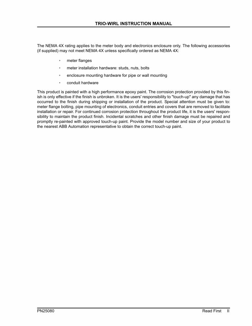
The NEMA 4X rating applies to the meter body and electronics enclosure only. The following accessories(if supplied) may not meet NEMA 4X unless specifically ordered as NEMA 4X:
* meter flanges
* meter installation hardware: studs, nuts, bolts
* enclosure mounting hardware for pipe or wall mounting
* conduit hardware
This product is painted with a high performance epoxy paint. The corrosion protection provided by this fin-ish is only effective if the finish is unbroken. It is the users' responsibility to "touch-up" any damage that hasoccurred to the finish during shipping or installation of the product. Special attention must be given to:meter flange bolting, pipe mounting of electronics, conduit entries and covers that are removed to facilitateinstallation or repair. For continued corrosion protection throughout the product life, it is the users' respon-sibility to maintain the product finish. Incidental scratches and other finish damage must be repaired andpromptly re-painted with approved touch-up paint. Provide the model number and size of your product tothe nearest ABB Automation representative to obtain the correct touch-up paint.
PN25080 Read First II

TRIO-WIRL INSTRUCTION MANUAL
CHAPTER 1 Introduction
1.1 DescriptionThe ABB Inc. TRIO-WIRL family of flowmeters consistsof the TRIO-WIRL V vortex flowmeter and theTRIO-WIRL S swirlmeter. The TRIO-WIRL V is avail-able in two models in either flanged or wafer styles. Acompact or integral Model VT4000 and a remote ModelVR4000. Similarly, the TRIO-WIRL S is available inST4000 and SR4000 models but only in flanged style.
The VT4000 Vortex and ST4000 Swirlmeters are sup-plied with an integrally mounted microprocessor-basedsignal converter using state-of-the-art Digital SignalProcessor (DSP) technology for superior flow andvibration noise immunity. This combination of flowme-ter and electronics allows maximum flexibility foron-site configuration and maintenance. Database inter-rogations and changes at the flowmeter may be per-formed using the three pushbuttons or by activatingthree magnetic switches using a magnetic "stick". The
two line, 16 character LCD display permits continuousmonitoring of the flow rate or other flow parameters.
The flowmeters are suitable for service with gas andliquid processes. The meters’ extended temperaturerange permits accurate metering of saturated andsuperheated steam.
The meter body, sensor and process connections aremade of 316L stainless steel or Hastalloy C. Becausethe meter has no moving parts, routine maintenance orrecalibration is not required.
The TRIO-WIRL model and body style variations areshown in the illustrations below.
Compact or Integral Design: Converter mounted directly on the flowmeter primary
Vortex Flowmeter TRIO-WIRL VTWafer Design
Vortex Flowmeter TRIO-WIRL VTFlanged Design
Swirl Flowmeter TRIO-WIRL STFlanged Design
PN25080 Introduction 1 - 1

TRIO-WIRL INSTRUCTION MANUAL
Remote Mounted Design: The converter remotely mounted up to 10m from the flowmeter primary..
1.2 Features
* No Moving Parts
* Common meter for liquid, gas and steam.
* DSP Converter with state-of-the-art digital filteringtechnology provides immunity to the effects ofhydraulic noise and vibration.
* Selectable operating modes for volumetric or massflow rate.
* Configuration in hazardous areas by magnetic stickwithout removing housing covers.
* Digital Communications using HART®, Profibus orFoundation Fieldbus protocols.
* Common sensor and electronics for all size meters
* Optional integrated PT100 for temperature moni-toring or mass calculations
* High accuracy / wide turndowns
1.3 OrganizationThe remainder of this instruction manual is organizedinto four main sections:
* Swirlmeter (TRIO-WIRL S) Primaries
* Vortex (TRIO-WIRL V) Primaries
* TRIO-WIRL Converter
* Start-Up & Operation
Refer to the appropriate section for your meter fodetails on the following:
* Operating principles
* Assembly & Installation
* Electrical Interconnections
* Start-up Procedures
Vortex Flowmeter TRIO-WIRL VR
Wafer Design
Vortex Flowmeter TRIO-WIRL VRFlanged Design
Swirl Flowmeter TRIO-WIRL SRFlanged Design
Introduction 1 - 2 PN25080
TRIO-WIRL INSTRUCTION MANUAL
CHAPTER 2 Swirlmeter (TRIO-WIRL S)
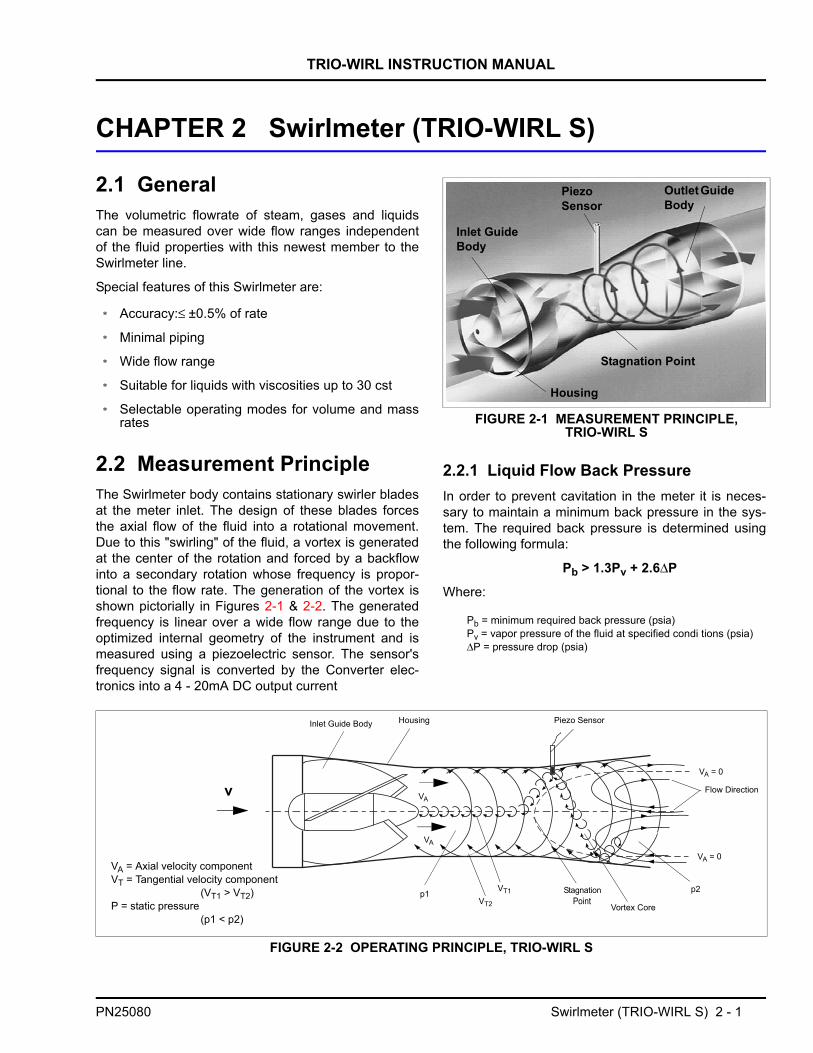
2.1 GeneralThe volumetric flowrate of steam, gases and liquidscan be measured over wide flow ranges independentof the fluid properties with this newest member to theSwirlmeter line.
Special features of this Swirlmeter are:
* Accuracy:≤ ±0.5% of rate
* Minimal piping
* Wide flow range
* Suitable for liquids with viscosities up to 30 cst
* Selectable operating modes for volume and massrates
2.2 Measurement PrincipleThe Swirlmeter body contains stationary swirler bladesat the meter inlet. The design of these blades forcesthe axial flow of the fluid into a rotational movement.Due to this "swirling" of the fluid, a vortex is generatedat the center of the rotation and forced by a backflowinto a secondary rotation whose frequency is propor-tional to the flow rate. The generation of the vortex isshown pictorially in Figures 2-1 & 2-2. The generatedfrequency is linear over a wide flow range due to theoptimized internal geometry of the instrument and ismeasured using a piezoelectric sensor. The sensor'sfrequency signal is converted by the Converter elec-tronics into a 4 - 20mA DC output current
2.2.1 Liquid Flow Back PressureIn order to prevent cavitation in the meter it is neces-sary to maintain a minimum back pressure in the sys-tem. The required back pressure is determined usingthe following formula:
Pb > 1.3Pv + 2.6∆P
Where:
Pb = minimum required back pressure (psia)Pv = vapor pressure of the fluid at specified condi tions (psia)∆P = pressure drop (psia)
FIGURE 2-1 MEASUREMENT PRINCIPLE, TRIO-WIRL S
PiezoSensor
Outlet Guide Body
Inlet Guide Body
Housing
Stagnation Point
FIGURE 2-2 OPERATING PRINCIPLE, TRIO-WIRL S
HousingInlet Guide Body Piezo Sensor
Flow Direction
VA = 0
VA = 0
Vortex Core
p2VT1VT2
p1
v
VA = Axial velocity componentVT = Tangential velocity component
(VT1 > VT2)P = static pressure
(p1 < p2)
VA
VA
StagnationPoint
PN25080 Swirlmeter (TRIO-WIRL S) 2 - 1
TRIO-WIRL INSTRUCTION MANUAL
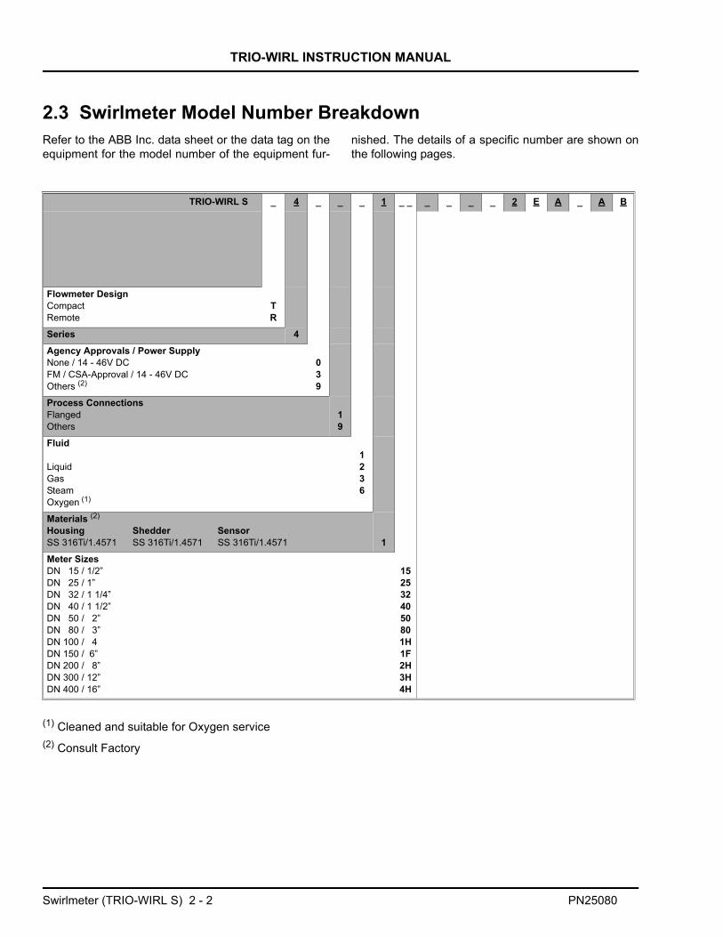
2.3 Swirlmeter Model Number BreakdownRefer to the ABB Inc. data sheet or the data tag on theequipment for the model number of the equipment fur-
nished. The details of a specific number are shown onthe following pages.
(1) Cleaned and suitable for Oxygen service(2) Consult Factory
TRIO-WIRL S _ 4 _ _ _ 1 _ _ _ _ _ _ 2 E A _ A B
Flowmeter DesignCompactRemote
TR
Series 4Agency Approvals / Power SupplyNone / 14 - 46V DCFM / CSA-Approval / 14 - 46V DCOthers (2)
039
Process ConnectionsFlangedOthers
19
Fluid
LiquidGasSteamOxygen (1)
1236
Materials (2)
Housing Shedder SensorSS 316Ti/1.4571 SS 316Ti/1.4571 SS 316Ti/1.4571 1Meter SizesDN 15 / 1/2”DN 25 / 1”DN 32 / 1 1/4”DN 40 / 1 1/2”DN 50 / 2”DN 80 / 3”DN 100 / 4DN 150 / 6”DN 200 / 8”DN 300 / 12”DN 400 / 16”
1525324050801H1F2H3H4H
Swirlmeter (TRIO-WIRL S) 2 - 2 PN25080

TRIO-WIRL INSTRUCTION MANUAL
Swirlmeter Model Number Breakdown (Cont.)
TRIO-WIRL S _ 4 _ _ _ 1 _ _ _ _ _ _ 2 E A _ A B
Pressure RatingANSI CL 150ANSI CL 300ANSI CL 600Other
QRSZ
Sensor DesignStandard, single sensorStandard, single sensor with integr. temperature sensor
12
Temperature Range Fluid/GasketsKalrez O-Ring 32 °F to 536 °F (0 °C to 280 °C)Viton O-Ring -67 °F to 446 °F (-55 °C to 230 °C) (not for steam)PTFE O-Ring -67 °F to 392 °F (-55 °C to 200 °C)
345
CertificatesNoneEN 10204 (DIN 50049-3.1b)
AC
CommunicationWith Display and HART 2Instrument TagEnglish EDesign Level/Software Level BAccessoriesNone2” Pipe mount (only SR)
01
Operating ModeContinuous flowrate ACable Conduit½“ NPT B
PN25080 Swirlmeter (TRIO-WIRL S) 2 - 3

TRIO-WIRL INSTRUCTION MANUAL
2.4 Installation2.4.1 InspectionAll equipment should be inspected for damage thatmay have occurred during shipment. All damageshould be reported to the shipping agent. If the equip-ment is damaged to the extent that faulty operationmay result, contact ABB Inc. before installation. Alwaysreference the complete instrument serial number andmodel number in all correspondence concerning theequipment supplied.
2.4.2 Location & Mounting2.4.2.1 Installation
The Swirlmeter may be installed at virtually any loca-tion in a pipeline. The meter may be installed at anyangle and is available in a flange style body thatmounts between adjacent pipe flanges of the processpiping. Since the meter is unidirectional, it must be ori-ented in accordance with the direction of the processflow. A flow direction arrow is provided on the meterbody to assure correct orientation.
Take care to observe the following guidelines:
* Do not exceed the ambient temperature require-ments
* Observe the recommended inlet and outlet straightsections piping requirements (Refer to Figure 2-3).
* Make sure the flow direction corresponds to thedirection indicated by the arrow on the flowmeterprimary.
* Make sure that the required minimum distance forremoving the converter and exchanging sensors isprovided.
* The inside diameters of the flowmeter primary andthe pipeline should be identical.
* Pressure fluctuations at zero flowrate in long pipe-lines should be eliminated by installing intermedi-ate gate valves.
* Flow pulsations resulting from piston pump or com-pressor operation should be reduced by usingappropriate dampeners.
* When metering liquids, the flowmeter primary mustalways be completely filled with fluid and cannotdrain.
* For high fluid temperatures the flowmeter primaryis installed so that the electronic assembly is
mounted at the side or bottom of the flowmeter(Refer to Figure 2-7).
* If the possibility of gas bubble formation exists, gasseparators should be provided.
* Assuming a properly supported pipeline and theconverter’s DSP signal processing technology,vibration problems should not be encountered innormal industrial applications. However, it is goodpractice to minimize mechanical vibrations usingsupports if required. When installing in long pipe-lines which have a tendency to vibrate, eliminatorsshould be installed upstream and downstream ofthe flowmeter.
* In vertical and sloping installations, the electricalconduit entries should face downward to retard theentry of condensation.
2.4.2.2 Recommended Inlet & Outlet Sections
Due to the measurement principles of the Swirl Flow-meter it can be installed with very minimal inlet and out-let straight section lengths. Strainers and flowstraighteners are not required. Figure 2-3 shows therecommended lengths for the inlet and outlet straightsections for various installation conditions. No inlet andoutlet straight sections are required when single ordouble elbows are installed upstream or downstreamfrom the flowmeter primary when the radius of theelbow is greater than 1.8 x D.
To assure optimum meter performance, the metershould be installed in accordance with the upstreamand downstream straight run piping requirementsshown in Figure 2-3. The straight run piping should beschedule 80 or lighter pipe. Process flanges should beraised face.
Remove the covers used to protect the meter inlet andoutlet surfaces from damage during shipment.
Place the two flange gaskets (supplied) against theupstream and downstream flange faces (Refer to Table7-5 for replacement flange gaskets). Align the gasketholes with the flange hole pattern. When installing theflange gaskets, make sure that the gaskets fit properlyand are alligned properly so that they don't project intothe pipe line causing an alteration of the flow profile. Achange in flow profile can adversely affect meter accu-racy.
Swirlmeter (TRIO-WIRL S) 2 - 4 PN25080

TRIO-WIRL INSTRUCTION MANUAL
Mounting bolts and nuts are supplied by the user.During installation, make certain that the flow directionarrow on the meter body is oriented in accordance withthe process flow.
With the meter safely supported, install the boltsthrough the meter and process flanges. Bolts and nutsshould be lubricated with a graphite based lubricant.Assemble the nuts to the bolts hand tight. Tighten theflange nuts in a diagonal or "star" pattern as shown inFigure 2-4 to equalize pressure on the flange face andgaskets. Bolt/nut torque should be limited to that whichwill provide a leakproof seal.
2.4.2.3 Control Valve Installation
Control valves should preferebly be installed down-stream from the flowmeter as shown in Figure 2-5.
When this is not possible, the control valve should belocated > 3D upstream of the flowmeter.
2.4.2.4 Extreme Temperature Applications
For process temperatures above 160o F (71o C) orbelow 0o F (-18o C), it is critical that the meter be pres-surized and placed into service gradually, i.e., with suf-ficient time delay to minimize thermal shock. Steamshould be introduced gradually so that the meter isbrought up to operating temperature over a ten to fif-teen minute period.
FIGURE 2-3 METER PIPING REQUIREMENTS
FIGURE 2-4 RECOMMENDED FLANGE BOLT TIGHTENING SEQUENCE
Refer to Figure 2.3 3D
FIGURE 2-5 CONTROL VALVE INSTALLATION
PN25080 Swirlmeter (TRIO-WIRL S) 2 - 5

TRIO-WIRL INSTRUCTION MANUAL
INSULATING THE SWIRLMETERThe flowmeter primary can be insulated to a max. thickness of 4 inches (100 mm) [Refer to Figure 2-6].
FLOWMETER PRIMARY INSTALLATIONS FOR FLUID TEMPERATURES > 300o F (150° C)In horizontal installations, when process tempera-tures above 300o F (150o C) are encountered, themeter must be oriented so that the junction box islocated to the side or below meter body, not above.
Refer to Figure 2-7 for an example of the recom-mended high-temperature application orientation.
NOTE: The interrelationship between the fluid andambient temperatures must be considered (Refer toFigure 2-8).
1) Cables suitable for use to 230o F (110°C) can beused for power supply terminals 31 & 32 and contactoutput terminals 41 & 42 without any reduction in thetemperature range specifications. Cables suitable onlyfor temperatures of 175o F (80°C) reduce the tempera-ture range of the flowmeter as shown in Figure 2-8.
WARNINGWHEN THE METER IS USED IN A VERY HIGH OR LOW TEMPERATURE PROCESS, THE TEMPER-
ATURE OF THE METER BODY MAY BE EXTREMELY HOT OR COLD. IF IT IS NECES-SARY TO TOUCH THE SENSOR HOUSING OR METER BODY, INSULATED GLOVES MUST BE
WORN TO PREVENT SERIOUS INJURY.
FIGURE 2-6 INSULATING THE PIPELINE
CAUTIONTHE PIPELINE AND METER BODY MAY BE INSU-LATED BY THE USER UP TO A THICKNESS OF 4 IN. (100 MM) BUT THE METER INTERCONNEC-
TION WIRING BOX AND SENSOR HOUSING TOWER MUST NOT BE INSULATED. AMBIENT
AIR IS REQUIRED TO DISSIPATE HEAT OR COLD BUILD-UP WITHIN THE INTERCONNECTION WIR-
ING BOX.
FIGURE 2-7 ORIENTATION FOR TEMPERATURES >300° F (150° C)
Ambi
ent T
empe
ratu
re [°
C] 1)
Allowable TemperatureRange (only primary)
Side View, Pipline
Installations for
Fluid Temperature
Fluid Temperature [°C]
oF = [1.8 x oC] + 32
-20
FIGURE 2-8 AMBIENT/FLUID TEMPERATURE RELATIONSHIP
Swirlmeter (TRIO-WIRL S) 2 - 6 PN25080

TRIO-WIRL INSTRUCTION MANUAL
2.4.3 Temperature/Pressure MonitoringProvisions for temperature and/or pressure monitoringare the responsibility of the user. The temperature sen-sor should be located a minimum of three pipe diame-ters downstream of the flowmeter. Measurement isfrom the downstream face of the meter.
An option is available for the Swirlmeter for directPt100 temperature measurements. These temperaturemeasurements can be used to monitor the fluid tem-perature or for the measurement of saturated steam inmass units. The pressure tap is located in the Swirlme-ter body as shown in Figure 2-9.
2.5 Swirlmeter Size Selection2.5.1 GasThe maximum required flowrate should not be lessthan 0.5 x QVMAX if possible, but can be set as low as0.15 QVMAX if required
The flowmeter size selection is made using the maxi-mum actual volume flowrate (QV), at operating condi-tions. If the flowrate to be metered is expressed as astandard flowrate (conditions = 14.7 psia, 70ºF) or as amass flowrate, it will be necessary to first convert thesevalues to their equivalent actual volume flowrate atoperating conditions before selecting the most suitableflowmeter size from the Flow Range Table below..
2.5.1.1 QVMIN for Gases with ρ < 0.0749 lb/ft3
The minimum actual volume flowrate QVMIN’ for gaseswith lower densities can be calculated using the follow-ing equations.
Q‘vmin = Qvmin
QVMINMin. volume flowrate from Table 2-1ρ Density at operating conditions lb/ft3
1. Convert standard density(ρs) to operating density (ρ)
2. Convert to actual volume flowrate (QV)
a) Starting from standard flowrate (Qs) to
b) Starting from mass flowrate (Qm) to Qv
3. Dynamic Viscosity, µ (cps) to kinematic viscosity, ν(cst)
FIGURE 2-9 MEASURING PRESSURE
TABLE 2-1. SWIRL FLOW RANGES, AIR
Meter Size Flow Range [acfh] Frequency [Hz] at QvmaxInch DN Qvmin Qvmax
1/2 15 90 565 1900
1 25 180 1770 1200
1-1/4 32 290 4600 1300
1-1/2 40 430 7070 1400
2 50 640 12370 1200
3 80 2120 30020 690
4 100 2350 52980 700
6 150 5500 127140 470
8 200 8830 173050 330
12 300 18720 353150 160
16 400 37090 706300 150
Air at 70 °F, 14.7 psi, ρ = 0.075 lb/ft3
0.0749ρ
----------------
ρ ρs14.7 p+
14.7--------------------× 530
460 T+-------------------×=
QV Qs14.7
14.7 p+-------------------- 460 T+
530-------------------×
ρsρ----- Qs×==
QVQm
ρ----------=
ν µρ---=
PN25080 Swirlmeter (TRIO-WIRL S) 2 - 7

TRIO-WIRL INSTRUCTION MANUAL
ρ = Density at operating conditions [lb/ft3]
ρS = Density at standard conditions [lb/ft3]
p = Pressure at operating conditions [psig]
T = Temperature at operating conditions [°F]
QV = Actual volume flowrate [acfh]
Qs = standard flowrate [scfh]
Qm = Mass flowrate [lb/h]
2.5.1.2 Example for Gases:
Determine the flowmeter size for metering 35,000 scf/h(Qs) carbon dioxide; temp. = 100 °F, press. = 70 psig.
ρs = 0.123 lb/ft3 (CO2, see Table 2-2)
1. Convert ρs to ρ:
2. Convert from Qs (ft3/h) to Qv (ft3/h) :
Refer to Table 2-1 to see that a 1-1/2” / DN 40 meterhas the following flow range: 430 to 7070 acfh
3. Using Figure 2-10, find the pressure drop atQv = 6425 ft3/h and ρ = 0.67 lb/ft3:
2.5.1.3 Pressure Drop, Gas & Steam (psi)
Refer to Figure 2-10 for air ( @70o F, 14.7 psi, ρ=0.075lb/ft3 ). For other fluid densities the pressure drop canbe calculated using the following equation:
∆p’= Fluid pressure drop [psi]
∆p = Air pressure drop (from Figure 2-10) [psi]
ρ = Fluid density [lb/ft3] (at operating conditions)
ρ 0.123 14.7 70+14.7
---------------------- 530460 100+------------------------× 0.67==
Qv 35060 0.1230.67
-------------× 6425acfh= =
p'∆ 0.67··
0.0749---------------- 0.85× 7.6psi= =
TABLE 2-2. STANDARD DENSITIES FOR SELECTED GASES
Gas Standard Density [lb/ft3]
Acetylene 0.0732
Air 0.0749
Ammonia 0.0481
Argon 0.1111
Butane 0.1686
Carbon Dioxide 0.1230
Carbon Monoxide 0.0780
Ethane 0.0843
Ethylene 0.0787
Hydrogen 0.0056
Methane 0.0448
Natural Gas 0.045
Neon 0.0556
Nitrogen 0.0780
Oxygen 0.0893
Propane 0.1261
Propylene 0.1196
∆p' ρ0.075------------- ∆p×=
lb/ft3
Swirlmeter (TRIO-WIRL S) 2 - 8 PN25080

TRIO-WIRL INSTRUCTION MANUAL
FIGURE 2-10 PRESSURE DROP, AIR ( @70O F, 14.7 PSI, Ρ=0.075 LB/FT3 )
∆p [p
si]
Qv [ ft3/h ]
PN25080 Swirlmeter (TRIO-WIRL S) 2 - 9

TRIO-WIRL INSTRUCTION MANUAL
2.5.2 LiquidThe maximum required flowrate should not be lessthan 0.5 x Qvmax if possible, but can be set as low as0.15 Qvmax if required.
1. Convert mass flowrate Qm to actual volume flowrate Qv:
ρ = Operating density [lb/ft3]
QV = Actual volume flowrate [ft3/h]
Qm = Mass flowrate [lb/h]
2. Pressure Drop [psi]
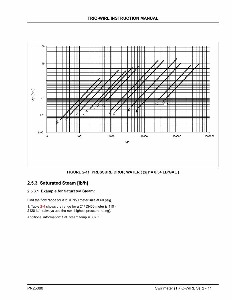
See Figure 2-11 for water (ρ= 8.34 lb/gal)
For other fluid densities the pressure drop can be cal-culated using the following equation:
∆p’= Pressure drop fluid [psi]
∆p = Pressure drop water [psi] (from Figure 2-11)
ρ = Fluid density [lb/gal] (at operating conditions)
3. Static Pressure
To prevent cavitation when metering liquids a positivestatic pressure (back pressure) is required. Its valuecan be estimated using the following equation:
p2 ≥ (1.3 x pVapor) + (2.6 x ∆p`)
p2 = Positive downstream static pressure [psia]
pVapor =Fluid vapor pressure at operating temperature[psia]
∆p` =Fluid pressure drop [psia]
2.5.2.1 Example for Liquids:
Determine the flowmeter size and pressure drop formetering 18000 gph liquid with a density of 7.50 lb/gal.
1. Refer to Table 2-3 to see 3”/ DN 80 meter has arange of 1320 - 26400 gph
2. Using Figure 2-11, find pressure drop at Qv =18000 gph and ρ = 7.50 lb/gal
∆ρ` = psi = 6.3 psi
TABLE 2-3. SWIRL FLOW RANGES, LIQUID
Meter Size Flow RangeGPH
Frequency at QVmax [Hz]
Re minInch DN Qvmin Qvmax1/2 15 30 420 185 21001 25 120 1560 135 52001-1/4 32 240 2640 107 76001-1/2 40 420 4200 110 135002 50 660 6600 90 173003 80 1320 26400 78 150004 100 2100 39600 77 175006 150 4740 97800 50 350008 200 6600 132000 30 4400012 300 26400 264000 16 11800016 400 47400 475500 13 160000
QVQm
ρ----------=
∆p' ρ8.34---------- ∆p×=
7.58.34---------- 7⋅
Swirlmeter (TRIO-WIRL S) 2 - 10 PN25080
TRIO-WIRL INSTRUCTION MANUAL
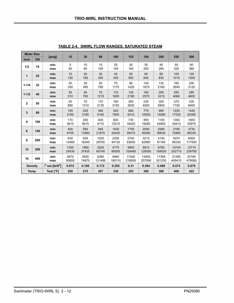
2.5.3 Saturated Steam [lb/h]2.5.3.1 Example for Saturated Steam:
Find the flow range for a 2” /DN50 meter size at 60 psig.
1. Table 2-4 shows the range for a 2” / DN50 meter is 110 - 2120 lb/h (always use the next highest pressure rating).
Additional information: Sat. steam temp.= 307 °F
FIGURE 2-11 PRESSURE DROP, WATER ( @ Ρ = 8.34 LB/GAL )
∆p [p
si]
16"
PN25080 Swirlmeter (TRIO-WIRL S) 2 - 11
TRIO-WIRL INSTRUCTION MANUAL
TABLE 2-4. SWIRL FLOW RANGES, SATURATED STEAM
Meter Size[psig] 15 30 60 100 125 150 200 250 300
Inch DN
1/2 15 minmax
540
1060
15100
25145
30145
35205
45265
55325
60385
1 25 minmax
15130
20190
30305
45455
55550
65645
85830
1051015
1251205
1-1/4 32 minmax
20330
30490
50790
751175
901425
1051675
1352160
1652640
2003125
1-1/2 40 minmax
30510
45750
751215
1101805
1352190
1602575
2053315
2504060
2954800
2 50 minmax
45890
701310
1102130
1653155
2003830
2354505
3005805
3707100
4358400
3 80 minmax
1552160
2253185
3655165
5407655
6609310
77510930
99514080
122017230
144020385
4 100 minmax
1703815
2505615
4059115
60013510
73016425
85519285
110524850
135030410
160035975
6 150 minmax
4009155
58513480
94521870
140532420
170539415
200546280
258059630
316072980
373586330
8 200 minmax
63512460
93518345
152029765
225544130
274053650
321562990
414081160
507099330
6000117500
12 300 minmax
135025430
198537435
322060745
477590055
5805109480
6815128550
8780165630
10745202710
12710239790
16 400 minmax
267050855
393574870
6380121485
9460180110
11500218955
13500257095
17395331255
21290405415
25185479580
Density sat [lb/ft3] 0.072 0.106 0.172 0.255 0.31 0.364 0.469 0.574 0.679Temp. Tsat [°F] 250 275 307 338 353 366 388 406 422
ρ
Swirlmeter (TRIO-WIRL S) 2 - 12 PN25080

TRIO-WIRL INSTRUCTION MANUAL
2.6 Specifications2.6.1 Model Overview
MODEL
AccuracyLiquids ≤ ± 0.5 % of rate
Gases and Steam ≤ ± 0.5 % of rate
Reproducibility ≤ ± 0.2 % of rate
Allowable viscosity for liquids to 2”/DN50 ≤ 10 cps
≥ 3”/DN80 ≤ 30 cps
Typical flow range 1:18
Typical up-/downstream straight lengths 3 x D / 1 x D
Flowmeter Primary
Process Connections Flanges (DIN, ANSI. JIS) 1/2”-16”/DN15-DN400
Sensor Design Single sensor YES, optional with integrated temperature measurement
Fluid Temperature Standard -67 °F to 536 °F
Protection Class NEMA 4X (IP67)
Materials
Sensor 316Ti/1.4571 or Hast C
Inlet/Outlet Body Guide 1.4571 opt. Hast. C
Meter Housing 316Ti/1.4571/CF3M or Hast C
Sensor Gasket Kalrez, Viton, PTFE
Approvals / Certifications
Intrinsically Safe &Explosion-Proof Design FM / CSA Approved
Explosion-Proof Class I; Division 1; Groups B-DIntrinsically Safe Class I; Division 1; Groups A-D
Non-Incendive for Class I; Division 2; Groups A-DDust Ignition Proof Class II; Division 1; Groups E-G
ST4000 SR4000
PN25080 Swirlmeter (TRIO-WIRL S) 2 - 13

TRIO-WIRL INSTRUCTION MANUAL
2.6.2 Detailed SpecificationsACCURACY & REPRODUCIBILITY OF FLOW MEASUREMENT
Accuracy (incl. converter): < ± 0.5% of rate(at reference conditions)
Reproducibility: < 0.2% of rate
ACCURACY & REPRODUCIBILITY OF THE TEMPERATURE MEASUREMENT
Accuracy (incl. converter): ≤ ±2ºC / ≤ ± 3.6ºFReproducibility: < 0.2% of rate
OVERRANGE:Gases: 15% over maximum flowrateLiquids: 15% over maximum flowrate
Note: Cavitation may not occur.
OPERATING PRESSURE:Flanged Design: ANSI CL 150/300/600, options to CL 900
CONNECTIONS:Process Connections: Flanges per ANSI or other upon
request
Electrical Connections: Screw terminals, Connector NPT 1/2”(w/o cable connector)
PROTECTION CLASS: NEMA 4X (IP67)
MATERIALS:Housing: SS 316
Option: Hastelloy-C
Flanges: SS 316 Ti/No. 1.4571, Option: Hastelloy-C
In-Outlet Guide Body: SS 316 Ti/No. 1.4571Option: Hastelloy-C
Sensor: SS 316 Ti/No. 1.4571, Option: Hastelloy-C
Sensor Gaskets:
Kalrez O-ring: 32oF to 536oF (0oC to 280oC)Viton O-ring: -67oF to 446oF (-55oC to 230oC)PTFE O-ring: -67oF to 392oF (-55oC to 200oC)
Converter Housing: Cast Aluminum, painted.
WEIGHTS:Refer to the dimensional outline drawing (Figure 2-14)
FLUID TEMPERATURE: - 67oF to 536oF (-55oC to +280oC) (Standard)
Allowable temperature range for the gasket material must beconsidered. The flange gaskets supplied with the meter areKLINGERsil material. These gaskets are rated to a temperatureof 536 oF (280 oC) for liquid applications and 450 oF (232 oC)for gas & steam applications, at internal pressures of 400 psimax.
AMBIENT CONDITIONS:Climate Resistance (per DIN 40040): GSGRelative humidity: 95% Max.
100% with cover in place
AMBIENT TEMPERATURE:-4oF ( -20oC ) to 158oF ( 70oC )
Swirlmeter (TRIO-WIRL S) 2 - 14 PN25080
TRIO-WIRL INSTRUCTION MANUAL
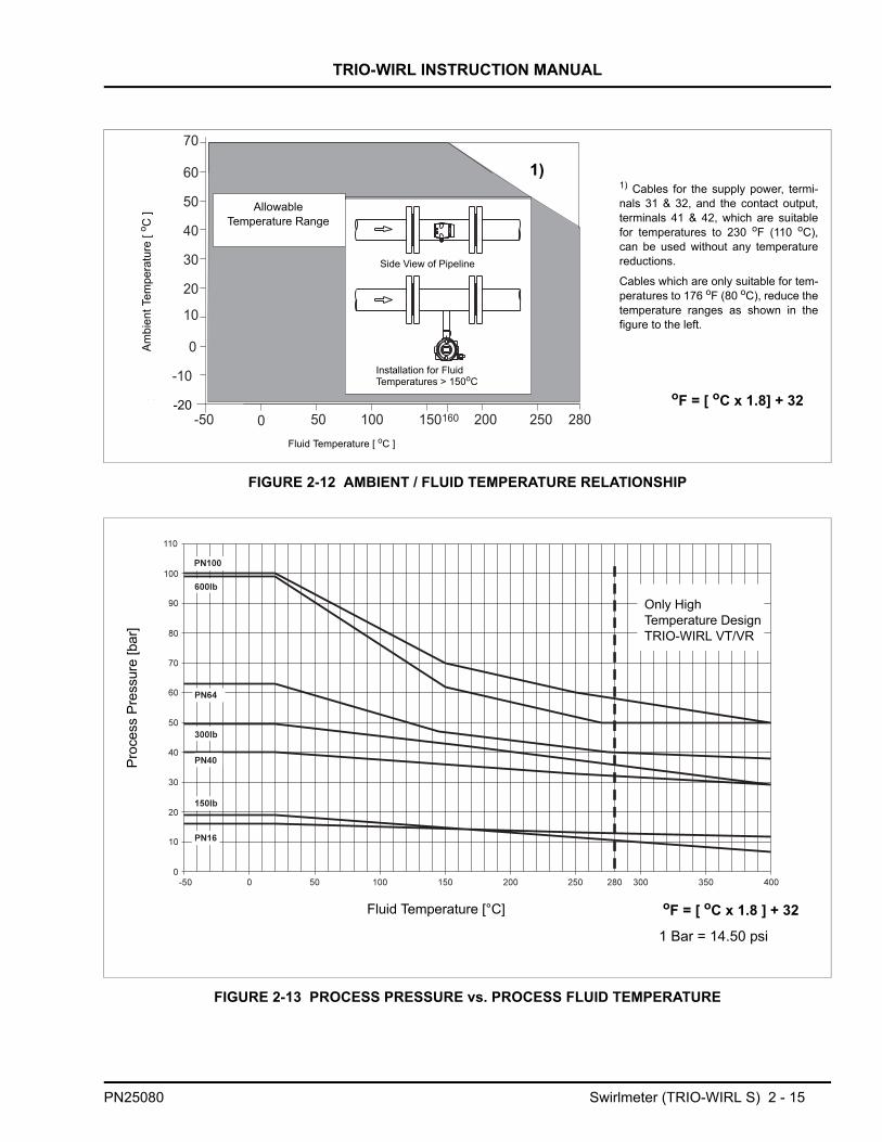
FIGURE 2-12 AMBIENT / FLUID TEMPERATURE RELATIONSHIP
FIGURE 2-13 PROCESS PRESSURE vs. PROCESS FLUID TEMPERATURE
1)
AllowableTemperature Range
Side View of Pipeline
Installation for FluidTemperatures > 150oC
Fluid Temperature [ oC ]
-20
Ambi
ent T
empe
ratu
re [
o C ]
Fluid Temperature [°C]
Proc
ess
Pres
sure
[bar
]
Only High Temperature DesignTRIO-WIRL VT/VR
oF = [ oC x 1.8 ] + 32
1 Bar = 14.50 psi
1) Cables for the supply power, termi-nals 31 & 32, and the contact output,terminals 41 & 42, which are suitablefor temperatures to 230 oF (110 oC),can be used without any temperaturereductions.
Cables which are only suitable for tem-peratures to 176 oF (80 oC), reduce thetemperature ranges as shown in thefigure to the left.
oF = [ oC x 1.8] + 32
PN25080 Swirlmeter (TRIO-WIRL S) 2 - 15

Swirlm
eter
TRIO
-WIR
L INSTR
UC
TION
MA
NU
AL
REF. OD-10-2829_r0
(TRIO
-WIR
L S) 2 - 16
PN25080
FIGU
RE 2-14 O
UTLIN
E DIM
ENSIO
NS, ST/SR
PRIM
AR
Y

TRIO-WIRL INSTRUCTION MANUAL
CHAPTER 3 Vortex Meter (TRIO-WIRL V)
3.1 GeneralThe volumetric flowrate of steam, gases and liquidscan be measured over wide flow ranges independentof the fluid properties with this newest member to theVortex Meter line.
Special features of this Vortex meter are:
* Accuracy: Liquids: ≤ ±0.75% of rateGas/Steam: ≤ ±1% of rate
* Rugged and simple flowmeter primary design.
* Wafer design.
* High temperature design to 400ºC (750ºF).
* High pressure design to ANSI CL 900.
* operating modes for volume and mass rate
3.2 Measurement PrincipleThe operation of the TRIO-WIRL V vortex meter isbased on the Karman Vortex Street. Vortices areformed as the fluid flows around a shedder body.These vortices are alternately shed from the sides ofthe shedder body. The fluid flow causes these vorticesto be released forming a "vortex street" (Karman VortexStreet), refer to Figures 3-1 & 3-3.
The frequency f of the vortex shedding is proportionalto the flow velocity v and inversely proportional to thewidth of the shedder body d:
The quality of the vortex flowrate measurements isdetermined by the dimensionless Strouhal Number(St). By appropriate design of the shedder body, St isconstant over a wide Reynolds Number (Re) range asshown in Figure 3-2.
As a result, the vortex shedding frequency to be evalu-ated, is only a function of the flow velocity and is inde-pendent of the fluid density and viscosity.
The local pressure changes resulting from the vortexshedding are detected by a Piezo sensor and con-verted into electrical pulses corresponding to the vortexshedding frequency. The flowrate proportional fre-quency signal generated in the flowmeter primary isprocessed in the converter into a current output (4 - 20mA) signal.
Figure 3-3 shows a cross-sectional view of the KarmanVortex Street and the generated vortices.
FIGURE 3-1 FLOW MEASUREMENT PRINCIPLE, TRIO-WIRL V
Shedder Body
PiezoSensor
FIGURE 3-2 STROUHAL NUMBER / REYNOLDS NUMBER RELATIONSHIP
f St vd---×=
Re v D×µ
-------------= = Kinematic viscosity
D = Meter tube diameterv = Flow Velocity
µ
PN25080 Vortex Meter (TRIO-WIRL V) 3 - 1

TRIO-WIRL INSTRUCTION MANUAL
FIGURE 3-3 OPERATING PRINCIPLE, TRIO-WIRL V
SHEDDER PIEZO-SENSOR(Option: with PT100)
Vortex Meter (TRIO-WIRL V) 3 - 2 PN25080

TRIO-WIRL INSTRUCTION MANUAL
3.3 Vortex Model Number BreakdownRefer to the ABB Inc. data sheet or the data tag on theequipment for the model number of the equipment fur-
nished. The details of a specific number are shown onthe following pages.
(1) Cleaned and suitable for Oxygen service(2) Consult Factory
TRIO-WIRL V _ 4 _ _ _ _ _ _ _ _ _ _ _ E A _ A B
Flowmeter DesignCompactRemote
TR
Series 4
Agency Approvals / Power SupplyNone / 14 - 46V DCFM / CSA-Approval / 14 - 46V DCOthers (2)
039
Process ConnectionsFlangedWaferOthers
139
FluidLiquidGasSteamOxygen (1)
1236
Materials Housing Shedder SensorSS 316Ti/1.4571 SS 316Ti/1.4571 SS 316Ti/1.4571Hastalloy C Hastalloy C Hastalloy C
13
Meter SizesDN 15 / 1/2”DN 25 / 1”DN 40 / 1 1/2”DN 50 / 2”DN 80 / 3”DN 100 / 4DN 150 / 6”DN 200 / 8”DN 250 / 10”DN 300 / 12”
15254050801H1F2H2F3H
PN25080 Vortex Meter (TRIO-WIRL V) 3 - 3

TRIO-WIRL INSTRUCTION MANUAL
Vortex Model Number Breakdown (Cont.)
(1) Cleaned and suitable for Oxygen service(2) Consult Factory
TRIO-WIRL V _ 4 _ _ _ _ _ _ _ _ _ _ _ E A _ A B
Pressure RatingANSI CL 150ANSI CL 300ANSI CL 600 (2)
Other
QRSZ
Sensor DesignStandard sensorStandard sensor with integral temperature sensorHigh Temperature [<750oF (400oC)] sensor (2)
125
Temperature Range Fluid/GasketsGraphite -67 °F to 536 °F (-55 °C to 280 °C) (2)
Graphite Special -67 °F to 750 °F (-55 °C to 400 °C) (2)
Kalrez O-Ring 32 °F to 536 °F (0 °C to 280 °C)Viton O-Ring -67 °F to 446 °F (-55 °C to 230 °C) (not for steam)PTFE O-Ring -67 °F to 392 °F (-55 °C to 200 °C)
12345
CertificatesNoneEN 10204 (DIN 50049-3.1b)
AC
CommunicationWith Display and HART 2
Instrument TagEnglish E
Design Level/Software Level B
AccessoriesNone2” Pipe Mount (only VR)
01
Operating ModeContinuous flowrate A
Cable Conduit½“ NPT B
Vortex Meter (TRIO-WIRL V) 3 - 4 PN25080
TRIO-WIRL INSTRUCTION MANUAL
3.4 Installation3.4.1 InspectionAll equipment should be inspected for damage thatmay have occurred during shipment. All damageshould be reported to the shipping agent. If the equip-ment is damaged to the extent that faulty operationmay result, contact ABB Inc. before installation. Alwaysreference the complete instrument serial number andmodel number in all correspondence concerning theequipment supplied.
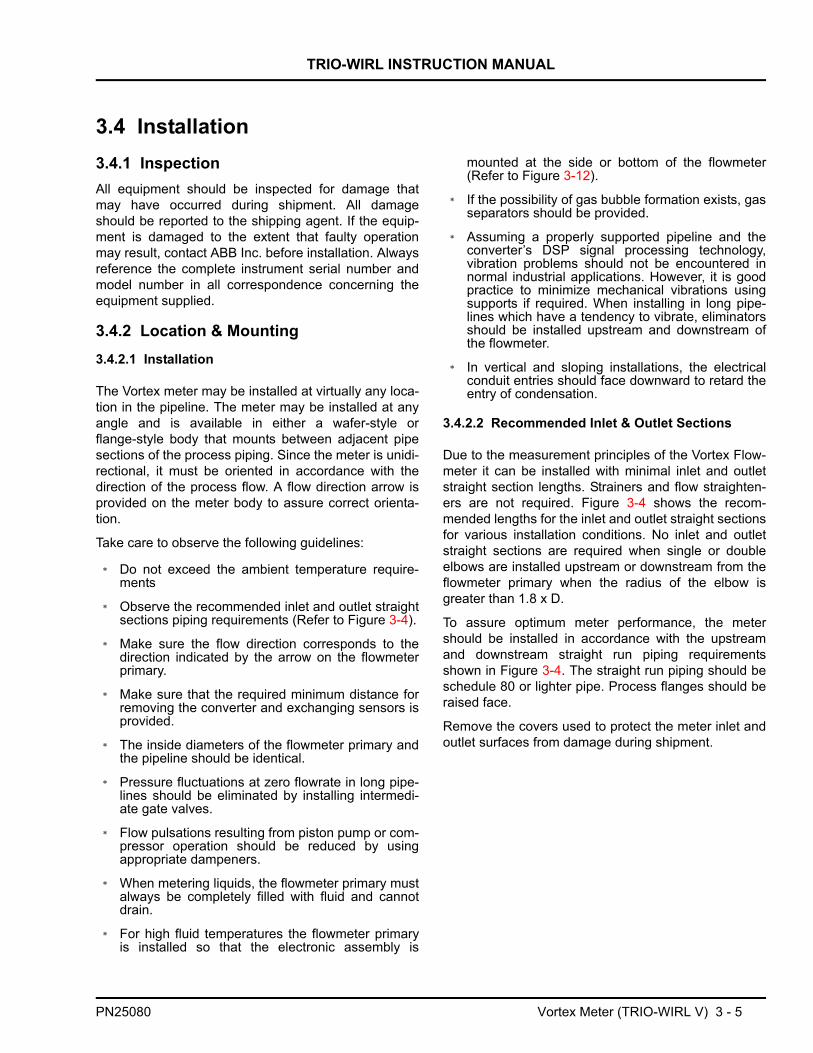
3.4.2 Location & Mounting3.4.2.1 Installation
The Vortex meter may be installed at virtually any loca-tion in the pipeline. The meter may be installed at anyangle and is available in either a wafer-style orflange-style body that mounts between adjacent pipesections of the process piping. Since the meter is unidi-rectional, it must be oriented in accordance with thedirection of the process flow. A flow direction arrow isprovided on the meter body to assure correct orienta-tion.
Take care to observe the following guidelines:
* Do not exceed the ambient temperature require-ments
* Observe the recommended inlet and outlet straightsections piping requirements (Refer to Figure 3-4).
* Make sure the flow direction corresponds to thedirection indicated by the arrow on the flowmeterprimary.
* Make sure that the required minimum distance forremoving the converter and exchanging sensors isprovided.
* The inside diameters of the flowmeter primary andthe pipeline should be identical.
* Pressure fluctuations at zero flowrate in long pipe-lines should be eliminated by installing intermedi-ate gate valves.
* Flow pulsations resulting from piston pump or com-pressor operation should be reduced by usingappropriate dampeners.
* When metering liquids, the flowmeter primary mustalways be completely filled with fluid and cannotdrain.
* For high fluid temperatures the flowmeter primaryis installed so that the electronic assembly is
mounted at the side or bottom of the flowmeter(Refer to Figure 3-12).
* If the possibility of gas bubble formation exists, gasseparators should be provided.
* Assuming a properly supported pipeline and theconverter’s DSP signal processing technology,vibration problems should not be encountered innormal industrial applications. However, it is goodpractice to minimize mechanical vibrations usingsupports if required. When installing in long pipe-lines which have a tendency to vibrate, eliminatorsshould be installed upstream and downstream ofthe flowmeter.
* In vertical and sloping installations, the electricalconduit entries should face downward to retard theentry of condensation.
3.4.2.2 Recommended Inlet & Outlet Sections
Due to the measurement principles of the Vortex Flow-meter it can be installed with minimal inlet and outletstraight section lengths. Strainers and flow straighten-ers are not required. Figure 3-4 shows the recom-mended lengths for the inlet and outlet straight sectionsfor various installation conditions. No inlet and outletstraight sections are required when single or doubleelbows are installed upstream or downstream from theflowmeter primary when the radius of the elbow isgreater than 1.8 x D.
To assure optimum meter performance, the metershould be installed in accordance with the upstreamand downstream straight run piping requirementsshown in Figure 3-4. The straight run piping should beschedule 80 or lighter pipe. Process flanges should beraised face.
Remove the covers used to protect the meter inlet andoutlet surfaces from damage during shipment.
PN25080 Vortex Meter (TRIO-WIRL V) 3 - 5

TRIO-WIRL INSTRUCTION MANUAL
centering devices 3.4.2.3 Wafer-Style Installation
The wafer type meter body mounts inside the pipeflange bolt circle and ranges in size from 1/2 to 8inches. To assure optimum meter performance, themeter should be installed in accordance with theupstream and downstream straight run piping require-ments given in Figure 3-4. The straight run pipingshould be schedule 80 or lighter pipe. Either flat orraised face flanges may be used.
Remove the shipping covers used to protect the meterinlet and outlet surfaces from damage during transitand handling.
WAFER STYLE, SIZES 1 THROUGH 2 INCHES Optional centering devices, mounting studs and nuts(Refer to Tables 7-3 & 7-4 for replacement parts) aresupplied when specified at time of order. The centeringdevices have an internal diameter that permits the ringto be mounted via an undercut face on the inlet andoutlet ends of the meter body. Regardless of whetherthe meter will be installed in a horizontal, sloping, orvertical pipeline, one ring is used at the inlet end andthe other ring at the outlet end of the meter. Use of thecentering devices is illustrated in Figure 3-5. The ringswill have several bolt alignment hole patterns that arespaced and located on different bolt circle radii. Thispermits the centering device for a particular meter sizeto be adapted for various flange ratings, e.g., ANSIClass 150, 300 or 600 lb. flanges. When installing thecentering devices, orient them so that the flange ratingvalues stamped on the rings will face the meter body,i.e., markings must be visible. Position the centeringdevice so that the mounting studs will pass through theappropriate set of bolt circle radii, as designatedaccording to the flange rating.
Place the two flange gaskets (supplied) against theupstream and downstream flange faces (Refer to Table7-5 for replacement flange gaskets). Align the gasketsholes with the flange bolt pattern. When installing theflange gaskets, use care to assure that the gaskets fitproperly and do not project into the pipe line causing analteration of the flow profile. A change in flow profilecan adversely affect meter accuracy.
Install the meter in the pipeline, between the inlet andoutlet gaskets. Make certain that the flow directionarrow on the meter body is oriented in accordance withthe process flow. If the meter is installed in a horizontalpipeline, insert two studs in the bottom two flange holesto support the meter. When installing the meter in avertical pipe run, some temporary support may berequired until mounting studs and nuts have beeninstalled.FIGURE 3-4 METER PIPING REQUIREMENTS
Vortex Meter (TRIO-WIRL V) 3 - 6 PN25080

TRIO-WIRL INSTRUCTION MANUAL
Install the remaining mounting studs, as required.Studs and nuts should be lubricated with a graphitebased lubricant. Assemble a nut on each end of themounting studs hand tight. Tighten the stud nuts in a
diagonally opposite pattern, as shown in Figure 3-8, toequalize pressure on the meter face. Nut torque shouldbe limited to that which will provide a leakproof seal.
WAFER STYLE, SIZES 3 THROUGH 8 INCHESPlace the two flange gaskets (supplied) against theupstream and downstream flange faces (Refer to Table7-5 for replacement flange gaskets). Align the gasketsholes with the flange bolt pattern. When installing theflange gaskets, use care to assure that the gaskets fitproperly and do not project into the pipe line causing analteration of the flow profile. A change in flow profilecan adversely affect meter accuracy.
Optional centering sleeves (spacers), mounting studsand nuts are supplied (Refer to Tables 7-3 & 7-4 forreplacement parts) when specified at time of order.
Placement of the sleeves is dependent on the type ofinstallation (vertical/horizontal/sloping). If the meter isinstalled in a vertical pipeline, select four equallyspaced bolt holes for placement of the four sleeves andstuds (refer to Figure 3-6). If the meter is installed in a
horizontal or sloping pipeline, select the bottom twoholes of the flanges on each end of the meter for place-ment of the four sleeves and studs.
Install the meter in the pipeline between the inlet andoutlet gaskets. Make certain that the flow directionarrow on the meter body is oriented in accordance withthe process flow. In horizontal pipe runs the meter willbe supported by the upstream and downstreamsleeves. When installing the meter in a vertical piperun, some temporary support may be required untilmounting studs and nuts have been installed.
Install the remaining mounting studs, as required.Studs and nuts should be lubricated with a graphitebased lubricant. Place a hex nut on each end of themounting stud. Tighten the stud nuts in a diagonallyopposite pattern, as shown in Figure 3-8, to equalizepressure on the meter face. Nut torque should be lim-ited to that which will provide a leakproof seal.
FIGURE 3-5 WAFER PROCESS CONNECTIONS, SIZES 1/2 THROUGH 2 INCHES
PN25080 Vortex Meter (TRIO-WIRL V) 3 - 7
TRIO-WIRL INSTRUCTION MANUAL
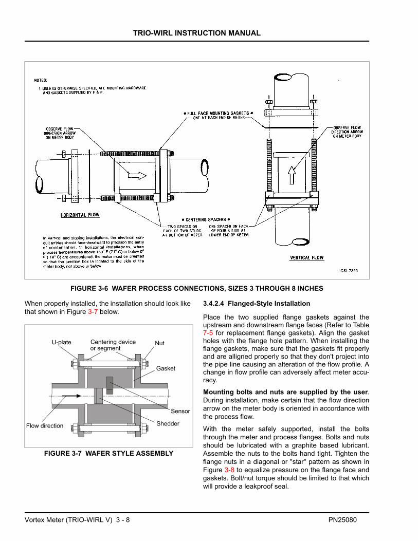
When properly installed, the installation should look likethat shown in Figure 3-7 below.
3.4.2.4 Flanged-Style Installation
Place the two supplied flange gaskets against theupstream and downstream flange faces (Refer to Table7-5 for replacement flange gaskets). Align the gasketholes with the flange hole pattern. When installing theflange gaskets, make sure that the gaskets fit properlyand are alligned properly so that they don't project intothe pipe line causing an alteration of the flow profile. Achange in flow profile can adversely affect meter accu-racy.
Mounting bolts and nuts are supplied by the user.During installation, make certain that the flow directionarrow on the meter body is oriented in accordance withthe process flow.
With the meter safely supported, install the boltsthrough the meter and process flanges. Bolts and nutsshould be lubricated with a graphite based lubricant.Assemble the nuts to the bolts hand tight. Tighten theflange nuts in a diagonal or "star" pattern as shown inFigure 3-8 to equalize pressure on the flange face andgaskets. Bolt/nut torque should be limited to that whichwill provide a leakproof seal.
FIGURE 3-6 WAFER PROCESS CONNECTIONS, SIZES 3 THROUGH 8 INCHES
FIGURE 3-7 WAFER STYLE ASSEMBLY
U-plate Centering deviceor segment
Nut
Gasket
Sensor
ShedderFlow direction
Vortex Meter (TRIO-WIRL V) 3 - 8 PN25080
TRIO-WIRL INSTRUCTION MANUAL
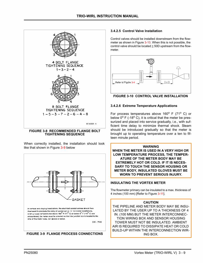
When correctly installed, the installation should looklike that shown in Figure 3-9 below
3.4.2.5 Control Valve Installation
Control valves should be installed downstream from the flow-meter as shown in Figure 3-10. When this is not possible, the control valve should be located > 50D upstream from the flow-meter.
3.4.2.6 Extreme Temperature Applications
For process temperatures above 160o F (71o C) orbelow 0o F (-18o C), it is critical that the meter be pres-surized and placed into service gradually, i.e., with suf-ficient time delay to minimize thermal shock. Steamshould be introduced gradually so that the meter isbrought up to operating temperature over a ten to fif-teen minute period.
INSULATING THE VORTEX METER
The flowmeter primary can be insulated to a max. thickness of 4 inches (100 mm) [Refer to Figure 3-11].
FIGURE 3-8 RECOMMENDED FLANGE BOLT TIGHTENING SEQUENCE
FIGURE 3-9 FLANGE PROCESS CONNECTIONS
WARNINGWHEN THE METER IS USED IN A VERY HIGH OR LOW TEMPERATURE PROCESS, THE TEMPER-
ATURE OF THE METER BODY MAY BE EXTREMELY HOT OR COLD. IF IT IS NECES-SARY TO TOUCH THE SENSOR HOUSING OR METER BODY, INSULATED GLOVES MUST BE
WORN TO PREVENT SERIOUS INJURY.
CAUTIONTHE PIPELINE AND METER BODY MAY BE INSU-LATED BY THE USER UP TO A THICKNESS OF 4 IN. (100 MM) BUT THE METER INTERCONNEC-
TION WIRING BOX AND SENSOR HOUSING TOWER MUST NOT BE INSULATED. AMBIENT
AIR IS REQUIRED TO DISSIPATE HEAT OR COLD BUILD-UP WITHIN THE INTERCONNECTION WIR-
ING BOX.
Refer to Figure 3-4
FIGURE 3-10 CONTROL VALVE INSTALLATION
PN25080 Vortex Meter (TRIO-WIRL V) 3 - 9

TRIO-WIRL INSTRUCTION MANUAL
FLOWMETER PRIMARY INSTALLATIONS FORFLUID TEMPERATURES > 300o F (150° C)
In horizontal installations, when process tempera-tures above 300o F (150o C) are encountered, themeter must be oriented so that the junction box islocated to the side or below meter body, not above.
Refer to Figure 3-12 for an example of the recom-mended high-temperature application orientation..
When operating at elevated temperatures, the interre-lationship between the fluid and ambient temperaturesmust be taken into consideration. Figure 3-13 showsthe allowable operating range for ambient vs. processfluid temperatures.
1) Cables suitable 230o F (110°C) can be used for the power supplyterminals 31, 32 and the contact output terminals 41, 42 without anyreduction in the temperature range specifications. Cables suitableonly for temperatures of 175o F (80°C) reduce the temperature rangeof the flowmeter as shown in Figure 3-13.
3.4.3 Temperature/Pressure MonitoringProvisions for temperature and/or pressure monitoringare the responsibility of the user. The temperature sen-sor should be located five to eight pipe diametersdownstream of the flowmeter. Measurement is from thedownstream face of the meter. The pressure tap shouldbe located three to five pipe diameters downstream ofthe flowmeter. Measurement is from the downstreamface of the meter.
An option is available for the vortex meter for directPt100 temperature measurements. These temperaturemeasurements can be used to monitor the fluid tem-perature or for the measurement of saturated steam inmass units.
FIGURE 3-11 INSULATING THE PIPELINE
FIGURE 3-12 Orientation for Temperatures >300° F (150o C)
Fluid Temperature [°C]
Ambi
ent T
empe
ratu
re [o C
]
1)
AllowableTemperature Range HT-Design
≤ 400°Cfor Std. Design(≤ 280°C) Side View, Pipeline
Installation forFluid Temperatures > 150°C
-20
FIGURE 3-13 AMBIENT/FLUID TEMPERATURE RELATIONSHIP
Vortex Meter (TRIO-WIRL V) 3 - 10 PN25080

TRIO-WIRL INSTRUCTION MANUAL
3.5 Vortex Meter Size SelectionThe maximum required actual volume flowrate QV atoperating conditions is the basis for the flowmeter sizeselections. In order to utilize the maximum flow rangethis value should not be less than one half of the maxi-mum flowrate for the meter size (QVmax). The linearflow range (see Accuracy Specifications) correspondsto the Reynolds Number (Re) range from 20,000 (or40,000 for 6” / DN 150) to 7,000,000.
If the flowrate to be metered is expressed as a stan-dard flowrate (70 oF, 14.7 psia) or as a mass flowrate, itwill be necessary to first convert these values to theirequivalent actual volume flowrate at operating condi-tions before selecting the most suitable flowmeter sizefrom the Flow Range Tables (Tables 3-1 & 3-4 to 3-6).
1. Convert standard density (ρs) to operating den-sity (ρ).
2. Convert to actual volume flowrate (QV).
a) Starting from standard flowrate (Qs) :
b) Starting from mass flowrate (Qm) :
3. Dynamic viscosity, µ (cps) to kinematicviscosity, ν (cst)
4. Reynolds Number (Re)
Where:
ρ = Density at operating conditions (lb/ft3)ρS = Density at standard conditions (lb/ft3)p = Pressure at operating conditions (psig)T = Temperature at operating conditions (ºF)QV = Actual volume flowrate (acfh)QS = Standard flowrate (scfh)Qm = Mass flowrate (lb/hr)
3.5.1 Gas
ρ ρs14.7 p+
14.7--------------------× 530
460 T+-------------------×=
Qv Qsρsρ----- Q= s
14.714.7 p+-------------------- 460 T+
530-------------------×
=
QvQmρ
--------=
ν µρ---=
Re3160 gpm×
ν------------------------------=
TABLE 3-1. VORTEX FLOW RANGES, AIR
Meter Size Flow Range [acfh] Frequency [Hz]
at QvmaxInch DN Qvmin Qvmax
1/2 15 180 780 1840
1 25 425 2900 1825
1-1/2 40 740 12000 2000
2 50 1500 15900 1250
3 80 2750 33500 760
4 100 4240 63500 650
6 150 9200 143000 425
8 200 14800 240000 310
10 250 29000 424000 235
12 300 45900 600000 190
Air at 70 °F, 14.7 psi, ρ = 0.075 lb/ft3
TABLE 3-2. STANDARD DENSITIES FOR SELECTED GASES
Gas Standard Density [lb/ft3]Acetylene 0.0732Air 0.0749Ammonia 0.0481Argon 0.1111Butane 0.1686Carbon Dioxide 0.1230Carbon Monoxide 0.0780Ethane 0.0843Ethylene 0.0787Hydrogen 0.0056Methane 0.0448Natural Gas 0.045Neon 0.0556Nitrogen 0.0780Oxygen 0.0893Propane 0.1261Propylene 0.1196
PN25080 Vortex Meter (TRIO-WIRL V) 3 - 11

TRIO-WIRL INSTRUCTION MANUAL
1 Valid for 0.03 < Density < 0.08. Consult factory for densities < 0.03 lb/ft3.
3.5.1.1 Example for Gases:
Determine the flowmeter size for metering 98,700 scfh(QS) CO2; temperature 185 oF, pressure = 72 psia.Refer to Section 3.5 for equations.
ρS = 0.1149 lb/ft3 (CO2) (From Table 3-2)
1. Convert ρS to ρ :
=0.46 lb/ft3
2. Convert Qs to Qv:
Select 3 in. meter size (Qvmax = 33,500 acfh). Refer toTable 3-1.
3. Pressure drop at ρ = 0.462 lb/ft3 :
Qv = 24,653 acfh
4. Range start value at ρ = 0.46 lb/ft3 (see Table 3-3)
QVmin = 1138 acfh
3.5.1.2 Pressure Drop, Gas/Superheated Steam
See Figure 3-14 for Air (at 70 oF, 14.7 psia, ρ = 0.0749lb/ft3). For other fluid densities the pressure drop canbe calculated using the following equation:
Where:
∆p’ = Pressure drop, fluid [psi]∆p = Pressure drop, air [psi] (from Figure 3-14)
3.5.1.3 Flowrate Saturated Steam [lb/h]
Example: Determine the flow range for a 2”/DN50 at100 psig
From Table 3-4: 2”/DN50: 385 - 4,055 lb/hr
Additional information:
Sat. steam temp. = 338 oFSaturated Steam Density = 0.255 lb/ft3
TABLE 3-3. MINIMUM & MAXIMUM FLOWRATES VS. DENSITY, GASES & STEAM
Qvmin [ACFH]
Qvmax[ACFH]
Freq. [Hz]at Qvmax
Density <0.08 1 0.09 0.1 0.2 0.3 0.4 0.5 0.6 0.7 0.8 0.9 1.0 >2.0Meter Size
Inch DN1/2 15 180 180 170 110 90 78 70 62 58 55 52 48 35 780 1840
1 25 425 320 310 220 190 170 150 130 120 110 100 95 70 2900 1825
1-1/2 40 740 700 680 480 390 320 290 280 250 220 210 200 160 12000 2000
2 50 1500 1500 1500 950 790 680 600 540 500 480 440 410 300 15900 1250
3 80 2750 2600 2400 1800 1400 1200 1100 970 900 820 790 730 680 33500 760
4 100 4240 4000 3900 2800 2200 1900 1800 1700 1600 1400 1300 1200 1100 63500 650
6 150 9200 8200 8000 7000 7000 7000 7000 7000 7000 7000 7000 7000 7000 143000 425
8 200 14800 9000 9000 9000 9000 9000 9000 9000 9000 9000 9000 9000 9000 240000 310
10 250 29000 29000 29000 29000 29000 29000 29000 29000 29000 29000 29000 29000 29000 424000 235
12 300 45900 45900 45900 45900 45900 45900 45900 45900 45900 45900 45900 45900 45900 600000 190
ρ 0.1149 7214.7---------- 530
460 185+------------------------×=
Qv 98700 0.11490.46
---------------- 24653acfh==
∆p′ 0.460.0745---------------- 0.4 2.5psi=×=
p'∆ ρ0.0749---------------- p∆×=
Vortex Meter (TRIO-WIRL V) 3 - 12 PN25080

TRIO-WIRL INSTRUCTION MANUAL
FIGURE 3-14 PRESSURE DROP, AIR @70o F & 14.7 psia
TABLE 3-4. VORTEX FLOW RANGES, SATURATED STEAM [LB/H]
Meter Size[psig] 15 30 60 100 125 150 200 250 300
Inch DN
1/2 15 minmax
1560
2085
30135
45200
55245
65285
85365
105450
125530
1 25 minmax
30210
45310
75500
110740
135900
1551055
2001360
2451665
2901970
1-1/2 40 minmax
55865
801275
1302065
1903060
2303720
2704370
3505630
4256890
5058150
2 50 minmax
1101145
1601685
2602735
3854055
4654930
5455790
7057460
8609130
102010800
3 80 minmax
2002415
2953550
4755765
7008545
85510385
100012195
129015715
158019230
186522750
4 100 minmax
3054575
4506730
73010925
108016195
131519685
154523115
199029785
243536450
288043120
6 150 minmax
66510300
97515160
158524600
234536465
285544330
335052050
431567070
528082085
625097100
8 200 minmax
106517280
157025440
254541280
377561200
459074400
539087360
6940112560
8495137760
10050162960
10 250 minmax
209030530
307544945
499072930
7395108120
8990131440
10555154335
13600198860
16645243375
19690287900
12 300 minmax
330543200
486563600
7895103200
11705153000
14330186000
16710218400
21530281400
26350344400
31165407400
Density sat [lb/ft3] 0.072 0.106 0.172 0.255 0.31 0.364 0.469 0.574 0.679Temp. Tsat [°F] 250 275 307 338 353 366 388 406 422
ρ
PN25080 Vortex Meter (TRIO-WIRL V) 3 - 13

TRIO-WIRL INSTRUCTION MANUAL
3.5.2 Liquid.
3.5.2.1 Static Pressure, Liquid
To prevent cavitation when metering liquids a positivestatic pressure (back pressure) is required. Its valuecan be estimated using the following equation:
p2 ≥ (1.3 x pVapor) + (2.6 x ∆ρ’)
Where:
p2 =Positive downstream static pressure [psi]pVapor =Fluid vapor pressure at operating temp. [psi]∆ρ’ =Fluid pressure drop [psi] (See Figure 3-15)
3.5.2.2 Pressure Drop, Liquids
See Figure below for water (70ºF, 14.67 psia, ρ - 8.34lb/gal). For other fluid densities (ρ) the pressure dropcan be calculated using the following equation:
Where:
∆p’ = Pressure drop, fluid [psi]∆p = Pressure drop, water (Refer to Figure 3-15)ρ = Operating Density lb/gal
EXAMPLE FOR LIQUIDSDetermine the flowmeter size for metering 14,000 gphof a liquid with a density of 7.10 lb/gal and a kinematicviscosity of 2 cSt.
1. Find QV = maximum
QVMAX = 17,400 gph for 2 in. meter (from Table 3-5)
2. Using 2” meter size with viscosity of 2 cSt
QVMIN = 1,800 gph (Refer to Table 3-6)
3. Calculate Pressure drop (QV = 14,000 gph) at
ρ = 7.10 lb/gal
TABLE 3-5. VORTEX FLOW RANGES, WATER
Meter Size Flow RangeGPH
Frequency at QVmax [Hz]Inch DN Qvmin Qvmax
1/2 15 130 1450 4501 25 420 4700 4001-1/2 40 660 12670 2802 50 800 17400 1803 80 2650 42300 1304 100 3100 57000 806 150 8700 140000 558 200 18500 247000 4310 250 21600 382000 2812 300 35600 540000 23
p'∆ ρ8.34---------- p∆×=
p'∆ 7.108.34---------- 9× 7.6psi==
TABLE 3-6. MINIMUM & MAXIMUM FLOWRATES VS. VISCOSITY, LIQUID
Qvmin [gph]
Qvmax[gph]
Frequency@ QVmax [Hz]
Centistokes < 1 2 3 4 5 6 7Meter Size
Inch DN1/2 15 130 250 350 450 550 650 750 1450 450
1 25 420 850 1300 1800 2100 2600 3000 4700 400
1-1/2 40 660 1400 2000 2700 3200 3900 4400 12670 280
2 50 800 1800 2400 3200 4000 4800 5600 17400 180
3 80 2650 5000 7000 9400 12000 15000 18000 42300 130
4 100 3100 6100 9200 14000 18000 21000 25000 57000 80
6 150 8700 18000 28000 38000 48000 58000 69000 140000 55
8 200 18500 33000 47000 60000 70000 81000 93000 247000 43
10 250 21600 39000 58000 78000 100000 130000 150000 382000 28
12 300 35600 65000 90000 120000 160000 180000 190000 540000 23
Conditions @ 70oF, 14.67 psig & ρ=8.34 lb/gal
Vortex Meter (TRIO-WIRL V) 3 - 14 PN25080
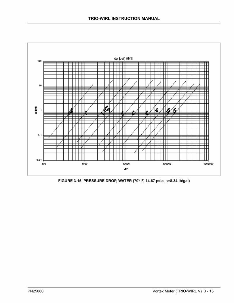
TRIO-WIRL INSTRUCTION MANUAL
FIGURE 3-15 PRESSURE DROP, WATER (70o F, 14.67 psia, ρ=8.34 lb/gal)
PN25080 Vortex Meter (TRIO-WIRL V) 3 - 15

TRIO-WIRL INSTRUCTION MANUAL
3.6 Specifications3.6.1 Model Overview
MODEL
AccuracyLiquids ≤ ± 0.75 % of rate
Gases and Steam ≤ ± 1 % of rate
Reproducibility ≤ ± 0.2 % of rate
Allowable viscosity for liquids ≤ 7.5 cps
Typical flow range 1:20
Typical up-/downstream straight lengths 15 x D / 5 x D
Flowmeter Primary
Process Connections Flanges (DIN, ANSI. JIS) 1/2”-12”/DN15-DN300
Wafer Style (DIN, ANSI. JIS) 1/2”-8”/DN15-DN200
Sensor Design Single sensor YES, optional with integrated temperature measurement
Fluid TemperatureStandard -67 °F to 536 °F
High Temperature (available soon) -67 °F to 750 °F
Protection Class NEMA 4X (IP67)
Materials
Sensor 316 SS or Hast C
Shedder Body 316L SS or Hast C
Meter Housing 316L SS or Hast C
Sensor Gasket Graphite, Kalrez, Viton, PTFE
Approvals / Certifications
Intrinsically Safe &Explosion-Proof Design FM / CSA Approved
Explosion-Proof Class I; Div.1; Groups B-DIntrinsically Safe Class I; Div. 1; Groups A-D
Non-Incendive for Class I; Div. 2; Groups A-DDust Ignition-proof Class II; Div. 1; Groups E-G
VT4000 VR4000
Vortex Meter (TRIO-WIRL V) 3 - 16 PN25080
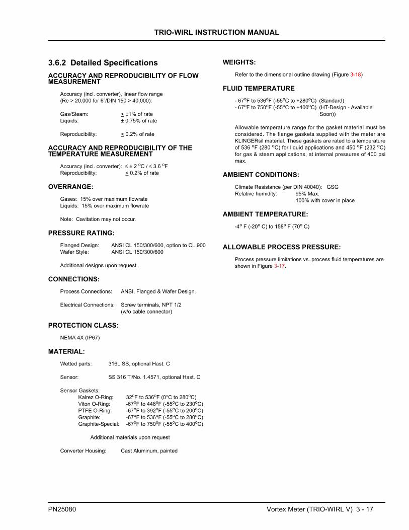
TRIO-WIRL INSTRUCTION MANUAL
3.6.2 Detailed SpecificationsACCURACY AND REPRODUCIBILITY OF FLOW MEASUREMENT
Accuracy (incl. converter), linear flow range(Re > 20,000 for 6”/DIN 150 > 40,000):
Gas/Steam: < ±1% of rateLiquids: ± 0.75% of rate
Reproducibility: < 0.2% of rate
ACCURACY AND REPRODUCIBILITY OF THE TEMPERATURE MEASUREMENT
Accuracy (incl. converter): ≤ ± 2 oC / ≤ 3.6 oFReproducibility: < 0.2% of rate
OVERRANGE:Gases: 15% over maximum flowrateLiquids: 15% over maximum flowrate
Note: Cavitation may not occur.
PRESSURE RATING:Flanged Design: ANSI CL 150/300/600, option to CL 900Wafer Style: ANSI CL 150/300/600
Additional designs upon request.
CONNECTIONS:Process Connections: ANSI, Flanged & Wafer Design.
Electrical Connections: Screw terminals, NPT 1/2(w/o cable connector)
PROTECTION CLASS:NEMA 4X (IP67)
MATERIAL:Wetted parts: 316L SS, optional Hast. C
Sensor: SS 316 Ti/No. 1.4571, optional Hast. C
Sensor Gaskets:Kalrez O-Ring: 32oF to 536oF (0°C to 280oC)Viton O-Ring: -67oF to 446oF (-55oC to 230oC)PTFE O-Ring: -67oF to 392oF (-55oC to 200oC)Graphite: -67oF to 536oF (-55oC to 280oC)Graphite-Special: -67oF to 750oF (-55oC to 400oC)
Additional materials upon request
Converter Housing: Cast Aluminum, painted
WEIGHTS:Refer to the dimensional outline drawing (Figure 3-18)
FLUID TEMPERATURE- 67oF to 536oF (-55oC to +280oC) (Standard)- 67oF to 750oF (-55oC to +400oC) (HT-Design - Available
Soon))
Allowable temperature range for the gasket material must beconsidered. The flange gaskets supplied with the meter areKLINGERsil material. These gaskets are rated to a temperatureof 536 oF (280 oC) for liquid applications and 450 oF (232 oC)for gas & steam applications, at internal pressures of 400 psimax.
AMBIENT CONDITIONS:Climate Resistance (per DIN 40040): GSGRelative humidity: 95% Max.
100% with cover in place
AMBIENT TEMPERATURE:-4o F (-20o C) to 158o F (70o C)
ALLOWABLE PROCESS PRESSURE:Process pressure limitations vs. process fluid temperatures are shown in Figure 3-17.
PN25080 Vortex Meter (TRIO-WIRL V) 3 - 17

TRIO-WIRL INSTRUCTION MANUAL
FIGURE 3-16 AMBIENT / FLUID TEMPERATURE RELATIONSHIP
Fluid Temperature [°C]
Ambi
ent T
empe
ratu
re [o C
]
1)
AllowableTemperature Range HT-Design
≤ 400°Cfor Std. Design(≤ 280°C) Side View, Pipeline
Installation forFluid Temperatures > 150°C
-20
FIGURE 3-17 PROCESS PRESSURE vs. PROCESS FLUID TEMPERATURE
Fluid Temperature [°C]
Proc
ess
Pres
sure
[bar
]
Only High Temperature DesignTRIO-WIRL VT/VR
oF = [ oC x 1.8 ] + 32
1 Bar = 14.50 psi
1) Cables for the supply power,terminals 31 & 32, and the contactoutput, terminals 41 & 42, whichare suitable for temperatures toT= 230oF (110°C), can be usedwithout any temperature reduc-tions. Cables which are only suit-able for temperatures to T= 176oF(80°C), reduce the temperatureranges as shown in Figure 3-16.
oF = [ oC x 1.8 ] + 32
Vortex Meter (TRIO-WIRL V) 3 - 18 PN25080

PN25080
Vortex M
eter (TRIO
-WIR
L V) 3 - 19
TRIO
-WIR
L INSTR
UC
TION
MA
NU
AL
REF. OD-10-2828_r0
FIGU
RE 3-18 O
UTLIN
E DIM
ENSIO
NS, VT/VR
PRIM
ARY

TRIO-WIRL INSTRUCTION MANUAL
CHAPTER 4 Converter
4.1 GeneralThe TRIO-WIRL flow metering system is designed as a2-wire instrument, i.e. the supply power and the currentoutput signal (4-20 mA) both use the same pair of con-nection leads.
Two converter mounting versions are available, integral( models ST/VT) and remote (models SR/VR).
INTEGRAL
The TRIO-WIRL VT/ST models are supplied with anintegrally mounted microprocessor-based signal con-verter as shown in Figure 4-1. The converter usesstate-of-the-art Digital Signal Processor (DSP) technol-ogy for superior flow and vibration noise immunity. Thiscombination of flowmeter and electronics allows maxi-mum flexibility for on-site calibration and maintenance.Database interrogations and changes at the flowmetermay be performed using the three pushbuttons or byactivating three magnetic switches using a magnetic"stick". The two line, 16 character LCD display permitscontinuous monitoring of the flow rate and totalizerusing multiplexing, if desired.
REMOTE
The TRIO-WIRL VR/SR models (Figure 4-2) are basedon the VT/ST converter technology and include all theoptions available in the VT/ST models. The differenceis that the converter is mounted remotely from the flow-meter primary when the primary is installed in a loca-tion difficult to access. The converter may be either
wall-mounted or pipe-mounted (pipe-mounting hard-ware is shown in Figure 4-3).The remote design alsooffers advantages when the ambient conditions at theflowmeter primary are extreme. The maximum distancebetween the converter and the flowmeter primary is 10meters. A special cable is supplied with the meter tointerconnect the flowmeter primary and the converterand is permanently attached to the converter.
FIGURE 4-1 INTEGRAL TRIO-WIRL MODEL VT
.
FIGURE 4-2 REMOTE TRIO-WIRL MODEL VR
FIGURE 4-3 VR/SR PIPE-MOUNT BRACKET
PN25080 Converter 4 - 1

TRIO-WIRL INSTRUCTION MANUAL
After the installation has been completed, the cablecan be cut to the length required to reach he flowmeterprimary. Because the signals between the flowmeterprimary and converter are not amplified all connections
must be made with care and the leads positioned in theconnection box so that they are not affected by vibra-tions.
4.2 Converter PositioningDuring installation, the converter housing may berotated and positioned for optimal readability. A simplemechanical block prevents the housing from beingrotated more than 330°. This protects the cable whichis connected to the flowmeter primary.
The procedure to rotate the converter is as follows(refer to Figure 4-4):
1. Loosen the locking screw on the converter housingwith a 4 mm hex wrench.
2. Press out the locking bolt.
3. Rotate the converter housing to the desired position.
4. Reinsert the locking bolt.
5. Tighten the locking screw..
Additional versatility is provided by the ability to rotatethe display 90o for applications which require the meterto be mounted in a vertical pipeline. The procedure torotate the display is as follows:
1. Unscrew and remove the display housing cover.
2. Remove the display bezel by un-clipping the twotabs on the sides of the bezel. Pull the tabs slightly out-ward and upward to remove the bezel and provideaccess to the PCB mounting screws.
3. Remove the 4 mounting screws that secure the dis-play PCB assembly to the converter PCB stack.
4. Rotate the display either 90o clockwise or counter-clockwise, depending on the desired orientation.
5. Resecure the display PCB by re-installing the 4mounting screws.
6. Re-attach both the display bezel and the displayhousing cover.
4.3 Data EntryFigure 4-5 shows the converter’s display and program-ming pushbutton locations.The data may be enteredusing either the 3 pushbuttons (DATA, STEP & C/CE)
on the converter or by activating the magnetic sensorswith the Magnetic Stick when the housing cover isclosed
FIGURE 4-4 CONVERTER HOUSING ROTATION
Press
-
outbolts
Loosen lockingscrew
Converter 4 - 2 PN25080

TRIO-WIRL INSTRUCTION MANUAL
.
4.3.1 ENTER Function for Magnetic Stick OperationThe ENTER function is initiated when the DATA/ENTER magnetic sensor is activated for more than 3seconds. The display blinks to indicate that the functionis active.
The converter remains on-line during data entry, i.e.,the current output continues to indicate the actualinstantaneous flowrate values and the pulse outputcontinues to totalize. The individual button functionsare described in the following table:
Display may be rotated either 90°
CW or CCW
Buttons forDirect Entry
Magnetic
DATASTEP
C/CE
Sensors
FIGURE 4-5 CONVERTER KEYPAD & DISPLAY
C/CE The C/CE-key is used to toggle back and forth between the operating mode and the menu display. It is also used for the "exit" function to exit from the menus.
STEP ↑ The STEP-key is one of two arrow keys. STEP is used to scroll forward through the menu. All desired parameters can be accessed.
DATA ↓ The DATA-key is one of two arrow keys. DATA is used to scroll backward through the menu. All desired parameters can be accessed.
ENTER The ENTER function requires that both arrow keys, STEP and DATA, be pressed simultaneously. ENTER is utilized to access the values in the parameter to be changed and to accept the new values or selections. The ENTER function is only active for approx. 10 Sec. If no entries are made dur-ing this 10 Sec. time interval the old value is redisplayed on the converter. If an additional 10 seconds elapses without any action, the standard process display reappears.
STEP
DATA
PN25080 Converter 4 - 3

TRIO-WIRL INSTRUCTION MANUAL
4.3.2 Data Entry OverviewAction Use Keys= Display Information
Note: The program protection must be turned off before data can be entered(refer to Section 5.5.2)
Turn off Locked mode - Qv % Standard-Display10.5
↓ ↓ ↓
1) Advance to Progr. Level STEP or DATA Progr. Level
↓ ↓ ↓
2) Enter Menu ENTER Locked
↓ ↓ ↓ENTER Locked_ An "underscore"
indicates "selectable"↓ ↓ ↓
3) Select desired Mode STEP or DATA Standard_
↓
4) Enter Code (if not "0") ENTER Program Protection Code
Direct Numeric EntryExample: Set Qmax value
Entry from a TableExample: Set meter size
Action Keys = Display Information Action Keys = Display Information
1) Find Parameter“Qmax” STEP or DATA Qmax 1)Select parameter
"Meter size“ STEP or DATA Metersize
↓2)Check “Qmax”
setting ENTER 5.000 2) Check "Meter Size“ ENTER 15 mm
l/s 1/2 in↓
3) Change Parameter“Qmax” ENTER 0 3) Change parameter
"Meter Size“ ENTER 15 mml/s 1/2 in
↓4) Enter the desired 4 . 5 2 5 4) Select "Meter
Size“ from table. STEP or DATA 50 mmnumber series l/s 2 in
4xDATA 5)Accept newMeter Size ENTER Meter
STEP Size10xDATA (decimal point)STEP5xDATASTEP2xDATASTEP5xDATA
4) *The C/CE key clears the entry↓
5)Accept new Qmaxvalue ENTER 4.525
l/s
Exit from Qmax or Meter SizeFind Program Level STEP or DATA *Prog. Level*
↓ ↓ ↓Access parametersetting ENTER Menu mode
↓ ↓ ↓Turn program protectionon again (Step or Data) ENTER Menu mode
Locked_↓ ↓ ↓
Select Program Level STEP or DATA Program level
↓ ↓ ↓ENTER
↓ ↓ ↓Return to Standard Display/Process Information C/CE Qv % Standard Display10.5
!
Converter 4 - 4 PN25080

TRIO-WIRL INSTRUCTION MANUAL
4.4 Operation and ConfigurationAfter the power is applied to the instrument, it automat-ically executes several self test routines. After theyhave successfully completed, the process informationis displayed on the LCD display. The operator may con-figure which units are to be displayed:
Actual flowrate in direct reading engineering units:
Totalized actual flow:
Fluid temperature:
A Multiplex-Mode is also selectable for the display. Inthis mode it is possible to display several parameters.The parameter shown on the display alternates every10 seconds.
4.5 Digital Communications ProtocolsTRIO-WIRL is available (or will be available) with thefollowing communications protocols:
* HART
* Profibus
* Fieldbus Foundation
* SmartVision
4.5.1 HART ProtocolThe HART-Protocol provides for digital communicationbetween a process control system/PC, handheld termi-nal and the TRIO-WIRL. All parameters, such as meterlocation specific data, can be transmitted from the con-verter to the process control system or PC. In thereverse direction it is possible to reconfigure the con-verter.
The digital communication utilizes an ac signal super-imposed on the current output (4-20 mA) which doesnot affect any other instruments connected to the out-put.
The Microsoft WINDOWS-based software programSMART VISION may be used to operate and config-ure the converter using HART-Communication.SMART VISION is a universal communication softwaretool for intelligent field instruments, which uses a vari-
ety of communication methods to provide for dataexchange and includes a complete field instrument pal-ette. The main elements include parameter display,configuration, diagnosis, recording and data manage-ment for all intelligent field instruments which satisfythe communication requirements.
4.5.1.1 Communication
1. Over FSK-Modem with Point-to-Point or Multidropoperation.
2. Over ABB Automation Products HART-Multiplexer.
SMART VISION is compatible with standard modernPC’s or notebook computers running MS Windows Ver-sion 3.1 and higher, Windows 95/98 and Windows NT.
4.5.1.2 Transmission Mode
FSK-Modulation on the 4-20 mA current output per Bell202 Standard. Maximum signal amplitude 1.2 mAPP.
Load, Current Output
Minimum = 250 Ω, maximum = 750 ΩMaximum cable length = 1500 m AWG 24 twisted andshielded
Q f ft 3 / m1 3 . 5 6
Qf ft 3 4 0 9 . 8
T ° F366.1
PN25080 Converter 4 - 5

TRIO-WIRL INSTRUCTION MANUAL
4.5.1.3 Baudrate
1200 Baud
Logic 1: 1200 HzLogic 0: 2200 Hz
Current Output During an Alarm Condition = 22.4 mA
FIGURE 4-6 HART-Communication
(Available Soon)
(Available Soon)
Converter 4 - 6 PN25080

TRIO-WIRL INSTRUCTION MANUAL
4.6 Specifications4.6.1 Overview
CONVERTER
Supply PowerFor analog output 4-20 mA 14-46 V (EEx < 28 V)
For Profibus PA (in prep.) < 10 mA
Self Monitor yes
Display 2 x 8 character Local display/totalization and Magnet Stick operation
Contact Output(Optocoupler for standardand Ex “d” or Current-lim-ited contact for Ex “ib”)
Can be configured as alarm limit contact (flowrate or temperature),system alarm output or pulse output (Refer to Figure 5-13)
CommunicationHART-Protocol
Profibus PA & Fieldbus Foundation available soon
TRIO-WIRLVR or SR
2” pipe mount for con-verter.
- yes, optional - Yes, optional
Signal cable length between primary and con-verter
- 30 ft. (10 m) max. - 30 ft. (10 m) max.
APPROVALS / CERTIFICATIONSIntrinsically
Safe &Explosionproof
Design
FM / CSAExplosion-Proof Class I; Div.1; Groups B-DIntrinsically Safe Class I; Div. 1; Groups A-D
Non-Incendive for Class I; Div. 2; Groups A-DDust Ignition-proof Class II; Div. 1; Groups E-G
TRIO-WIRL VT TRIO-WIRL VR TRIO-WIRL ST TRIO-WIRL SR
PN25080 Converter 4 - 7

TRIO-WIRL INSTRUCTION MANUAL
4.6.2 Detailed SpecificationsKEYPAD & DISPLAY
FLOW RANGES:The flow range end value can be continuously set between0.15 x Qvmax and Qvmax.
PARAMETER SETTING:Data is entered using the 3 pushbuttons or using the magneticstick when the housing is closed.
The data is entered in a clear text dialog with the display orthough digital communication utilizing HART-Protocol, ProfibusPA or Fieldbus Foundation (in preparation).
DATA PROTECTION:The totalizer values and the meter location specific parametersare stored for a period of up to 10 years in an EEPROM whenthe power is turned off or during a power interruption.
FUNCTION TESTS:The individual internal subassemblies of the converter can bechecked using the built in function tests in the software. Simu-lated current output values can be entered during start-up (man-ual process control). The contact output can also be manuallyactuated for testing purposes.
DAMPING:Can be set between 0.5 and 100 sec., equivalent to 5T @QVMIN
QVMIN (LOW FLOW CUTOFF):Can be set between 0 and 10% of Qvmax (maximum actual vol-ume flowrate for the flowmeter size).
SUPPLY POWER:Standard: 14 to 46 V DCEx-Design: 14 to 28 V DCRipple: max. 5 % or ± 1.5 Vpp
POWER:< 1 W
PROTECTION CLASS:NEMA 4x / IP 67
OUTPUT SIGNALS:Current output for flowrate signal (volume or mass):4-20 mA, load ≤ 750 Ω
CONTACT OUTPUT:The following functions for the contact output can be selected inthe software:
-Limit alarm, flowrate: Min, Max or Min-Max-Limit alarm, temperature:Min, Max or Min-Max-System alarm-Pulse output * : fmax: 100 Hz;
Pulse width: 1 - 256 ms
* The pulse output is intended to interface with a Totalizer. Theinterval between any two pulses may not represent the instanta-neous flow rate.
CONTACT CONFIGURATION:Standard and Ex “d”: Optocoupler UH = 16-30 V,
IL = 2-15 mA
-Ex “ib”: Current-limited-Contact(Refer to Figure 5-14)
DISPLAY:High contrast LC-Display, 2 x 8 characters. For display of theinstantaneous flowrate, totalized flow or fluid temperature val-ues (option).
Using the multiplex function it is possible to alternately displaytwo values (e.g. flowrate and totalizer values) alternately.
+/- 90° Rota-
3 Buttons for direct operation
Magnet Stick-operation
Magnet Stick-operation
FIGURE 4-7 Converter Keypad and Display
Converter 4 - 8 PN25080

TRIO-WIRL INSTRUCTION MANUAL
FIGURE 4-8 OUTLINE DIMENSIONS, VR/SR IN WALL-MOUNT HOUSING
1.22
2.13 (1.46)* 4.922.24
3.94
2.76
( )* = w/o Display
All Dimensions Shown in Inches
0.25
0.85
PN25080 Converter 4 - 9
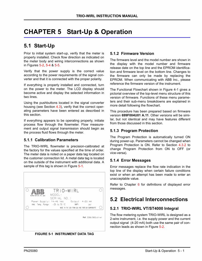
TRIO-WIRL INSTRUCTION MANUAL
CHAPTER 5 Start-Up & Operation
5.1 Start-UpPrior to initial system start-up, verify that the meter isproperly installed. Check flow direction as indicated onthe meter body and wiring interconnections as shownin Figures 5-2, 5-4 & 5-5.
Verify that the power supply is the correct valueaccording to the power requirements of the signal con-verter and that it is connected with the proper polarity.
If everything is properly installed and connected, turnon the power to the meter. The LCD display shouldbecome active and display the selected information intwo lines.
Using the pushbuttons located in the signal converterhousing (see Section 4.3), verify that the correct oper-ating parameters have been entered as described inthis section.
If everything appears to be operating properly, initiateprocess flow through the flowmeter. Flow measure-ment and output signal transmission should begin asthe process fluid flows through the meter.
5.1.1 Calibration ParametersThe TRIO-WIRL flowmeter is precision-calibrated atthe factory for the values specified at the time of order.The meter data is noted on a paper data tag located onthe customer connection lid. A metal data tag is locatedon the outside of the instrument with additional data. Asample of this tag is shown in Figure 5-1.
5.1.2 Firmware VersionThe firmware level and the model number are shown inthe display with the model number and firmwarerelease date on the top line and the EPROM identifica-tion and firmware level on the bottom line. Changes tothe firmware can only be made by replacing theEPROM. When communicating with ABB Inc., pleasereference the firmware version of the instrument.
The Functional Flowchart shown in Figure 4-1 gives apictorial overview of the top-level menu structure of thisversion of firmware. Functions of these menu parame-ters and their sub-menu breakdowns are explained inmore detail following the flowchart.
This procedure has been prepared based on firmwareversion 699F004U01 A.11. Other versions will be simi-lar, but not identical and may have features differentfrom those discussed in this section.
5.1.3 Program ProtectionThe Program Protection is automatically turned ONduring power-up. Parameters cannot be changed whenProgram Protection is ON. Refer to Section 4.3.2 tochange Program Protection from ON to OFF (orvice-versa).
5.1.4 Error MessagesError messages replace the flow rate indication in thetop line of the display when certain failure conditionsexist or when an attempt has been made to enter anunacceptable value.
Refer to Chapter 6 for definitions of displayed errormessages.
5.2 Electrical Interconnections5.2.1 TRIO-WIRL VT/ST4000 IntegralThe flow metering system TRIO-WIRL is designed as a2-wire instrument, i.e. the supply power and the currentoutput signal (4-20 mA) both use the same pair of con-nection leads as shown in Figure 5-2.
FIGURE 5-1 INSTRUMENT DATA TAG
Ref. -r.
PN25080 Start-Up & Operation 5 - 1
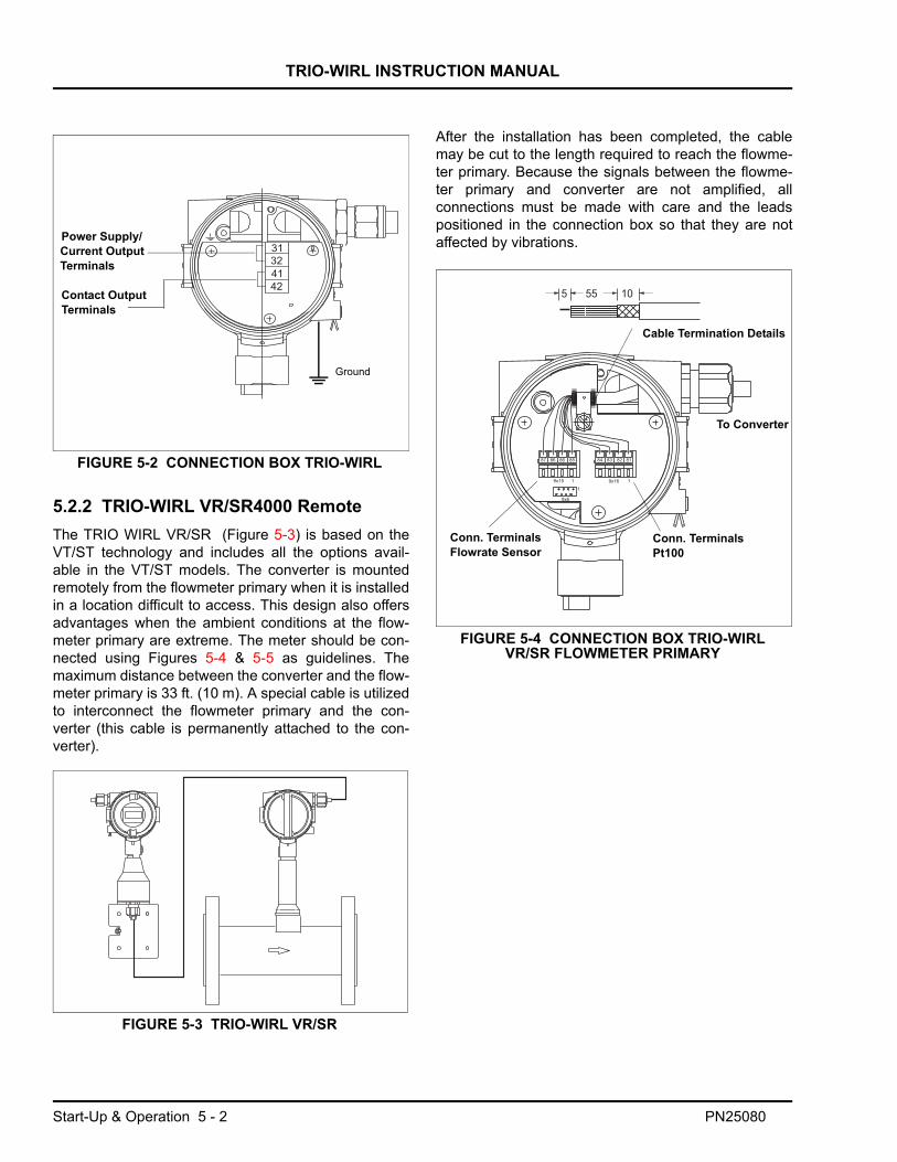
TRIO-WIRL INSTRUCTION MANUAL
5.2.2 TRIO-WIRL VR/SR4000 RemoteThe TRIO WIRL VR/SR (Figure 5-3) is based on theVT/ST technology and includes all the options avail-able in the VT/ST models. The converter is mountedremotely from the flowmeter primary when it is installedin a location difficult to access. This design also offersadvantages when the ambient conditions at the flow-meter primary are extreme. The meter should be con-nected using Figures 5-4 & 5-5 as guidelines. Themaximum distance between the converter and the flow-meter primary is 33 ft. (10 m). A special cable is utilizedto interconnect the flowmeter primary and the con-verter (this cable is permanently attached to the con-verter).
.
After the installation has been completed, the cablemay be cut to the length required to reach the flowme-ter primary. Because the signals between the flowme-ter primary and converter are not amplified, allconnections must be made with care and the leadspositioned in the connection box so that they are notaffected by vibrations.Power Supply/
Current OutputTerminals
Contact OutputTerminals
Ground
FIGURE 5-2 CONNECTION BOX TRIO-WIRL
FIGURE 5-3 TRIO-WIRL VR/SR
Conn. TerminalsPt100
Cable Termination Details
To Converter
Conn. TerminalsFlowrate Sensor
FIGURE 5-4 CONNECTION BOX TRIO-WIRLVR/SR FLOWMETER PRIMARY
Start-Up & Operation 5 - 2 PN25080
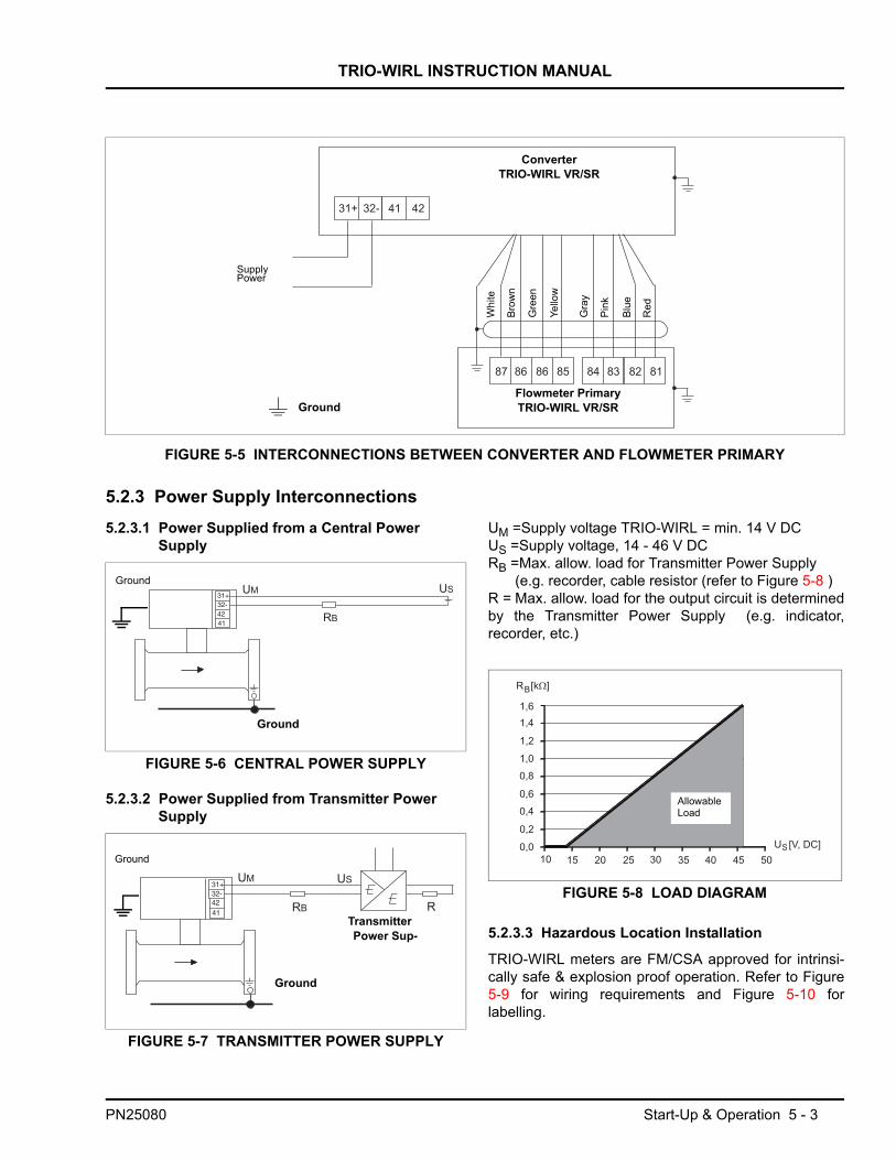
TRIO-WIRL INSTRUCTION MANUAL
5.2.3 Power Supply Interconnections5.2.3.1 Power Supplied from a Central Power
Supply
5.2.3.2 Power Supplied from Transmitter Power Supply
UM =Supply voltage TRIO-WIRL = min. 14 V DCUS =Supply voltage, 14 - 46 V DCRB =Max. allow. load for Transmitter Power Supply
(e.g. recorder, cable resistor (refer to Figure 5-8 )R = Max. allow. load for the output circuit is determinedby the Transmitter Power Supply (e.g. indicator,recorder, etc.)
5.2.3.3 Hazardous Location Installation
TRIO-WIRL meters are FM/CSA approved for intrinsi-cally safe & explosion proof operation. Refer to Figure5-9 for wiring requirements and Figure 5-10 forlabelling.
FIGURE 5-5 INTERCONNECTIONS BETWEEN CONVERTER AND FLOWMETER PRIMARY
ConverterTRIO-WIRL VR/SR
Flowmeter PrimaryTRIO-WIRL VR/SR
Supply Power
Ground
Red
Blue
Pink
Gra
y
Yello
w
Gre
en
Brow
n
Whi
te
FIGURE 5-6 CENTRAL POWER SUPPLY
FIGURE 5-7 TRANSMITTER POWER SUPPLY
Ground
Ground
Ground
Transmitter Power Sup-
Ground
AllowableLoad
FIGURE 5-8 LOAD DIAGRAM
PN25080 Start-Up & Operation 5 - 3
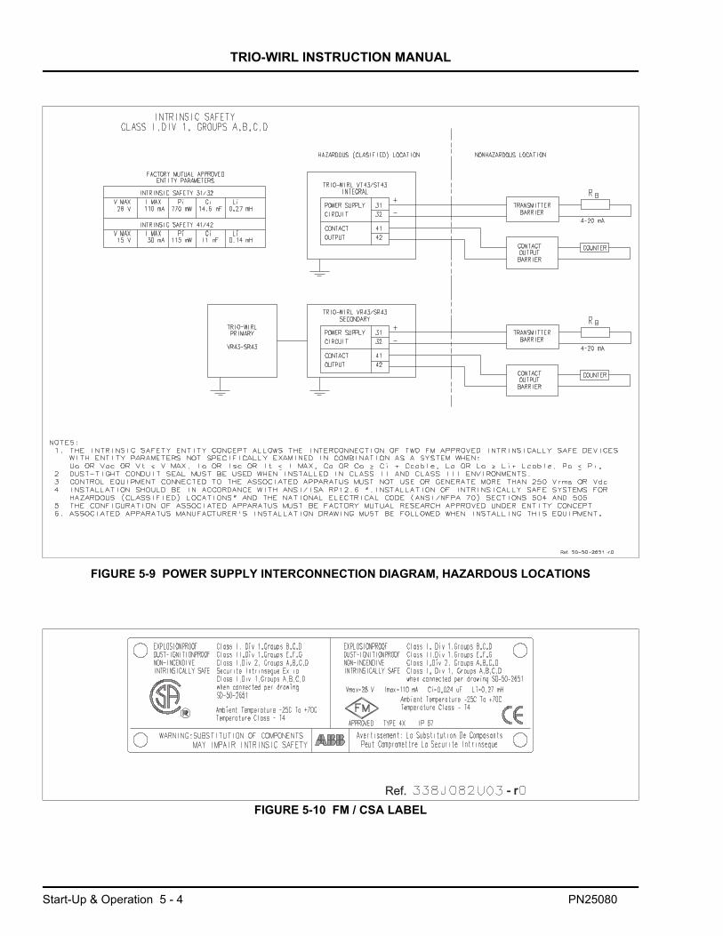
TRIO-WIRL INSTRUCTION MANUAL
FIGURE 5-9 POWER SUPPLY INTERCONNECTION DIAGRAM, HAZARDOUS LOCATIONS
Ref. -r.
FIGURE 5-10 FM / CSA LABELRef. - r- r
Start-Up & Operation 5 - 4 PN25080

TRIO-WIRL INSTRUCTION MANUAL
5.2.4 Contact Output Connections
The value of the resistance RE is a function of the sup-ply power UB and the selected signal current IB (referto Figure 5-12).
RE =
5.3 Converter Configuration5.3.1 Data-Entry CheckThe measurement system has been configured by thefactory prior to shipment based on the informationincluded with the customer order. All the required val-ues have been entered. Because the instruments canbe installed to measure liquids or gases, it is recom-mended that the following software parameter settingsbe checked at start-up:
4.Which flowrate units are to be used for the displayindications and for the totalizer values?
5.Enter the desired flow range in the units selectedabove in the parameter Qmax Operating Mode.
Entry range: 0.15 to 1.15 x Rangemax actual.
6.Check the low flow cutoff value in the parameter Qmin Actual
Entry range: 0 to 0.1 x Rangemax.
7.Select the units for the internal and external totalizersin the parameter Units Totalizer.
8.The response time of the converter can be set in theparameter Damping. Default setting is 3 sec.
9.Select submenu Display and select desired values,e.g.:
For main display select percentFor multiplex display select totalizer values
The measurement system is now ready for operation.
5.3.2 Additional Configuration Information5.3.2.1 Meter Size
This parameter is used to define the size of theinstalled flowmeter since the same converter can beused for all flowmeter sizes.
The meter size is set at the factory for the converter’sassigned flowmeter primary (see Instrument Tag).
Parameter Action
1. Meter size Select Meter Size. The displayed value must be identical to the size listed on the Instr. Tag
2. Operating mode
3. k-Factor Select k-Factor. The displayed value must be identical to the value listed on the Instr. Tag.
Con-tactOut-
TRIO-WIRL
Input, SPC etc.with UB = 16-30 V
41
42
FIGURE 5-11 CONTACT OUTPUT CONNECTION
UBIB-------
UB
in V
IB in mA
Remin = 2 kOhm
Re m
ax = 80 kOhm
FIGURE 5-12 RELATIONSHIP RE AT THE CONTACT OUTPUT AS A FUNCTION OF
Mass Units Volume UnitsParameter Action Parameter ActionOperating modeMass
select Operating modeVolume, Normal Standard, Actual
select from table
Density unitsQm
from table UnitsQv/Qn/Qs/ l/min
select from table
Operating density
enter Normal factor (only for Qs, Qn)
enter value
Units Qmkg/s
from table
PN25080 Start-Up & Operation 5 - 5

TRIO-WIRL INSTRUCTION MANUAL
5.3.2.2 Calibration K-Factor
The median (average) k-Factor value is displayed bynavigating to the above menu item and pressing Enter.
Each flowmeter is calibrated on a test stand at 5 flow-rate values. The 5 calibration factors are entered intothe converter and recorded on a calibration report andon a paper tag located in the customer connection lid.
Typical calibration factor values and the signal frequen-cies for liquids and gases are listed in the followingtable. These values are approximate guidelines only:
Vortex Flowmeter TRIO-WIRL V
Swirl Flowmeter TRIO-WIRL S
The converter calculates the actual flowrate using the follow-ing equations:
Q =
Where:
Q= Actual flowrate at operating conditions [m3/s]f = Frequency [1/s]k = Calibration k-Factor [1/m3]
5.3.2.3 Current Output
The measurement value output characteristic for thecurrent output is shown in Figure 5-13. Above the Qmin(operating mode) value the curve is a straight linewhose value at 4 mA is Q = 0 and whose value at 20mA is the value of Qmax (operating mode). The currentoutput for flowrates less than the low flow cutoff valueQmin is set 4 mA equivalent to Q = 0.
5.3.2.4 Hardware Configuration
The function assigned to the contact output (terminals41 & 42) is selected in this submenu. The menus Pulsewidth, Min and Max Q_Alarm or Min and MaxT_Alarm are displayed based on the selection of theoutput function. „
Meter Size
Inch DN
Typ.k-Factor
max [1/m3]
Liquidfmax atQvmax[Hz]
Gasfmax atQvmax[Hz]
1/2 15 30000 450 1840
1 25 80000 400 1825
1-1/2 40 21100 280 2000
2 50 10000 180 1250
3 80 2900 130 760
4 100 1300 80 650
6 150 380 55 425
8 200 166 43 310
10 250 66 28 235
12 300 39 23 190
Meter Size
Inch DN
Typ.k-Factor
max [1/m3]
Liquidfmax atQvmax[Hz]
Gasfmax atQvmax[Hz]
1/2 15 440000 185 1900
1 25 86000 135 1200
1-1/4 32 33000 107 1300
1-1/2 40 21000 110 1400
2 50 11100 90 1200
3 80 2900 78 690
4 100 1620 77 700
6 150 460 50 470
8 200 194 30 330
12 300 54 16 160
16 400 upon request 13 150
Median k-Factor
FIGURE 5-13 OUTPUT CURRENT CHARACTERISTICS
Selections Contact OutputFunction
Menus Displayed
I/HART None None
I/HART/Pulse_Bin Pulse output Pulse width
I/HART/Q_Alarm_ Flow alarm Min. and Max. Q_Alarm
I/HART/T_Alarm_ Temperature alarm Min. and Max. T_Alarm
I/HART/S_Alarm_ System alarm None
fk---
Start-Up & Operation 5 - 6 PN25080
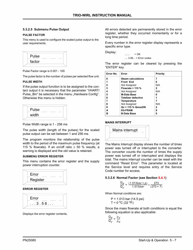
TRIO-WIRL INSTRUCTION MANUAL
5.3.2.5 Submenu Pulse OutputPULSE FACTORThis menu is used to configure the scaled pulse output to the user requirements.
Pulse Factor range is 0.001 - 100
The pulse factor is the number of pulses per selected flow unit.
PULSE WIDTHIf the pulse output function is to be assigned to the con-tact output it is necessary that the parameter “I/HART/Pulse_Bin“ be selected in the menu „Hardware Config“.Otherwise this menu is hidden.
Pulse Width range is 1 - 256 ms
The pulse width (length of the pulses) for the scaledpulse output can be set between 1 and 256 ms.
The program monitors the relationship of the pulsewidth to the period of the maximum pulse frequency (at115 % flowrate). If an on/off ratio ≥ 50 % results, awarning is displayed and the old value is retained.
SUBMENU ERROR REGISTERThis menu contains the error register and the supplypower interruption counter.
ERROR REGISTER
Displays the error register contents.
All errors detected are permanently stored in the errorregister, whether they occurred momentarily or for along time period.
Every number in the error register display represents aspecific error type.
Display:
The error register can be cleared by pressing the“ENTER“ key.
MAINS INTERRUPT
The Mains Interrupt display shows the number of timespower was turned off or interrupted to the converter.The converter counts the number of times the supplypower was turned off or interrupted and displays thetotal. The mains interrupt counter can be reset with thecommand “Reset Error”. This parameter is located atthe Service level and requires entry of the ServiceCode number for access.
5.3.2.6 Normal Factor (see Section 5.4.1)
When Normal conditions are:
P = 1.013 bar (14.5 psi)T = 0 oC (32 oF)
Since the mass flowrate at both conditions is equal thefollowing equation is also applicable:
Pulsefactor
Pulsewidth
ErrorRegister
Error. . . 3 . 5 6 . . .
Error No. Error Priority
0123456789AB
Steam calculationsFront EndNot AssignedFlowrate > 115 %Not AssignedM-Data BaseTotalizer defectiveTemperatureNot AssignedQv > 115 % QmaxDNKit-FRAMB-Data Base
70N/A2N/A017N/A290
Mains interrupt
QNQV-------- 1.013bar p+( )
1.013bar--------------------------------------- 273
273 T+( )-------------------------×=
QNQV--------
ρVρN------=
....... = OK
.... 3.56... = Error codes
PN25080 Start-Up & Operation 5 - 7

TRIO-WIRL INSTRUCTION MANUAL
Where:
QN = Normal flowrate at normal conditionsQV = Actual flowrate at operating conditionsp = Pressure at operating conditionsT = Temperature at operating conditions [°C]
= Density at operating conditions = Density at normal conditions
5.3.3 Configuring the Contact OutputThe contact output of the converter is configured at the factory based on the specified Model Number.
If desired, the contact output configuration may be changed. Disconnect power from the flowmeter and remove thecover. In order to change the switch positions, the converter electronics module must be removed from the hous-ing. Unscrew the 3 Phillips head mounting screws and remove the converter from the housing. Set the switch asshown in Figure 5-14. Carefully reinstall the converter in the housing, making certain that it is centered and tightenthe 3 mounting screws. Replace the converter cover.
ρVρN
Model Number Code Agency Approvals Contact Design
VT/VR43, ST/SR43 FM/CSA Optocoupler
41
42
41
42
1K
10K
Left PositionCurrent-limited-Contact
Right PositionOptocoupler
FIGURE 5-14 CONTACT OUTPUT CIRCUITS
Start-Up & Operation 5 - 8 PN25080

TRIO-WIRL INSTRUCTION MANUAL
5.4 TRIO-WIRL Menu StructureThe menu structure is subdivided into four user levels. Refer to Table 5-1 for menu items available in each level.
1ST LEVEL: STANDARDThe standard menu provides a quick means for config-uring the instrument. All user specific menu entriesrequired for operating the instrument can be set in thismenu.
2ND LEVEL: SPECIALISTIn contrast to the standard menu the complete set ofuser specific parameters are accessible in this menu.
3RD LEVEL: SERVICEThe Service-Menu is only accessible to ABB Inc. Cus-tomer Service personnel.
4TH LEVEL: LOCKED
Same menus displayed as in STANDARD mode.Allows displaying or verifying instrument parametersand settings but does not allow entering new data ormaking changes.
5.4.1 Configuring Gases, Steam or LiquidsThe following table lists selections for the available operating modes, required parameters and additional menus displayed.
OperatingMode1) Fluid Measurement
Method Equations Correction Parameters
Additional Menus Displayed
Liquid Qv Liquid Volume flowrate
LiquidQm (D)
Liquid Mass flowrate Constant operating density ρoper
Units DensityOperating densityUnits Qm
Liquid 2)
Qm(D,T)Liquid Mass flowrate Ref. density ρ0;
Ref. temp. T0 oC
Operating temp. Toper oC
Density Expansion Coefficient ß2
Units density Operating density Operating temperature Units Qm(Temperature is measured)
Liquid 2)
Qm (V, T)Liquid Mass flowrate Volume Expansion
Coefficient [%/K] ß1 3)
Ref. temp. T0 oC
Operating temp. Toper oC
Ref. density ρ0
Units Density Operating density Operating temperature Vol._Exp_coef Units Qm(Temperature is measured)
GasQv
Gas Volume flowrate at operating conditions
Gas Normal 2)
Qn (pT)Gas Normal flowrate
1.013 bar / 0°C0 - 1.013 bar / 20°C
Operating press. Poper absOperating temp. Toper
oCOperating pressureUnits Pressure(Temperature is measured)
Gas Std 2)
Qs (pT)Gas Standard flowrate
14. 7psia / 70°F14. 7psia / 60°F
Operating press. Poper absOperating temp. Toper
oFStandard density(Temperature is measured)
Gas StdQs (cmp)
Gas
Standard factor =
Standard factor as a constant(Compressibility Factor)
Standard factor
Gas Mass2)
Qm (pT)Gas Mass flowrate
Standard conditions14.7 psia @ 70 oF
Operating press. Poper absStandard density ρ0Operating temp. Toper
oF
Units DensityStandard densityStandard conditionsOperating temperaturePress_ Poper_abs Units Qm(Temperature is measured)
Gas MassQm (D)
Gas Mass flowrate Constant operating density ρoper
Units DensityOperating densityUnits Qm
Sat. Steam2)
QmSaturated steam
Mass flowrate
Corrections using Saturated Steam Tables
Operating temp. Toper Units Qm
Sat. SteamQv
Saturated steam
Volume flowrate at operating conditions
Qm Qv ρoper⋅=
Qm Qv ρ T( )⋅=
ρ T( ) ρ0 (1 Toper T0–( ) β2 )⋅+⋅=
Qm Qn ρ0⋅=
Qn Qv1 Toper T0–( ) β1⋅+( )
--------------------------------------------------------=
Qn QvPnoper
1 013bar,-------------------------
273K Tn+
273K Toper+----------------------------------⋅ ⋅=
Qs QvPsoper
14.7-----------------
460 Ts+
460 Toper+-----------------------------⋅ ⋅=
Qn Qv S dardtan( ) factor⋅=ρoper
ρ0-------------
Qm ρ0 Qs⋅=
Qs QvPs
14.7-----------
460 Ts+
460 Toper+--------------------------------⋅ ⋅=
Qm Qv ρoper⋅=
Qm Qv ρoper Toper( )⋅=
PN25080 Start-Up & Operation 5 - 9

TRIO-WIRL INSTRUCTION MANUAL
Qs = Standard flowrate [scfh]Qm = Mass flowrate [lb/h]Qv = Actual volume flowrate [acfhhQn = Normal flowrate [ncfh]Poper = Operating pressure (psia)Pn = Operating normal pressure (bars absolute)Ps = Operating standard pressure (psia)ß1 = Volume Expansion Coefficient 3)
ß2 = Density Expansion Coefficient 3)
ρ0 = Normal density (lbs/ft3)
ρoper = Operating density (lbs/ft3)To = Reference temp., oCToper = Operating temp., oCTs = Standard temp. (60 or 70 oF)Tn = Normal temp. (0 or 20 oC)1) The possible measurement methods are a function of the type of
flowmeter calibration.2) These measurement methods can only be selected when a tem-
perature measurement is integrated in the flowmeter.3) Units are in mils (0.1%)
5.5 Trio-Wirl Menu Display and Selections5.5.1 Changing The Displayed LanguageIf the display should activate in German-language mode rather than English upon start-up or applying power to theconverter, use the following procedure to change the displayed language to English. Maintain power to theTrio-Wirl electronics for a minimum of 60 seconds after making any changes to the configuration database, otherwise the changes will not be stored.
Action ⇒ Key = Display Information
First, turn Locked mode off - Standard Display
↓ ↓ ↓
1) Advance to programming level STEP or DATA
↓ ↓ ↓
2) Enter menu ENTER
↓ ↓ ↓
3) Make selectiondisplay „Programming Level” ENTER Mode is selectable when
"underscore" is displayed
↓ ↓ ↓
4) Advance to " Standard" Program-ming Level STEP or DATA
↓ ↓ ↓
4) Select " Standard" ProgrammingLevel ENTER
↓ ↓ ↓
5) Menu itemFind "Language” STEP or DATA
↓ ↓ ↓
6) Make selectiondisplay "Language” ENTER
↓ ↓ ↓
7) Menu itemFind "English” STEP or DATA
↓ ↓ ↓
8) Select "English" ENTER Menus are now displayed in English
Qv %10.5
Progr.Ebene
Gesperrt
Gesperrt_
Standard__
Progr._Ebene
Sprache
Deutsch_
Englisch_
Language
Start-Up & Operation 5 - 10 PN25080

TRIO-WIRL INSTRUCTION MANUAL
5.5.2 Turning Locked Mode On/ OffAfter power-up, the converter operates in the Locked mode and data may not be entered. In order to enter orchange data, the mode must be changed to either the Standard, Specialist or Service mode. The mode-changeis made in the Program Level menu. After the mode is changed, a program protection code must be enteredusing the Data & Step buttons, unless the code has been set to "0".
If the Service mode is selected, a service code is required to enable entry into the Service Mode. The mode hier-archy is Standard Specialist Service and the number of changeable parameters shown in the menusincreases with each mode level.
Entry into Service mode is required to gain access to the following parameters:
* PT100 Sensor enable
* Fluid selections
* K-factor
* Flow & temperature calibration data entry
* Service data entry
Action ⇒ Key = Display Information
Turn Locked mode OFF - Standard Display
↓ ↓ ↓
1) Advance to Progr. Level STEP or DATA
↓ ↓ ↓
2) Enter Menu ENTER
↓ ↓ ↓
3) Display Programming Level ENTER Mode is selectable when "underscore" is displayed
↓ ↓ ↓
4) Select desired Programming Level for processing STEP or DATA
↓ ↓
5) Return to Menu Level ENTER Locked mode is now OFF
Qv %10.5
Progr.Level
Locked
Locked_
Standard_
Specialist_
Service_
Progr.Level
Note:Before a parameter can be changed or entered the Locked-mode must be turned off (Also refer to Section 5.5.2).
!
PN25080 Start-Up & Operation 5 - 11

TRIO-WIRL INSTRUCTION MANUAL
After completing the programming/configuration of the converter, the Program Protection should be turned on again
Action ⇒ Key = Display Information
Turn Locked mode ON - Standard Display
↓ ↓ ↓
1) Advance to Progr. Level STEP or DATA
↓ ↓ ↓
2) Enter Menu ENTER Display shows present pro-gramming level
↓ ↓ ↓
3) Display Programming Levels ENTER Mode is selectable when "underscore" is displayed
↓ ↓ ↓
4) Select Locked programming level STEP or DATA
↓ ↓
5) Return to Menu Level ENTER Locked mode is now ON
Qv %10.5
Progr.Level
Standard
Standard_
Locked_
Progr.Level
Note:Locked-mode must be turned off before data can be entered or changed.
!
Start-Up & Operation 5 - 12 PN25080

TRIO-WIRL INSTRUCTION MANUAL
5.5.3 Top-Level Menu StructureThe table to the right lists all of the top-level menus contained in the TRIO-WIRL firmware vs. the four menu pro-gramming modes:
TABLE 5-1. TOP-LEVEL MENU STRUCTURE
Menu Item Menu Programming Levels/ModesLocked Standard Specialist Service
Program LevelProg. Protection CodeLanguagePrimaryMeter SizeMedian K-FactorSchedule CorrectionFlow ModeUnit DensityReference DensityNormal DensityCompressibilityStandard ConditionsUnit TemperatureReference TemperatureUnit PressurePressure Poper ABSVolume ExtensionUnit QvolUnit QmQmaxDN OperQmaxQmin OperatingTotalizerDampingHardware Config.Iout at AlarmPulse FactorPulse WidthDisplayError RegisterSelf CheckInstr. AddressInstrument No.Order No.PT100 SensorLinearizationD-Base HandlingInit FlashFlash ChecksumAdjust I=4mAAdjust I=20mAMin. CurrentDSP ParVib ParTemp ParService DisplayTRIO-WIRL Firmware ID
Indicates the availablemenus for the given pro-gramming mode.
Indicates Menu Itemsthat appear dependingon other menu selec-tions.
PN25080 Start-Up & Operation 5 - 13

TRIO-WIRL INSTRUCTION MANUAL
5.5.4 Complete Menu Structure Overview and Data EntryMenus shown shaded are included in the Standard Level.
Key Submenu/ParameterSubmenu/ Parameter
Setting
Submenu/SelectParameter
Selections EntryType Comments
Enter Standard from table Standard: This menu includes all the user specific menu parameters for operat-ing the instrument;
Specialist: This menu includes the complete set of user specific menu parame-ters;
Service: This menu includes additional parameters which can be accessed after enter-ing the correct Service Code No. (only for ABB Service)
Specialist
ENTER
2xENTER
If a number differing from "0“ (Factory setting) has been selected for the Program Protection Code, then this code (1-9999) must be entered to turn the protection off.
Enter English/German from table Language for the display text
Enter Display of the Flowmeter primary selection SWIRL = TRIO-WIRL SVORTEX = TRIO-WIRL V
EnterDisplay of the flowmeter primary size
A=ANSI D=DIN
Enter Display of the calibration fac-tor value; k-Factor
Enter Sched.40Sched. 80
Parameter is only displayed for a flowmeter primary with ANSI process connections: Correction for the inside diameter differences between Sched. 40 and 80
Progr.Level
LockedENTER
Standard_
Specialist
Service_ EnterSRV-Code_
Pg.ProtCode
OldCode ENTER
0
NewCode ENTER
9999
Language EnglishENTER
English_
German_
Primary VORTEXVT / VR_
Metersize
A 80 mm3in
Mediank-factor
52000.01/m3
ScheduleCorrect
Sched.80
Start-Up & Operation 5 - 14 PN25080

TRIO-WIRL INSTRUCTION MANUAL
Key Submenu/ParameterSubmenu/ ParameterSetting
Submenu/SelectParameter
Selections EntryType Comments
Enter from tableFlow Mode:Fluid = Liquid(Refer to Section 5.4.1)
Notes:
1. The Operating Mode selections dis-played are a function of the fluid and the sensor design. (See Ordering Informa-tion)
2. The fluid selection is in the Service mode’s K-Linearity submenu. The PT100 sensor enabling selection is in the Service mode’s 100PT submenu
3. The entry of a service code is required to enter the Service mode.
Fluid = LiquidFlow Mode: Mass(Refer to Section 5.4.1)
Fluid = LiquidFlow Mode: Mass (Refer to Section 5.4.1)
Fluid = LiquidFlow Mode: Mass(Refer to Section 5.4.1)
Fluid = Gas (Refer to Section 5.4.1)Flow mode: Actual flow
Normal flowrate = Gas(Refer to Section 5.4.1)
Standard flowrate: Gas(Refer to Section 5.4.1)
Normal flowrate: Gas(Refer to Section 5.4.1)
Mass flowrate: Gas(Refer to Section 5.4.1)
Mass flowrate: Gas(Refer to Section 5.4.1)
Mass flowrate: Sat. steam(Refer to Section 5.4.1)
Actual flowrate: Sat. steam
Enter
g/l, g/cm3, g/l, kg/l, kg/l, kg/m3, lb/ft3, lb/ugl, g/ml_,
from table
Menu displayed for selection:Liquid Qm (D,T), Liquid Qm (V,T), Gas Mass Qm (pT), Gas Mass Qm(D)
Enter 0.001 - 0,100 from table Menu displayed for selection:Liquid Qm (D,T), Liquid Qm (V,T), Gas Mass Qm(D)
Enter 0.001 - 0.100 from table Menu displayed for selection:Gas Mass Qm (pT)
Enter 0.001 - 1000.000 numericMenu displayed for selection:Gas Stnd. Qs(CMP)Factor of compressibility = ρb : ρ0
Flowmode
LiquidQV ENTER
LiquidQv_ _
LiquidQm(D)
LiquidQm(D,T)
LiquidQm(V,T)
Gas Qv_
Gas NormQn(pT)_
Gas StndQs(pT)
Gas StndQs(CMP)
Gas MassQm(pT)
Gas MassQm(D)
Steamsatu Qm
Steamsatu Qv
UnitDensity
kg/l_ENTER
lb/ft3_
Referenc density
1.000kg/l_ _ ENTER
0kg/l_
Standard Density
0.001 kg/lkg/l_ ENTER
0kg/l_
Compressibility
1.000ENTER
0
PN25080 Start-Up & Operation 5 - 15

TRIO-WIRL INSTRUCTION MANUAL
Key Submenu/ParameterSubmenu/ ParameterSetting
Submenu/SelectParameter
Selections EntryType Comments
EnterMenu displayed for selection:Gas Mass Qm(pT)Gas Norm Qn (pT)
Enter °C, F, K from table
Enter -200.0 - 500.0Menu displayed for selection:2, 3 and 7. See flow symbol legends in Section
Enter from table
Menu displayed for selection:Gas Stnd Qs (pT), Gas Norm Qn (pT), Gas Mass Qm (pT)
Enter
Menu displayed for selection:Gas Stnd Qs (pT), Gas Norm Qn (pT), Gas Mass Qm (pT)
Enter
Menu displayed for selection:Liquid Qm (V,T)Enter value based on 10 oK change (units are in mils)
Enter
Qvol and Qm function of the „Flow mode“ selection!l/s, l/m, l/h, m3/s, m3/m,m3/h, m3/d ft3/s, ft3/m, ft3/h, ft3/d, usgps, usgpm, usgph, usmgd, igps, igpm, igph, igpd, bbl/s, bbl/s, bbl/h, bbl/d
Selection of the volume flow-rate units for Qv, Qn and Qs
1 bbl = 42 gal
Enter
kg/s, g/h, kg/s, kg/m, kg/h, kg/d, t/m, t/h, t/d, lb/s, lb/m, lb/h, lb/d, g/sg/m, g/h
from table
Menu displayed for selection:2, 3, 7, 8, 9See flow symbol legends in Section 1t = 1000 kg
EnterDisplay of the max. flowrate for the selected flowmeter size
Enter0.15-1.15x RangeMax numeric Operating Mode
numericRangeMax end value of the selected flowrate mode
(=20 mA)
0-10%RangeMax Volume numeric
The low-flow cutoff value can-not be changed in standard flow mode.
standard Conditions
14,7 psiabs 70F ENTER
1.0133 bara20 °C
1.0133 bara0 °C
14,7 psiabs 70F
14,7 psiabs 60F
UnitTempera.
FENTER
C_
ReferenceTemp
68.0F
UnitPressure
psi absENTER
bar abs
PressurePoper abs
14.7 psi
Vol. Ex-tension
1.00 %./K
UnitQvol
ft3/hENTER
ft3/d_
UnitQm
lb/hENTER
kg/h_
QmaxDnOperat.
84.000 ENTER
Qmax 84.000ft3/h ENTER
0ft3/d_ _
QminOperat. ENTER
1.000ft3/h ENTER
0ft3/h
Start-Up & Operation 5 - 16 PN25080

TRIO-WIRL INSTRUCTION MANUAL
Key Submenu/ParameterSubmenu/ ParameterSetting
Submenu/SelectParameter
Selections EntryType
numericSet the totalizer to a pre-defined value
EnterDisplay of the totalizer over-flows; max. 65,535
1 overflow = 10,000,000
m3, ft3, usgal, igal, igl, bbl, l, g, kg, t, lb
from table Selection of the units for the totalizer as a function of the Operating Mode, Volume or Mass flowrate
Enter Enter Reset the totalizer and overflow counter
Enter 0.5 - 100 s numeric
Damping for the current out-putResponse time 1 τ (=63 %) for a step change in the flow-rate
Enter from table Contact Output ConfigurationCurrent , HART-Protocol.
Current , HART-Protocol Contact output: pulse
Current output, HART-Protocol,
Contact output: Flowrate alarm closes at alarm
Current output, HART-Protocol,
Contact output: Temperature alarm closes at alarm
Current output, HART-Protocol,
Contact output: General alarm closes at alarm
Note: Menus Min. and Max. Q_AlarmOnly displayed for the I/HART/T_Alarm selection.
Enter 0 - 100 % of Qmax numeric Min-Alarm Flowrate0 % = Off
Enter 0 - 100 % of Qmax numeric Max-Alarm Flowrate100 % = Off
Note: Menus Min.and Max. T_AlarmOnly displayed for the I/HART/T_Alarm selection. numeric
Enter -60 °C to 410 °C numeric Min Alarm Temperature -60 °C = Off
Enter -60 °C to 410 °C numeric Max Alarm Temperature410 °C = Off
Enter 21-26 mA numericCurrent output value during an alarm condition
Programmable
Totalizer ENTER
Totalizer Value ENTER
0.0000ft3_ _
Overflow 10
UnitTotaliz ENTER
ft3
m3_
Totalizreset
Reset-> Enter_
Damping 50.0s ENTER
0s_
HardwareConfig.
l/HARTENTER
I/HART_
I/HART/Pulse_Bin_
I/HART/Q_Alarm_
I/HART/T_Alarm_
I/HART/S-Alarm_
Min.Q_Alarm
10.000%_ ENTER
0%_ _
Max. Q_Alarm
80.000%_ ENTER
0%_ _
Min.T_Alarm
10F ENTER
32F _
Max.T_Alarm
200.00F _ ENTER
300.00F _
Iout atAlarm
22.4 ENTER
0mA_
PN25080 Start-Up & Operation 5 - 17

TRIO-WIRL INSTRUCTION MANUAL
Key Submenu/ParameterSubmenu/ ParameterSetting
Submenu/SelectParameter
Selections EntryType Comments
Enter 0.001 - 1000pulses/unit numeric
For internal and external flow totalizers
Note: The Pulse Width menu is only displayed for the I/HART/Pulse_Bin selection. Selected units for output
Enter 1 - 256 ms numeric Max. 50 % on/off. A warning is displayed if exceeded.
Enter
Qv operateNormal, standardQm MassPercentTotalizerTemperatureFrequency
from table Selection for the Main Display
from table Selections for the value to be displayed in the multiplex mode
Enter Multiplex mode for the 2nd line „On“ or „Off“
Display of detected errors Clear with „ENTER“
(see also Notes Section 5.5.5)
EnterCounter for the number of times the power was turned off since start-up
PulseFactor
100.000 ENTER
51/ft3_ _
PulseWidth
10ms_ _ ENTER
0ms_ _
Display MainDisplay ENTER
Q flowmode _
Qvoperate
Percent_
Total-izer
Tempera-ture
Frequency
Multipl.Display ENTER
Q flowmode _
QvOperate
Percent___
Totalizer_
Tempera-ture_ _
Frequency_
2 LineMulti.Off_
Off_
On_
ENTER
ErrorRegister ENTER
Error. . . 3 . . . .
Mains interrupt
10
Start-Up & Operation 5 - 18 PN25080

TRIO-WIRL INSTRUCTION MANUAL
Flow Symbol Legends for Liquid, Gas and Steam Calculations:
1) Liquid QV = Volume flowrate2) Liquid Qm (D) = Mass flowrate3) Liquid Qm (D,T) = Mass flowrate4) Liquid Qm (V,T)= Mass flowrate5) Gas Qv= Operating flowrate6) Gas Normal Qn (pT)= Normal flowrate
7) Gas Stnd. Qs (pT) = Standard flowrate8) Gas Stnd. Qs (CMP)= Standard flowrate9) Gas Mass Qm (pt) = Mass flowrate10) Gas Mass Qm (D)= Mass flowrate11) Steam satu. Qm= Saturated steam mass flowrate12) Steam satu. Qm= Saturated steam volume flowrate
Key Submenu/ParameterSubmenu/ ParameterSetting
Submenu/SelectParameter
Selections EntryType Comments
Enter 0 to 115 % numericTest current output manual control (100 % = 20 mA)
0 to 2500 Hz Sensor frequency
Simulation (current and pulse outputs). Initiate by entering a start value in “Hz“. Turn off by entering “0“ Hz. After switch to Process Display the frequency can be changed using Data/Step (+/-5Hz) .
Automatic test
Test Main and Backup FRAM (used to save the meter location parameters)
Select „open“ or „closed“
Selection = 4 Hz rate on
-- Test HART-Receiver
0-15 - for HART-Protocol 1-15- 1-15 Multiplex operation
Allows recording of the cus-tomer Order Number for future reference.
Display of the installed soft-ware level and its revision date
Entry = display actual Number
ENTERSelfcheck ENTER
Iout 0%
Q Simu-lation
0 Hz
MainFRAM
BackupFRAM
ContactOutput
PulseOutput
HART-Trans-
HART-Com-mand
Instr.Address
Instru-ment No.
OrderNumber
50VT426/02/01 ENTER
D699F004U01 A.11
PN25080 Start-Up & Operation 5 - 19

TRIO-WIRL INSTRUCTION MANUAL
5.5.5 Submenu Error RegisterThis menu contains the error register and the powersupply interruption counter.
5.5.5.1 Error Display
All errors detected are permanently stored in the error register, whether they occurred momentarily or for a longer time period. Every character in the error register display represents a specific error: Error.....3.56....
The Error Register may be cleared by pressing the „ENTER“-Key
A table of error codes is shown in Table 5-2 below. For additional information, refer to Chapter 6..
ErrorRegister
Error...3.56..
TABLE 5-2. ERROR CODE LISTINGError No. Error Text Priority Description
0 Steam calculations 7 Incorrect saturated steam mass flowrate calculations1 Front End 1 Preamplifier board problem2 Not assigned N/A3 Flowrate > 115% 2 The value set in Qmax was exceeded by 15%4 Not assigned N/A5 M-Data Base 0 Main Data Base corrupted, loss of the internal data
base in the converter6 Totalizer defective 1 Flow totalizer defective.
Indicated values are invalid7 Temperature (only displayed when PT100
is installed in the flowmeter primary)7 Temperature measurements defective
8 Not assigned N/A9 Qv > 115% QmaxDN 2 Max. flow range (QmaxDN) exceededA Kit-FRAM 9 Data in KIT-FRAM are invalid (Error only relevant
for Kit-components)B B-Data Base 0 Backup Data Base corrupted, loss of the external
data base (Sensor board)
Start-Up & Operation 5 - 20 PN25080
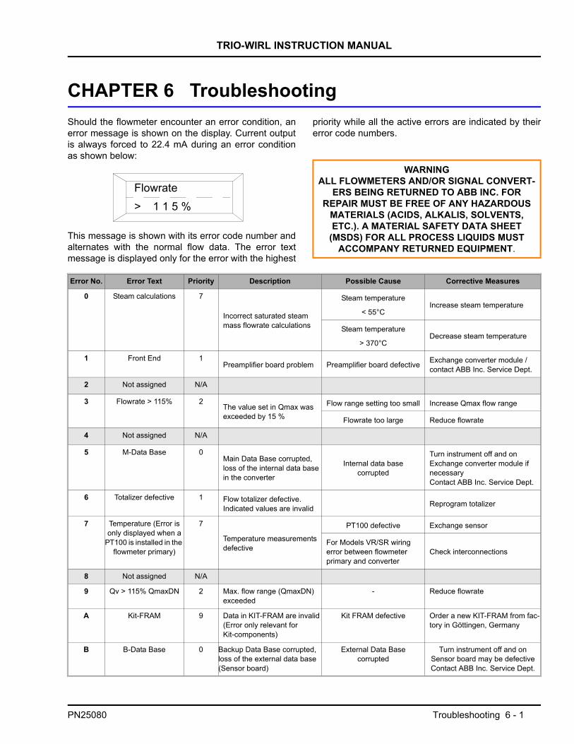
TRIO-WIRL INSTRUCTION MANUAL
CHAPTER 6 TroubleshootingShould the flowmeter encounter an error condition, anerror message is shown on the display. Current outputis always forced to 22.4 mA during an error conditionas shown below:
This message is shown with its error code number andalternates with the normal flow data. The error textmessage is displayed only for the error with the highest
priority while all the active errors are indicated by theirerror code numbers.
Flowrate> 1 1 5 %
WARNINGALL FLOWMETERS AND/OR SIGNAL CONVERT-
ERS BEING RETURNED TO ABB INC. FOR REPAIR MUST BE FREE OF ANY HAZARDOUS
MATERIALS (ACIDS, ALKALIS, SOLVENTS, ETC.). A MATERIAL SAFETY DATA SHEET
(MSDS) FOR ALL PROCESS LIQUIDS MUST ACCOMPANY RETURNED EQUIPMENT.
Error No. Error Text Priority Description Possible Cause Corrective Measures
0 Steam calculations 7
Incorrect saturated steam mass flowrate calculations
Steam temperature
< 55°CIncrease steam temperature
Steam temperature
> 370°CDecrease steam temperature
1 Front End 1Preamplifier board problem Preamplifier board defective Exchange converter module /
contact ABB Inc. Service Dept.
2 Not assigned N/A
3 Flowrate > 115% 2The value set in Qmax was exceeded by 15 %
Flow range setting too small Increase Qmax flow range
Flowrate too large Reduce flowrate
4 Not assigned N/A
5 M-Data Base 0Main Data Base corrupted, loss of the internal data base in the converter
Internal data base corrupted
Turn instrument off and onExchange converter module if necessaryContact ABB Inc. Service Dept.
6 Totalizer defective 1 Flow totalizer defective. Indicated values are invalid Reprogram totalizer
7 Temperature (Error is only displayed when a
PT100 is installed in the flowmeter primary)
7
Temperature measurements defective
PT100 defective Exchange sensor
For Models VR/SR wiring error between flowmeterprimary and converter
Check interconnections
8 Not assigned N/A
9 Qv > 115% QmaxDN 2 Max. flow range (QmaxDN) exceeded
- Reduce flowrate
A Kit-FRAM 9 Data in KIT-FRAM are invalid (Error only relevant for Kit-components)
Kit FRAM defective Order a new KIT-FRAM from fac-tory in Göttingen, Germany
B B-Data Base 0 Backup Data Base corrupted, loss of the external data base (Sensor board)
External Data Base corrupted
Turn instrument off and onSensor board may be defective Contact ABB Inc. Service Dept.
PN25080 Troubleshooting 6 - 1

TRIO-WIRL INSTRUCTION MANUAL
CHAPTER 7 Parts List
7.1 Replacement PartsThe following pages show a cutaway view of the flowmeters and indicate replacement parts that are available forthe meters along with their ABB Inc. ordering numbers.
PN25080 Parts List 7 - 1

Parts List
TRIO
-WIR
L INSTR
UC
TION
MA
NU
AL
REF.
7 - 2
PN25080
FIGU
RE 7-1 FLO
WM
ETER/SIG
NA
L CO
NVER
TER PA
RTS
(REFER
TO TA
BLE 7-1 FO
R O
RD
ERIN
G IN
FOR
MA
TION
)

TRIO-WIRL INSTRUCTION MANUAL
7.1.1 Flowmeter/Signal Converter PartsRefer to Figure 7-1 for location of item numbers.
TABLE 7-1. FLOWMETER/SIGNAL CONVERTER PARTS LIST
ITEM QTY. DESCRIPTION PART NUMBER
1 1
SENSOR
Stainless Steel:
Sensor w/Remote ElectronicsSensor w/PT100 w/Remote ElectronicsSensor w/Integral ElectronicsSensor w/PT100 w/Integral Electronics
Hastelloy C:
Sensor w/Remote ElectronicsSensor w/PT100 w/Remote ElectronicsSensor w/Integral ElectronicsSensor w/PT100 w/Integral Electronics
D693B042U06D693B043U06D693B042U14D693B043U14
D693B042U07D693B043U07D693B042U15D693B043U15
2 1
SENSOR O-RINGO-Ring, KalrezO-Ring, VitonO-Ring, PTFE
102E077U56101W709U01101C709U01
3 1 TOWER ASSEMBLY 612A708U01
3A 1 SET SCREWSSpare set-screws, Tower Assembly D020J106AU20
4 1
ADAPTERAdapter, PlainAdapter, Bartek w/3-Wire Std. SensorAdapter, Bartek w/5-Wire Std. Sensor w/PT100
D633A043U01D633A043U02D633A043U03
5 1 Anti-Rotation Dress BoltM5 x 25 Screw, Hex Sock. Hd., DIN912
D395A006U0109H116AU20
6
1114215511
HOUSING ASSEMBLYBodySensor Connection BoardConnection Board (Customer Side)Feed-ThroughGround-Connection PlatesM4 x 10mm Cheese Hd Screw, DIN84M4 x 8 Phillips, Phillister Hd. ScrewM4 Split Lock-Washer, DIN 1271/2 Hex Socket, Pipi-Plug, 316 SSPipe-Plug, 1/2-14 NPT, Ploy.
D670A026U03D685A899U03D685A903U03D634A029U01D405B086U0102G108AU2004G107AU2085C021EU20112A352U21114B081U03
7 1FRONT COVER WITH EX-PROOF GLASS & O-RINGCoverO-Ring
D612A162U021951779A042
PN25080 Parts List 7 - 3
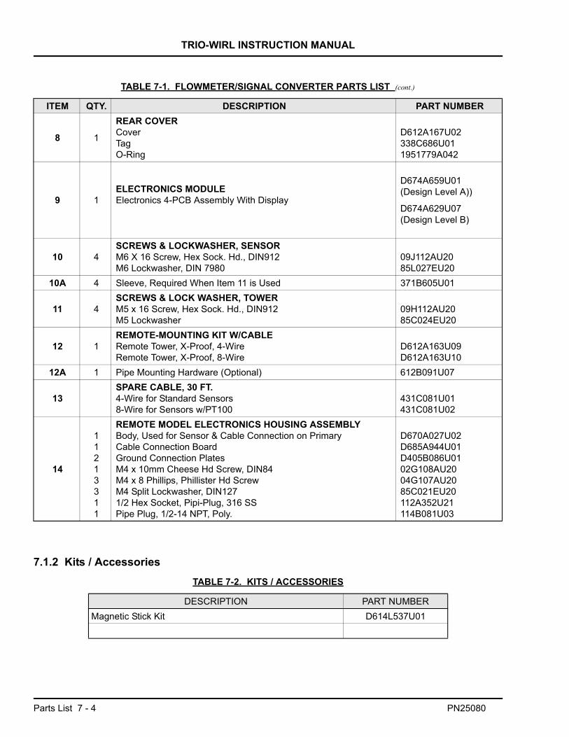
TRIO-WIRL INSTRUCTION MANUAL
7.1.2 Kits / Accessories
ITEM QTY. DESCRIPTION PART NUMBER
8 1
REAR COVERCoverTagO-Ring
D612A167U02338C686U011951779A042
9 1ELECTRONICS MODULEElectronics 4-PCB Assembly With Display
D674A659U01(Design Level A))
D674A629U07(Design Level B)
10 4SCREWS & LOCKWASHER, SENSORM6 X 16 Screw, Hex Sock. Hd., DIN912M6 Lockwasher, DIN 7980
09J112AU2085L027EU20
10A 4 Sleeve, Required When Item 11 is Used 371B605U01
11 4SCREWS & LOCK WASHER, TOWERM5 x 16 Screw, Hex Sock. Hd., DIN912M5 Lockwasher
09H112AU2085C024EU20
12 1REMOTE-MOUNTING KIT W/CABLERemote Tower, X-Proof, 4-WireRemote Tower, X-Proof, 8-Wire
D612A163U09D612A163U10
12A 1 Pipe Mounting Hardware (Optional) 612B091U07
13SPARE CABLE, 30 FT.4-Wire for Standard Sensors8-Wire for Sensors w/PT100
431C081U01431C081U02
14
11213311
REMOTE MODEL ELECTRONICS HOUSING ASSEMBLYBody, Used for Sensor & Cable Connection on PrimaryCable Connection BoardGround Connection PlatesM4 x 10mm Cheese Hd Screw, DIN84M4 x 8 Phillips, Phillister Hd ScrewM4 Split Lockwasher, DIN1271/2 Hex Socket, Pipi-Plug, 316 SSPipe Plug, 1/2-14 NPT, Poly.
D670A027U02D685A944U01D405B086U0102G108AU2004G107AU2085C021EU20112A352U21114B081U03
TABLE 7-1. FLOWMETER/SIGNAL CONVERTER PARTS LIST (cont.)
TABLE 7-2. KITS / ACCESSORIES
DESCRIPTION PART NUMBERMagnetic Stick Kit D614L537U01
Parts List 7 - 4 PN25080

TRIO-WIRL INSTRUCTION MANUAL
TABLE 7-3. CENTERING DEVICES, VORTEX WAFER
DESCRIPTION PART NUMBER
Centering Devices,
Wafer-Style Meter
SIZE [in.] ANSI FLANGE RATING [lb]
1150
376D055U07300
1-1/2150
376D055U03300
2150
376D056U01300
3150 430E014U01300 430E014U10
4150 430E014U05300 430E014U11
6150 430E014U08300 430E014U14
8150 430E014U09300 430E014U20
TABLE 7-4. METER MOUNTING KITS, VORTEX WAFER
DESCRIPTION PART NUMBER
Mounting Kits, Wafer-Style Meter
[Includes Studs, Nuts, Gaskets and Centering Devices]
SIZE ANSI FLANGE RATING [lb]
1150 614B656U85
300, 600 614B656U86
1-1/2150 614B656U16300 614B656U17600 614B656U18
2150 614B656U12300 614B656U13600 614B656U14
3150 614B656U01
300, 600 614B656U02
4150 614B656U03300 614B656U04600 614B656U05
6150 614B656U06300 614B656U07600 614B656U08
8150 614B656U09300 614B656U10600 614B656U11
PN25080 Parts List 7 - 5

TRIO-WIRL INSTRUCTION MANUAL
7.1.3 Flange Gaskets
* For higher process temperatures, refer to Figure 2-13 or 3-17 for Swirl and Vortex respectively.
Specifications for KLINGERsil C-4401 gasket material:
Liquids:
Operating Temperature Limit: 750oF
Gases & Steam:
Operating Temperature Limit: 450oF
Notes:
* Different O-Ring materials may be required for highprocess temperature applications
* Temperature limits are valid at internal pressures of< 400 psi
* The use of KLINGERexpert software system isrecommended for these extreme temperatureapplications.
TABLE 7-5. FLANGE GASKETS
METER SIZE ANSI FLANGERATING
(POUNDS)
MAX. PRESSURE *@ TProc < 68oF (20oC)
( PSI )QTY.
PART NUMBER.
INCHES MM VORTEX SWIRL
1/2 15 150300
276725
2
333J089U01333J089U02
1 25 150300
276725
333J089U10333J089U11
1-1/4 32 150300
276725 N/A 333J089U68
333J089U69
1-1/2 40 150300
276725
333J089U15333J089U16
2 50 150300/600
276725/1436
333J089U19333J089U25
3 80 150300/600
276725/1436
333J089U22333J089U26
4 100150300
276725
333J089U29333J089U30
600 1436 N/A 333J083U28
6 150150300600
2767251436
333J083U33333J083U42333J083U43
8 200150300600
2767251436
333J083U38333J083U46333J083U47
10 250 150300
276725
333J083U54333J083U55 N/A
12 300 150300
276725
333J083U56333J083U57
16 400 150300
276725 N/A 333J083U58
333J083U59
Parts List 7 - 6 PN25080

The Company’s policy is one of continuous product improvement and theright is reserved to modify the information contained herein without notice.
© 2003 ABB Inc. Printed in USA
ABB Instrumentation S.p.AVia Sempione 24320016 Pero (Milano) ItalyTel: +39 (02) 33928 1Fax: +39 (02) 33928 240
ABB Instrumentation LtdHoward Road, St. NeotsCambs. England, PE19 3EUTel. +44 (0) 1480-475-321FAX: +44 (0) 1480-217-948
ABB Inc.Instrumentation Division125 East County Line RoadWarminster, PA 18974 USATel. 215-674-6000FAX: 215-674-7183
ABB Automation Products GmbHIndustriestr. 28D-65760 Eschborn GermanyTel: +49 (0) 6196 800 0Fax: +49 (0) 6196 800 1849
PN25
080