Instrucciones para soldar antena wifi al AR.Drone
12
AR.Drone 2 - Main Board – External Antenna Modification Procedure Document Number: EAM-20130303-2 Check back for updates. 3/22/2013
-
Upload
jhony-larico -
Category
Documents
-
view
14 -
download
4
description
Este tutorial es sólo para expertos que saben lo que hacen. Es una modificación muy invasiva y perderás tu garantía completamente en el momento de realizarla. Solo es necesario si quieres extender el alcance wifi de tu ar-drone mas allá de los 500 metros.
Transcript of Instrucciones para soldar antena wifi al AR.Drone
AR.Drone 2 - Main Board – External Antenna Modification Procedure Document Number: EAM-20130303-2
Check back for updates.
3/22/2013
DroneMod.com AR.Drone 2 - Main Board – External Antenna Modification Procedure
1 Document Number: EAM-20130303-2 Mar 22nd, 2013
NOTE: Along with this mod procedure, you will also need to:
1. Remove the Main Board. Refer to the Main Board Removal Procedure 2. Adapt the Wheel Antenna PCB with an MMCX Female Jack Connector.
(Refer to the Wheel Antenna PCB MMCX Connector Installation Procedure)
3. Install an Antenna: (Refer to the Antenna Mount Installation Procedure)
a. Wheel Antenna Mast (highly preferred) b. RP-SMA Antenna Mast (which is interchangeable with a wheel mast) c. Bottom Mount Wheel Antenna (can upgrade to a mast later)
See the DroneMod.com “How To” section for other details.
Require Tools:
1. Razor Knife (x-acto type). Use a new blade
2. Wire Snips. Make sure the jaw tips are in newer condition
3. A decent work surface: avoid static charge build up
4. Soldering Iron with a small tip
5. Magnifying Lamp; at least have good lighting and a magnifier loop
6. A small electronics bench vise is optional but very handy
7. An Ohm Meter is highly recommended to ensure RF trace continuity
8. Another person; to hold the MMCX connector in place as it is being
soldered to the Main Board
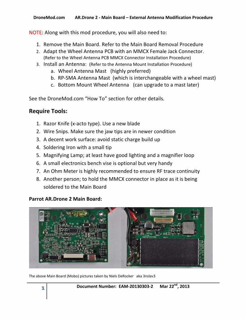
Parrot AR.Drone 2 Main Board:
The above Main Board (Mobo) pictures taken by Niels DeRocker aka 3nslav3
DroneMod.com AR.Drone 2 - Main Board – External Antenna Modification Procedure
2 Document Number: EAM-20130303-2 Mar 22nd, 2013
Check List
Print out and use this checklist to ensure every step is taken in the correct order.
Not complete. Will finalize this checklist on the next pass.
Step 1:
Step 2:
Step 3:
Step 4:
Step 5:
Step 6:
Step 7:
Step 8:
Step 9:
Step 10:
Step 11:
DroneMod.com AR.Drone 2 - Main Board – External Antenna Modification Procedure
3 Document Number: EAM-20130303-2 Mar 22nd, 2013
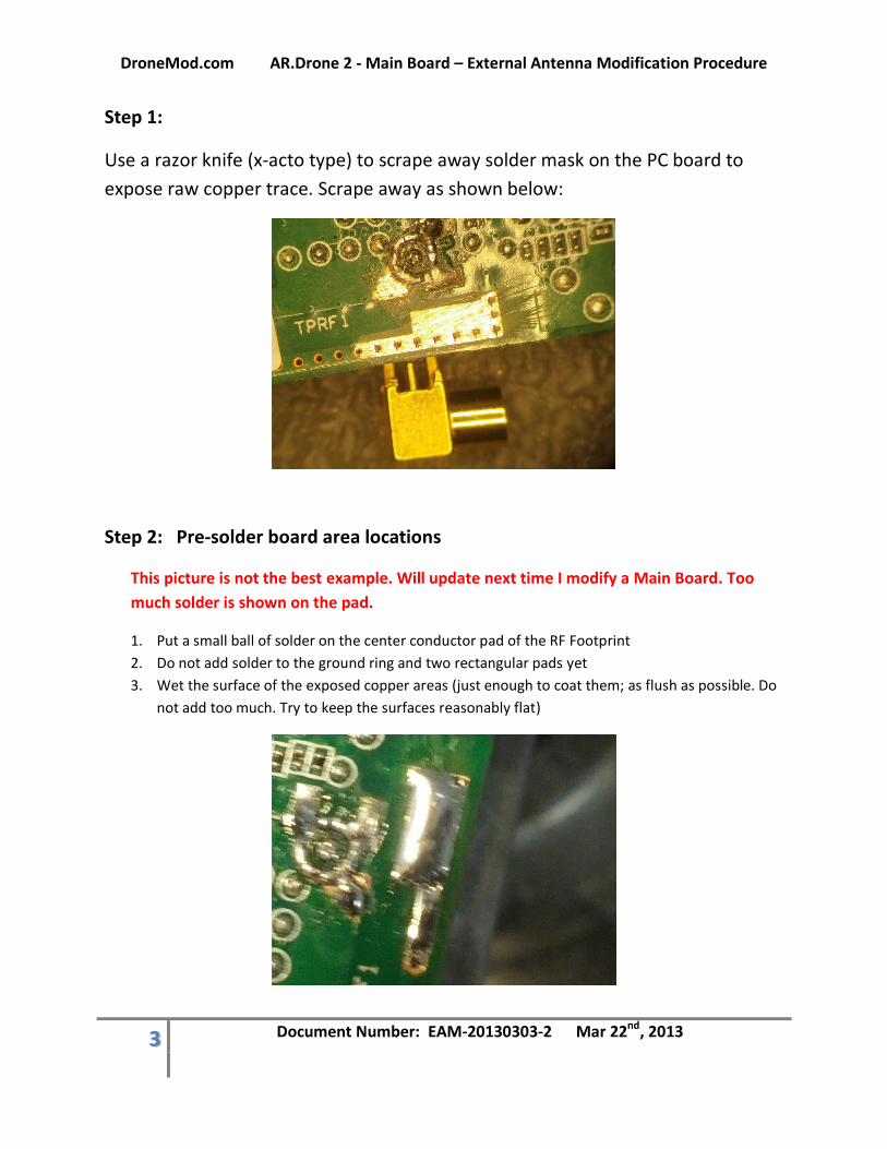
Step 1:
Use a razor knife (x-acto type) to scrape away solder mask on the PC board to
expose raw copper trace. Scrape away as shown below:
Step 2: Pre-solder board area locations
This picture is not the best example. Will update next time I modify a Main Board. Too
much solder is shown on the pad.
1. Put a small ball of solder on the center conductor pad of the RF Footprint
2. Do not add solder to the ground ring and two rectangular pads yet
3. Wet the surface of the exposed copper areas (just enough to coat them; as flush as possible. Do
not add too much. Try to keep the surfaces reasonably flat)
DroneMod.com AR.Drone 2 - Main Board – External Antenna Modification Procedure
4 Document Number: EAM-20130303-2 Mar 22nd, 2013
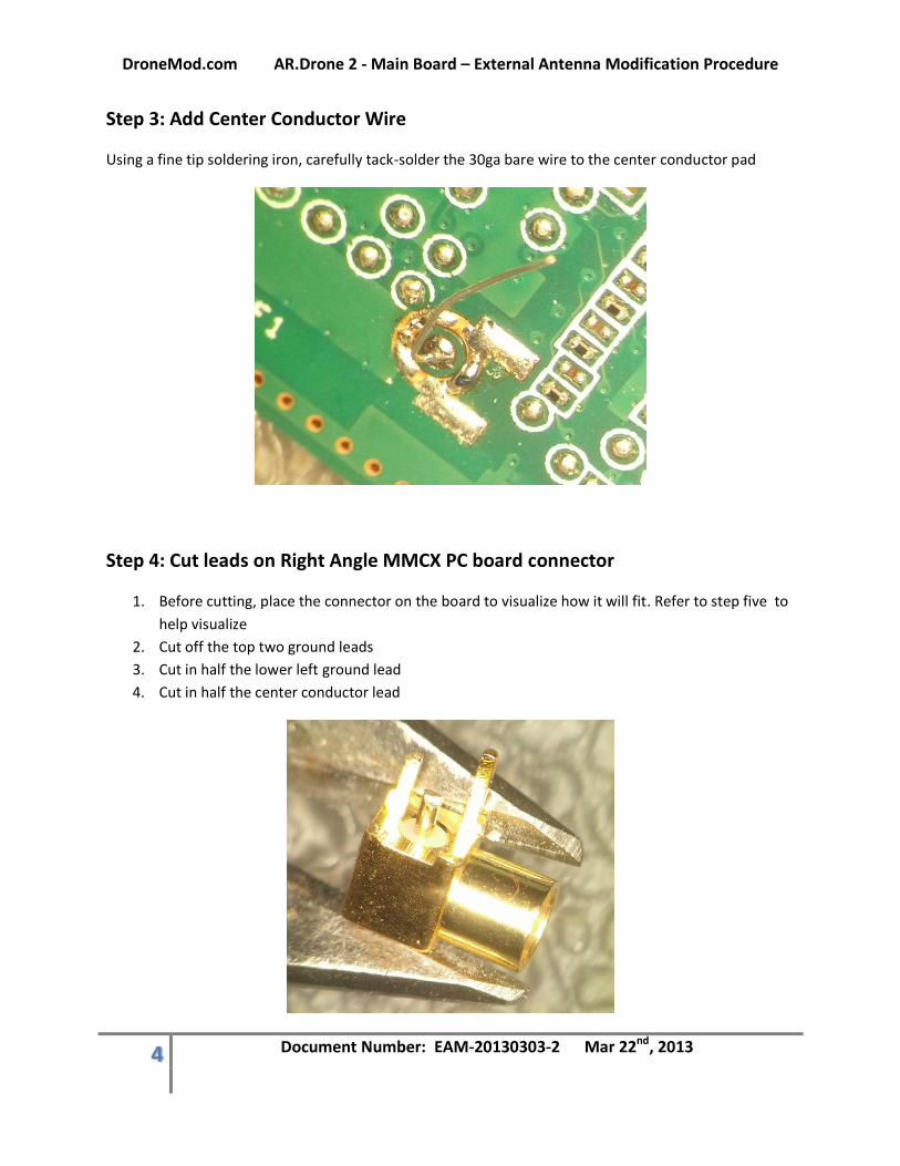
Step 3: Add Center Conductor Wire
Using a fine tip soldering iron, carefully tack-solder the 30ga bare wire to the center conductor pad
Step 4: Cut leads on Right Angle MMCX PC board connector
1. Before cutting, place the connector on the board to visualize how it will fit. Refer to step five to
help visualize
2. Cut off the top two ground leads
3. Cut in half the lower left ground lead
4. Cut in half the center conductor lead
DroneMod.com AR.Drone 2 - Main Board – External Antenna Modification Procedure
5 Document Number: EAM-20130303-2 Mar 22nd, 2013
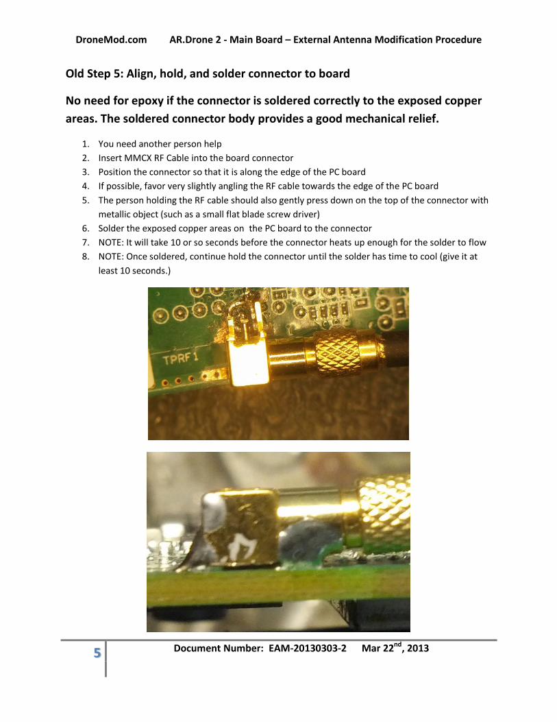
Old Step 5: Align, hold, and solder connector to board
No need for epoxy if the connector is soldered correctly to the exposed copper
areas. The soldered connector body provides a good mechanical relief.
1. You need another person help
2. Insert MMCX RF Cable into the board connector
3. Position the connector so that it is along the edge of the PC board
4. If possible, favor very slightly angling the RF cable towards the edge of the PC board
5. The person holding the RF cable should also gently press down on the top of the connector with
metallic object (such as a small flat blade screw driver)
6. Solder the exposed copper areas on the PC board to the connector
7. NOTE: It will take 10 or so seconds before the connector heats up enough for the solder to flow
8. NOTE: Once soldered, continue hold the connector until the solder has time to cool (give it at
least 10 seconds.)
DroneMod.com AR.Drone 2 - Main Board – External Antenna Modification Procedure
6 Document Number: EAM-20130303-2 Mar 22nd, 2013
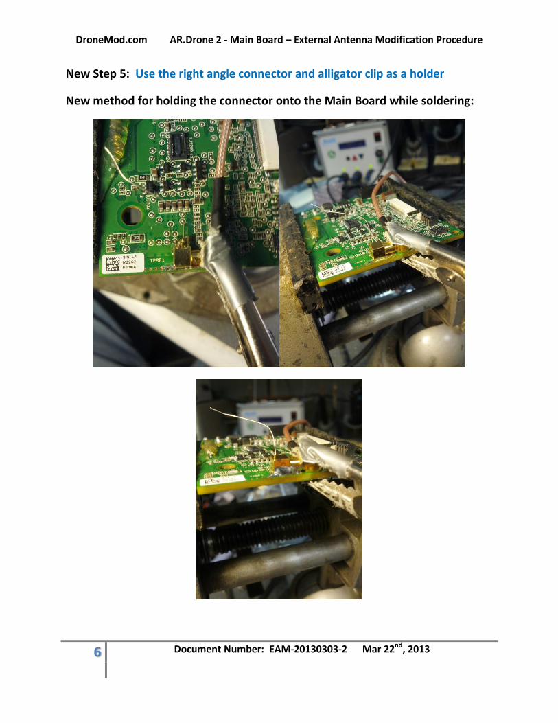
New Step 5: Use the right angle connector and alligator clip as a holder
New method for holding the connector onto the Main Board while soldering:
DroneMod.com AR.Drone 2 - Main Board – External Antenna Modification Procedure
7 Document Number: EAM-20130303-2 Mar 22nd, 2013
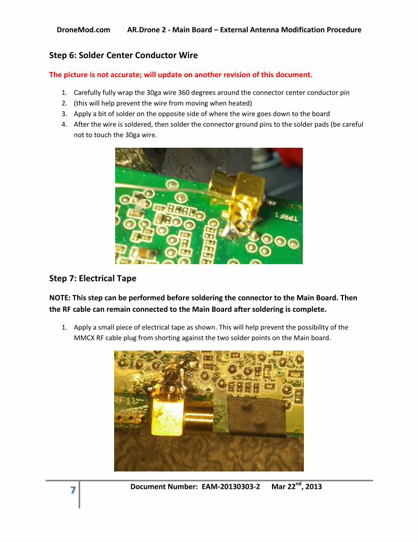
Step 6: Solder Center Conductor Wire
The picture is not accurate; will update on another revision of this document.
1. Carefully fully wrap the 30ga wire 360 degrees around the connector center conductor pin
2. (this will help prevent the wire from moving when heated)
3. Apply a bit of solder on the opposite side of where the wire goes down to the board
4. After the wire is soldered, then solder the connector ground pins to the solder pads (be careful
not to touch the 30ga wire.
Step 7: Electrical Tape
NOTE: This step can be performed before soldering the connector to the Main Board. Then
the RF cable can remain connected to the Main Board after soldering is complete.
1. Apply a small piece of electrical tape as shown. This will help prevent the possibility of the
MMCX RF cable plug from shorting against the two solder points on the Main board.
DroneMod.com AR.Drone 2 - Main Board – External Antenna Modification Procedure
8 Document Number: EAM-20130303-2 Mar 22nd, 2013
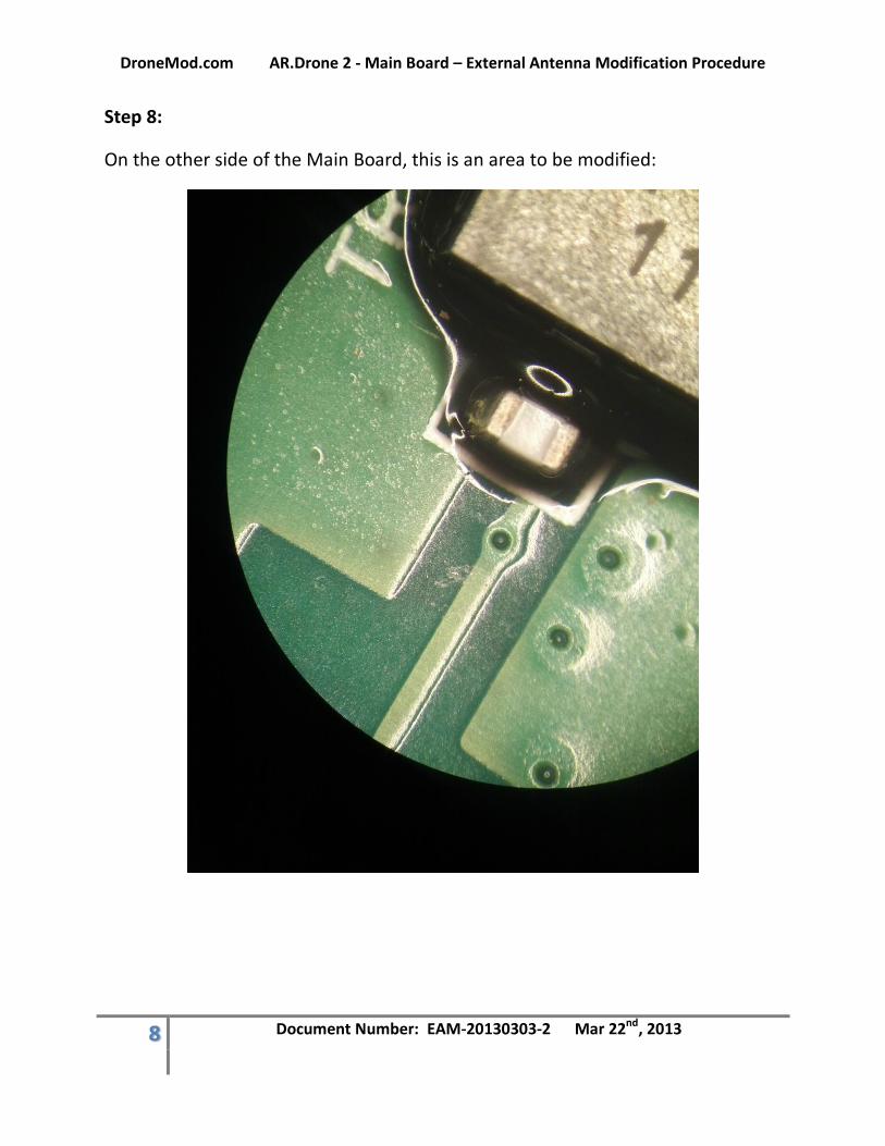
Step 8:
On the other side of the Main Board, this is an area to be modified:
DroneMod.com AR.Drone 2 - Main Board – External Antenna Modification Procedure
9 Document Number: EAM-20130303-2 Mar 22nd, 2013
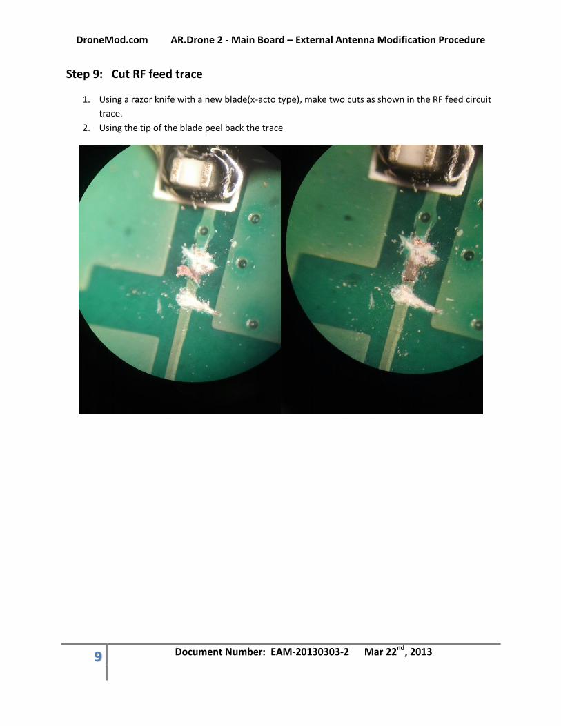
Step 9: Cut RF feed trace
1. Using a razor knife with a new blade(x-acto type), make two cuts as shown in the RF feed circuit
trace.
2. Using the tip of the blade peel back the trace
DroneMod.com AR.Drone 2 - Main Board – External Antenna Modification Procedure
10 Document Number: EAM-20130303-2 Mar 22nd, 2013
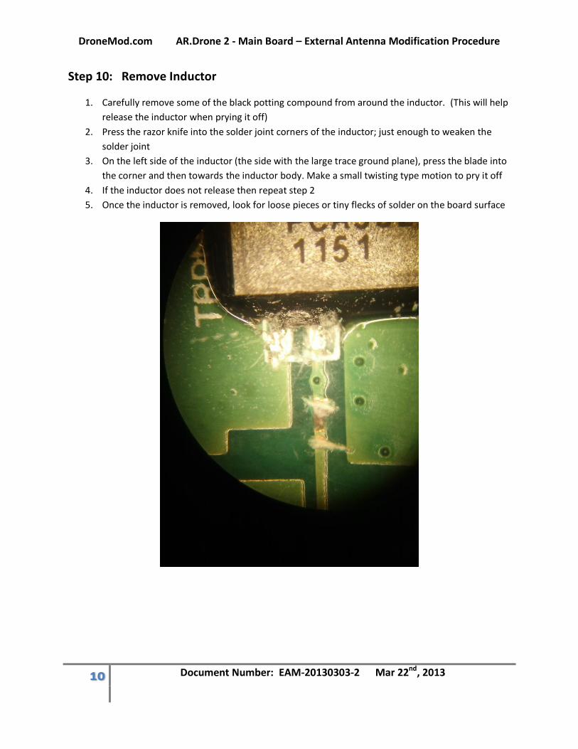
Step 10: Remove Inductor
1. Carefully remove some of the black potting compound from around the inductor. (This will help
release the inductor when prying it off)
2. Press the razor knife into the solder joint corners of the inductor; just enough to weaken the
solder joint
3. On the left side of the inductor (the side with the large trace ground plane), press the blade into
the corner and then towards the inductor body. Make a small twisting type motion to pry it off
4. If the inductor does not release then repeat step 2
5. Once the inductor is removed, look for loose pieces or tiny flecks of solder on the board surface
DroneMod.com AR.Drone 2 - Main Board – External Antenna Modification Procedure
11 Document Number: EAM-20130303-2 Mar 22nd, 2013
Step 11: Ohm Meter Check
Only after the above steps, then check to ensure proper continuity (opens and shorts):
1. Measure from the MMCX center pin to the MMCX connector shell. There should be no
continuity (an open). If a short is found, check the MMCX center pin solder area first; then the
inductor area. Good lighting and a magnifier will assist spotting problems
2. Measure from the MMCX center pin to the RF feed inductor pad on the other side of the board.
There should be continuity (a short). If an open is found, then check the MMCX center pin wire
is soldered property the pad on the Main Board