installation, start-up, 355MAV and operating instructions
52
NOTE: Read the entire instruction manual before starting the installation. This symbol → indicates a change since the last issue. Index Page SAFETY CONSIDERATIONS .....................................................2 DIMENSIONAL DRAWING........................................................3 Clearances to Combustibles......................................................4 CODES AND STANDARDS........................................................5 ELECTROSTATIC DISCHARGE (ESD) PRECAUTIONS........5 INTRODUCTION ..........................................................................6 APPLICATIONS............................................................................6 General ......................................................................................6 Upflow Applications .................................................................6 Downflow Applications ............................................................8 Horizontal Left (Supply-Air Discharge) Applications ..........10 Horizontal Right (Supply-Air Discharge) Applications ........12 LOCATION..................................................................................13 General ....................................................................................13 Low-Heat Only Installation ....................................................14 Furnace Location Relative to Cooling Equipment ................15 Hazardous Locations...............................................................15 INSTALLATION .........................................................................15 Leveling Legs (If Desired) .....................................................15 Installation In Upflow or Downflow Applications ................15 Installation In Horizontal Applications ..................................17 Air Ducts .................................................................................18 General Requirements .......................................................18 Ductwork Acoustical Treatment .......................................18 Supply Air Connections ....................................................18 Return Air Connections.....................................................18 Filter Arrangement ..................................................................18 Bottom Closure Panel .............................................................19 Gas Piping ...............................................................................19 Electrical Connections ............................................................20 115-v Wiring......................................................................20 24-v Wiring........................................................................22 Accessories ........................................................................22 Direct Venting.........................................................................22 Removal of Existing Furnaces from Common Vent Systems................................................22 Combustion-Air and Vent Piping .....................................25 Concentric Vent and Combustion-Air Termination Kit Installation ..............................................................31 Multiventing and Vent Terminations ................................34 Condensate Drain ....................................................................34 General ...............................................................................34 Application.........................................................................34 Condensate Drain Protection.............................................35 START-UP, ADJUSTMENTS AND SAFETY CHECK......35 General ...............................................................................35 Select Setup Switch Positions ...........................................36 Prime Condensate Trap With Water .................................37 Purge Gas Lines ................................................................37 Sequence of Operation ......................................................37 Single-Stage Thermostat and Two-Stage Heating (Adaptive Mode) ..........................................................37 Two-Stage Thermostat and Two-Stage Heating .........39 Cooling Mode...............................................................39 Thermidistat Mode .......................................................40 Super-Dehumidify Mode..............................................40 Continuous Blower Mode ............................................40 Heat Pump ....................................................................41 Component Test ...........................................................41 Adjustments .......................................................................41 Set Gas Input Rate .......................................................41 Set Temperature Rise ...................................................48 Set Thermostat Heat Anticipator .................................49 A93040 ama CERTIFIED ® REGISTERED ISO 9001:2000 As an ENERGY STAR® Partner, Bryant Heating & Cooling Systems has de- termined that this product meets the ENERGY STAR® guidelines for en- ergy efficiency. Fig. 1—Multipoise Orientations A93041 UPFLOW DOWNFLOW HORIZONTAL LEFT AIRFLOW AIRFLOW AIRFLOW AIRFLOW HORIZONTAL RIGHT installation, start-up, and operating instructions DELUXE 4-WAY MULTIPOISE VARIABLE-CAPACITY DIRECT-VENT CONDENSING GAS FURNACE Cancels: II 355M-40-13 II 355M-40-14 3-05 355MAV Series I —1—
Transcript of installation, start-up, 355MAV and operating instructions

NOTE: Read the entire instruction manual before starting theinstallation.This symbol → indicates a change since the last issue.Index PageSAFETY CONSIDERATIONS .....................................................2DIMENSIONAL DRAWING........................................................3
Clearances to Combustibles......................................................4CODES AND STANDARDS........................................................5ELECTROSTATIC DISCHARGE (ESD) PRECAUTIONS........5INTRODUCTION..........................................................................6APPLICATIONS............................................................................6
General ......................................................................................6Upflow Applications.................................................................6Downflow Applications ............................................................8Horizontal Left (Supply-Air Discharge) Applications ..........10Horizontal Right (Supply-Air Discharge) Applications ........12
LOCATION..................................................................................13General ....................................................................................13Low-Heat Only Installation ....................................................14Furnace Location Relative to Cooling Equipment ................15Hazardous Locations...............................................................15
INSTALLATION .........................................................................15Leveling Legs (If Desired) .....................................................15Installation In Upflow or Downflow Applications................15Installation In Horizontal Applications ..................................17Air Ducts.................................................................................18
General Requirements .......................................................18Ductwork Acoustical Treatment .......................................18Supply Air Connections ....................................................18Return Air Connections.....................................................18
Filter Arrangement..................................................................18Bottom Closure Panel.............................................................19Gas Piping...............................................................................19Electrical Connections ............................................................20
115-v Wiring......................................................................2024-v Wiring........................................................................22Accessories ........................................................................22
Direct Venting.........................................................................22Removal of Existing Furnaces from
Common Vent Systems................................................22Combustion-Air and Vent Piping .....................................25Concentric Vent and Combustion-Air Termination
Kit Installation..............................................................31Multiventing and Vent Terminations................................34
Condensate Drain....................................................................34
General...............................................................................34Application.........................................................................34Condensate Drain Protection.............................................35
START-UP, ADJUSTMENTS AND SAFETY CHECK......35General...............................................................................35Select Setup Switch Positions...........................................36Prime Condensate Trap With Water.................................37Purge Gas Lines ................................................................37Sequence of Operation ......................................................37
Single-Stage Thermostat and Two-Stage Heating(Adaptive Mode) ..........................................................37Two-Stage Thermostat and Two-Stage Heating .........39Cooling Mode...............................................................39Thermidistat Mode .......................................................40Super-Dehumidify Mode..............................................40Continuous Blower Mode ............................................40Heat Pump....................................................................41Component Test ...........................................................41
Adjustments .......................................................................41Set Gas Input Rate .......................................................41Set Temperature Rise...................................................48Set Thermostat Heat Anticipator .................................49
A93040
ama CERTIFIED®
REGISTERED
ISO 9001:2000
As an ENERGY STAR®Partner, Bryant Heating &Cooling Systems has de-termined that this productmeets the ENERGYSTAR® guidelines for en-ergy efficiency.
Fig. 1—Multipoise OrientationsA93041
UPFLOW
DOWNFLOW
HORIZONTALLEFT
AIRFLOW AIRFLOW
AIRFLOW
AIRFLOW
HORIZONTALRIGHT
installation, start-up,and operating instructionsDELUXE 4-WAY MULTIPOISEVARIABLE-CAPACITY DIRECT-VENTCONDENSING GAS FURNACE
Cancels: II 355M-40-13 II 355M-40-143-05
355MAVSeries I
—1—
Check Safety Controls.......................................................49Check Primary Limit Control ......................................49Check Pressure Switch.................................................49
CHECKLIST......................................................................49
SAFETY CONSIDERATIONS
CAUTION: FURNACE RELIABILITY HAZARDImproper installation or misapplication of furnace mayrequire excessive servicing or cause premature compo-nent failure.Application of this furnace should be indoors with specialattention given to vent sizing and material, gas input rate,air temperature rise, unit leveling, and unit sizing.
WARNING: FIRE, EXPLOSION, ELECTRICALSHOCK AND CARBON MONOXIDE POISONINGHAZARDFailure to follow this warning could result in electricalshock, fire, personal injury, or death.Improper installation, adjustment, alteration, service,maintenance, or use can cause carbon monoxide poison-ing, explosion, tire, electrical shock, or other conditionswhich may cause personal injury or property damage.Consult a qualified installer, service agency, local gassupplier, or your distributor or branch for information orassistance. The qualified installer or agency must useonly factory-authorized and listed kits or accessorieswhen modifying this product.
Installing and servicing heating equipment can be hazardous due togas and electrical components. Only trained and qualifiedpersonnel should install, repair, or service heating equipment.Untrained personnel can perform basic maintenance functionssuch as cleaning and replacing air filters. All other operations mustbe performed by trained service personnel. When working onheating equipment, observe precautions in literature, on tags, andon labels attached to or shipped with unit and other safetyprecautions that may apply.
These instructions cover the minimum requirements and conformto existing national standards and safety codes. In some instances,these instructions exceed certain local codes and ordinances,especially those that may not have kept up with changing residen-tial construction practices. We require these instructions as aminimum for a safe installation.
Wear safety glasses and work gloves. Have a fire extinguisheravailable during start-up and adjustment procedures and servicecalls.
Recognize safety information. This is the safety-alert symbol .When you see this symbol on the unit and in instructions ormanuals, be alert to the potential for personal injury.
Understand these signal words: DANGER, WARNING, andCAUTION. These words are used with the safety-alert symbol.DANGER identifies the most serious hazards which will result insevere personal injury or death. WARNING signifies hazardswhich could result in personal injury or death. CAUTION is usedto identify unsafe practices which may result in minor personalinjury or product and property damage. NOTE is used to highlightsuggestions which will result in enhanced installation, reliability,or operation.
CAUTION: CUT HAZARDFailure to follow this caution may result in personalinjury.Sheet metal parts may have sharp edges or burrs. Use careand wear appropriate protective clothing and gloves whenhandling parts.
The 355MAV Multipoise Condensing Gas-Fired Furnaces areCSA (formerly AGA and CGA) design-certified for natural andpropane gases (see furnace rating plate) and for installation inalcoves, attics, basements, closets, utility rooms, crawlspaces, andgarages. The furnace is factory-shipped for use with natural gas. ACSA listed gas conversion kit is required to convert furnace for usewith propane gas.
See Fig. 3 for required clearances to combustibles.
Maintain a 1-in. clearance from combustible materials to supply airductwork for a distance of 36 inches horizontally from the furnace.See NFPA 90B or local code for further requirements.
These furnaces SHALL NOT be installed directly on carpeting,tile, or any other combustible material other than wood flooring. Indownflow installations, factory accessory floor base MUST beused when installed on combustible materials and wood flooring.Special base is not required when this furnace is installed onmanufacturer’s Coil Assembly Part No. CD5 or CK5, or when CoilBox Part No. KCAKC is used. These furnaces are suitable forinstallation in a structure built on site or a manufactured buildingcompleted at final site. The design of this furnace line is NOT CSAdesign-certified for installation in recreation vehicles, manufac-tured (mobile) homes or outdoors.
This furnace is designed for continuous return-air minimumtemperature of 60°F db or intermittent operation down to 55°F dbsuch as when used with a night setback thermometer. Return-airtemperature must not exceed 80°F db. Failure to follow thesereturn air limits may affect reliability of heat exchangers, motorsand controls. (See Fig. 4.)
These furnaces are shipped with the drain and pressure tubesconnected for UPFLOW applications. Minor modifications arerequired when used in DOWNFLOW, HORIZONTAL RIGHT, orHORIZONTAL LEFT (supply-air discharge direction) applica-tions as shown in Fig. 1. See details in Applications section.Install this furnace only in a location and position as specified inLOCATION and INSTALLATION sections of these instructions.Combustion products must be discharged outdoors. Connect thisfurnace to an approved vent system only, as specified in theCombustion Air and Vent piping sections of these instructions.Never test for gas leaks with an open flame. Use a commerciallyavailable soap solution made specifically for the detection of leaksto check all connections as specified in the GAS PIPING sectionof these instructions.Always install furnace to operate within the furnace’s intended riserange with a duct system which has an external static pressurewithin the allowable range as specified in the SET TEMPERA-TURE RISE section of these instructions.When a furnace is installed so that the supply ducts carry aircirculated by the furnace to areas outside the space containing thefurnace, the return air must also be handled by a duct(s) sealed tothe furnace casing and terminating outside the space containing thefurnace.A gas-fired furnace for installation in a residential garage must beinstalled as specified in the Hazardous Locations section and Fig.5 of these instructions.The furnace is not to be used for temporary heating of buildings orstructures under construction unless the furnace installation andoperation complies with first CAUTION in the LOCATIONsection of these instructions.
—2—
→
→
→
→

Fig
.2—
Dim
ensi
on
alD
raw
ing
DIM
EN
SIO
NS
(IN
.)
UN
ITS
IZE
AD
E04
2040
*24
-1/2
*22
-7/8
*23
*04
2060
17-1
/215
-7/8
1604
2080
2119
-3/8
19-1
/206
0080
2119
-3/8
19-1
/206
0100
2119
-3/8
19-1
/206
0120
24-1
/222
-7/8
23
*T
hese
dim
ensi
ons
refle
ctth
ew
ider
casi
ngfo
rth
eT
roph
y(9
6.6
perc
ent
AF
UE
)fu
rnac
e.
A99
112
NO
TES
:1.
Min
imum
ret
urn-
air
open
ings
at f
urna
ce, b
ased
on
met
al d
uct.
If fle
x du
ct is
use
d,se
e fle
x du
ct m
anuf
actu
rer’s
rec
omm
enda
tions
for
equi
vale
nt d
iam
eter
s.2.
Min
imum
ret
urn-
air
open
ing
at fu
rnac
e:a.
For
800
CF
M–1
6-in
. rou
nd o
r 14
1 /2 x
12-
in. r
ecta
ngle
.b.
For
1200
CF
M–2
0-in
. rou
nd o
r 14
1 /2 x
191 /2
-in. r
ecta
ngle
.c.
For
1600
CF
M–2
2-in
. rou
nd o
r 14
1 /2 x
231 /4
-in. r
ecta
ngle
.d.
For
airf
low
req
uire
men
ts a
bove
180
0 C
FM
, see
Air
Del
iver
y ta
ble
in P
rodu
ct D
ata
liter
atur
e fo
r sp
ecifi
c us
e of
sin
gle
side
inle
ts. T
he u
se o
f bot
h si
de in
lets
, aco
mbi
natio
n of
1 s
ide
and
the
botto
m, o
r th
e bo
ttom
onl
y w
ill e
nsur
e ad
equa
tere
turn
air
open
ings
for
airf
low
req
uire
men
ts a
bove
180
0 C
FM
.
17 5 ⁄1
6"24 1 ⁄2
"27 9 ⁄1
6"T
YP
27 5 ⁄8
"29 11
⁄16"
TY
P
30 13
⁄16"32
5 ⁄8"
TY
P
33 1 ⁄4
"T
YP
CO
ND
EN
SAT
ED
RA
IN T
RA
PLO
CAT
ION
(ALT
ER
NAT
EU
PF
LOW
)
7 ⁄8-I
N. D
IAA
CC
ES
SO
RY
PO
WE
R E
NT
RY
7 ⁄8-I
N. D
IAP
OW
ER
CO
NN
CO
ND
EN
SAT
E D
RA
INT
RA
P L
OC
ATIO
N(D
OW
NF
LOW
&H
OR
IZO
NTA
L LE
FT
)
26 15
⁄16"
24 1 ⁄2
"
22 5 ⁄1
6"
2-IN
. CO
MB
US
TIO
N-
AIR
CO
NN
1 ⁄2-I
N. D
IAG
AS
CO
NN
2-IN
. VE
NT
CO
NN
1 ⁄2-I
N. D
IA T
HE
RM
OS
TAT
EN
TR
Y22
11⁄16
"
SID
E IN
LET
23 1 ⁄4
" T
YP
SID
E IN
LET
11 ⁄4"
1"
OU
TLE
T
26 15
⁄16"
28 1 ⁄2
"
22 5 ⁄1
6"
19"
13⁄16
"5 ⁄8
" 5 ⁄16"
1"
39 7 ⁄8
"
22 1 ⁄4
" T
YP
11⁄16
"
7 ⁄16"
24 3 ⁄1
6"B
OT
TOM
INLE
T
18 1 ⁄4
"
22 11
⁄16"
2-IN
. CO
MB
US
TIO
N-
AIR
CO
NN 1 ⁄2
-IN
. DIA
GA
S C
ON
N
7 ⁄8-I
N. D
IAP
OW
ER
CO
NN
1 ⁄2-I
N. D
IAT
HE
RM
OS
TAT
EN
TR
Y
2-IN
. VE
NT
CO
NN
DIM
PLE
LO
CAT
OR
SF
OR
HO
RIZ
ON
TAL
HA
NG
ING
14 1 ⁄2
"T
YP
SID
E IN
LET
9 7 ⁄1
6"T
YP
26 15
⁄16"
TY
P
CO
ND
EN
SAT
ED
RA
IN L
OC
ATIO
N(U
PF
LOW
)
30 1 ⁄2
"
9 ⁄16"
TY
P
CO
ND
EN
SAT
ED
RA
IN L
OC
ATIO
N(U
PF
LOW
)E
INLE
T
11/16
"11
/16"
D13
/16"
13/16
"
OU
TLE
T
A
AIR
FLO
W26
1 ⁄4"
26 1 ⁄4
"
CO
ND
EN
SAT
E D
RA
INT
RA
P L
OC
ATIO
N(D
OW
NF
LOW
&H
OR
IZO
NTA
L R
IGH
T)
OR
ALT
ER
NAT
E1 ⁄2
-IN
. DIA
GA
S C
ON
N
—3—

This furnace must be installed with a direct-vent (combustion airand flue) system and a factory accessory termination kit. In adirect-vent system, all air for combustion is taken directly from theoutside atmosphere and all flue products are discharged to theoutside atmosphere. See furnace and factory accessory terminationkit instructions for proper installation.
These furnaces are shipped with the following materials to assist inproper furnace installation. These materials are shipped in the mainblower compartment.
Fig. 3—Clearances to CombustiblesA04116
*
BO
TTO
MD
ES
SO
US
0"Ø
3"0"§
0"
TOP
/PLE
NU
MD
ES
SU
S/C
HA
MB
RE
D´A
IR
1"
0"§
24MIN
S I DE
C O T E SF R O N T
A V A N T
BC K
A R R I E
A
ER
S E R VIEC
LÈNTRTE
NEI
VANA
TFRONT
S I DE
C O T E S
F OUUF
RN A C SE EIA
RN
†
328068-201 REV. B (LIT TOP )
†
†
§
Ø
*
§Ø
*
1/2" MAX
FRONTFRONT
LEVEL (0")TO MIN 1/4" TO 1/2" MAX
INSTALLATION
UPFLOW ORDOWNFLOW
HORIZONTAL
MINIMUM INCHES CLEARANCE TO COMBUSTIBLE CONSTRUCTIONALL POSITIONS:
Minimum front clearance for service 24 inches (610mm).
For installation on combustible floors only when installed on special base No. KGASB0201ALL,Coil Assembly, Part No. CD5 or CK5, or Coil Casing, Part No. KCAKC.
Line contact is permissible only between lines formed by intersections of top and two sides of furnace jacket, and building joists, studs, or framing.Clearance shown is for air inlet and air outlet ends.120 and 140 size furnaces require 1 inch bottom clearance to combustible materials.
DOWNFLOW POSITIONS:
HORIZONTAL POSITIONS:
Dégagement avant minimum de 610mm (24 po) pour l'entretien.
POUR LA POSITION HORIZONTALE:
POUR LA POSITION COURANT DESCENDANT:
POUR TOUS LES POSITIONS:
DÉGAGEMENT MINIMUM EN POUCES AVEC ÉLÉMENTS DE CONSTRUCTION COMBUSTIBLES
Clearance in inchesDégagement (po).
Vent clearance to combustibles 0".
0 (po) Dégagement d´évent avec combustibles.
This furnace is approved for UPFLOW, DOWNFLOW andHORIZONTAL installations.
Clearance arrowsdo not change withfurnace orientation.
Pour l installation sur le plancher combustible seulement quand on utilise la base spéciale, pièce nº KGASB0201ALL, l ensemble serpentin, pièce nº CD5 ou CK5, ou le carter de serpentin, pièce nº KCAKC.
Le contact n´est permis qúentre les lignes formées par les intersections du dessus et desdeuxcôtés de la chemise de la fournaise, et des solives, des montants ou de la charpente dubátiment.La distance indiquée concerne l extrémité du tuyau d´arrivée d´air et l extrémité du tuyau de sortie d´air.Pour les fournaises de 120 et 140 taille, 1 po (25mm) dégagement des matériaux combusitblesest requis au-dessous.
This forced air furnace is equipped for use with natural gas at altitudes 0 - 10,000 ft (0 - 3,050m), except 140 size furnaces are only approved for altitudes 0 - 7,000 ft.(0 - 2,135m).An accessory kit, supplied by the manufacturer, shall be used to convert to propane gas use or may be required for some natural gas applications.This furnace is for indoor installation in a building constructed on site. This furnace may be installed in a manufactured (mobile) home when stated on rating plate andusing factory authorized kit..This furnace may be installed on combustible flooring in alcove or closet at Minimum Inches Clearance To Combustible Construction as described below.This furnace requires a special venting system. Refer to the installation instructions for parts list and method of installation. This furnace is for use with schedule-40 PVC,PVC-DWV, CPVC, or ABS-DWV pipe, and must not be vented in common with other gas-fired appliances. Construction through which vent/air intake pipes may beinstalled is maximum 24 inches (600 mm), minimum 3/4 inches (19 mm) thickness (including roofing materials).
For upflow and downflow applications, furnace must be installed level, or pitched within 1/2" of level. For ahorizontal application, the furnace must be pitched minimum 1/4" to maximum of 1/2" forward for properdrainage. See Installation Manual for IMPORTANT unit support details on horizontal applications.
Cette fournaise à air pulsé est équipée pour utilisation avec gaz naturel et altitudes comprises entre 0 - 3,050m (0 - 10,000 pi),excepté queles fournaises de 140 taillesont pour altitudes comprises entre 0 - 2,135m (0 - 7,000pi).Utiliser une trousse de conversion, fournie par le fabricant, pour passer au gaz propane ou pour certaines installations au gaz naturel.Cette fournaise à air pulsé est pour installation à l intérieur dans un bâtiment construit sur place. Cette fournaise à air pulse peut être installée dans une maisonpréfabriquée (maison mobile) si prescrit par la plaque signalétique et si l' on utilise une trousse specifiée par le fabricant.Cette fournaise peut être installée sur un plancher combustible dans un enfoncement ou un placard en observant les Dégagement Minimum En Pouces AvecÉléments De Construction Combustibles.Cette fournaise nécessite un système d´évacuation spécial. La méthode d installation et la liste des pièces nécessaires figurent dans les instructions d installation. Cettefournaise doit s´utiliser avec la tuyauterie des nomenclatures 40 PVC, PVC-DWV, CPVC, ou ABS-DWV et elle ne peut pas être ventilée conjointment avec d´autresappareils à gaz. Épaisseur de la construction au travers de laquelle il est possible de faire passer les tuyaux d'aération (admission/évacuation): 24 po (600 mm)maximum, 3/4 po (19mm) minimum (y compris la toiture).
Pour des applications de flux ascendant et descendant, la fournaise doit être installée de niveau ou inclinée àpas plus de 1/2" du niveau. Pour une application horizontale, la fournaise doit être inclinée entre minimum1/4" et maximum 1/2" du niveau pour le drainage approprié. En cas d installation en position horizontale,consulter les renseignements IMPORTANTS sur le support dans le manuel d installation.
Cette fournaise est approuvée pour l installation HORIZONTALEet la circulation d´air VERS LE HAUT et VERS LE BAS.
Les fléches de dégagementne change pas avec
l orientation de lagénérateur d´air chaud.
Installer Packet includes:Installation, Startup, and Operating InstructionsService and Maintenance InstructionsUser’s Information ManualWarranty Certificate
Loose Parts Bag includes: QuantityPressure tube extension 1Collector Box or condensate trap extension tube 1Inducer housing drain tube 11/2-in CPVC street elbow 2Drain tube coupling 1Drain tube coupling grommet 1Vent and combustion-air pipe support 2Condensate trap hole filler plug 3Vent and combustion-air intake hole filler plug 2Combustion-air pipe perforated disk assembly 1
—4—

For accessory installation details, refer to accessory installationinstructions.
CODES AND STANDARDSFollow all national and local codes and standards in addition tothese instructions. The installation must comply with regulationsof the serving gas supplier, local building, heating, plumbing, andother codes. In absence of local codes, the installation mustcomply with the national codes listed below and all authoritieshaving jurisdiction in Canada.In the United States and Canada, follow all codes and standards forthe following:I. SAFETY
• US: National Fuel Gas Code (NFGC) NFPA 54-2002/ANSIZ223.1-2002 and the Installation Standards, Warm Air Heatingand Air Conditioning Systems ANSI/NFPA 90B
• CANADA: National Standard of Canada, Natural Gas andPropane Installation Code (NSCNGPIC) CSA B149.1-00
II. GENERAL INSTALLATION
• US: NFGC and the NFPA 90B. For copies, contact the NationalFire Protection Association Inc., Batterymarch Park, Quincy,MA 02269; or for only the NFGC contact the American GasAssociation, 400 N. Capitol, N.W., Washington DC 20001
• A manufactured (Mobile) home installation must conform withthe Manufactured Home Construction and Safety Standard,Title 24 CFR, Part 3280, or when this standard is notapplicable, the Standard for Manufactured Home Installation(Manufactured Home Sites, Communities, and Set-Ups),ANSI/NCS A225.1, and/or CAN/CSA-Z240, MH Series MobileHomes
• CANADA: NSCNGPIC. For a copy, contact Standard Sales,CSA International, 178 Rexdale Boulevard, Etobicoke (Tor-onto), Ontario, M9W 1R3, Canada.
III. COMBUSTION AND VENTILATION AIR
• US: Section 8.3 of the NFGC, Air for Combustion andVentilation
• CANADA: Part 7 of the NSCNGPIC, Venting Systems and AirSupply for Appliances
IV. DUCT SYSTEMS
• US and CANADA: Air Conditioning Contractors Association(ACCA) Manual D, Sheet Metal and Air Conditioning Con-tractors National Association (SMACNA), or American Soci-ety of Heating, Refrigeration, and Air Conditioning Engineers(ASHRAE) 2001 Fundamentals Handbook Chapter 34.
V. ACOUSTICAL LINING AND FIBROUS GLASS DUCT
• US and CANADA: current edition of SMACNA, NFPA 90B astested by UL Standard 181 for Class I Rigid Air Ducts
VI. GAS PIPING AND GAS PIPE PRESSURE TESTING
• US: NFGC; chapters 5, 6, 7, and 12 and national plumbingcodes
In the state of Massachusetts:• This product must be installed by a licensed plumber or gas
fitter.• When flexible connectors are used, the maximum length shall
not exceed 36 inches.• When lever type gas shutoffs are used they shall not exceed 36
inches.• CANADA: NSCNGPIC Parts 3, 4, 5, A, B, E, G, and H
VII. ELECTRICAL CONNECTIONS
• US: National Electrical Code (NEC) ANSI/NFPA 70-2002• CANADA: Canadian Electrical Code CSA C22.1
ELECTROSTATIC DISCHARGE (ESD) PRECAUTIONS
CAUTION: UNIT DAMAGE HAZARDFailure to follow this caution may result in damage to unitcomponents.Electrostatic discharge can affect electronic components.Take precautions during furnace installation and servic-ing to protect the furnace electronic control. Precautionswill prevent electrostatic discharges from personnel andhand tools which are held during the procedure. Theseprecautions will help to avoid exposing the control toelectrostatic discharge by putting the furnace, the control,and the person at the same electrostatic potential.
1. Disconnect all power to the furnace. Multiple disconnectsmay be required. DO NOT TOUCH THE CONTROL ORANY WIRE CONNECTED TO THE CONTROL PRIORTO DISCHARGING YOUR BODY’S ELECTROSTATICCHARGE TO GROUND.
2. Firmly touch a clean, unpainted, metal surface of thefurnace chassis which is close to the control. Tools held ina person’s hand during grounding will be satisfactorilydischarged.
3. After touching the chassis, you may proceed to service thecontrol or connecting wires as long as you do nothing thatrecharges your body with static electricity (for example; DONOT move or shuffle your feet, DO NOT touch un-grounded objects, etc.).
Fig. 4—Return-Air Temperature
A05004
60
0
Fig. 5—Installation in a Garage
A93044
18-IN. MINIMUMTO BURNERS
—5—
→
→
→

4. If you touch ungrounded objects (recharge your body withstatic electricity), firmly touch furnace again before touch-ing control or wires.
5. Use this procedure for installed and uninstalled (un-grounded) furnaces.
6. Before removing a new control from its container, dis-charge your body’s electrostatic charge to ground to protectthe control from damage. If the control is to be installed ina furnace, follow items 1 through 5 before bringing thecontrol or yourself into contact with the furnace. Put allused AND new controls into containers before touchingungrounded objects.
7. An ESD service kit (available from commercial sources)may also be used to prevent ESD damage.
INTRODUCTIONThe model 355MAV 4-way multipoise, Gas-Fired, Category IV,direct-vent condensing furnace is available in model sizes rangingin input capacities of 40,000 to 120,000 Btuh.
APPLICATIONS
I. GENERAL
Some assembly and modifications are required for furnacesinstalled in any of the 4 applications shown in Fig. 1. All drain andpressure tubes are connected as shown in Fig. 7. See appropriateapplication instructions for these procedures.
CAUTION: MINOR PROPERTY DAMAGEFailure to follow this caution may result in minorproperty damage.Local codes may require a drain pan under entire furnaceand condensate trap when a condensing furnace is used inan attic application or over a finished ceiling.
NOTE: In Canada, installations shall be in accordance withcurrent NSCNGPIC and/or local codes.
II. UPFLOW APPLICATIONS
An upflow furnace application is where furnace blower is locatedbelow combustion and controls section of furnace, and conditionedair is discharged upwards.
A. Condensate Trap Location (Factory-ShippedOrientation)
The condensate trap is factory installed in the blower shelf andfactory connected for UPFLOW applications. A factory-suppliedtube is used to extend the condensate trap drain connection to thedesired furnace side for field drain attachment. See CondensateTrap Tubing (Factory-Shipped Orientation) section for drain tubeextension details. (See Fig. 6.)
B. Condensate Trap Tubing (Factory-ShippedOrientation)
NOTE: See Fig. 7 or tube routing label on main furnace door toconfirm location of these tubes.
Fig. 6—Condensate TrapA93026
1⁄2 ODINDUCER HOUSINGDRAIN CONNECTION
1⁄4 ODCOLLECTOR BOX TOTRAP RELIEF PORT
5⁄8 ODCOLLECTOR BOXDRAIN CONNECTION
1⁄2-IN. PVC OR CPVC
SCREW HOLE FORUPFLOW OR DOWN-FLOW APPLICATIONS(OPTIONAL)
1 42
7 8
1 87
SLOT FOR SCREWHORIZONTALAPPLICATION
(OPTIONAL)
WIRE TIEGUIDES(WHEN USED)
1 21
3 41
3 4
FRONT VIEW SIDE VIEW
FURNACEDOOR
FURNACEDOOR CONDENSATE
TRAP
78
1 426
4
FURNACESIDEFURNACE
SIDE
1 21
1 426
43 45 3 45
4
SIDE VIEW FRONT VIEW END VIEW FRONT VIEW
3 4
DOWNFLOW AND ALTERNATEEXTERNAL UPFLOW APPLICATIONS
HORIZONTALAPPLICATIONS
FIELDDRAINCONN
FIELDDRAINCONN
CONDENSATETRAP (INSIDE)
BLOWER SHELF
ALTERNATE DRAINTUBE LOCATION
UPFLOW APPLICATIONS
CONDENSATE TRAPDRAIN TUBE LOCATION
—6—

1. Collector Box Drain, Inducer Housing Drain, Relief Port,and Pressure Switch Tubes
These tubes should be factory attached to condensate trapand pressure switch ready for use in UPFLOW applications.These tubes can be identified by their connection locationand also by a color label on each tube. These tubes areidentified as follows: collector box drain tube (blue label),inducer housing drain tube (violet label or molded), reliefport tube (green label), and pressure switch tube (pinklabel).
2. Condensate Trap Drain Tube
The condensate trap drain connection must be extended forfield attachment by doing the following:a. Determine location of field drain connection. (See Fig. 2
or 7.)
NOTE: If internal filter or side filter/media cabinet is used, draintube should be located to opposite side of casing from return ductattachment to assist in filter removal.
b. Remove and discard casing drain hole plug button fromdesired side.
c. Install drain tube coupling grommet (factory-supplied inloose parts bag) in selected casing hole.
d. Slide drain tube coupling (factory-supplied in loose partsbag) through grommet so long end of coupling facesblower.
e. Cement 2 factory-supplied 1/2-in. street CPVC elbows torigid drain tube connection on condensate trap. (See Fig.7.) These elbows must be cemented together and ce-mented to condensate trap drain connection.
NOTE: Failure to use CPVC elbows may allow drain to kink,preventing draining.
f. Connect larger diameter drain tube and clamp (factory-supplied in loose parts bag) to condensate trap and clampsecurely.
g. Route tube to coupling and cut to appropriate length.
h. Attach tube to coupling and clamp securely.
C. Condensate Trap Location (Alternate UpflowOrientation)
An alternate location for the condensate trap is the left-hand sideof casing. (See Fig. 2 and 8.)
NOTE: If the alternate left-hand side of casing location is used,the factory-connected drain and relief port tubes must be discon-nected and modified for attachment. See Condensate Trap Tubing(Alternate Upflow Orientation) section for tubing attachment.
To relocate condensate trap to the left-hand side, perform thefollowing:
1. Remove 3 tubes connected to condensate trap.
2. Remove trap from blower shelf by gently pushing tabsinward and rotating trap.
Fig. 7—Factory-Shipped Upflow Tube Configuration(Shown With Blower Access Panel Removed)
A94213
COLLECTOR BOXTUBE (PINK)
COLLECTOR BOXTUBE (GREEN)
INDUCER HOUSING (MOLDED) DRAIN
TUBE (BEHIND COLLECTOR BOX
DRAIN TUBE)
COLLECTOR BOXDRAIN TUBE (BLUE)
FIELD-INSTALLEDFACTORY-SUPPLIED
DRAIN TUBECOUPLING (LEFT
DRAIN OPTION)
FIELD-INSTALLEDFACTORY-SUPPLIED
DRAIN TUBE
FIELD-INSTALLEDFACTORY-SUPPLIED
DRAIN TUBECOUPLING (RIGHT
DRAIN OPTION)
CAP
COLLECTOR BOXDRAIN TUBE (BLUE& WHITE STRIPED)
PLUG
FIELD-INSTALLEDFACTORY-SUPPLIED1⁄2 -IN. CPVC STREET
ELBOWS (2) FORLEFT DRAIN OPTION
CONDENSATE TRAP
Fig. 8—Alternate Upflow Tube Configuration andTrap Location
A94214
COLLECTOR BOXTUBE (PINK)
CONDENSATETRAP
COLLECTOR BOXTUBE (GREEN)
COLLECTOR BOXDRAIN TUBE (GREEN)
INDUCERHOUSING
DRAIN TUBE(VIOLET)
CAP
COLLECTOR BOXDRAIN TUBE (BLUE& WHITE STRIPED)
PLUG
—7—

3. Install casing hole filler cap (factory-supplied in loose partsbag) into blower shelf hole where trap was removed.
WARNING: CARBON MONOXIDE POISONINGHAZARDFailure to follow this warning could result in personalinjury or death.Casing hole filler cap must be installed in blower shelfhole when condensate trap is relocated to prevent com-bustion products being drawn in from appliances in theequipment room.
4. Install condensate trap into left-hand side casing hole byinserting tube connection stubs through casing hole androtating until tabs snap into locking position.
5. Fill unused condensate trap casing holes with plastic fillercaps (factory-supplied in loose parts bag).
D. Condensate Trap Tubing (Alternate UpflowOrientation)
NOTE: See Fig. 8 or tube routing label on main furnace door toconfirm location of these tubes.
1. Collector Box Drain Tube
Connect collector box drain tube (blue label) to condensatetrap.
NOTE: On 17-1/2-in. wide furnaces ONLY, cut tube betweencorrugated sections to prevent kinks.
2. Inducer Housing Drain Tube
a. Remove and discard LOWER (molded) inducer housingdrain tube which was previously connected to conden-sate trap.
b. Use inducer housing drain extension tube (violet labeland factory-supplied in loose parts bag) to connectLOWER inducer housing drain connection to conden-sate trap.
c. Determine appropriate length, cut, and connect tube.
d. Clamp tube to prevent any condensate leakage.
3. Relief Port Tube
a. Connect relief port tube (green label) to condensate trap.
b. Extend this tube (if required) by splicing to smalldiameter tube (factory-supplied in loose parts bag).
c. Determine appropriate length, cut, and connect tube.
E. Condensate Trap Field Drain Attachment
Refer to Condensate Drain section for recommendations andprocedures.
F. Pressure Switch Tubing
The LOWER collector box pressure tube (pink label) is factoryconnected to the pressure switch and should not require anymodification.
NOTE: See Fig. 7 or 8 or tube routing label on main furnace doorto check for proper connections.
G. Upper Collector Box and Inducer Housing (Unused)Drain Connections
UPPER COLLECTOR BOX DRAIN CONNECTION
Attached to the UPPER collector box drain connection is afactory-installed corrugated, plugged tube (blue and white stripedlabel). This tube is plugged to prevent condensate leakage in thisapplication. Ensure this tube is plugged.NOTE: See Fig. 7 or 8 or tube routing label on main furnace doorto check for proper connections.
UPPER INDUCER HOUSING DRAIN CONNECTION
Attached to the UPPER (unused) inducer housing drain connectionis a cap and clamp. This cap is used to prevent condensate leakagein this application. Ensure this connection is capped.
NOTE: See Fig. 7 or 8 or tube routing label on main furnace doorto check for proper connections.
H. Condensate Trap Freeze Protection
Refer to Condensate Drain Protection section for recommenda-tions and procedures.
III. DOWNFLOW APPLICATIONS
A downflow furnace application is where furnace blower is locatedabove combustion and controls section of furnace, and conditionedair is discharged downwards.
A. Condensate Trap Location
The condensate trap must be removed from the factory-installedblower shelf location and relocated in selected application locationas shown in Fig. 2, 9, or 10.
To relocate condensate trap from the blower shelf to desiredlocation, perform the following:
1. Remove 3 tubes connected to condensate trap.
2. Remove trap from blower shelf by gently pushing tabsinward and rotating trap.
3. Remove casing hole filler cap from casing hole. (See Fig. 2and 10.)
4. Install casing hole filler cap (factory-supplied in loose partsbag) into blower shelf hole where trap was removed.
WARNING: CARBON MONOXIDE POISONINGHAZARDFailure to follow this warning could result in personalinjury or death.Casing hole filler cap must be installed in blower shelfhole when condensate trap is relocated to prevent com-bustion products being drawn in from appliances in theequipment room.
5. Install condensate trap into left-hand side casing hole byinserting tube connection stubs through casing hole androtating until tabs snap into locking position.
6. Fill unused condensate trap casing holes with plastic fillercaps (factory-supplied in loose parts bag).
B. Condensate Trap Tubing
NOTE: See Fig. 9 or 10 or tube routing label on main furnacedoor to check for proper connections.
1. Collector Box Drain Tube
a. Remove factory-installed plug from LOWER collectorbox drain tube (blue and white striped label).
b. Install removed clamp and plug into UPPER collectorbox drain tube (blue label) which was connected tocondensate trap.
c. Connect LOWER collector box drain connection tocondensate trap.
(1.) Condensate Trap Located on Left Side of Casing
(a.) Connect LOWER collector box drain tube(blue and white striped label) to condensatetrap. Tube does not need to be cut.
(b.) Clamp tube to prevent any condensate leakage.
—8—
→
→

(2.) Condensate Trap Located on Right Side of Casing
(a.) Install drain tube coupling (factory-supplied inloose parts bag) into collector box drain tube(blue and white striped label) which was pre-viously plugged.
(b.) Connect larger diameter drain tube (factory-supplied in loose parts bag) to drain tubecoupling, extending collector box drain tubefor connection to condensate trap.
(c.) Route extended collector box drain tube di-rectly from collector box drain to condensatetrap as shown in Fig. 10.
(d.) Determine appropriate length and cut.
(e.) Connect to condensate trap.
(f.) Clamp tube to prevent any condensate leakage.
2. Inducer Housing Drain Tube
a. Remove factory-installed cap and clamp from LOWERinducer housing drain connection.
b. Remove and discard UPPER (molded) inducer housingdrain tube which was previously connected to conden-sate trap.
c. Install cap and clamp on UPPER inducer housing drainconnection where molded drain tube was removed.
d. Use inducer housing drain tube (violet label and factory-supplied in loose parts bag) to connect LOWER inducerhousing drain connection to the condensate trap.
e. Connect inducer housing drain connection to condensatetrap.
(1.) Condensate Trap Located on Left Side of Casing
(a.) Determine appropriate length and cut.
(b.) Connect tube to condensate trap.
(c.) Clamp tube to prevent any condensate leakage.
(2.) Condensate Trap Located on Right Side of Casing
(a.) Route inducer housing drain tube (violet label)directly from inducer housing drain to conden-sate trap as shown in Fig. 8.
(b.) Determine appropriate length and cut.
(c.) Connect tube to condensate trap.
(d.) Clamp tube to prevent any condensate leakage.
3. Relief Port Tube
Refer to Pressure Switch Tubing section for connectionprocedure.
C. Condensate Trap Field Drain Attachment
Refer to Condensate Drain section for recommendations andprocedures.
D. Pressure Switch Tubing
One collector box pressure tube (pink label) is factory connected tothe pressure switch for use when furnace is installed in UPFLOWor HORIZONTAL LEFT applications. This tube MUST be dis-connected and used for the condensate trap relief port tube. Theother collector box pressure tube (green label) which was factoryconnected to the condensate trap relief port connection MUST beconnected to the pressure switch in DOWNFLOW or HORIZON-TAL RIGHT applications.
NOTE: See Fig. 9 or 10 or tube routing label on main furnacedoor to check for proper connections.
Relocate tubes as described below.
1. Disconnect collector box pressure tube (pink label) attachedto pressure switch.
Fig. 9—Downflow Tube Configuration(Left-Hand Trap Installation)
A94215
PLUG
COLLECTOR BOXTUBE (GREEN)
COLLECTOR BOXTUBE (PINK)
COLLECTOR BOXDRAIN TUBE (BLUE& WHITE STRIPED)
COLLECTOR BOX EXTENSION TUBE
CONDENSATE TRAP
INDUCER HOUSING DRAIN TUBE (VIOLET)
CAP
COLLECTOR BOXDRAIN TUBE (BLUE)
Fig. 10—Downflow Tube Configuration(Right-Hand Trap Installation)
A94216
PLUG
COLLECTOR BOXTUBE (GREEN)
COLLECTOR BOXTUBE (PINK)
COLLECTOR BOXDRAIN TUBE (BLUE& WHITE STRIPED)
COLLECTOR BOX EXTENSION DRAIN TUBE
CONDENSATE TRAP
INDUCER HOUSING DRAIN TUBE (VIOLET)
COLLECTOR BOX EXTENSION TUBE
DRAIN TUBECOUPLING
COLLECTOR BOXDRAIN TUBE (BLUE)
CAP
—9—

2. Extend collector box pressure tube (green label) which waspreviously connected to condensate trap relief port connec-tion by splicing to small diameter tube (factory-supplied inloose parts bag).
3. Connect collector box pressure tube (green label) to pres-sure switch connection labeled COLLECTOR BOX.
4. Extend collector box pressure tube (pink label) which waspreviously connected to pressure switch by splicing toremaining small diameter tube (factory-supplied in looseparts bag).
5. Route this extended tube (pink label) to condensate traprelief port connection.
6. Determine appropriate length, cut, and connect tube.
7. Clamp tube to relief port connection.
E. Condensate Trap Freeze Protection
Refer to Condensate Drain Protection section for recommenda-tions and procedures.
IV. HORIZONTAL LEFT (SUPPLY-AIR DISCHARGE)APPLICATIONS
A horizontal left furnace application is where furnace blower islocated to the right of combustion and controls section of furnace,and conditioned air is discharged to the left.
CAUTION: MINOR PROPERTY DAMAGEFailure to follow this caution may result in minorproperty damage.Local codes may require a drain pan under entire furnaceand condensate trap when a condensing furnace is used inan attic application or over a finished ceiling.
NOTE: In Canada, installations shall be in accordance withcurrent NSCNGPIC and/or local codes.
A. Condensate Trap Location
The condensate trap must be removed from the factory-installedblower shelf location and relocated in selected application locationas shown in Fig. 2 or 11.
To relocate condensate trap from the blower shelf to desiredlocation, perform the following:
1. Remove 3 tubes connected to condensate trap.
2. Remove trap from blower shelf by gently pushing tabsinward and rotating trap.
3. Remove casing hole filler cap from casing hole. (See Fig. 2or 11.)
4. Install casing hole filler cap (factory-supplied in loose partsbag) into blower shelf hole where trap was removed.
Fig. 11—Horizontal Left Tube ConfigurationA02288
CONDENSATETRAP
AUXILIARY "J" BOX
PLUG
CAP
INDUCER HOUSINGDRAIN TUBE (VIOLET)
COLLECTOR BOXDRAIN TUBE (BLUE)
COLLECTOR BOX TUBE (PINK)RELOCATE TUBE BETWEEN BLOWER SHELF AND INDUCER HOUSING FOR
060, AND 080 HEATING INPUT FURNACES
COLLECTOR BOXEXTENSION TUBE
COLLECTOR BOXDRAIN TUBE(BLUE AND WHITE STRIPED)
DRAIN TUBE COUPLING
COLLECTOR BOXTUBE (GREEN)
COLLECTORBOX EXTENSION
DRAIN TUBE
—10—

WARNING: CARBON MONOXIDE POISONINGHAZARDFailure to follow this warning could result in personalinjury or death.Casing hole filler cap must be installed in blower shelfhole when condensate trap is relocated to prevent com-bustion products being drawn in from appliances in theequipment room.
5. Install condensate trap into left-hand side casing hole byinserting tube connection stubs through casing hole androtating until tabs snap into locking position.
6. Fill unused condensate trap casing holes with plastic fillercaps (factory-supplied in loose parts bag).
B. Condensate Trap Tubing
NOTE: See Fig. 11 or tube routing label on main furnace door tocheck for proper connections.
1. Collector Box Drain Tube
a. Install drain tube coupling (factory-supplied in looseparts bag) into collector box drain tube (blue label)which was previously connected to condensate trap.
b. Connect large diameter drain tube and clamp (factory-supplied in loose parts bag) to drain tube coupling,extending collector box drain tube.
c. Route extended tube (blue label) to condensate trap andcut to appropriate length.
d. Clamp tube to prevent any condensate leakage.
2. Inducer Housing Drain Tube
a. Remove and discard LOWER (molded) inducer housingdrain tube which was previously connected to conden-sate trap.
b. Use inducer housing drain extension tube (violet labeland factory-supplied in loose parts bag) to connectLOWER inducer housing drain connection to conden-sate trap.
c. Determine appropriate length, cut, and connect tube.
d. Clamp tube to prevent any condensate leakage.
3. Relief Port Tube
a. Extend collector box tube (green label) which waspreviously connected to condensate trap by splicing tosmall diameter tube (factory-supplied in loose parts bag).
b. Route extended collector box pressure tube to relief portconnection on condensate trap.
c. Determine appropriate length, cut, and connect tube.
d. Clamp tube to prevent any condensate leakage.
C. Condensate Trap Field Drain Attachment
Refer to Condensate Drain section for recommendations andprocedures.
D. Pressure Switch Tubing
The LOWER collector box pressure tube (pink label) is factoryconnected to the High Pressure Switch for use when furnace isinstalled in UPFLOW applications. This tube MUST be discon-nected, extended, rerouted, and then reconnected to the pressureswitch in HORIZONTAL LEFT applications for 060 and 080heating input furnaces.
NOTE: See Fig. 11 or tube routing label on main furnace door tocheck for proper connections.
Modify tube as described below.
1. Disconnect collector box pressure tube (pink label) attachedto High Pressure Switch.
2. Use smaller diameter tube (factory-supplied in loose partsbag) to extend tube disconnected in item 1.
Fig. 12—Attic Location and Working PlatformA93031
COMBUSTION – AIRINTAKE
VENT
MANUALSHUTOFF
GAS VALVE
SEDIMENTTRAP
CONDENSATETRAP
DRAIN
ACCESS OPENINGFOR TRAP
30″ MINWORK AREA
A 12-IN. MIN HORIZONTAL PIPESECTION IS RECOMMENDED WITHSHORT (5 TO 8 FT) VENT SYSTEMSTO REDUCE EXCESSIVECONDENSATE DROPLETS FROMEXITING THE VENT PIPE.
5 3⁄4″
NOTE: LOCAL CODES MAY REQUIRE A DRAIN PAN UNDER THEFURNACE AND CONDENSATE TRAP WHEN A CONDENSINGFURNACE IS INSTALLED ABOVE FINISHED CEILINGS.
—11—
→

3. Route extended tube:
a. Behind inducer housing.
b. Between blower shelf and inducer housing.
4. Determine appropriate length, cut, and reconnect tube toHigh Pressure Switch connection labeled COLLECTORBOX.
E. Condensate Trap Freeze Protection
Refer to Condensate Drain Protection section for recommenda-tions and procedures.
F. Construct a Working Platform
Construct working platform where all required furnace clearancesare met. (See Fig. 3 and 12.)
CAUTION: UNIT MAY NOT OPERATEFailure to follow this caution may result in intermittentunit operation.The condensate trap MUST be installed below furnace.See Fig. 6 for dimensions. The drain connection tocondensate trap must also be properly sloped to an opendrain.
NOTE: Combustion-air and vent pipes are restricted to a mini-mum length of 5 ft. (See Table 7.)
NOTE: A 12-in. minimum offset pipe section is recommendedwith short (5 to 8 ft) vent systems. This recommendation is toreduce excessive condensate droplets from exiting the vent pipe.(See Fig. 12 or 35.)
V. HORIZONTAL RIGHT (SUPPLY-AIR DISCHARGE)APPLICATIONS
A horizontal right furnace application is where furnace blower islocated to the left of combustion and controls section of furnace,and conditioned air is discharged to the right.
CAUTION: MINOR PROPERTY DAMAGEFailure to follow this caution may result in minorproperty damage.Local codes may require a drain pan under entire furnaceand condensate trap when a condensing furnace is used inattic application or over a finished ceiling.
NOTE: In Canada, installations shall be in accordance withcurrent NSCNGPIC Installation Codes and/or local codes.
NOTE: The auxiliary junction box (J-box) MUST be relocated toopposite side of furnace casing. (See Fig. 13.) See ElectricalConnection section for J-box relocation.
A. Condensate Trap Location
The condensate trap must be removed from the factory-installedblower shelf location and relocated in selected application locationas shown in Fig. 2 or 13.
To relocate condensate trap from the blower shelf to desiredlocation, perform the following:
1. Remove 3 tubes connected to condensate trap.
2. Remove trap from blower shelf by gently pushing tabsinward and rotating trap.
3. Install casing hole filler cap (factory-supplied in loose partsbag) into blower shelf hole where trap was removed.
Fig. 13—Horizontal Right Tube ConfigurationA02289
PLUG
COLLECTOR BOX DRAIN TUBE (BLUE AND WHITE STRIPED)
INDUCER HOUSINGDRAIN TUBE (VIOLET)
COLLECTOR BOXEXTENSION TUBE
COLLECTOR BOX TUBE (GREEN)
CAP COLLECTOR BOX DRAIN TUBE (BLUE)
COLLECTOR BOX TUBE (PINK)AUXILIARY "J" BOX RELOCATED HERE
CONDENSATETRAP
—12—

WARNING: CARBON MONOXIDE POISONINGHAZARDFailure to follow this warning could result in personalinjury or death.Casing hole filler cap must be installed in blower shelfhole when condensate trap is relocated to prevent com-bustion products being drawn in from appliances in theequipment room.
4. Install condensate trap into right-hand side casing hole byinserting tube connection stubs through casing hole androtating until tabs snap into locking position.
5. Fill unused condensate trap casing holes with plastic fillercaps (factory-supplied in loose parts bag).
B. Condensate Trap Tubing
NOTE: See Fig. 13 or tube routing label on main furnace door tocheck for proper connections.
1. Collector Box Drain Tube
a. Remove factory-installed plug from LOWER collectorbox drain tube (blue and white striped label).
b. Install removed clamp and plug into UPPER collectorbox drain tube (blue label) which was previously con-nected to condensate trap.
c. Connect LOWER collector box drain tube (blue andwhite striped label) to condensate trap. Tube does notneed to be cut.
d. Clamp tube to prevent any condensate leakage.
2. Inducer Housing Drain Tube
a. Remove factory-installed cap and clamp from LOWERinducer housing drain connection.
b. Remove and discard UPPER (molded) inducer housingdrain tube which was previously connected to conden-sate trap.
c. Install cap and clamp on UPPER inducer housing drainconnection where molded drain tube was removed.
d. Use inducer housing drain extension tube (violet labeland factory-supplied in loose parts bag) to connectLOWER inducer housing drain connection to conden-sate trap.
e. Determine appropriate length, cut, and connect tube tocondensate trap.
f. Clamp tube to prevent any condensate leakage.
3. Relief Port Tube
Refer to Pressure Switch Tubing section for connectionprocedure.
C. Condensate Trap Field Drain Attachment
Refer to Condensate Drain section for recommendations andprocedures.
D. Pressure Switch Tubing
One collector box pressure tube (pink label) is factory connected tothe pressure switch for use when furnace is installed in UPFLOWor HORIZONTAL LEFT applications. This tube MUST be dis-connected and used for the condensate trap relief port tube. Theother collector box pressure tube (green label) which was factoryconnected to the condensate trap relief port connection MUST beconnected to the pressure switch in DOWNFLOW or HORIZON-TAL RIGHT applications.
NOTE: See Fig. 13 or tube routing label on main furnace door tocheck for proper connections.
Relocate tubes as described below.
1. Disconnect collector box pressure tube (pink label) attachedto pressure switch.
2. Extend collector box pressure tube (green label) which waspreviously connected to condensate trap relief port connec-tion by splicing to small diameter tube (factory-supplied inloose parts bag).
3. Connect collector box pressure tube (green label) to pres-sure switch connection labeled COLLECTOR BOX.
4. Use remaining small diameter tube (factory-supplied inloose parts bag) to extend collector box pressure tube (pinklabel) which was previously connected to pressure switch.
5. Route this extended tube (pink label) to condensate traprelief port connection.
6. Determine appropriate length, cut, and connect tube.
7. Clamp tube to relief port connection.
E. Condensate Trap Freeze Protection
Refer to Condensate Drain Protection section for recommenda-tions and procedures.
F. Construct a Working Platform
Construct working platform where all required furnace clearancesare met. (See Fig. 3 and 12.)
CAUTION: UNIT MAY NOT OPERATEFailure to follow this caution may result in intermittentunit operation.The condensate trap MUST be installed below furnace.See Fig. 4 for dimensions. The drain connection tocondensate trap must also be properly sloped to an opendrain.
NOTE: Combustion-air and vent pipes are restricted to a mini-mum length of 5 ft. (See Table 7.)
NOTE: A 12-in. minimum offset pipe section is recommendedwith short (5 to 8 ft) vent systems. This recommendation is toreduce excessive condensate droplets from exiting the vent pipe.(See Fig. 12 or 35.)
LOCATION
I. GENERAL
This furnace must
• be installed so the electrical components are protected fromwater.
• not be installed directly on any combustible material other thanwood flooring (refer to SAFETY CONSIDERATIONS).
• be located so combustion-air and vent pipe maximum lengthsare not exceeded. Refer to Table 7.
• be located where available electric power and gas supplies meetspecifications on the furnace rating plate.
• be attached to an air distribution system and be located as closeto the center of the distribution system as possible. Refer to AirDucts section.
• be provided with ample space for servicing and cleaning.Always comply with minimum fire protection clearancesshown on the furnace clearance-to-combustibles label. (SeeFig. 3.)
This furnace may be located in a confined space without specialprovisions for dilution or ventilation air.
—13—
→

NOTE: For upflow/downflow applications install furnace so thatit is level or pitched forward within 1/2-in. for proper furnaceoperation. For horizontal applications pitch 1/4-in. minimum to1/2-in. maximum forward to ensure proper condensate drainagefrom secondary heat exchangers. (See Fig. 14.)
When a furnace is installed so that supply ducts carry air circulatedby the furnace to areas outside the space containing the furnace,the return air shall also be handled by ducts sealed to furnacecasing. The ducts terminate outside the space containing thefurnace to ensure there will not be a negative pressure conditionwithin equipment room or space.
WARNING: FIRE, INJURY OR DEATH HAZARDFailure to follow this warning could result in fire,property damage, personal injury, or death.Do not install furnace on its back. (See Fig. 15.) Safetycontrol operation will be adversely affected. Never con-nect return-air ducts to back of furnace.
CAUTION: UNIT DAMAGE HAZARDThis gas furnace may be used for construction heat provided that:-The furnace is permanently installed with all electrical wiring, piping, air filters, venting and ducting installed according to theseinstallation instructions. A return air duct is provided, sealed to the furnace casing, and terminated outside the space containing thefurnace. This prevents a negative pressure condition as created by the circulating air blower, causing a flame rollout and/or drawingcombustion products into the structure.-The furnace is controlled by a thermostat. It may not be ″hot wired″ to provide heat continuously to the structure without thermostaticcontrol.-Clean outside air is provided for combustion. This is to minimize the corrosive effects of adhesives, sealers and other constructionmaterials. It also prevents the entrainment of drywall dust into combustion air, which can cause fouling and plugging of furnacecomponents.-The temperature of the return air to the furnace is maintained between 55°F (13°C) and 80°F (27°C), with no evening setback orshutdown. The use of the furnace while the structure is under construction is deemed to be intermittent operation per our installationinstructions.-The air temperature rise is within the rated rise range on the furnace rating plate, and the firing rate has been set to the nameplate value.-The filters used to clean the circulating air during the construction process must be either changed or thoroughly cleaned prior tooccupancy.-The furnace, ductwork and filters are cleaned as necessary to remove drywall dust and construction debris from all HVAC systemcomponents after construction is completed.-After construction is complete, verify furnace operating conditions including ignition, input rate, temperature rise and venting, accordingto the manufacturer’s instructions.
The furnace and its return air system shall be designed andinstalled so that negative pressure created by the air circulating fancannot affect another appliance’s combustion air supply or act tomix products of combustion with circulating air, and that the aircirculating fan of the furnace, if installed in an enclosure commu-nicating with another fuel-burning appliance not of the direct-venttype, shall be operable only when any door or panel covering anopening in the furnace fan compartment or in a return air plenumon ducts is in the closed position.
CAUTION: UNIT DAMAGE HAZARDFailure to follow this caution may result in minorproperty or unit damage.If these furnaces are installed in an unconditioned spacewhere ambient temperatures may be 32°F or lower, freezeprotection measures must be taken. (See Fig. 16.)
II. LOW-HEAT ONLY INSTALLATION
This 355MAV furnace can be installed to operate in the low-heatonly heating mode when sized using the low-heat heating capacity.This is accomplished by placing setup switch SW1-2 in the ONposition to provide only low-heat operation. See Fig. 32 and Table9. With this setup, high-heat operation will not occur.
CAUTION: UNIT DAMAGE HAZARDFailure to follow this caution may result in minorproperty or unit damage.The furnace can operate in the high-heat mode whencertain fault conditions occur. The following precautionsshould be taken:1. Size gas piping based on the high-heat input.2. Check the high-heat input and adjust it per the main
literature instructions.
Fig. 14—Proper Condensate Drainage
A02146 UPFLOW OR DOWNFLOW HORIZONTAL
FRONTLEVEL (0″)TO
1⁄2″ MAXMIN 1⁄4″
TO1⁄2″ MAX
FRONT
Fig. 15—Prohibit Installation on Back
A93043
FRONT
BACK
FRONT
BACK
—14—
→

III. FURNACE LOCATION RELATIVE TO COOLINGEQUIPMENT
The cooling coil must be installed parallel with or on downstreamside of furnace to avoid condensation in heat exchanger. Wheninstalled parallel with a furnace, dampers or other means used tocontrol flow of air shall be adequate to prevent chilled air fromentering furnace. If dampers are manually operated, they must beequipped with a means to prevent operation of either unit unlessdamper is in full-heat or full-cool position.
IV. HAZARDOUS LOCATIONS
WARNING: FIRE, EXPLOSION, INJURY ORDEATH HAZARDImproper location or inadequate protection could result infire or explosion.When furnace is installed in a residential garage, it mustbe installed so that burners and ignition sources arelocated a minimum of 18 in. above floor. The furnacemust be located or protected to avoid physical damage byvehicles. When furnace is installed in a public garage,airplane hangar, or other building having a hazardousatmosphere, unit must be installed in accordance withrequirements of National Fire Protection Association, Inc.(See Fig. 17.)
INSTALLATIONI. LEVELING LEGS (IF DESIRED)
When furnace is used in upflow position with side inlet(s), levelinglegs may be desired. (See Fig. 18.) Install field-supplied,corrosion-resistant 5/16-in. machine bolts and nuts.NOTE: The maximum length of bolt should not exceed 1-1/2 in.
1. Position furnace on its back. Locate and drill a 5/16-in.diameter hole in each bottom corner of furnace. (See Fig.18.) Holes in bottom closure panel may be used as guidelocations.
2. For each hole, install nut on bolt and then install bolt andnut in hole. (Install flat washer if desired.)
3. Install another nut on other side of furnace base. (Install flatwasher if desired.)
4. Adjust outside nut to provide desired height, and tighteninside nut to secure arrangement.
NOTE: Bottom closure must be used when leveling legs are used.See Bottom Closure Panel section.
II. INSTALLATION IN UPFLOW OR DOWNFLOWAPPLICATIONS
NOTE: This furnace is approved for use on combustible flooringwhen special base (available from manufacturer) Part No.KGASB0201ALL is used. Special base is not required when thisfurnace is installed on manufacturer’s Coil Assembly Part No.CD5 or CK5, or Coil Box Part No. KCAKC is used.
1. Determine application being installed from Table 1.
2. Construct hole in floor per dimensions specified in Table 1and Fig. 19.
3. Construct plenum to dimensions specified in Table 1 andFig. 19.
4. If downflow subbase (KGASB) is used, install as shown inFig. 20.
If coil assembly CD5 or CK5 or Coil Box KCAKC is used,install as shown in Fig. 21.
NOTE: Remove furnace perforated, discharge duct flanges whenthey interfere with mating flanges on coil on downflow subbase.To remove furnace perforated, discharge duct flange, use handseamers, wide duct pliers or duct flange tool to bend flange backand forth until it breaks off. Be careful of sharp edges. (See Fig.22.)
Fig. 16—Freeze Protection
A93058
32°F MINIMUM INSTALLEDAMBIENT OR FREEZEPROTECTION REQUIRED
Fig. 17—Installation in a Garage
A93044
18-IN. MINIMUMTO BURNERS
Fig. 18—Leveling LegsA89014
1 3⁄4″
1 3⁄4″
1 3⁄4″1 3⁄4″
5⁄16″
5⁄16″
5⁄16″
5⁄16″
—15—

TABLE 1—OPENING DIMENSIONS (IN.)
FURNACECASINGWIDTH
APPLICATIONPLENUM OPENING FLOOR OPENING
A B C D
17-1/2
Upflow Applications 16 24-1/8 16-5/8 24-3/4Downflow Applications on Non-Combustible Flooring 15-7/8 19 16-1/2 19-5/8
Downflow Applications on Combustible Flooring Using KGASB SubbaseFurnace with or without CD5 or CK5 Coil Assembly or KCAKC Coil Box 15-1/8 19 16-3/4 20-3/8
Downflow Applications on Combustible Flooring NOT Using KGASB SubbaseFurnace with CD5 or CK5 Coil Assembly or KCAKC Coil Box 15-1/2 19 16-1/2 20
21
Upflow Applications 19-1/2 24-1/8 20-1/8 24-3/4Downflow Applications on Non-Combustible Flooring 19-3/8 19 20 19-5/8
Downflow Applications on Combustible Flooring Using KGASB SubbaseFurnace with or without CD5 or CK5 Coil Assembly or KCAKC Coil Box 18-5/8 19 20-1/4 20-3/8
Downflow Applications on Combustible Flooring NOT Using KGASB SubbaseFurnace with CD5 or CK5 Coil Assembly or KCAKC Coil Box 19 19 20 20
24-1/2
Upflow Applications 23 24-1/8 23-5/8 24-3/4Downflow Applications on Non-Combustible Flooring 22-7/8 19 23-1/2 19-5/8
Downflow Applications on Combustible Flooring Using KGASB SubbaseFurnace with or without CD5 or CK5 Coil Assembly or KCAKC Coil Box 22-1/8 19 23-3/4 20-3/8
Downflow Applications on Combustible Flooring NOT Using KGASB SubbaseFurnace with CD5 or CK5 Coil Assembly or KCAKC Coil Box 22-1/2 19 23-1/2 20
Fig. 20—Furnace, Plenum, and SubbaseInstalled on a Combustible Floor
A96285
DOWNFLOWSUBBASE
SHEET METALPLENUMFLOOR
OPENING
FURNACE(OR COIL CASING
WHEN USED)
COMBUSTIBLEFLOORING
Fig. 19—Floor and Plenum Opening DimensionsA96283
PLENUMOPENING
C
A
B D
FLOOROPENING
Fig. 21—Furnace, Plenum, and CoilAssembly or Coil Box Installed
on a Combustible Floor
A96284
CD5 OR CK5COIL ASSEMBLY
OR KCAKCCOIL BOX
FURNACE
SHEET METALPLENUM
FLOOROPENING
COMBUSTIBLEFLOORING
—16—

CAUTION: UNIT MAY NOT OPERATEFailure to follow this caution may result in intermittentunit operation or performance satisfaction.Do not bend duct flanges inward as shown in Fig. 22.This will affect airflow across heat exchangers and maycause limit cycling or premature heat exchanger failure.Remove duct flange completely or bend it inward aminimum of 210° as shown in Fig. 22.
III. INSTALLATION IN HORIZONTAL APPLICATIONS
These furnaces can be installed in either horizontal left or rightdischarge position. In a crawlspace, furnace can either be hungfrom floor joist or installed on suitable blocks or pad. Furnace canbe suspended from each corner by hanger bolts and angle ironsupports. (See Fig. 23.) Cut hanger bolts (4 each 3/8-in. all-threadrod) to desired length. Use 1 X 3/8-in. flat washers, 3/8-in.lockwashers, and 3/8-in. nuts on hanger rods as shown in Fig. 23.Dimples are provided for hole locations. (See Fig. 2.)
Fig. 22—Duct FlangesA93029
NO
YES
YES
PERFORATEDDISCHARGE DUCTFLANGE
210°MIN
Fig. 23—Crawlspace Horizontal ApplicationA93304
NOTES:
ANGLEIRON OREQUIVALENT
(B)
(A) ROD LOCATIONUSING DIMPLELOCATORS(SEE DIMENSIONALDWG FORLOCATIONS)
13/16-IN. MAXALTERNATE SUPPORTLOCATION FROM BACK
ALTERNATE SUPPORTLOCATION 4-IN. MIN8-IN. MAX
3⁄8-IN. ROD
(A) (B)
(A)(B)
(B)(A)
1. A 1 In. clearance minimum between top of furnace and combustible material.
2. The entire length of furnace must be supported when furnace is used in horizontal position to ensure proper drainage.
(A) PREFERRED ROD LOCATION
(B) ALTERNATE ROD LOCATION
DRAIN
5 3⁄4″
3/8-IN. HEX NUT& WASHER (4)
REQD PER ROD
—17—

CAUTION: UNIT MAY NOT OPERATEFailure to follow this caution may result in intermittentunit operation or performance satisfaction.The entire length of furnace MUST be supported whenfurnace is used in a horizontal position to ensure properdraining. When suspended, bottom brace supports sidesand center blower shelf. When unit is supported from theground, blocks or pad should support sides and centerblower shelf area.
IV. AIR DUCTS
A. General Requirements
The duct system should be designed and sized according toaccepted national standards such as those published by: AirConditioning Contractors Association (ACCA), Sheet Metal andAir Conditioning Contractors National Association (SMACNA) orAmerican Society of Heating, Refrigerating and Air ConditioningEngineers (ASHRAE) or consult The Air Systems Design Guide-lines reference tables available from your local distributor. Theduct system should be sized to handle the required system designCFM at the design static pressure.
When a furnace is installed so that the supply ducts carry aircirculated by the furnace to areas outside the space containing thefurnace, the return air must also be handled by a duct(s) sealed tothe furnace casing and terminating outside the space containing thefurnace.
Secure ductwork with proper fasteners for type of ductwork used.Seal supply- and return-duct connections to furnace with codeapproved tape or duct sealer.
Flexible connections should be used between ductwork andfurnace to prevent transmission of vibration. Ductwork passingthrough unconditioned space should be insulated to enhancesystem performance. When air conditioning is used, a vaporbarrier is recommended.
Maintain a 1-in. clearance from combustible materials to supply airductwork for a distance of 36-in. horizontally from the furnace.See NFPA 90B or local code for further requirements.
For a furnace not equipped with a cooling coil, the outlet duct shallbe provided with a removable access panel. This opening shall beaccessible when the furnace is installed and shall be of such a sizethat the heat exchanger can be viewed for possible openings usinglight assistance or a probe can be inserted for sampling the airstream. The cover attachment shall prevent leaks.
B. Ductwork Acoustical TreatmentMetal duct systems that do not have a 90 degree elbow and 10 ftof main duct to the first branch take-off may require internalacoustical lining. As an alternative, fibrous ductwork may be usedif constructed and installed in accordance with the latest edition ofSMACNA construction standard on fibrous glass ducts. Bothacoustical lining and fibrous ductwork shall comply with NFPA90B as tested by UL Standard 181 for Class 1 Rigid air ducts.
C. Supply Air Connections
UPFLOW FURNACESConnect supply-air duct to 3/4-in. flange on furnace supply-airoutlet. The supply-air duct attachment must ONLY be connectedto furnace supply-/outlet-air duct flanges or air conditioning coilcasing (when used). DO NOT cut main furnace casing to attachsupply side air duct, humidifier, or other accessories. All accesso-ries MUST be connected external to furnace main casing.
DOWNFLOW FURNACES
Connect supply-air duct to supply-air opening on furnace. Thesupply-air duct attachment must ONLY be connected to furnacesupply\outlet or air conditioning coil casing (when used), when
installed on non-combustible material. When installed on combus-tible material, supply-air duct attachment must ONLY be con-nected to an accessory subbase or factory approved air condition-ing coil casing. DO NOT cut main furnace casing to attachsupplyside air duct, humidifier, or other accessories. All accesso-ries MUST be connected external to furnace main casing. Supplyair opening duct flanges must be modified per Fig. 22.
HORIZONTAL FURNACES
Connect supply-air duct to supply air opening on furnace. Thesupply-air duct attachment must ONLY be connected to furnacesupply/outlet or air conditioning coil casing (when used). DO NOTcut main furnace casing to attach supply side air duct, humidifier,or other accessories. All accessories MUST be connected externalto furnace main casing.
D. Return Air Connections
WARNING: FIRE HAZARDFailure to follow this warning could result in fire,personal injury, or death.Never connect return-air ducts to the back of the furnace.Return-air duct connections on furnace side(s) permittedin upflow applications only.
UPFLOW FURNACES
The return-air duct must be connected to bottom, sides (left orright), or a combination of bottom and side(s) of main furnacecasing. Bypass humidifier may be attached into unused side returnair portion of the furnace casing. DO NOT connect any portion ofreturn-air duct to back of furnace casing.
DOWNFLOW AND HORIZONTAL FURNACES
The return-air duct must be connected to return-air openingprovided. DO NOT cut into casing sides or back to attach anyportion of return-air duct. Bypass humidifier connections shouldbe made at ductwork or coil casing sides exterior to furnace.
V. FILTER ARRANGEMENT
WARNING: FIRE, CARBON MONOXIDE ANDPOISONING HAZARDFailure to follow this warning could result in fire,personal injury or death.Never operate unit without a filter or with filter accessdoor removed.
The air filter arrangement will vary due to application, furnaceorientation, and filter type. The filter may be installed in anexternal Filter/Media cabinet (if provided) or the furnace blowercompartment. Factory supplied washable filters are shipped in theblower compartment.
If a factory-supplied external Filter/Media cabinet is provided,instructions for its application, assembly, and installation arepackaged with the cabinet. The Filter/Media cabinet can be usedwith the factory-supplied washable filter or a factory-specifiedhigh-efficiency disposable filter (see cabinet instructions).
If installing the filter in the furnace blower compartment, deter-mine location for filter and relocate filter retaining wire, ifnecessary. See Table 2 to determine correct filter size for desiredfilter location. Table 2 indicates filter size, location, and quantityshipped with this furnace. See Fig. 2 for location and size ofbottom and side return-air openings.
—18—

CAUTION: CUT HAZARDFailure to follow this caution may result in minorpersonal injury.Use care when cutting support rods in filters to protectagainst flying pieces and sharp rod ends. Wear safetyglasses, gloves, and appropriate protective clothing.
CAUTION: UNIT MAY NOT OPERATEFailure to follow this caution may result in intermittentunit operation or performance satisfaction.For airflow requirements above 1800 CFM, see AirDelivery table in Product Data literature for specific useof single side inlets. The use of both side inlets, acombination of 1 side and the bottom, or the bottom onlywill ensure adequate return air openings for airflowrequirements above 1800 CFM.
NOTE: Side return-air openings can ONLY be used in UPFLOWconfigurations. Install filter(s) as shown in Fig. 24.
For bottom return-air applications, filter may need to be cut to fitsome furnace widths. Install filter as shown in Fig. 25.
NOTE: Remove and discard bottom closure panel when bottominlet is used.
VI. BOTTOM CLOSURE PANEL
These furnaces are shipped with bottom closure panel installed inbottom return-air opening. This panel MUST be in place when sidereturn air is used.
To remove bottom closure panel, perform the following:
1. Tilt or raise furnace and remove 2 screws holding frontfiller panel. (See Fig. 26.)
2. Rotate front filler panel downward to release holding tabs.
3. Remove bottom closure panel.
4. Reinstall front filler panel and screws.
VII. GAS PIPING
Gas piping must be installed in accordance with national and localcodes. Refer to NFGC in the U.S. Canadian installations must bemade in accordance with NSCNGPIC and all authorities havingjurisdiction. Gas supply line should be a separate line runningdirectly from meter to furnace, if possible. Refer to Table 3 forrecommended gas pipe sizing. Risers must be used to connect tofurnace and to meter. Support all gas piping with appropriate
TABLE 2—FILTER INFORMATION
AIR FILTER LOCATED IN BLOWER COMPARTMENTFurnaceCasing
Width (In.)
Filter Size (In.) Filter TypeFramedSide Return Bottom Return
17-1/2 (1) 16 X 25 X 1† (1) 16 X 25 X 1† Cleanable21 (1) 16 X 25 X 1* (1) 20 X 25 X 1† Cleanable
24-1/2 (1 or 2) 16 X 25 X 1* (1) 24 X 25 X 1† Cleanable
* Filters may be field modified by cutting filter material and support rods (3) infilters. Alternate sizes can be ordered from your distributor or dealer.
† Factory-provided with furnace.
Fig. 24—Filter Installed for Side InletA93045
FILTERRETAINER
WASHABLEFILTER
Fig. 25—Bottom Filter ArrangementA00290
WASHABLEFILTER
FILTERSUPPORT
FILTERRETAINER
171⁄2-IN. WIDECASINGS ONLY:INSTALL FIELD-SUPPLIEDFILTER FILLER STRIPUNDER FILTER.
1″
24 1/2″
3″
21-IN. WIDECASINGS ONLY:SUPPORT RODS (3)EXTEND 1/4" ON EACHSIDE OF FILTER ANDREST ON CASING FLANGE
Fig. 26—Removing Bottom Closure PanelA93047
BOTTOMCLOSUREPANEL
FRONT FILLERPANEL
—19—
→

straps, hangers, etc. Use a minimum of 1 hanger every 6 ft. Jointcompound (pipe dope) should be applied sparingly and only tomale threads of joints. Pipe dope must be resistant to propane gas.
WARNING: FIRE OR EXPLOSION HAZARDFailure to follow this warning could result in fire,explosion, personal injury, or death.- Connect gas pipe to furnace using a backup wrench toavoid damaging gas controls.- Gas valve shutoff switch MUST be facing forward ortilted upward.- Never purge a gas line into a combustion chamber.Never test for gas leaks with an open flame. Use acommercially available soap solution made specificallyfor the detection of leaks to check all connections.- Use proper length of pipe to avoid stress on gas controlmanifold.- If a flexible connector is required or allowed byauthority having jurisdiction, black iron pipe shall beinstalled at furnace gas valve and extend a minimum of 2in. outside furnace casing.
Install a sediment trap in riser leading to furnace. Trap can beinstalled by connecting a tee to riser leading to furnace sostraight-through section of tee is vertical. Then connect a cappednipple into lower end of tee. Capped nipple should extend belowlevel of gas controls. Place a ground joint union between gascontrol manifold and manual gas shutoff valve. (See Fig. 27.)
An accessible manual shutoff valve MUST be installed external tofurnace casing and within 6 ft of furnace. A 1/8-in. NPT pluggedtapping, accessible for test gauge connection, MUST be installedimmediately upstream of gas supply connection to furnace anddownstream of manual shutoff valve.
NOTE: The gas valve inlet pressure tap connection is suitable touse as test gauge connection providing test pressure DOES NOTexceed maximum 0.5 psig (14-in. wc) stated on gas valve. (SeeFig. 62.)
Piping should be pressure and leak tested in accordance withNFGC in the United States or NSCNGPIC in Canada, local, andnational plumbing and gas codes before the furnace has beenconnected. If pressure exceeds 0.5 psig (14-in. wc), gas supplypipe must be disconnected from furnace and capped beforepressure test.
If test pressure is equal to or less than 0.5 psig (14-in. wc), turn offelectric shutoff switch located on gas valve before test. It is
recommended that ground joint union be loosened before pressuretesting. After all connections have been made, purge lines andcheck for leakage at furnace prior to placing it into service.
The gas supply pressure shall be within the maximum andminimum inlet supply pressures marked on the rating plate withthe furnace burners ON at HI-HEAT and OFF.
VIII. ELECTRICAL CONNECTIONS
See Fig. 28 for field wiring diagram showing typical field 115-vand 24-v wiring. Check all factory and field electrical connectionsfor tightness.
WARNING: ELECTRICAL SHOCK HAZARDFailure to follow this warning could result in personalinjury or death.Blower access door switch opens 115-v power to furnacecontrol. No component operation can occur. Do notbypass or close switch with panel removed.
CAUTION: UNIT MAY NOT OPERATEFailure to follow this caution may result in intermittentunit operation.Furnace control must be grounded for proper operation orcontrol will lock out. Control is grounded throughgreen/yellow wire connected to gas valve and burner boxscrew.
A. 115-v Wiring
Before proceeding with electrical connections, make certain thatvoltage, frequency, and phase correspond to that specified onfurnace rating plate. Also, check to be sure that service providedby power supply is sufficient to handle load imposed by thisequipment. Refer to rating plate or Table 4 for equipment electricalspecifications.
Make all electrical connections in accordance with NationalElectrical Code (NEC) ANSI/NFPA 70-2002 and any local codesor ordinances that might apply. For Canadian installations, allelectrical connections must be made in accordance with CanadianElectrical Code CSA C22.1 or authorities having jurisdiction.
Field-supplied wiring shall conform with the limitations of 63°F(33°C) rise.
Use a separate, branch electrical circuit containing a properly sizedfuse or circuit breaker for this furnace. See Table 4 for wire sizeand fuse specifications. A disconnecting means must be locatedwithin sight from and readily accessible to furnace.
NOTE: Proper polarity must be maintained for 115-v wiring. Ifpolarity is incorrect, furnace control status code indicator light willflash rapidly and furnace will NOT operate.
Fig. 27—Typical Gas Pipe ArrangementA93324
UNION
SEDIMENTTRAP
MANUALSHUTOFFVALVE(REQUIRED)
GASSUPPLY
TABLE 3—MAXIMUM CAPACITY OF PIPE*
NOMINALIRONPIPESIZE(IN.)
INTERNALDIAMETER
(IN.)
LENGTH OF PIPE (FT)
10 20 30 40 50
1/2 0.622 175 120 97 82 733/4 0.824 360 250 200 170 1511 1.049 680 465 375 320 285
1-1/4 1.380 1400 950 770 660 5801-1/2 1.610 2100 1460 1180 990 900
* Cubic ft of gas per hr for gas pressures of 0.5 psig (14-in. wc) or less, and apressure drop of 0.5-in. wc (based on a 0.60 specific gravity gas). Ref: Table9-2 NFPA 54-2002.
—20—

WARNING: FIRE HAZARDFailure to follow this warning could result in intermittentoperation or performance satisfaction.Do not connect aluminum wire between disconnectswitch and furnace. Use only copper wire. (See Fig. 29.)
WARNING: ELECTRICAL SHOCK AND FIREHAZARDFailure to follow this warning could result in electricalshock, fire, or death.The cabinet MUST have an uninterrupted or unbrokenground according to NEC ANSI/NFPA 70-2002 andCanadian Electrical Code CSA C22.1 or local codes tominimize personal injury if an electrical fault shouldoccur. This may consist of electrical wire or conduitapproved for electrical ground when installed in accor-dance with existing electrical codes. Do not use gaspiping as an electrical ground.
J-BOX RELOCATION
1. Remove 2 screws holding auxiliary J-box. (See Fig. 30.)
2. Rotate J-box 180° and attach box to left side, using holesprovided.
Fig. 28—Heating and Cooling Application Wiring DiagramA98325
115-V FIELD-SUPPLIED
DISCONNECTSWITCH
115-VSINGLEPHASE
AUXILIARYJ-BOX
FURNACECONTROL
CENTER
TWO WIRE24-VTERMINAL
BLOCK
THREE-WIREHEATING
ONLY
FIVEWIRE
NOTE 5
NOTE 1
NOTE3
THERMOSTATTERMINALS FIELD-SUPPLIED
DISCONNECT
CONDENSINGUNIT
R
W2
W C R G Y
GND
GNDGND
GND
FIELD 24-V WIRINGFIELD 115-, 208/230-, 460-V WIRINGFACTORY 24-V WIRINGFACTORY 115-, 208/230-, 460-V WIRING
208/230- OR460-V
THREE PHASE
208/230-VSINGLEPHASE
W/W1
Y/Y2
G
C
NOTES:1.2.3.4.
5.
Connect Y or Y/Y2 terminal as shown for proper cooling operation.Proper polarity must be maintained for 115-v wiring.Use W2 with 2-stage thermostat when zoning.If any of the original wire, as supplied, must be replaced, usesame type or equivalent wire.Some thermostats require a "C" terminal connection as shown.
TABLE 4—ELECTRICAL DATA
UNITSIZE
VOLTS—HERTZ—PHASE
OPERATINGVOLTAGE RANGE
MAXIMUMUNIT
AMPS
MINIMUMWIRESIZE
MAXIMUM WIRELENGTH (FT)‡
MAXIMUM FUSE ORCKT BKR AMPS**
Maximum* Minimum*042040 115—60—1 127 104 8.9 14 31 15042060 115—60—1 127 104 8.9 14 31 15042080 115—60—1 127 104 8.9 14 31 15060080 115—60—1 127 104 13.8 12 32 20060100 115—60—1 127 104 13.8 12 32 20060120 115—60—1 127 104 13.8 12 32 20
* Permissible limits of voltage range at which unit will operate satisfactorily.† Unit ampacity = 125 percent of largest operating component’s full load amps plus 100 percent of all other potential operating components’ (EAC, humidifier, etc.) full load
amps.‡ Length shown is as measured 1 way along wire path between unit and service panel for maximum 2 percent voltage drop.** Time-delay type is recommended.
Fig. 29—Disconnect Switch and FurnaceA93033
COPPER
WIRE ONLY
ELECTRICDISCONNECT
SWITCH
ALUMINUMWIRE
—21—

WARNING: FIRE OR ELECTRICAL SHOCKHAZARDFailure to follow this warning could result in intermittentunit operation or performance satisfaction.If manual disconnect switch is to be mounted on furnace,select a location where a drill or fastener will not contactelectrical or gas components.
B. 24-v Wiring
Make field 24-v thermostat connections at 24-v terminal block onfurnace control. Y wire from thermostat MUST be connected toY/Y2 terminal on furnace control, as shown in Fig. 28, for propercooling operation. The 24-v terminal block is marked for easyconnection of field wiring. (See Fig. 32.) The 24-v circuit containsa 3-amp, automotive-type fuse located on furnace control. (SeeFig. 32.) Any electrical shorts of 24-v wiring during installation,service, or maintenance may cause fuse to blow. If fuse replace-ment is required, use only a fuse of identical size (3 amp) and type.The furnace control will flash status code 24 when fuse needsreplacement.NOTE: Use AWG No. 18 color-coded copper thermostat wire forlengths up to 100 ft. For wire lengths over 100 ft, use AWG No.16 wire.
NOTE: For additional thermostat connection diagrams, referenceFig. 54-61.
C. Accessories
1. Electronic Air Cleaner (EAC)
The furnace control EAC terminals are energized with 115v(1.0-amp maximum) during blower operation.
Connect an accessory Electronic Air Cleaner (if used) using1/4-in. female quick connect terminals to the two male1/4-in. quick-connect terminals on the control board markedEAC-1 and EAC-2. The terminals are rated for 115VAC,1.0 amps maximum and are energized during blower motoroperation. (See Fig. 32.)
2. Humidifier (HUM)
Connect an accessory 24 VAC, 0.5 amp maximum humidi-fier (if used) to the 1/4-in. male quick-connect HUMterminal and COM-24V screw terminal on the control boardthermostat strip. The HUM terminal is energized whenblower is energized in heating. (See Fig. 32.)
CAUTION: UNIT DAMAGE HAZARDFailure to follow this caution may result in unit compo-nent damage.DO NOT connect furnace control HUM terminal to HUM(humidifier) terminal on Thermidistat™, Zone Controlleror similar device. See Thermidistat™, Zone Controller,thermostat, or controller manufacturer’s instructions forproper connection.
IX. DIRECT VENTING
The 355MAV furnaces require a dedicated (one 355MAV furnaceonly) direct-vent system. In a direct-vent system, all air forcombustion is taken directly from outdoor atmosphere, and all fluegases are discharged to outdoor atmosphere. The venting systemshall be installed in accordance to these instructions.
A. Removal of Existing Furnaces fromCommon Vent Systems
When an existing Category I furnace is removed or replaced, theoriginal venting system may no longer be sized to properly ventthe remaining attached appliances. An improperly sized CategoryI venting system could cause the formation of condensate in thefurnace and vent, leakage of condensate and combustion products,and spillage of combustion products into the living space, etc.Fig. 30—Relocating J-Box
A00212
FACTORYINSTALLEDLOCATION
ALTERNATEFIELD
LOCATION
—22—
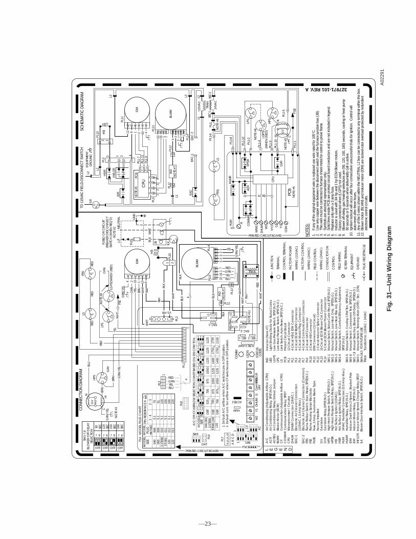
Fig
.31
—U
nit
Wir
ing
Dia
gra
mA
0229
1
L E G E N D
JUN
CTIO
N
TERM
INA
L
CO
NTR
OL
TERM
INA
L
FAC
TORY
PO
WER
WIR
ING
(115
VAC
)
FAC
TORY
CO
NTR
OL
WIR
ING
(24V
AC
)
FIEL
D C
ON
TRO
L
WIR
ING
(24V
AC
)
CO
ND
UC
TOR
ON
CO
NTR
OL
FIEL
D W
IRIN
G
SCRE
W T
ERM
INA
L
EQU
IPM
ENT
GRO
UN
D
PLUG
REC
EPTA
CLE
NO
TES:
327971-101 REV.A
1.If
any
of th
e or
igin
al e
quip
men
t wire
is re
plac
ed u
se w
ire ra
ted
for 1
05°C
.2.
Use
onl
y co
pper
wire
bet
wee
n th
e di
scon
nect
sw
itch
and
the
furn
ace
junc
tion
box
(JB)
.3.
This
wire
mus
t be
conn
ecte
d to
furn
ace
shee
t met
al fo
r con
trol t
o pr
ove
flam
e.4.
Sym
bols
are
ele
ctric
al re
pres
enta
tion
only
.5.
Solid
line
s in
side
PC
B ar
e pr
inte
d ci
rcui
t boa
rd c
ondu
ctor
s an
d ar
e no
t inc
lude
d in
lege
nd.
6.R
epla
ce o
nly
with
a 3
am
p fu
se.
7.In
duct
or is
use
d w
ith 3
/4 h
p an
d 1
hp E
CM
Blo
wer
mot
ors.
8.Fa
ctor
y co
nnec
ted
whe
n (L
GPS
) not
use
d.9.
Blow
er o
ff-de
lay,
gas
heat
ing
sele
ctio
ns a
re (9
0, 1
20, 1
50, 1
80) s
econ
ds, c
oolin
g or
hea
t pum
p 90
sec
onds
or 5
sec
onds
whe
n de
hum
idify
cal
l is
activ
e.10
.Ig
nitio
n lo
ckou
t will
occu
r afte
r fou
r con
secu
tive
unsu
cces
sful
tria
ls fo
r ign
ition
. C
ontro
l will
auto
-rese
t afte
r thr
ee h
ours
.11
.An
y of
the
5 w
ires
show
n w
ithin
the
NEU
TRAL
L2
box
can
be c
onne
cted
to a
ny te
rmin
al w
ithin
the
box.
12.
Blow
er m
otor
(BLW
M) a
nd In
duce
r mot
or (I
DM
) are
lock
ed-ro
tor o
verlo
ad p
rote
cted
by
redu
ndan
t el
ectro
nic
cont
rol c
ircui
ts.
A/C
A
ir C
ond
ition
ing
(Ad
just
ab
le A
irflo
w -C
FM)
AC
R
Air
Co
nditi
onin
g R
ela
y, S
PST
(N.O
.)A
CRD
J
Air
Con
diti
onin
g R
ela
y D
efea
t Jum
per
BLW
M
Blo
wer
Mo
tor (
ECM
)C
F
Con
tinuo
us F
an
(Ad
just
ab
le A
irflo
w -C
FM)
CO
MM
R C
omm
unic
atio
n Re
lay,
SPD
TC
PU
Mic
rop
roce
ssor
/ C
ircui
tryD
HU
M
DH
UM
Con
nect
ion
(24V
AC
)EA
C-1
E
lect
roni
c A
ir C
lea
ner C
onn
ect
ion
(
115V
AC
1.0
Am
p M
ax.
)EA
C-2
E
lect
roni
c A
ir C
lea
ner C
onn
ect
ion
(Com
mo
n)FR
S
Fla
me
Rollo
ut S
witc
h, M
an.
Res
et, S
PST(
N.C
.)FS
E
Fla
me-
Prov
ing
Sen
sor E
lect
rod
eFU
SE
Fus
e, 3
Am
p, A
uto
mot
ive
Bla
de
Typ
e,
F
act
ory
Inst
alle
dG
V
Ga
s Va
lve
GV
R
Ga
s Va
lve
Rela
y, D
PST
(N.O
.)H
PS
Hig
h-H
eat P
ress
ure
Switc
h, S
PST
(N.O
.)H
PSR
H
igh-
Hea
t Pre
ssur
e Sw
itch
Rela
y, S
PST
(N.C
.)H
SI
Ho
t Sur
fac
e Ig
nite
r (11
5VA
C)
HSI
R
Ho
t Sur
fac
e Ig
nite
r Rel
ay,
SPS
T (N
.O.)
HUM
2
4VA
C H
umid
ifier
Con
nect
ion
(0.5
Am
p M
ax.
)H
UMR
H
umid
ifier
Rel
ay,
SPS
T (N
.O.)
IDM
In
duc
er D
raft
Mo
tor, 2
-Sp
eed
, Sha
ded
Pol
eID
R
Ind
ucer
Mot
or R
ela
y, S
PST
(N.O
.)IH
I/LO
R I
nduc
er M
oto
r Sp
eed
Cha
nge
Rela
y, SP
DT
ILK
Bl
ower
Doo
r Int
erlo
ck S
witc
h, S
PST
(N.O
.)
IND
In
duc
tor (
No
te #
7)LE
D
Lig
ht E
mitt
ing
Dio
de
for S
tatu
s C
odes
LGPS
Lo
w G
as
Pre
ssur
e Sw
itch,
SPS
T (N
.O.)
LPS
Lo
w-H
eat P
ress
ure
Switc
h, S
PST
(N.O
.)LS
Lim
it Sw
itch,
Aut
o-Re
set,
SPST
(N
.C.)
PCB
Pr
inte
d C
ircui
t Bo
ard
PL1
12
-Circ
uit C
onne
cto
rPL
2
4-C
ircui
t HSI
& ID
M C
onne
ctor
PL3
4-
Circ
uit E
CM
BLW
M C
onne
ctor
PL4
4-
Circ
uit M
odel
Plu
g C
onn
ecto
rPL
7
4-C
ircui
t Com
mun
ica
tion
Co
nnec
tor
PL9
2-
Circ
uit O
AT
Co
nne
ctor
PL10
2-
Circ
uit H
SI C
onn
ect
orPL
11
IDM
Con
nect
or (
12-C
ircui
t)PL
12
1-C
ircui
t Ind
ucto
r Sp
lice
Co
nnec
tor
PL13
16
-Circ
uit E
CM
Blo
wer
Ctrl
. Con
nect
or
PL14
5-
Circ
uit E
CM
Blo
wer
Po
wer
Con
nect
orSW
1-1
M
anu
al S
witc
h, S
tatu
s C
ode
Reca
ll, SP
ST (N
.O.)
SW1-
2
Ma
nua
l Sw
itch,
Low
-He
at O
nly,
SPS
T(N
.O.)
SW1-
3
Ma
nua
l Sw
itch,
Low
-He
at R
ise A
dj.
SPST
(N.O
.)SW
1-4
M
anu
al S
witc
h, C
om
fort/
Effic
ienc
y A
dju
stm
ent,
SP
ST (
N.O
.)SW
1-5
M
anu
al S
witc
h, C
ool
ing
CFM
/To
n, S
PST
(N.O
.)SW
1-6
M
anu
al S
witc
h, C
om
po
nent
Test
, SPS
T (N
.O.)
SW1-
7,8
Ma
nua
l Sw
itche
s, B
low
er O
ff-D
ela
y, S
PST(
N.O
.)SW
4-1
M
anu
al S
witc
h, T
win
ning
Ma
in (O
FF) /
Sec
. (O
N)
SW4-
2&3
FO
R FU
TURE
USE
TRA
N
Tra
nsfo
rmer
, 115
VAC
/ 2
4VA
C
GV
M
CH
I
NO
TE #
3
BLU
BRN
HPS G
RN/Y
EL
FRS
LS
NO
TE #
8
GRY
RED
RED
RED
LPS
(WH
EN U
SED
)LG
PSBR
N
FSE
WH
T
PL3
1
4
HS
I
L1FUSE
D O
R C
IRC
UIT
BREA
KER
DIS
CO
NN
ECT
SWITC
H (W
HEN
REQ
’D)
NO
TE #
2
GN
D
NEU
TRAL
FU2 BL
K
ILK
PL10
JB
1 2
BLK
WH
T
PL1
TRAN
BLW
M
L1
EAC-1
PL12
IND
NO
TE #
7
PL12
4
HSI
PL2
VSBL
K
WH
TW
HT BL
U
SEC-2
CO
DE
SEC-1
HUM
FUSE3-AMP
W/W
1D
HU
MG
24Vom
CW
2Y
/Y2
RY
1S
TATU
S
LED
S
CO
MM
ACRDJ
PL8
PL9
OAT
SW4
PL7
AB
CD
CF
AC
SW1PL4
GRN
/YEL
1. D
efa
ult A
/C a
irflo
w w
hen
A/C
sw
itche
s a
re in
OFF
pos
itio
n2.
De
faul
t co
nt. f
an
airf
low
whe
n C
F sw
itche
s are
in O
FF p
ositi
on
A/C
OR
CF
AIR
FLO
W S
ELEC
TIO
N C
HA
RT B
ASE
D O
N 3
50 C
FM/T
ON
1H
SI
2
S
CH
EMAT
IC D
IAG
RAM
IDR
T
O 1
15VA
C F
IELD
-DIS
CO
NN
ECT
SWIT
CH
ILK
EQ
UIP
MEN
T G
RO
UN
D 1 23H
SIR
IHI/L
OR
PL2
L2
L2
FU1
NO
TE #
6
PL1-
8
R
PL1-
6
L2
PL1
0
4
CPU
NO
TE #
5PC
B
PL3
12
34
BLW
M
PL13
10 16 1 7
54
32 1
EAC
-1PL
14
PL12
IND
NO
TE #
7
PL12
L1
EAC
EAC
-2
TRAN
115V
AC
L1L2 SE
C2
SEC
1
24VA
C
PL1
-12
HPS
R
GV
LPS
NO
TE #
8
LGPS
(WH
EN U
SED
)H
PS HI
PL1-
2
PL1-
4
PL1-
3
PL1-
10
PL1-
5
W/W
1
CPU
GVR
DH
UM
W2
Y/Y2 G Y
1
CO
M
NO
TE #
3CM
PL1
-1FS
EN
OTE
#5
ACR
CO
MM
R
PCB
1
1
1
221
0017
5014
00
1225
1225
1225
1225
1050
1050
875
875
700
700
525
120
5T08
0,10
0D
EF.
DEF
.
DEF
.04
0,06
0,3.
5T08
0
SIZE
MO
DEL
1 2 3
OFF1 2 3
OFF1 2 3
OFF1 2 3
OFF1 2 3
OFF1 2 3
OFF1 2 3
OFF1 2 3
OFF
ORN
BLK
GRN
/YEL
516
17
10 BLUYELGRNRED
PL13
PL14
BLK
YEL
CO
NN
ECTI
ON
DIA
GR
AM
BLK W
HT
YEL14
32
BLUYELGRNRED
SW
1-7,
8BL
OW
ER O
FF D
ELAY
SELE
CTI
ON
90
SEC
120
SEC
150
SEC
180
SE
C
OFF OFF OFF OFF
7 8 7 8 7 8 7 8
11
2
1
1
ACRDJ
PRINTED CIRCIUT BOARD
PRINTED CIRCIUT BOARD
HU
MR
HU
M
RED
MO
DEL
MO
DEL
SIZE
PLU
GH
K70E
Z
PIN
RES
ISTA
NC
E K
1 - 4
2 - 3
040
060
3.5T
080
5T-0
8010
0
008
009
010
011
012
5.1
5.1
5.1
5.1
5.1
75 91 120
150
180
PL4
- MO
DEL
PLU
G C
HA
RT
120
013
5.1
220 2
700
875
1050
1225
1400
117
5017
50
IDM
GRN
/YEL
ORN
BRN
YEL
WH
TBL
K BLK
WH
T
FRS
LS
IDM
PL11
PL1-
9PL
1-11
PL1-
7
L2
NO
TE #
11
NEU
TRA
L - L
2
EAC-2
WH
TRE
D
4 2 10 1 12 642 10112 6
—23—
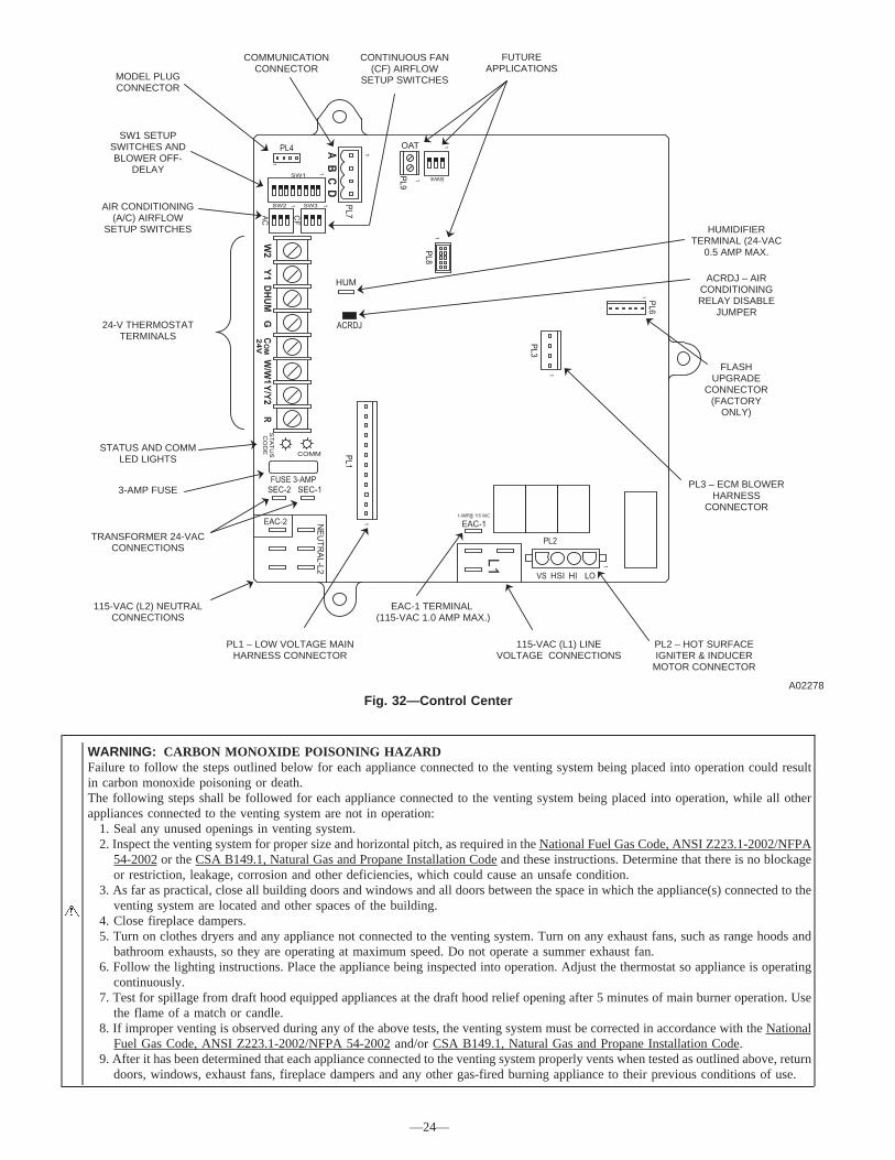
WARNING: CARBON MONOXIDE POISONING HAZARDFailure to follow the steps outlined below for each appliance connected to the venting system being placed into operation could resultin carbon monoxide poisoning or death.The following steps shall be followed for each appliance connected to the venting system being placed into operation, while all otherappliances connected to the venting system are not in operation:
1. Seal any unused openings in venting system.2. Inspect the venting system for proper size and horizontal pitch, as required in the National Fuel Gas Code, ANSI Z223.1-2002/NFPA
54-2002 or the CSA B149.1, Natural Gas and Propane Installation Code and these instructions. Determine that there is no blockageor restriction, leakage, corrosion and other deficiencies, which could cause an unsafe condition.
3. As far as practical, close all building doors and windows and all doors between the space in which the appliance(s) connected to theventing system are located and other spaces of the building.
4. Close fireplace dampers.5. Turn on clothes dryers and any appliance not connected to the venting system. Turn on any exhaust fans, such as range hoods and
bathroom exhausts, so they are operating at maximum speed. Do not operate a summer exhaust fan.6. Follow the lighting instructions. Place the appliance being inspected into operation. Adjust the thermostat so appliance is operating
continuously.7. Test for spillage from draft hood equipped appliances at the draft hood relief opening after 5 minutes of main burner operation. Use
the flame of a match or candle.8. If improper venting is observed during any of the above tests, the venting system must be corrected in accordance with the National
Fuel Gas Code, ANSI Z223.1-2002/NFPA 54-2002 and/or CSA B149.1, Natural Gas and Propane Installation Code.9. After it has been determined that each appliance connected to the venting system properly vents when tested as outlined above, return
doors, windows, exhaust fans, fireplace dampers and any other gas-fired burning appliance to their previous conditions of use.
Fig. 32—Control CenterA02278
FLASH UPGRADE
CONNECTOR (FACTORY
ONLY)
ACRDJ – AIR CONDITIONING RELAY DISABLE
JUMPER
HUMIDIFIER TERMINAL (24-VAC
0.5 AMP MAX.
CONTINUOUS FAN (CF) AIRFLOW
SETUP SWITCHES
COMMUNICATION CONNECTOR
AIR CONDITIONING (A/C) AIRFLOW
SETUP SWITCHES
MODEL PLUG CONNECTOR
SW1 SETUP SWITCHES AND BLOWER OFF-
DELAY
STATUS AND COMM LED LIGHTS
3-AMP FUSE
TRANSFORMER 24-VAC CONNECTIONS
PL3 – ECM BLOWER HARNESS
CONNECTOR
PL1 – LOW VOLTAGE MAIN HARNESS CONNECTOR
EAC-1 TERMINAL (115-VAC 1.0 AMP MAX.)
115-VAC (L1) LINE VOLTAGE CONNECTIONS
115-VAC (L2) NEUTRAL CONNECTIONS
PL2 – HOT SURFACE IGNITER & INDUCER
MOTOR CONNECTOR
24-V THERMOSTAT TERMINALS
FUTURE APPLICATIONS
—24—
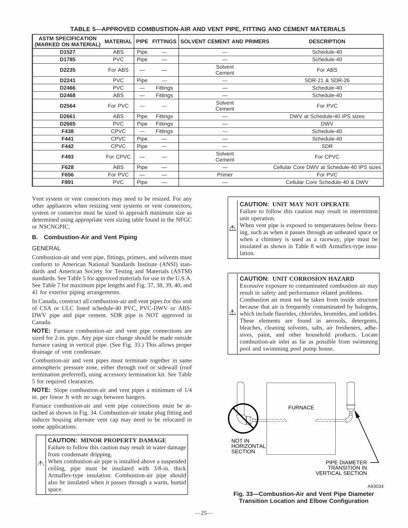
Vent system or vent connectors may need to be resized. For anyother appliances when resizing vent systems or vent connectors,system or connector must be sized to approach minimum size asdetermined using appropriate vent sizing table found in the NFGCor NSCNGPIC.
B. Combustion-Air and Vent Piping
GENERAL
Combustion-air and vent pipe, fittings, primers, and solvents mustconform to American National Standards Institute (ANSI) stan-dards and American Society for Testing and Materials (ASTM)standards. See Table 5 for approved materials for use in the U.S.A.See Table 7 for maximum pipe lengths and Fig. 37, 38, 39, 40, and41 for exterior piping arrangements.
In Canada, construct all combustion-air and vent pipes for this unitof CSA or ULC listed schedule-40 PVC, PVC-DWV or ABS-DWV pipe and pipe cement. SDR pipe is NOT approved inCanada.
NOTE: Furnace combustion-air and vent pipe connections aresized for 2-in. pipe. Any pipe size change should be made outsidefurnace casing in vertical pipe. (See Fig. 33.) This allows properdrainage of vent condensate.
Combustion-air and vent pipes must terminate together in sameatmospheric pressure zone, either through roof or sidewall (rooftermination preferred), using accessory termination kit. See Table5 for required clearances.
NOTE: Slope combustion-air and vent pipes a minimum of 1/4in. per linear ft with no sags between hangers.
Furnace combustion-air and vent pipe connections must be at-tached as shown in Fig. 34. Combustion-air intake plug fitting andinducer housing alternate vent cap may need to be relocated insome applications.
CAUTION: MINOR PROPERTY DAMAGEFailure to follow this caution may result in water damagefrom condensate dripping.When combustion-air pipe is installed above a suspendedceiling, pipe must be insulated with 3/8-in. thickArmaflex-type insulation. Combustion-air pipe shouldalso be insulated when it passes through a warm, humidspace.
CAUTION: UNIT MAY NOT OPERATEFailure to follow this caution may result in intermittentunit operation.When vent pipe is exposed to temperatures below freez-ing, such as when it passes through an unheated space orwhen a chimney is used as a raceway, pipe must beinsulated as shown in Table 8 with Armaflex-type insu-lation.
CAUTION: UNIT CORROSION HAZARDExcessive exposure to contaminated combustion air mayresult in safety and performance related problems.Combustion air must not be taken from inside structurebecause that air is frequently contaminated by halogens,which include fluorides, chlorides, bromides, and iodides.These elements are found in aerosols, detergents,bleaches, cleaning solvents, salts, air fresheners, adhe-sives, paint, and other household products. Locatecombustion-air inlet as far as possible from swimmingpool and swimming pool pump house.
TABLE 5—APPROVED COMBUSTION-AIR AND VENT PIPE, FITTING AND CEMENT MATERIALS
ASTM SPECIFICATION(MARKED ON MATERIAL) MATERIAL PIPE FITTINGS SOLVENT CEMENT AND PRIMERS DESCRIPTION
D1527 ABS Pipe — — Schedule-40D1785 PVC Pipe — — Schedule-40
D2235 For ABS — — SolventCement For ABS
D2241 PVC Pipe — — SDR-21 & SDR-26D2466 PVC — Fittings — Schedule-40D2468 ABS — Fittings — Schedule-40
D2564 For PVC — — SolventCement For PVC
D2661 ABS Pipe Fittings — DWV at Schedule-40 IPS sizesD2665 PVC Pipe Fittings — DWVF438 CPVC — Fittings — Schedule-40F441 CPVC Pipe — — Schedule-40F442 CPVC Pipe — — SDR
F493 For CPVC — — SolventCement For CPVC
F628 ABS Pipe — — Cellular Core DWV at Schedule-40 IPS sizesF656 For PVC — — Primer For PVCF891 PVC Pipe — — Cellular Core Schedule-40 & DWV
Fig. 33—Combustion-Air and Vent Pipe DiameterTransition Location and Elbow Configuration
A93034
FURNACE
PIPE DIAMETERTRANSITION IN
VERTICAL SECTION
NOT INHORIZONTALSECTION
—25—

Table 6—Direct Vent Termnination ClearanceA05009
A
X
B
V
V
V
V
X
X
AIR SUPPLY INLETV VENT TERMINAL AREA WHERE TERMINAL IS NOT PERMITED
A
B
B
B
B
C
D
E
F
J
I
L
H
K
G
25--24--65--2
O
YY
X
Item Clearance Description Canadian Installation (1) U.S. Installation (2)
A Clearance above grade, veranda, porch, deck, balcony, oranticipated snow level
12˝ (30cm) # 12˝ (30 cm)
B Clearance to a window or door that may be opened 12 ˝(30 cm) for appliances > 10,000 Btuh (3 kW)and ≤ 100,000 Btuh(30 kW), 36˝(91 cm) for appliances > 100,000 Btuh (30 kW)
9˝ (23 cm)for appliances > 10,000 Btuh (3 kW)and ≤ 50,000 Btuh (15kW), 12 ˝(30 cm) for appliances > 50,000 Btuh (15 kW)
C Clearance to a permanently closed window * *
D Vertical clearance to a ventilated soffit located above theterminal within a horizontal distance of 2 ´(61cm) from thecenterline of the terminal
* *
E Clearance to an unventilated soffit * *
F Clearance to an outside corner * *
G Clearance to an inside corner * *
H Clearance to each side of the centerline extended aboveelectrical meter or gas service regulator assembly
3´ (91 cm) within 15 ´(4.5 m) above the meter/regulatorassembly
3´ (91 cm) within 15´(4.5 m) above the meter/regulatorassembly
I Clearance to service regulator vent outlet 3´ (91 cm) *
J Clearance to non--mechanical air supply inlet to building orthe combustion air inlet to any other appliance
9˝ (23 cm)for appliances > 10,000 Btuh (3 kW) and ≤ 100,000 Btuh (30kW) and ≤50,000 Btuh (15 kW), 12˝(30 cm) for appliances > 50,000 Btuh (15 kW)
9˝(23 cm) for appliances > 10,000 Btuh (3 kW)and ≤ 50,000 Btuh (15kW), 12 ˝(30 cm) for appliances > 50,000 Btuh (15 kW)
K Clearance to a mechanical air supply inlet 6´ (1.83 m) 3´ (91 cm) above if within 10 ´(3m)horizontally
L Clearance under a veranda, porch, deck, or balcony 12˝ (30 cm) + *
M Clearance to each side of the centerline extended above orbelow vent terminal of the furnace to a dryer or water heatervent, or other appliance’s direct vent intake or exhaust.
12˝ (30 cm) 12˝ (30 cm)
O Clearance from a plumbing vent stack 3´ (91 cm) 3´ (91 cm)
(1.) In accordance with the current CSA B149.1, Natural Gas and Propane Installation Code
(2.) In accordance with the current ANSI Z223.1/NFPA 54, National Fuel Gas Code
# 18 ˝ (46 cm) above roof surface
+ Permitted only if veranda, porch, deck, or balcony is fully open on a minimum of two sides beneath the floor.
* For clearances not specified in ANSI Z223.1/NFPA 54 or CSA B149.1, clearances shall be in accordance with local installation codes and the requirements of the gas supplier and the
Notes:1. The vent for this appliance shall not terminate
a. Over public walkways; orb. Near soffit vents or crawl space vents or other areas where condensate or vapor could create a nusaince or hazard or property damage; orc. Where condensate vapor could cause damage or could be detrimental to the operation of regulators, relief valves, or other equipment.
2. When locating vent terminations, consideration must be given to prevailing winds, location, and other conditions which may cause recirculation of the combustion products of adjacent vents.Recirculation can cause poor combustion, inlet condensate problems, and accelerated corrosion of the heat exchangers.
FIXED
CLOSED
OPERABLE
OPERABLEFIXED
CLOSED
N Clearance to the vent terminal of a dryer vent, water heatervent, or other appliances direct vent intake or exhaust.
3´ (91 cm) 3´ (91 cm)
N
V
M
manufacturer’s installation instructions
3. Avoid venting under a deck or large overhang. Recirculation could occur and cause performance or system problems.
P Clearance above paved sidewalk or paveddriveway located on public property 7´ (2.13m)** *
** A vent shall not terminate above a sidewalk or paved driveway that is located between two single family dwellings and serves both dwellings.
B
P
—26—
→
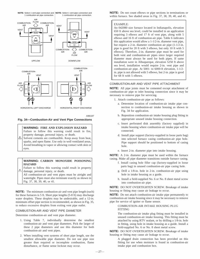
WARNING: FIRE AND EXPLOSION HAZARDFailure to follow this warning could result in fire,property damage, personal injury, or death.Solvent cements are combustible. Keep away from heat,sparks, and open flame. Use only in well ventilated areas.Avoid breathing in vapor or allowing contact with skin oreyes.
WARNING: CARBON MONOXIDE POISONINGHAZARDFailure to follow this warning could result in propertydamage, personal injury, or death.All combustion-air and vent pipes must be airtight andwatertight. Pipes must also terminate exactly as shown inFig. 37, 38, 39, 40, or 41.
NOTE: The minimum combustion-air and vent pipe length (each)for these furnaces is 5 ft. Short pipe lengths (5-8 ft) may dischargewater droplets. These droplets may be undesirable, and a 12-in.minimum offset pipe section is recommended, as shown in Fig. 35,to reduce excessive droplets from exiting vent pipe outlet.
COMBUSTION-AIR AND VENT PIPE DIAMETER
Determine combustion-air and vent pipe diameter.
1. Using Table 7, individually determine the smallestcombustion-air and vent pipe diameters. Pick the larger ofthese 2 pipe diameters and use this diameter for bothcombustion-air and vent pipes.
2. When installing vent systems of short pipe length, use thesmallest allowable pipe diameter. Do not use pipe sizegreater than required or incomplete combustion, flamedisturbance, or flame sense lockout may occur.
NOTE: Do not count elbows or pipe sections in terminations orwithin furnace. See shaded areas in Fig. 37, 38, 39, 40, and 41.
EXAMPLE:An 042080 size furnace located in Indianapolis, elevation650 ft above sea level, could be installed in an applicationrequiring 3 elbows and 17 ft of vent pipe, along with 5elbows and 16 ft of combustion-air pipe. Table 6 indicatesthis application would allow a 1-1/2-in. diameter vent pipe,but require a 2-in. diameter combustion air pipe (1-1/2-in.pipe is good for 20 ft with 3 elbows, but only 10 ft with 5elbows). Therefore, 2-in. diameter pipe must be used forboth vent and combustion-air pipes since larger requireddiameter must always be used for both pipes. If sameinstallation were in Albuquerque, elevation 5250 ft abovesea level, installation would require 2-in. vent pipe andcombustion-air pipe. At 5001- to 6000-ft elevation, 1-1/2-in. pipe is not allowed with 5 elbows, but 2-in. pipe is goodfor 68 ft with 5 elbows.
COMBUSTION-AIR AND VENT PIPE ATTACHMENT
NOTE: All pipe joints must be cemented except attachment ofcombustion-air pipe to inlet housing connection since it may benecessary to remove pipe for servicing.
1. Attach combustion-air pipe as follows:a. Determine location of combustion-air intake pipe con-
nection to combustion-air intake housing as shown inFig. 34 for application.
b. Reposition combustion-air intake housing plug fitting inappropriate unused intake housing connection.
c. Insert perforated disk assembly (factory supplied) inintake housing where combustion-air intake pipe will beconnected.
d. Install pipe support (factory-supplied in loose parts bag)into selected furnace casing combustion-air pipe hole.Pipe support should be positioned to bottom of casinghole.
e. Insert 2-in. diameter pipe into intake housing.
NOTE: A 2-in. diameter pipe must be used within the furnacecasing. Make all pipe diameter transitions outside furnace casing.
f. Install casing hole filler cap (factory-supplied in looseparts bag) in unused combustion-air pipe casing hole.
g. Drill a 1/8-in. hole in 2-in. combustion-air pipe usinghole in intake housing as a guide.
h. Install a field-supplied No. 6 or No. 8 sheet metal screwinto combustion-air pipe.
NOTE: DO NOT OVERTIGHTEN SCREW. Breakage of intakehousing or fitting may cause air leakage to occur.NOTE: Do not attach combustion-air intake pipe permanently tocombustion-air intake housing since it may be necessary to removepipe for service of igniter or flame sensor.
COMBUSTION-AIR INTAKE HOUSING PLUGFITTING
The combustion-air intake plug fitting must be installed inunused combustion-air intake housing. This fitting must beattached by using RTV sealant, or by drilling a 1/8-in. holein fitting, using hole in intake housing as a guide. Install afield-supplied No. 6 or No. 8 sheet metal screw.
NOTE: DO NOT OVERTIGHTEN SCREW. Breakage of intakehousing or fitting may cause air leakage to occur.
A plugged drain connection has been provided on thisfitting for use when moisture is found in combustion-airintake pipe and combustion box.
Fig. 34—Combustion-Air and Vent Pipe ConnectionsA96187
COMBUSTION-AIR
COMBUSTION-AIR
AIRFLOW
VENT
VENT
VENT
AIRFLOW
AIRFLOW
AIRFLOW
UPFLOW DOWNFLOW
HORIZONTAL-LEFT DISCHARGE HORIZONTAL-RIGHT DISCHARGE
Select 1 vent pipe connection and1 combustion-air pipe connection.
COMBUSTION-AIR
COMBUSTION-AIR
COMBUSTION-AIR
COMBUSTION-AIR
VENT
VENT
VENT
NOTE: Select 1 vent pipe connection and1 combustion-air pipe connection.
NOTE:
—27—

NOTE: Moisture in combustion-air intake may be result ofimproper termination. Ensure combustion-air intake pipe termina-tion is similar to that shown in Fig. 37, 38, 39, 40, or 41 so it willnot be susceptible to areas where light snow or other sources ofmoisture could be pulled in.
If use of this drain connection is desired, drill out fitting’stap plug with a 3/16-in. drill and connect a field-supplied3/8-in. tube. This tube should be routed to open condensatedrain for furnace and A/C (if used), and should be trapped.(See Fig. 36.)
2. Attach vent pipe as follows:a. Determine location of vent pipe connection to inducer
housing as shown in Fig. 34 for application.
b. Reposition elastomeric (rubber) inducer housing outletcap and clamp to appropriate unused inducer housingconnection. Tighten clamp.
CAUTION: UNIT DAMAGE HAZARDFailure to follow this caution may result in unit compo-nent damage.Inducer housing outlet cap must be installed and fullyseated against inducer housing. Clamp must be tightenedto prevent any condensate leakage.
c. Install pipe support (factory-supplied in loose parts bag)into selected furnace casing vent pipe hole. Pipe supportshould be positioned to bottom of casing hole.
CAUTION: UNIT DAMAGE HAZARDFailure to follow this caution may result in unit compo-nent damage.Vent pipe must be installed and fully seated againstinducer housing internal stop. Clamp must be tightened toprevent any condensate leakage.
NOTE: A 2-in. diameter pipe must be used within the furnacecasing. Make all pipe diameter transitions outside furnace casing.
d. Be certain that mating surfaces of inducer housingconnection, elastomeric coupling, and 2-in. diametervent pipe are clean and dry. Assemble the elastomeric(rubber) vent coupling (with 2 loose clamps) ontoinducer housing connection. Insert the 2-in. diametervent pipe through the elastomeric (rubber) coupling andfully into inducer housing connection until it bottoms onthe internal stop. Tighten both clamps to secure the pipeto inducer housing. Tighten the clamp screws to 15in.-lb. of torque.
e. Install casing hole filler cap (factory-supplied in looseparts bag) in unused combustion-air pipe casing hole.
3. Working from furnace to outside, cut pipe to requiredlength(s).
4. Deburr inside and outside of pipe.5. Chamfer outside edge of pipe for better distribution of
primer and cement.
Fig. 35—Short Vent (5 to 8 Ft) SystemA96230
HORIZONTAL TO ROOF HORIZONTAL TO SIDEWALL
VERTICAL TO SIDEWALLVERTICAL TO ROOF
VENT PIPE
COMBUSTION-AIR PIPE COMBUSTION-AIR PIPE
VENT PIPE
COMBUSTION-AIR PIPEVENT PIPE
COMBUSTION-AIR PIPE
VENT PIPE
12″ MIN
12″ MIN
12″ MIN
12″ MIN
NOTE: A 12 In. minimum offset pipe section is recommended with short (5 to 8 ft) vent systems. This recommendation is to reduce excessive condensate droplets from exiting the vent pipe.
—28—

TABLE 7—MAXIMUM ALLOWABLE PIPE LENGTH (FT)
ALTITUDE UNITSIZE
TERMINATIONTYPE
PIPE DIAMETER(IN.)*
NUMBER OF 90° ELBOWS1 2 3 4 5 6
0 to 2000
042040 2 Pipe or 2-In.Concentric
1-1/2 50 45 40 35 30 252 70 70 70 70 70 70
042060 2 Pipe or 2-In.Concentric
1-1/2 50 45 40 35 30 252 70 70 70 70 70 70
042080060080
2 Pipe or 2-In.Concentric
1-1/2 30 25 20 15 10 52 70 70 70 70 70 70
060100 2 Pipe or 2-In.Concentric
2 45 40 35 30 25 202-1/2 70 70 70 70 70 70
060120 2 Pipe or 3-In.Concentric
2-1/2 10 NA NA NA NA NA3 35 30 15 NA NA NA3† 70 70 70 70 70 70
Altitude UnitSize
TerminationType
Pipe Diameter(In.)*
Number of 90° Elbows1 2 3 4 5 6
2001 to 3000
042040 2 Pipe or 2-In.Concentric
1-1/2 45 40 35 30 25 202 70 70 70 70 70 70
042060 2 Pipe or 2-In.Concentric
1-1/2 45 40 35 30 25 202 70 70 70 70 70 70
042080060080
2 Pipe or 2-In.Concentric
1-1/2 26 21 16 11 6 NA2 70 70 70 70 70 70
060100 2 Pipe or 2-In.Concentric
2 40 35 30 25 20 152-1/2 70 70 70 70 70 70
060120 2 Pipe or 3-In.Concentric
3 31 26 12 NA NA NA3† 63 62 62 61 61 61
Altitude UnitSize
TerminationType
Pipe Diameter(In.)*
Number of 90° Elbows1 2 3 4 5 6
3001 to 4000
042040 2 Pipe or 2-In.Concentric
1-1/2 42 37 32 27 22 172 70 70 70 70 70 70
042060 2 Pipe or 2-In.Concentric
1-1/2 42 37 32 27 22 172 70 70 70 70 70 70
042080060080
2 Pipe or 2-In.Concentric
1-1/2 25 20 15 10 5 NA2 70 70 70 70 70 70
060100 2 Pipe or 2-In.Concentric
2 38 33 28 23 18 132-1/2 70 70 70 70 70 70
060120 2 Pipe or 3-In.Concentric
3 29 24 10 NA NA NA3† 59 59 58 57 57 56
Altitude UnitSize
TerminationType
Pipe Diameter(In.)*
Number of 90° Elbows1 2 3 4 5 6
4001 to 5000‡
042040 2 Pipe or 2-In.Concentric
1-1/2 40 35 30 25 20 152 70 70 70 70 70 70
042060 2 Pipe or 2-In.Concentric
1-1/2 40 35 30 25 20 152 70 70 70 70 70 70
042080060080
2 Pipe or 2-In.Concentric
1-1/2 23 18 13 8 NA NA2 70 70 70 70 70 68
060100 2 Pipe or 2-In.Concentric
2 36 31 26 21 16 112-1/2 70 70 70 70 70 70
060120 2 Pipe or 3-In.Concentric 3† 56 55 54 53 52 52
Altitude UnitSize
TerminationType
Pipe Diameter(In.)*
Number of 90° Elbows1 2 3 4 5 6
5001 to 6000‡
042040 2 Pipe or 2-In.Concentric
1-1/2 37 32 27 22 17 122 70 70 70 70 70 70
042060 2 Pipe or 2-In.Concentric
1-1/2 37 32 27 22 17 122 70 70 70 70 70 70
042080060080
2 Pipe or 2-In.Concentric
1-1/2 22 17 12 7 NA NA2 70 70 70 70 68 63
060100 2 Pipe or 2-In.Concentric
2 33 28 23 18 13 82-1/2 70 70 70 70 70 70
060120 2 Pipe or 3-In.Concentric 3† 53 52 50 49 48 47
See notes on next page.
—29—
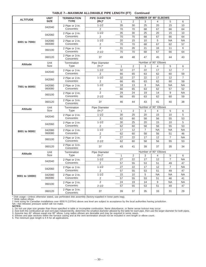
TABLE 7—MAXIMUM ALLOWABLE PIPE LENGTH (FT) Continued
ALTITUDE UNITSIZE
TERMINATIONTYPE
PIPE DIAMETER(IN.)*
NUMBER OF 90° ELBOWS1 2 3 4 5 6
6001 to 7000‡
042040 2 Pipe or 2-In.Concentric
1-1/2 35 30 25 20 15 102 70 70 68 67 66 64
042060 2 Pipe or 2-In.Concentric
1-1/2 35 30 25 20 15 102 70 70 68 67 66 64
042080060080
2 Pipe or 2-In.Concentric
1-1/2 20 15 10 5 NA NA2 70 70 68 67 62 57
060100 2 Pipe or 2-In.Concentric
2 31 26 21 16 11 62-1/2 70 70 68 67 66 64
060120 2 Pipe or 3-In.Concentric 3† 49 48 47 45 44 43
Altitude UnitSize
TerminationType
Pipe Diameter(In.)*
Number of 90° Elbows1 2 3 4 5 6
7001 to 8000‡
042040 2 Pipe or 2-In.Concentric
1-1/2 32 27 22 17 12 72 66 65 63 62 60 59
042060 2 Pipe or 2-In.Concentric
1-1/2 32 27 22 17 12 72 66 65 63 62 60 59
042080060080
2 Pipe or 2-In.Concentric
1-1/2 18 13 8 NA NA NA2 66 65 63 62 57 52
060100 2 Pipe or 2-In.Concentric
2 29 24 19 14 9 NA2-1/2 66 65 63 62 60 59
060120 2 Pipe or 3-In.Concentric 3† 46 44 43 41 40 38
Altitude UnitSize
TerminationType
Pipe Diameter(In.)*
Number of 90° Elbows1 2 3 4 5 6
8001 to 9000‡
042040 2 Pipe or 2-In.Concentric
1-1/2 30 25 20 15 10 52 62 60 58 56 55 53
042060 2 Pipe or 2-In.Concentric
1-1/2 30 25 20 15 10 52 62 60 58 56 55 53
042080060080
2 Pipe or 2-In.Concentric
1-1/2 17 12 7 NA NA NA2 62 60 58 56 51 46
060100 2 Pipe or 2-In.Concentric
2 27 22 17 12 7 NA2-1/2 62 60 58 56 55 53
060120 2 Pipe or 3-In.Concentric 3† 43 41 39 37 35 34
Altitude UnitSize
TerminationType
Pipe Diameter(In.)*
Number of 90° Elbows1 2 3 4 5 6
9001 to 10000‡
042040 2 Pipe or 2-In.Concentric
1-1/2 27 22 17 12 7 NA2 57 55 53 51 49 47
042060 2 Pipe or 2-In.Concentric
1-1/2 27 22 17 12 7 NA2 57 55 53 51 49 47
042080060080
2 Pipe or 2-In.Concentric
1-1/2 15 10 5 NA NA NA2 57 55 53 51 46 41
060100 2 Pipe or 2-In.Concentric
2 24 19 14 9 NA NA2-1/2 57 55 53 51 49 47
060120 2 Pipe or 3-In.Concentric 3† 39 37 35 33 31 29
* Disk usage—Unless otherwise stated, use perforated disk assembly (factory-supplied in loose parts bag).† Wide radius elbow.‡ Vent sizing for Canadian installations over 4500 ft (1370m) above sea level are subject to acceptance by the local authorities having jurisdiction.NA—Not Allowed; pressure switch will not make.NOTES:1. Do not use pipe size greater than those specified in table or incomplete combustion, flame disturbance, or flame sense lockout may occur.2. Size both the combustion-air and vent pipe independently, determine the smallest diameter allowed by the table for each pipe, then use the larger diameter for both pipes.3. Assume two 45° elbows equal one 90° elbow. Long radius elbows are desirable and may be required in some cases.4. Elbows and pipe sections within the furnace casing and at the vent termination should not be included in vent length or elbow count.5. The minimum pipe length is 5 ft for all applications.
—30—

6. Clean and dry all surfaces to be joined.
7. Check dry fit of pipe and mark insertion depth on pipe.
NOTE: It is recommended that all pipes be cut, prepared, andpreassembled before permanently cementing any joint.
8. After pipes have been cut and preassembled, apply gener-ous layer of cement primer to pipe fitting socket and end ofpipe to insertion mark. Quickly apply approved cement toend of pipe and fitting socket (over primer). Apply cementin a light, uniform coat on inside of socket to preventbuildup of excess cement. Apply second coat.
9. While cement is still wet, twist pipe into socket with 1/4turn. Be sure pipe is fully inserted into fitting socket.
10. Wipe excess cement from joint. A continuous bead ofcement will be visible around perimeter of a properly madejoint.
11. Handle pipe joints carefully until cement sets.
12. Support combustion-air and vent piping a minimum ofevery 5 ft (3 ft for SDR-21 or -26 PVC) using perforatedmetal hanging strap.
13. Slope combustion-air and vent pipes downward towardfurnace a minimum of 1/4 in. per linear ft with no sagsbetween hangers.
14. Use appropriate methods to seal openings where vent andcombustion-air pipes pass through roof or sidewall.
C. Concentric Vent and Combustion-AirTermination Kit Installation
NOTE: If these instructions differ from those packaged withtermination kit, follow kit instructions.
Combustion-air and vent pipes must terminate outside structure. Afactory accessory termination kit must be installed in 1 of theinstallations shown in Fig. 37, 38, 39, 40, or 41. Four terminationkits are available.
See Table 6 for additional termination information.
1. The 2-in. termination bracket kit is for 1-in., 1-1/2 in., and2-in. diameter 2-pipe termination systems.
2. The 3-in. termination bracket kit is for 2-1/2 in. and 3-in.diameter 2-pipe termination systems.
3. The 2-in. concentric vent/air termination kit is for 1-in.,1-1/2 in., 2-in., and 2-1/2 in. diameter pipe systems whensingle penetration of wall or roof is desired.
4. The 3-in. concentric vent/air termination kit is for 2-1/2 in.and 3-in. diameter pipe systems when single penetration ofwall or roof is desired.
NOTE: Shaded parts in Fig. 37, 38, 39, 40, and 41 are consideredto be terminations. These components should NOT be countedwhen determining pipe diameter. Roof termination is preferred
since it is less susceptible to damage, has reduced chances to takein contaminants, and has less visible vent vapors. (See Fig. 37 or38.) Sidewall termination may require sealing or shielding ofbuilding surfaces with a corrosive resistance material due tocorrosive combustion products of vent system.
EXTENDED EXPOSED SIDEWALL PIPES
Sidewall combustion-air and vent pipe terminations may beextended beyond area shown in Fig. 40 or 41 in outside ambient byinsulating pipes as indicated in Table 8.
1. Determine combustion-air and vent pipe diameters, asstated above, using total pipe length and number of elbows.
2. Using winter design temperature (used in load calculations),find appropriate temperature for your application and fur-nace model.
3. Determine required insulation thickness for exposed pipelengths.
NOTE: Pipe length (ft) specified for maximum pipe lengthslocated in unconditioned spaces cannot exceed total allowable pipelength as specified in Table 7.
TWO-PIPE TERMINATION KIT
1. Determine location for termination.
Consideration of the following should be made whendetermining an appropriate location for termination kit.
a. Comply with all clearance requirements as stated inTable 6.
b. Termination kit should be positioned where vent vaporswill not damage plants/shrubs or air conditioning equip-ment.
c. Termination kit should be positioned so it will not beaffected by wind eddy (such as inside building corners)or accumulation of airborne leaves or light snow, orallow recirculation of flue gases.
d. Termination kit should be positioned where it will not bedamaged by or subjected to foreign objects, such asstones, balls, etc.
e. Termination kit should be positioned where vent vaporsare not objectionable.
2. Cut 2 holes, 1 for each pipe, of appropriate size for pipe sizebeing used.
3. Loosely install elbow in bracket and place assembly oncombustion-air pipe.
Roof terminations—Loosely install pipe coupling on prop-erly cut vent pipe. Coupling must be positioned so bracketwill mount as shown in Fig. 37.
For applications using combustion-air pipe option indicatedby dashed lines in Fig. 37, install 90° street elbow into 90°elbow, making U-fitting. A 180° U-fitting may be used.
Sidewall terminations—Install bracket as shown in Fig. 40or 41.
For applications using vent pipe option indicated by dashedlines in Fig. 40, rotate vent elbow 90° from position shownin Fig. 40.
4. Disassemble loose pipe fittings. Clean and cement usingsame procedures as used for system piping.
5. Check required dimensions as shown in Fig. 37, 40, or 41.
CONCENTRIC VENT/AIR TERMINATION KIT
1. Determine location for termination.
Consideration of the following should be made whendetermining an appropriate location for termination kit.
Fig. 36—Air Intake Housing Plug Fitting DrainA93035
COMBUSTION –AIR PIPE
BURNERBOX
COMBUSTION – AIRINTAKE HOUSING
3/8" ID TUBE
TRAP
TO OPENDRAIN
3/16"DRILL
4″MIN
—31—

Fig. 40—Sidewall Termination of 12 in. or MoreA87225
MAINTAIN 12 IN.CLEARANCEABOVE HIGHESTANTICIPATED SNOWLEVEL OR GRADE,WHICHEVER ISGREATER.
90°
VENT
12 IN. SEPARATIONBETWEEN BOTTOM OFCOMBUSTION AIR ANDBOTTOM OF VENT
BRACKET
COMBUSTION-AIR
12″ MINIMUM
OVERHANG OR ROOF
Fig. 38—Concentric Vent and Combustion-Air RoofTermination (Preferred)
A93054
COMBUSTIONAIR
MAINTAIN 12 IN.(18 IN. FOR CANADA)MINIMUM CLEARANCEABOVE HIGHESTANTICIPATED SNOWLEVEL. MAXIMUM OF24 IN. ABOVE ROOF.
VENT
Fig. 41—Sidewall Termination of Less than 12 in.A87226
MAINTAIN 12 IN.CLEARANCEABOVE HIGHESTANTICIPATED SNOWLEVEL OR GRADE,WHICHEVER ISGREATER.
90°
VENT
12 IN. SEPARATIONBETWEEN BOTTOM OFCOMBUSTION AIR ANDBOTTOM OF VENT
BRACKET
COUPLING
12″ MINIMUM
OVERHANG OR ROOF
COMBUSTION-AIR(ELBOW PARALLELTO WALL)
Fig. 39—Concentric Vent and Combustion-Air SideTermination
A93055
MAINTAIN 12 IN.CLEARANCEABOVE HIGHESTANTICIPATED SNOWLEVEL OR GRADE,WHICHEVER ISGREATER.
COMBUSTION-AIR
VENT
1″ MAXIMUM
12″ MINIMUM
OVERHANG OR ROOF
Fig. 37—Roof Termination (Preferred)A87224
18″ MAXIMUM
COMBUSTIONAIR
COUPLING
ROOF
VENT
BRACKET
VERTICAL SEPARATIONBETWEEN COMBUSTION
AIR AND VENT8 3/4″ FOR 3″ KIT6 3/4″ FOR 2″ KIT
MAINTAIN 12 IN. MINIMUMCLEARANCE ABOVE HIGHEST
ANTICIPATED SNOW LEVEL.MAXIMUM OF 24 IN. ABOVE ROOF.
—32—

Fig. 45—Sidewall Termination of 12 in. or Less(Dimension "A" is Touching or 2-In.
Maximum Separation)
A96129
A
COMBUSTION AIR
COMBUSTION AIR
VENT
Fig. 43—Concentric Vent and Combustion-Air RoofTermination (Dimension "A" is Touching or
2-In. Maximum Separation)
A93056
COMBUSTIONAIR
VENTVENT
A
Fig. 46—Sidewall Termination of More Than 12 in.(Dimension "A" is Touching or 2-In.
Maximum Separation)
A96130
COMBUSTION AIRCOMBUSTION AIR
VENT
A
Fig. 44—Concentric Vent and Combustion-Air SideTermination (Dimension "A" is Touching or
2-In. Maximum Separation)
A93057
COMBUSTION AIR
VENT
A
VENT
1″ MAXIMUM(TYP)
Fig. 42—Rooftop Termination (Dimension "A" is Touching or 2-In. Maximum Separation)A96128
A
—33—
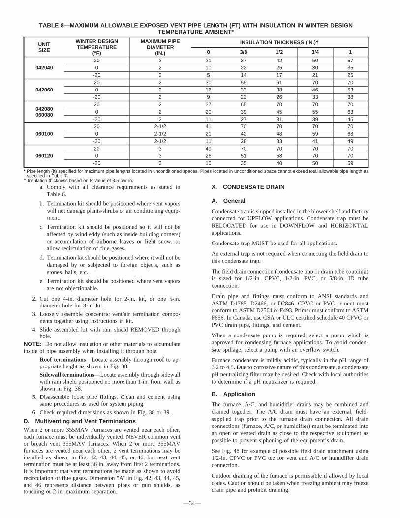
a. Comply with all clearance requirements as stated inTable 6.
b. Termination kit should be positioned where vent vaporswill not damage plants/shrubs or air conditioning equip-ment.
c. Termination kit should be positioned so it will not beaffected by wind eddy (such as inside building corners)or accumulation of airborne leaves or light snow, orallow recirculation of flue gases.
d. Termination kit should be positioned where it will not bedamaged by or subjected to foreign objects, such asstones, balls, etc.
e. Termination kit should be positioned where vent vaporsare not objectionable.
2. Cut one 4-in. diameter hole for 2-in. kit, or one 5-in.diameter hole for 3-in. kit.
3. Loosely assemble concentric vent/air termination compo-nents together using instructions in kit.
4. Slide assembled kit with rain shield REMOVED throughhole.
NOTE: Do not allow insulation or other materials to accumulateinside of pipe assembly when installing it through hole.
Roof terminations—Locate assembly through roof to ap-propriate height as shown in Fig. 38.
Sidewall terminations—Locate assembly through sidewallwith rain shield positioned no more than 1-in. from wall asshown in Fig. 38.
5. Disassemble loose pipe fittings. Clean and cement usingsame procedures as used for system piping.
6. Check required dimensions as shown in Fig. 38 or 39.
D. Multiventing and Vent Terminations
When 2 or more 355MAV Furnaces are vented near each other,each furnace must be individually vented. NEVER common ventor breach vent 355MAV furnaces. When 2 or more 355MAVfurnaces are vented near each other, 2 vent terminations may beinstalled as shown in Fig. 42, 43, 44, 45, or 46, but next venttermination must be at least 36 in. away from first 2 terminations.It is important that vent terminations be made as shown to avoidrecirculation of flue gases. Dimension "A" in Fig. 42, 43, 44, 45,and 46 represents distance between pipes or rain shields, astouching or 2-in. maximum separation.
X. CONDENSATE DRAIN
A. General
Condensate trap is shipped installed in the blower shelf and factoryconnected for UPFLOW applications. Condensate trap must beRELOCATED for use in DOWNFLOW and HORIZONTALapplications.
Condensate trap MUST be used for all applications.
An external trap is not required when connecting the field drain tothis condensate trap.
The field drain connection (condensate trap or drain tube coupling)is sized for 1/2-in. CPVC, 1/2-in. PVC, or 5/8-in. ID tubeconnection.
Drain pipe and fittings must conform to ANSI standards andASTM D1785, D2466, or D2846. CPVC or PVC cement mustconform to ASTM D2564 or F493. Primer must conform to ASTMF656. In Canada, use CSA or ULC certified schedule 40 CPVC orPVC drain pipe, fittings, and cement.
When a condensate pump is required, select a pump which isapproved for condensing furnace applications. To avoid conden-sate spillage, select a pump with an overflow switch.
Furnace condensate is mildly acidic, typically in the pH range of3.2 to 4.5. Due to corrosive nature of this condensate, a condensatepH neutralizing filter may be desired. Check with local authoritiesto determine if a pH neutralizer is required.
B. Application
The furnace, A/C, and humidifier drains may be combined anddrained together. The A/C drain must have an external, field-supplied trap prior to the furnace drain connection. All drainconnections (furnace, A/C, or humidifier) must be terminated intoan open or vented drain as close to the respective equipment aspossible to prevent siphoning of the equipment’s drain.
See Fig. 48 for example of possible field drain attachment using1/2-in. CPVC or PVC tee for vent and A/C or humidifier drainconnection.
Outdoor draining of the furnace is permissible if allowed by localcodes. Caution should be taken when freezing ambient may freezedrain pipe and prohibit draining.
TABLE 8—MAXIMUM ALLOWABLE EXPOSED VENT PIPE LENGTH (FT) WITH INSULATION IN WINTER DESIGNTEMPERATURE AMBIENT*
UNITSIZE
WINTER DESIGNTEMPERATURE
(°F)
MAXIMUM PIPEDIAMETER
(IN.)
INSULATION THICKNESS (IN.)†
0 3/8 1/2 3/4 1
04204020 2 21 37 42 50 570 2 10 22 25 30 35
-20 2 5 14 17 21 25
04206020 2 30 55 61 70 700 2 16 33 38 46 53
-20 2 9 23 26 33 38
042080060080
20 2 37 65 70 70 700 2 20 39 45 55 63
-20 2 11 27 31 39 45
06010020 2-1/2 41 70 70 70 700 2-1/2 21 42 48 59 68
-20 2-1/2 11 28 33 41 49
06012020 3 49 70 70 70 700 3 26 51 58 70 70
-20 3 15 35 40 50 59
* Pipe length (ft) specified for maximum pipe lengths located in unconditioned spaces. Pipes located in unconditioned space cannot exceed total allowable pipe length asspecified in Table 7.
† Insulation thickness based on R value of 3.5 per in.
—34—

WARNING: PERSONAL INJURY ANDPROPERTY DAMAGE HAZARDFailure to follow this warning could result in propertydamage and personal injury or death.Caution should be taken to prevent draining whereslippery conditions may cause personal injuries. Exces-sive condensate draining may cause saturated soil condi-tions which could result in damage to plants.
CAUTION: UNIT MAY NOT OPERATEFailure to follow this caution may result in intermittentunit operation.Unit must not be installed, operated, and then turned andleft off in an unoccupied structure during cold weatherwhen temperature drops to 32°F or below unless draintrap and drain line have adequate freeze protection. SeeService and Maintenance Instructions for winterizingprocedure. (See Fig. 47.)
C. Condensate Drain Protection
Freezing condensate left in condensate trap and drain line maycause cracks, and possible water damage may occur. If freezeprotection is required, use condensate freeze protection accessoryor equivalent 3 to 6 watt per ft at 120v and 40°F self-regulating,shielded, and waterproof heat tape. See Installation Instructionssupplied with accessory or heat tape manufacturer’s recommenda-tions.
1. Fold heat tape in half and wrap on itself 3 times.
2. Locate heat tape between sides of condensate trap back.(See Fig. 49.)
3. Use wire ties to secure heat tape in place. Wire ties can bepositioned in notches of condensate trap sides. (See Fig.49.)
4. Wrap field drain pipe with remaining heat tape, approxi-mately 1 wrap per ft.
5. When using field-supplied heat tape, follow heat tapemanufacturer’s instructions for all other installation guide-lines.
START-UP, ADJUSTMENTS AND SAFETY CHECKI. GENERAL
1. Furnace must have a 115-v power supply properly con-nected and grounded.
NOTE: Proper polarity must be maintained for 115-v wiring. Ifpolarity is incorrect, control status indicator light flashes rapidlyand furnace does not operate.
2. Thermostat wire connections at terminals R, W/W1, G, andY/Y2 must be made at 24-v terminal block on furnacecontrol.
3. Natural gas service pressure must not exceed 0.5 psig(14-in. wc), but must be no less than 0.16 psig (4.5-in. wc).
4. Blower access panel must be in place to complete 115-velectrical circuit to furnace.
Fig. 47—Freeze ProtectionA93058
32°F MINIMUM INSTALLEDAMBIENT OR FREEZEPROTECTION REQUIRED
Fig. 48—Example of Field Drain AttachmentA94054
OPEN STANDPIPE FOR
A/C ORHUMIDIFIER
DRAIN
TEE
TO OPENDRAIN
Fig. 49—Condensate Trap Heat TapeA93036
CONDENSATE TRAP
WIRE TIE(S)
HEAT TAPE(3 WRAPS MINIMUM)
—35—

CAUTION: UNIT MAY NOT OPERATEFailure to follow this caution may result in intermittentunit operation or performance satisfaction.These furnaces are equipped with a manual reset limitswitch in burner box. This switch opens and shuts offpower to the gas valve if an overheat condition (flamerollout) occurs in burner enclosure. Correct inadequatecombustion-air supply or improper venting conditionbefore resetting switch. DO NOT jumper this switch.
Before operating furnace, check flame rollout manual reset switchfor continuity. If necessary, press button to reset switch.
II. SELECT SETUP SWITCH POSITIONS
A. Air Conditioning (A/C) Setup Switches
The air conditioning setup switches are used to match furnaceairflow to cooling unit used.
To set the desired cooling airflow:
1. Remove main furnace door and blower access door.
2. Locate A/C setup switches on frunace control. (See Fig.32.)
3. Determine air conditioning tonnage used.
4. Use Fig. 50 or wiring schematic to determine proper setupposition of A/C switches. (See Fig. 31 and 51.)
NOTE: Excessive airflow caused by improper A/C switch setupmay cause condensate blow off in cooling mode.
5. Replace main furnace door and blower access door.
NOTE: EAC-1 terminal is energized whenever blower operates.HUM terminal is only energized when blower is energized inheating.
B. Continuous Fan (CF) Setup Switches
The CF setup switches are used to select desired airflow whenthermostat is in continuous fan mode or to select low-coolingairflow for two-speed cooling units. This setup feature allowscontinuous fan airflow or low-cooling airflow to be adjusted. Toset desired continuous fan airflow or low-cooling airflow:
1. Remove main furnace door and blower access door.
2. Locate CF setup switches on furnace control. (See Fig. 32.)
3. Determine desired continuous fan airflow or low-coolingairflow.
4. Use Fig. 58 or wiring schematic to determine proper setupposition of CF switches. (See Fig. 31 and 51.)
5. Replace main furnace door and blower access panel.
C. Setup Switches (SW1)
The furnace control has 8 setup switches that may be set to meetthe application requirements. Position these setup switches for theappropriate requirement.
1. Remove main furnace door and blower access panel.
2. Locate setup switches on furnace control. (See Fig. 32.)
3. See Table 9 for setup switch description. (See Fig. 31 and51.)
A02335
Fig. 50—A/C or CF Airflow Selection ChartBased on 350CFM/Ton
AIR CONDITIONING AIRFLOW 040,060 & 042080 MODEL
060080 & 100MODEL 120 MODELTONS (12,000 BTU/HR) (CFM)
1-1/2 525 X
X
2 700 X X X
2-1/2 875 X X X
3 1050 X X X
3-1/2 1225 X X X
4 1400 X X
5 1750 X
6 2100 X
X-INDICATES AN ALLOWABLE SELECTION.
A/C OR CF AIRFLOW SELECTION CHARTBASED ON 350 CFM/TON
MODELSIZE
040, 060,042080 DEF 5252 700 875 10501 1225 1225 1225
060080, 100 DEF 700 875 1050 1225 1400 17501 1750
120 DEF 700 8752 1050 1225 1400 17501 2100
1.DEFAULT A/C AIRFLOW WHEN A/C SWITCHES ARE IN OFF POSITION
2.DEFAULT CONT. FAN AIRFLOW WHEN CF SWITCHES ARE IN OFF POSITION
2
—36—

4. Replace main furnace door and blower access panel.NOTE: If a bypass humidifier is used, setup switch SW1-3 (LowHEAT Rise Adjust) should be in ON position. This compensatesfor the increased temperature in return air resulting from bypass.NOTE: If modulating dampers are used, blower motor automati-cally compensates for modulating dampers.
III. PRIME CONDENSATE TRAP WITH WATER
CAUTION: UNIT MAY NOT OPERATEFailure to follow this caution may result in intermittentunit operation or performance satisfaction.Condensate trap must be PRIMED or proper drainingmay not occur. The condensate trap has 2 internalchambers which can ONLY be primed by pouring waterinto the inducer drain side of condensate trap.
1. Remove upper inducer housing drain connection cap. (SeeFig. 52.)
2. Connect field-supplied 1/2-in. ID tube to upper inducerhousing drain connection.
3. Insert field-supplied funnel into tube.
4. Pour 1 quart of water into funnel/tube. Water should runthrough inducer housing, overfill condensate trap, and flowinto open field drain. (See Fig. 53.)
5. Remove funnel and tube from inducer housing and replacedrain connection cap and clamp.
IV. PURGE GAS LINES
If not previously done, purge the lines after all connections havebeen made and check for leaks.
WARNING: FIRE AND EXPLOSION HAZARDFailure to follow this warning could result in a fire,explosion, personal injury, or death.Never purge a gas line into a combustion chamber. Nevertest for gas leaks with an open flame. Use a commerciallyavailable soap solution made specifically for the detectionof leaks to check all connections.
V. SEQUENCE OF OPERATION
CAUTION: UNIT MAY NOT OPERATEFailure to follow this caution may result in intermittentunit operation.Furnace control must be grounded for proper operation,or control will lock out. Control is grounded throughgreen/yellow wire routed to gas valve and burner boxscrew.
Using schematic diagram, follow sequence of operation throughdifferent modes. (See Fig. 31.) Read and follow wiring diagramcarefully.NOTE: If a power interruption occurs during a call for heat(W/W1 or W/W1-and-W2), the control will start a 90-secondblower-only ON period two seconds after power is restored, if thethermostat is still calling for gas heating. The amber LED light willflash code 12 during the 90-second period, after which the LEDwill be ON continuous, as long as no faults are detected. After the90-second period, the furnace will respond to the thermostatnormally.The blower door must be installed for power to be conductedthrough the blower door interlock switch ILK to the furnacecontrol CPU, transformer TRAN, inducer motor IDM, blowermotor BLWM, hot-surface igniter HSI, and gas valve GV.A. Single-Stage Thermostat and Two-StageHeating (Adaptive Mode)
See Fig. 28 or 61 for thermostat connectionsFig. 51—Example of Setup Switch in OFF PositionA04001
TABLE 9—FURNACE SETUP SWITCH DESCRIPTIONSETUP
SWITCH NO.SWITCHNAME
NORMALPOSITION
DESCRIPTIONOF USE
SW1-1 Status Code Recovery OFF Turn ON to retrieve up to 7 stored status codes for troubleshootingassistance when R thermostat lead is disconnected.
SW1-2 Adaptive Heat Mode OFF
Allows 2-stage operation with a single stage thermostat.Turn ON when using 2 stage thermostat to allow Low Heat opera-tion when R to W/W1 closes and High Heat operation when R to
W/W1 and W2 close.
SW1-3 Low HeatRise Adjust OFF
Turn ON to increase Low Heat airflow by 18 percent. This compen-sates for increased return air temperature caused with bypass hu-
midifier.
SW1-4 Comfort/Efficiency Adjustment ONTurn ON to decrease Low Heat airflow by 7 percent and High Heatairflow 8 percent for maximum comfort. On 040 unit will decreaseLow-Heat Airflow 11 percent and High-Heat Airflow 10 percent.
SW1-5 CFM per ton adjust OFF Turn ON for 400 CFM per ton. Turn OFF for 350 CFM per ton.
SW1-6 Component Self-Test OFFTurn ON to initiate Component Self-Test for troubleshooting assis-
tance when R thermostat lead is disconnected.Turn OFF when Self-Test is completed.
SW1-7 Blower OFF delay ON or OFF Control blower Off Delay time. Used in conjunction with SW1-8. SeeTable 10.
SW1-8 Blower OFF delay ON or OFF Control blower Off Delay time. Used in conjunction with SW1-7. SeeTable 10.
TABLE 10—BLOWER OFF DELAY SETUP SWITCHPOSITION
DESIRED HEATINGMODE BLOWER
OFF DELAY (SEC)
SETUP SWITCH (SW1-7 AND SW1-8) POSITION
SW1-7 SW1-8
90 OFF OFF120 ON OFF150 OFF ON180 ON ON
—37—

NOTE: Low-heat-only switch, SW1-2, selects either the low-heat-only operation mode when ON, (see item 2. below) oradaptive heating mode when OFF, in response to a call for heat.(See Fig. 32.) When the W2 thermostat terminal is energized, itwill always cause high-heat operation when the R to W circuit isclosed, regardless of the setting of the low-heat only switch.
This furnace can operate as a two-stage furnace with a single-stagethermostat because furnace control CPU includes a programmedadaptive sequence of controlled operation, which selects low-heator high-heat operation. This selection is based upon the storedhistory of the length of previous gas heating periods of thesingle-stage thermostat.
The furnace will start up in either low- or high-heat. If the furnacestarts up in low-heat, the furnace control CPU determines thelow-heat on time (from 0 to 16 minutes) which is permitted beforeswitching to high-heat.If power is interrupted, the stored history is erased. When thishappens, the control CPU will initially select low-heat for up to 16minutes and then switch to high-heat, as long as the thermostatcontinues to call for heat. Subsequent selection is based on storedhistory of thermostat cycle times.The wall thermostat ″calls for heat″, closing the R to W circuit.The furnace control CPU performs a self-check, verifies thelow-heat and high-heat pressure switch contacts LPS and HPS areopen.
1. Inducer Prepurge Period-The furnace control CPU turnson inducer motor IDM and slowly increases the inducermotor speed. When the low-heat pressure switch LPScloses, inducer motor RPM is noted by the furnace controlCPU, and a 25-sec prepurge period begins. The RPM isused to evaluate vent system resistance. This evaluation isthen used to determine the required RPM necessary tooperate the inducer motor during the low-heat prepurgeperiod and low-heat mode.
NOTE: The heat cycle can start in either high-or low-heat. If ahigh-heat cycle is initiated, the furnace control CPU will de-energize the high-heat pressure switch relay HPSR to close the NCcontact and continues to increase the inducer motor speed after thelow-heat pressure switch LPS closes. When the high-heat pressureswitch closes, inducer motor RPM is noted by the furnace controlCPU before the 25-sec prepurge period begins. The RPM is usedto evaluate vent system resistance. This evaluation is then used todetermine the required RPM necessary to operate the inducermotor in high-heat mode.
2. Igniter Warm-Up-At end of the prepurge period, the HotSurface Igniter HSI is energized for a 17-sec igniterwarm-up period.
3. Trial-For-Ignition Sequence-When the igniter warm-upperiod is completed the main gas valve relay contacts GVRclose to energize the gas valve solenoid GV, the gas valveopens. The gas valve GV permits gas flow to the burnerswhere it is ignited by the Hot Surface Igniter HSI. Fiveseconds after the GVR closes, a 2-second flame periodbegins. The HSI igniter will remain energized until theflame is sensed or until the 2-second flame proving periodbegins.
If the furnace control CPU selects high-heat operation, thehigh-heat gas valve solenoid GV-HI is also energized.
4. Flame-Proving-When burner flame is proved at the flame-proving sensor electrode FSE, the furnace control CPUbegins the blower-ON delay period and continues to holdthe gas valve GV-M open. If the burner flame is not provedwithin two seconds, the control CPU will close the gasvalve GV-M, and the furnace control CPU will repeat theignition sequence for up to three more Trials-For-Ignitionbefore going to Ignition-Lockout. Lockout will be resetautomatically after three hours, by momentarily interrupting
Fig. 52—Inducer Housing Drain TubeA99118
Fig. 53—Filling Condensate TrapA99119
—38—

115 vac power to the furnace, or by interrupting 24 vacpower at SEC1 or SEC2 to the furnace control CPU (not atW/W1, G, R, etc.).
If flame is proved when flame should not be present, thefurnace control CPU will lock out of Gas-Heating mode andoperate the inducer motor IDM on high speed until flame isno longer proved.
5. Inducer Speed Change-If the cycle starts in low-heat, thefurnace control CPU reduces the inducer speed slightly afterflame sense. If cycle starts in high-heat, the furnace controlCPU increases the inducer speed 15 seconds after flamesense. The reduction in speed in low-heat is to optimizecombustion for maximum efficiency.
6. Blower-On delay-If the burner flame is proven, theblower-ON delay for low-heat and high-heat are as follows:
Low-heat-60 seconds after the gas valve GV-M is opened,the BLWM is turned ON at low-heat airflow.
High-heat-35 seconds after gas valve GV-M is opened, theBLWM is turned ON at high-heat airflow.
Simultaneously, the humidifier terminal HUM and elec-tronic air cleaner terminal EAC-1 are energized and remainenergized throughout the heating cycle.
7. Switching From Low- To High- Heat- If the furnacecontrol CPU switches from low-heat to high-heat, thefurnace control CPU will de-energize the the high-heatpressure switch relay HPSR to close the NC contact andslowly increase the inducer motor speed until the high-heatpressure switch HPS closes. When the high-heat pressureswitch HPS closes, the high-heat gas valve solenoid GV-HIis energized and the inducer motor RPM is noted by thefurnace control CPU. The RPM is used to evaluate ventsystem resistance. This evaluation is then used to determinethe required RPM necessary to operate the inducer motor inhigh-heat mode. The blower motor BLWM will transitionto high-heat airflow five seconds after the furnace controlCPU switches from low-heat to high-heat.
8. Switching From High- To Low- Heat-The furnace controlCPU will not switch from high-heat to low-heat while thethermostat R-to-W circuit is closed when using a single-stage thermostat.
9. Blower-Off delay- When the thermostat is satisfied, the Rto W circuit is opened, de-energizing the gas valve GV-M,stopping gas flow to the burners, and de-energizing thehumidifier terminal HUM. The inducer motor IDM willremain energized for a 15-second post-purge period. Theblower motor BLWM and air cleaner terminal EAC-1 willremain energized at low-heat airflow or transition to low-heat airflow for 90, 120, 150, or 180 seconds (depending onselection at blower-OFF delay switches). The furnacecontrol CPU is factory-set for a 120-second blower-OFFdelay.
B. Two-Stage Thermostat and Two-Stage Heating
See Fig. 60 for thermostat connectionsNOTE: In this mode, the low-heat only switch SW1-2 must beON to select the low-heat only operation mode in response toclosing the thermostat R-to-W1 circuit. Closing the thermostatR-to-W1-and-W2 circuits always causes high-heat operation, re-gardless of the setting of the low-heat-only switch.The wall thermostat ″calls for heat″, closing the R to W1 circuit forlow-heat or closing the R to W1-and-W2 circuits for high-heat.The furnace control performs a self-check and verifies the low-heat and high-heat pressure switch contacts LPS and HPS areopen.The start-up and shutdown functions and delays described in item1. above apply to 2-stage heating mode as well, except forswitching from low- to high-heat and vice versa.
1. Switching From Low- To High- Heat-If the thermostat Rto W1 circuit is closed and the R to W2 circuit closes, thefurnace control CPU will de-energize the high-heat pressureswitch relay HPSR to close the NC contact and slowlyincrease the inducer motor speed until the high-heat pres-sure switch HPS closes. When the high-heat pressure switchcloses, the high-heat gas valve solenoid GV-HI is energizedand the inducer motor RPM is noted by the furnace controlCPU. The RPM is used to evaluate vent system resistance.This evaluation is then used to determine the required RPMnecessary to operate the inducer motor in high-heat mode.The blower motor BLWM will transition to high-heatairflow five seconds after the R to W2 circuit closes.
2. Switching From High- To Low- Heat- If the thermostat Rto W2 circuit opens, and the R to W1 circuit remains closed,the furnace control CPU will energize the high-heat pres-sure switch relay HPSR to open the NC contact and slowlydecrease the inducer motor speed to the required low-heatRPM. When the high-heat pressure switch HPS opens, thehigh-heat gas valve solenoid GV-HI is de-energized. Whenthe inducer motor IDM reduces pressure sufficiently, thehigh-heat pressure switch HPS will open. The gas valvesolenoid GV-M will remain energized as long as thelow-heat pressure switch LPS remains closed. The blowermotor BLWM will transition to low-heat airflow fiveseconds after the R to W2 circuit opens.
C. Cooling Mode
The thermostat “calls for cooling”
1. Single-Speed Cooling(See Fig. 28 for thermostat connections.)
The thermostat closes R-to-G-and-Y circuits. The R-to-Ycircuit starts the outdoor unit, and R-to-G-and-Y/Y2 circuitsstart the furnace blower motor BLWM on cooling airflow.Cooling airflow is based on the A/C selection shown in Fig.50.
The electronic air cleaner terminal EAC-1 is energized with115-v when blower motor BLWM is operating.
When the thermostat is satisfied, the R-to-G-and-Y circuitsare opened. The outdoor unit will stop, and furnace blowermotor BLWM will continue operating at cooling airflow foran additional 90 sec. Jumper Y/Y2 to DHUM to reduce thecooling off-delay to 5 seconds. (See Fig. 32.)
2. Single-Stage Thermostat and Two-Speed Cooling(Adaptive Mode)(See Fig. 61 for thermostat connections.)
This furnace can operate a two-speed cooling unit with asingle-stage thermostat because the furnace control CPUincludes a programmed adaptive sequence of controlledoperation, which selects low-cooling or high-cooling opera-tion. This selection is based upon the stored history of thelength of previous cooling period of the single-stage ther-mostat.
NOTE: The air conditioning relay disable jumper ACRDJ mustbe connected to enable the adaptive cooling mode in response to acall for cooling. (See Fig. 32.) When in place the furnace controlCPU can turn on the air conditioning relay ACR to energize theY/Y2 terminal and switch the outdoor unit to high-cooling.
The furnace control CPU can start up the cooling unit ineither low- or high-cooling. If starting up in low-cooling,the furnace control CPU determines the low-cooling on-time (from 0 to 20 minutes) which is permitted beforeswitching to high-cooling.
If the power is interrupted, the stored history is erased andthe furnace control CPU will select low-cooling for up to 20minutes and then energize the air conditioning relay ACR to
—39—

energize the Y/Y2 terminal and switch the outdoor unit tohigh-cooling, as long as the thermostat continues to call forcooling. Subsequent selection is based on stored history ofthe thermostat cycle times.
The wall thermostat ″calls for cooling″, closing the R toG-and-Y circuits. The R to Y1 circuit starts the outdoor uniton low-cooling speed, and the R to G-and-Y1 circuits startsthe furnace blower motor BLWM at low-cooling airflowwhich is the true on-board CF selection as shown in Fig. 50.
If the furnace control CPU switches from low-cooling tohigh-cooling, the furnace control CPU will energize the airconditioning relay ACR. When the air conditioning relayACR is energized the R to Y1-and-Y2 circuits switch theoutdoor unit to high-cooling speed, and the R to G-and-Y1-and-Y/Y2 circuits transition the furnace blower motorBLWM to high-cooling airflow. High-cooling airflow isbased on the A/C selection shown in Fig. 50.
NOTE: When transitioning from low-cooling to high-cooling theoutdoor unit compressor will shut down for 1 minute while thefurnace blower motor BLWM transitions to run at high-coolingairflow.
The electronic air cleaner terminal EAC-1 is energized with115 vac whenever the blower motor BLWM is operating.
When the thermostat is satisfied, the R to G-and-Y circuitare opened. The outdoor unit stops, and the furnace blowerBLWM and electronic air cleaner terminal EAC-1 willremain energized for an additional 90 seconds. Jumper Y1to DHUM to reduce the cooling off-delay to 5 seconds. (SeeFig. 32.)
3. Two-Stage Thermostat and Two-Speed Cooling
(See Fig. 60 for thermostat connections)NOTE: The air conditioning relay disable jumper ACRDJ mustbe disconnected to allow thermostat control of the outdoor unitstaging. (See Fig. 32.)
The thermostat closes the R to G and-Y1 circuits forlow-cooling or closes the R to G and-Y1-and-Y2 circuits forhigh-cooling. The R to Y1 circuit starts the outdoor unit onlow-cooling speed, and the R to G-and-Y1 circuit starts thefurnace blower motor BLWM on low-cooling airflowwhich is the true on-board CF selection as shown in Fig. 50.The R to Y1-and-Y2 circuits start the outdoor unit onhigh-cooling speed, and the R to G-and-Y/Y2 circuits startthe furnace blower motor BLWM at high-cooling ariflow.High-cooling airflow is based on the A/C selection shownin Fig. 50.
The electronic air cleaner terminal EAC-1 is energized with115 vac whenever the blower motor BLWM is operating.
When the thermostat is satisfied, the R to G-and-Y1 or R toG-and-Y1-and-Y2 circuits are opened. The outdoor unitstops, and the furnace blower BLWM and electronic aircleaner terminal EAC-1 will remain energized for anadditional 90 seconds. Jumper Y1 to DHUM to reduce thecooling off-delay to 5 seconds. (See Fig. 32.)
D. Thermidistat Mode
See Fig. 54-57 for Thermidistat connections.The dehumidification output, DHUM on the Thermidistat shouldbe connected to the furnace control thermostat terminal DHUM.When there is a dehumidify demand, the DHUM input is activated,which means 24 vac signal is removed from the DHUM inputterminal. In other words, the DHUM input logic is reversed. TheDHUM input is turned ON when no dehumidify demand exists.Once 24 vac is detected by the furnace control on the DHUMinput, the furnace control operates in Thermidistat mode. If theDHUM input is low for more than 48 hours, the furnace controlreverts back to non-Thermidistat mode.
The cooling operation described in item 3. above applies tooperation with a Thermidistat. The exceptions are listed below:
a. Low cooling-When the R to G-and-Y1 circuit is closedand there is a demand for dehumidification, the furnaceblower motor BLWM will drop the blower airflow to86% of low-cooling airflow which is the true on-boardCF selection as shown in Fig. 50.
b. High cooling-When the R to G-and Y/Y2 circuit isclosed and there is a demand for dehumidification, thefurnace blower motor BLWM will drop the blowerairflow to 86% of high-cooling airflow. High-coolingairflow is based on the A/C selection shown in Fig. 50.
c. Cooling off-delay-When the ″call for cooling″ is satis-fied and there is a demand for dehumidification, thecooling blower-off delay is decreased from 90 seconds to5 seconds.
E. Super-Dehumidify Mode
Super-Dehumidify mode can only be entered if the furnace controlis in Thermidistat mode and there is a demand for dehumidifica-tion. The cooling operation described in item 3. above also appliesto operation with a Thermidistat. The exceptions are listed below:
a. Low cooling-When the R to Y1 circuit is closed, R to Gcircuit is open, and there is a demand for dehumidifica-tion, the furnace blower motor BLWM will drop theblower airflow to 65% of low-cooling airflow for amaximum of 10 minutes each cooling cycle or until theR to G circuit closes or the demand for dehumidificationis satisfied. Low-cooling airflow is the true on-board CFselection as shown in Fig. 50.
b. High cooling-When the R to Y/Y2 cicuit is closed, R toG circuit is open, and there is a demand for dehumidi-fiation, the furnace blower motor BLWM will drop theblower to 65% of high-cooling airflow for a maximumof 10 minutes each cooling cycle or until the R to Gcircuit closes or the demand for dehumidification issatisfied. High-cooling airflow is based on the A/Cselection shown in Fig. 50.
c. Cooling off-delay-When the ″call for cooling″ is satis-fied and there is a demand for dehumidification, thecooling blower-off delay is decreased from 90 seconds to5 seconds.
F. Continuous Blower Mode
When the R to G circuit is closed by the thermostat, the blowermotor BLWM will operate at continuous-blower airflow. Continu-ous blower airflow selection is initially based on the CF selectionshown in Fig. 50. Factory default is shown in Fig. 58. TerminalEAC-1 is energized as long as the blower motor BLWM isenergized.
During a call for heat, the blower BLWM will transition the blowermotor BLWM to continuous blower airflow, low-heat airflow, orthe midrange airflow, whichever is lowest. The blower motorBLWM will remain ON until the main burners ignite then shutOFF and remain OFF for the blower-ON delay (60 seconds inlow-heat and 35 seconds in high-heat) allowing the furnace heatexchangers to heat more quickly, then restarts at the end of theblower-ON delay period at low-heat or high-heat airflow respec-tively.
The blower motor BLWM will revert to continuous-blower airflowafter the heating cycle is completed. In high-heat, the furnacecontrol CPU will drop the blower motor BLWM to low-heatairflow during the selected blower-OFF delay period beforetransitioning to continuous-blower airflow.
—40—

When the thermostat ″calls for high-cooling″, the blower motorBLWM will operate at high-cooling airflow. When the thermostatis satisfied, the blower motor BLWM will operate an additional 90seconds at high-cooling airflow before transitioning back tocontinuous-blower airflow.
When the R to G circuit is opened, the blower motor BLWM willcontinue operating for an additional 5 seconds, if no other functionrequires blower motor BLWM operation.
Continuous Blower Speed Selection from ThermostatTo select different continuous-blower speeds from the roomthermostat, momentarily turn off the FAN switch or push-button on the room thermostat for 1-3 seconds after theblower motor BLWM is operating. The furnace controlCPU will shift the continuous-blower airflow from thefactory setting to the next highest CF selection airflow asshown in Fig. 50. Momentarily turning off the FAN switchagain at the thermostat will shift the continuous-blowerairflow up one more increment. If you repeat this procedureenough, you will eventually shift the continuous-blowerairflow to the lowest CF selection as shown in Fig. 50. Theselection can be changed as many times as desired and isstored in the memory to be automatically used following apower interruption.
G. Heat Pump
See Fig. 56-59 for thermostat connections.When installed with a heat pump, the furnace control automaticallychanges the timing sequence to avoid long blower off times duringdemand defrost cycles. Whenever W/W1 is energized along withY1 or Y/Y2, the furnace control CPU will transition to or bring onthe blower motor BLWM at cooling airflow, low-heat airflow, orthe midrange airflow, whichever is the lowest. The blower motorBLWM will remain on until the main burners ignite, then shut OFFand remain OFF for 25 seconds before coming back on at heatingairflow. When the W/W1 input signal disappears, the furnacecontrol begins a normal inducer post-purge period while changingthe blower airflow. If Y/Y2 input is still energized, the furnacecontrol CPU will transition the blower motor BLWM airflow tocooling airflow. If Y/Y2 input signal disappears and the Y1 inputis still energized, the furnace control CPU will transition theblower motor BLWM to low-cooling airflow. If both the Y1 andY/Y2 signals disappear at the same time, the blower motor BLWMwill remain on at low-heat airflow for the selected blower-OFFdelay period. At the end of the blower-OFF delay, the blowermotor BLWM will shut OFF unless G is still energized, in whichcase the blower motor BLWM will operate at continuous blowerairflow.
H. Component Test
The furnace features a component test system to help diagnose asystem problem in the case of a component failure. To initiate thecomponent test procedure, ensure that there are no thermostatinputs to the control and all time delays have expired. Turn onsetup switch SW1-6. (See Fig. 32.)NOTE: The component test feature will not operate if the controlis receiving any thermostat signals or until all time delays haveexpired.The component test sequence is as follows:
a. The furnace control CPU turns the inducer motor IDMON at medium speed and keeps it ON through step c.
b. After waiting 15 seconds, the furnace control CPU turnsthe hot surface igniter ON for 15 seconds, then OFF.
c. The furnace control CPU then turns the blower motorBLWM ON at midrange airflow for 15 seconds, thenOFF.
d. After shutting the blower motor BLWM OFF, thefurnace control CPU shuts the inducer motor IDM OFF.
NOTE: The EAC terminals are energized when the blower isoperating.
After the component test is completed, 1 or more status codes (11,25, 41, or 42) will flash. See Service Label on blower access panelor Service/Status Code Instructions for explanation of status codes.
NOTE: To repeat component test, turn setup switch SW1-6 toOFF and then back ON.
VI. ADJUSTMENTS
A. Set Gas Input Rate
Furnace gas input rate on rating plate is for installations at altitudesup to 2000 ft.
In the U.S.A., the input rating for altitudes above 2000 ft must bereduced by 2 percent for each 1000 ft above sea level.
In Canada, the input rating must be derated by 5 percent foraltitudes of 2000 ft to 4500 ft above sea level.
Adjust manifold pressure to obtain input rate.
Furnace input rate must be within ±2 percent of input on furnacerating plate.
1. Determine natural gas orifice size and manifold pressure forcorrect input.
a. Obtain average heat value (at installed altitude) fromlocal gas supplier.
b. Obtain average specific gravity from local gas supplier.
c. Verify furnace model. Table 11 can only be used formodel 355MAV Furnaces.
d. Find installation altitude in Table 11.
NOTE: For Canada altitudes of 2000 to 4500 ft, use U.S.A.altitudes of 2001 to 3000 ft in Table 11.
e. Find closest natural gas heat value and specific gravity inTable 11.
f. Follow heat value and specific gravity lines to point ofintersection to find orifice size and low- and high-heatmanifold pressure settings for proper operation.
EXAMPLE: (0—2000 ft altitude)Heating value = 1050 Btu/cu ftSpecific gravity = 0.62Therefore: Orifice No. 45
Manifold pressure: 3.8-in. wc for high heat1.6-in. wc for low heat
* Furnace is shipped with No. 45 orifices. In this example,all main burner orifices are the correct size and do not needto be changed to obtain proper input rate.
g. Check and verify burner orifice size in furnace. NEVERASSUME ORIFICE SIZE; ALWAYS CHECK ANDVERIFY.
2. Adjust manifold pressure to obtain input rate.
a. Remove burner enclosure front.
NOTE: Manifold pressure MUST always be measured with theburner box cover REMOVED.
b. Remove regulator seal caps that conceal adjustmentscrews for low- and high-heat gas valve regulators. (SeeFig. 62.)
c. Turn setup switch SW1-2 on control center to ONposition. (See Fig. 32.) This keeps furnace locked inlow-heat operation.
d. Jumper R and W/W1 thermostat connections on furnacecontrol to start furnace.
—41—

A00275
Fig. 54—Two-Stage Furnace with Single-SpeedAir Conditioner
Fig. 55—Two-Stage Furnace with Two-SpeedAir Conditioner
A00276
A00277
Fig. 56—Two-Stage Furnace with Single-Speed Heat Pump(Dual Fuel)
A00278
Fig. 57—Two-Stage Furnace with Two-Speed Heat Pump(Dual Fuel)
—42—

A00279
Fig. 58—Dual Fuel Thermostat with Two-StageFurnace and Single-Speed Heat Pump
A00281
Fig. 60—Two-Stage Thermostat With Two-StageFurnace and Two-Speed Air Conditioner
See note 2
A00280
Fig. 59—Dual Fuel Thermostat With Two-StageFurnace and Two-Speed Heat Pump
A02348
Fig. 61—Single-Stage Thermostat With Two-StageFurnace and Two-Speed Air Conditioner
—43—

Notes for Fig. 54-61:1. Heat pump MUST have a high pressure switch for dual fuel applications.
2. Refer to outdoor equipment Installation Instructions for additional information and setup procedure.
3. Select the ″ZONE″ position on the two-speed heat pump control.
4. Outdoor Air Temperature Sensor must be attached in all dual fuel applications.
5. Dip switch No.1 on Thermidistat should be set in OFF position for air conditioner installations. This is factory default.
6. Dip switch No. 1 on Thermidistat should be set in ON position for heat pump installations.
7. Dip switch No. 2 on Thermidistat should be set in OFF position for single-speed compressor operation.This is factory default.
8. Dip switch No. 2 on Thermidistat should be set in ON position for two-speed compressor operation.
9. Configuration Option No. 10 ″Dual Fuel Selection″ must be turned ON in all dual fuel applications.
10. NO connection should be made to the furnace HUM terminal when using a Thermidistat.
11. Optional connection. If wire is connected, dip switch SW1-2 on furnace control should be set in ON positionto allow Thermidistat/Thermostat to control furnace staging.
12. Optional connection. If wire is connected, ACRDJ jumper on furnace control should be removed to allowThermidistat/Thermostat to control outdoor unit staging.
13. Furnace must control its own high-stage heating operation via furnace control algorithm. This is factory default.
14. The RVS Sensing terminal ″L″ should not be connected. This is internally used to sense defrost operation.
15. DO NOT SELECT the ″FURNACE INTERFACE″ or ″BALANCE POINT″ option on the two-speed heat pumpcontrol board. This is controlled internally by the Thermidistat/Dual Fuel Thermostat.
16. Dip switch D on Dual Fuel Thermostat should be set in OFF position for single-speed compressor operation.This is factory default.
17. Dip switch D on Dual Fuel Thermostat should be set in ON position for two-speed compressor operation.
—44—

AVG. GAS SPECIFIC GRAVITY OF NATURAL GAS
HEAT VALUE 0.58 0.60 0.62 0.64
AT ALTITUDE Orifice Mnfld Press Orifice Mnfld Press Orifice Mnfld Press Orifice Mnfld Press
(Btu/cu ft) No. High/Low No. High/Low No. High/Low No. High/Low
900 43 3.5 / 1.5 43 3.6 / 1.5 43 3.8 / 1.6 42 3.2 / 1.3
925 44 3.8 / 1.6 43 3.5 / 1.5 43 3.6 / 1.5 43 3.7 / 1.6
0 950 44 3.6 / 1.5 44 3.8 / 1.6 43 3.4 / 1.4 43 3.5 / 1.5
975 44 3.4 / 1.5 44 3.6 / 1.5 44 3.7 / 1.6 44 3.8 / 1.6
to 1000 44 3.3 / 1.4 44 3.4 / 1.4 44 3.5 / 1.5 44 3.6 / 1.5
1025 45 3.8 / 1.6 44 3.2 / 1.4 44 3.3 / 1.4 44 3.4 / 1.5
2000 1050 45 3.6 / 1.5 45 3.7 / 1.6 45 3.8 / 1.6 44 3.3 / 1.4
1075 45 3.4 / 1.4 45 3.5 / 1.5 45 3.7 / 1.5 45 3.8 / 1.6
1100 45 3.3 / 1.4 45 3.4 / 1.4 45 3.5 / 1.5 45 3.6 / 1.5
U.S.A.
800 43 3.8 / 1.6 42 3.2 / 1.4 42 3.3 / 1.4 42 3.5 / 1.5
Altitudes 825 43 3.6 / 1.5 43 3.7 / 1.6 43 3.8 / 1.6 42 3.2 / 1.4
2001 850 43 3.4 / 1.4 43 3.5 / 1.5 43 3.6 / 1.5 43 3.7 / 1.6
to 3000 875 44 3.7 / 1.5 44 3.8 / 1.6 43 3.4 / 1.4 43 3.5 / 1.5
or 900 44 3.5 / 1.5 44 3.6 / 1.5 44 3.7 / 1.6 44 3.8 / 1.6
Canada 925 44 3.3 / 1.4 44 3.4 / 1.4 44 3.5 / 1.5 44 3.6 / 1.5
Altitudes 950 45 3.7 / 1.6 44 3.2 / 1.4 44 3.3 / 1.4 44 3.4 / 1.4
2001 975 45 3.6 / 1.5 45 3.7 / 1.6 45 3.8 / 1.6 44 3.2 / 1.4
to 4500 1000 45 3.4 / 1.4 45 3.5 / 1.5 45 3.6 / 1.5 45 3.7 / 1.6
775 43 3.7 / 1.6 42 3.2 / 1.3 42 3.3 / 1.4 42 3.4 / 1.4
3001 800 43 3.5 / 1.5 43 3.6 / 1.5 43 3.8 / 1.6 42 3.2 / 1.3
825 44 3.8 / 1.6 43 3.4 / 1.4 43 3.5 / 1.5 43 3.7 / 1.5
to 850 44 3.6 / 1.5 44 3.7 / 1.6 44 3.8 / 1.6 43 3.4 / 1.5
875 44 3.4 / 1.4 44 3.5 / 1.5 44 3.6 / 1.5 44 3.7 / 1.6
4000 900 44 3.2 / 1.3 44 3.3 / 1.4 44 3.4 / 1.4 44 3.5 / 1.5
925 45 3.7 / 1.5 45 3.8 / 1.6 44 3.2 / 1.4 44 3.3 / 1.4
950 45 3.5 / 1.5 45 3.6 / 1.5 45 3.7 / 1.6 45 3.8 / 1.6
750 43 3.7 / 1.6 43 3.8 / 1.6 42 3.2 / 1.4 42 3.3 / 1.4
4001 775 43 3.5 / 1.5 43 3.6 / 1.5 43 3.7 / 1.6 43 3.8 / 1.6
800 44 3.7 / 1.6 43 3.4 / 1.4 43 3.5 / 1.5 43 3.6 / 1.5
to 825 44 3.5 / 1.5 44 3.6 / 1.5 44 3.7 / 1.6 43 3.4 / 1.4
850 44 3.3 / 1.4 44 3.4 / 1.4 44 3.5 / 1.5 44 3.6 / 1.5
5000 875 45 3.8 / 1.6 44 3.2 / 1.4 44 3.3 / 1.4 44 3.4 / 1.5
900 45 3.6 / 1.5 45 3.7 / 1.6 45 3.8 / 1.6 44 3.2 / 1.4
925 45 3.4 / 1.4 45 3.5 / 1.5 45 3.6 / 1.5 45 3.7 / 1.6
725 43 3.6 / 1.5 43 3.8 / 1.6 42 3.2 / 1.4 42 3.3 / 1.4
5001 750 43 3.4 / 1.4 43 3.5 / 1.5 43 3.6 / 1.5 43 3.8 / 1.6
775 44 3.7 / 1.5 44 3.8 / 1.6 43 3.4 / 1.4 43 3.5 / 1.5
to 800 44 3.4 / 1.5 44 3.6 / 1.5 44 3.7 / 1.6 44 3.8 / 1.6
825 44 3.2 / 1.4 44 3.3 / 1.4 44 3.4 / 1.5 44 3.6 / 1.5
6000 850 45 3.7 / 1.6 45 3.8 / 1.6 44 3.2 / 1.4 44 3.4 / 1.4
875 45 3.5 / 1.5 45 3.6 / 1.5 45 3.7 / 1.6 45 3.8 / 1.6
900 45 3.3 / 1.4 45 3.4 / 1.4 45 3.5 / 1.5 45 3.6 / 1.5
675 42 3.2 / 1.3 42 3.3 / 1.4 42 3.4 / 1.4 42 3.5 / 1.5
6001 700 43 3.6 / 1.5 43 3.7 / 1.6 43 3.8 / 1.6 42 3.3 / 1.4
725 44 3.8 / 1.6 43 3.5 / 1.5 43 3.6 / 1.5 43 3.7 / 1.6
to 750 44 3.6 / 1.5 44 3.7 / 1.6 44 3.8 / 1.6 43 3.5 / 1.5
775 44 3.4 / 1.4 44 3.5 / 1.5 44 3.6 / 1.5 44 3.7 / 1.6
7000 800 45 3.8 / 1.6 44 3.3 / 1.4 44 3.4 / 1.4 44 3.5 / 1.5
825 45 3.6 / 1.5 45 3.7 / 1.6 45 3.8 / 1.6 44 3.3 / 1.4
850 45 3.4 / 1.4 45 3.5 / 1.5 45 3.6 / 1.5 45 3.7 / 1.6
TABLE 12 - ORIFICE SIZE* AND MANIFOLD PRESSURES FOR GAS INPUT RATE(TABULATED DATA BASED ON 20,000 BTUH HIGH-HEAT / 13,000 BTUH LOW-HEAT PER BURNER,
DERATED 2%/1000 FT ABOVE SEA LEVEL)
ALTITUDE
RANGE
(ft)
* Orifice numbers shown inBOLD are factory-installed.
U.S
.A. a
nd
Can
ada
U.S
.A. a
nd
Can
ada
U.S
.A. O
nly
U.S
.A. O
nly
U.S
.A. O
nly
U.S
.A. O
nly
—45—

AVG. GAS SPECIFIC GRAVITY OF NATURAL GAS
HEAT VALUE 0.58 0.60 0.62 0.64
AT ALTITUDE Orifice Mnfld Press Orifice Mnfld Press Orifice Mnfld Press Orifice Mnfld Press
(Btu/cu ft) No. High/Low No. High/Low No. High/Low No. High/Low
TABLE 12 - ORIFICE SIZE* AND MANIFOLD PRESSURES FOR GAS INPUT RATE(TABULATED DATA BASED ON 20,000 BTUH HIGH-HEAT / 13,000 BTUH LOW-HEAT PER BURNER,
DERATED 2%/1000 FT ABOVE SEA LEVEL)
ALTITUDE
RANGE
(ft)
650 43 3.8 / 1.6 42 3.2 / 1.4 42 3.4 / 1.4 42 3.5 / 1.5
7001 675 43 3.5 / 1.5 43 3.7 / 1.6 43 3.8 / 1.6 42 3.2 / 1.4
700 44 3.8 / 1.6 43 3.4 / 1.4 43 3.5 / 1.5 43 3.6 / 1.5
to 725 44 3.5 / 1.5 44 3.6 / 1.5 44 3.8 / 1.6 43 3.4 / 1.4
750 44 3.3 / 1.4 44 3.4 / 1.4 44 3.5 / 1.5 44 3.6 / 1.5
8000 775 45 3.7 / 1.6 44 3.2 / 1.3 44 3.3 / 1.4 44 3.4 / 1.4
800 45 3.5 / 1.5 45 3.6 / 1.5 45 3.7 / 1.6 44 3.2 / 1.4
825 45 3.3 / 1.4 45 3.4 / 1.4 45 3.5 / 1.5 45 3.6 / 1.5
625 43 3.8 / 1.6 42 3.2 / 1.4 42 3.3 / 1.4 42 3.4 / 1.5
8001 650 43 3.5 / 1.5 43 3.6 / 1.5 43 3.8 / 1.6 42 3.2 / 1.3
675 44 3.7 / 1.6 43 3.4 / 1.4 43 3.5 / 1.5 43 3.6 / 1.5
to 700 44 3.5 / 1.5 44 3.6 / 1.5 44 3.7 / 1.6 44 3.8 / 1.6
725 44 3.2 / 1.4 44 3.4 / 1.4 44 3.5 / 1.5 44 3.6 / 1.5
9000 750 45 3.7 / 1.5 45 3.8 / 1.6 44 3.2 / 1.4 44 3.3 / 1.4
775 45 3.4 / 1.5 45 3.6 / 1.5 45 3.7 / 1.6 45 3.8 / 1.6
600 43 3.8 / 1.6 42 3.2 / 1.4 42 3.3 / 1.4 42 3.4 / 1.4
9001 625 43 3.5 / 1.5 43 3.6 / 1.5 43 3.7 / 1.6 43 3.8 / 1.6
650 44 3.7 / 1.6 44 3.8 / 1.6 43 3.4 / 1.5 43 3.6 / 1.5
to 675 44 3.4 / 1.4 44 3.5 / 1.5 44 3.7 / 1.5 44 3.8 / 1.6
700 44 3.2 / 1.3 44 3.3 / 1.4 44 3.4 / 1.4 44 3.5 / 1.5
10000 725 45 3.6 / 1.5 45 3.7 / 1.6 45 3.8 / 1.6 44 3.3 / 1.4
U.S
.A. O
nly
* Orifice numbers shown inBOLD are factory-installed.
U.S
.A. O
nly
U.S
.A. O
nly
—46—

e. Turn low-heat adjusting screw (3/32 hex Allen wrench)counterclockwise (out) to decrease input rate or clock-wise (in) to increase input rate.
NOTE: DO NOT set low-heat manifold pressure less than 1.3-in.wc or more than 1.7-in. wc for natural gas. If manifold pressure isoutside this range, change main burner orifices to obtain manifoldpressure in this range.
CAUTION: UNIT DAMAGE HAZARDFailure to follow this caution may result in reducedfurnace life.DO NOT bottom-out gas valve regulator adjusting screw.This can result in unregulated manifold pressure andresult in excess overfire and heat exchanger failures.
NOTE: If orifice hole appears damaged or it is suspected to havebeen redrilled, check orifice hole with a numbered drill bit ofcorrect size. Never redrill an orifice. A burr-free and squarelyaligned orifice hole is essential for proper flame characteristics.
f. Turn setup switch SW1-2 to OFF position after complet-ing low-heat adjustment.
g. Jumper R and W/W1 and W2 thermostat connections onfurnace control. (See Fig. 32.) This keeps furnace lockedin high-heat operation.
h. Turn high-heat adjusting screw (3/32 hex Allen wrench)counterclockwise (out) to decrease input rate or clock-wise (in) to increase rate.
NOTE: DO NOT set high-heat manifold pressure less than 3.2-in.wc or more than 3.8-in. wc for natural gas. If manifold pressure isoutside this range, change main burner orifices to obtain manifoldpressures in this range.
i. When correct input is obtained, replace caps that concealgas valve regulator adjustment screws. Main burnerflame should be clear blue, almost transparent. (See Fig.64.)
j. Remove jumpers R-to-W/W1 and R-to-W2.
3. Verify natural gas input rate by clocking gas meter.
NOTE: Be sure all pressure tubing, combustion-air and ventpipes, and burner enclosure front are in place when checking inputby clocking gas meter.
a. Calculate high-altitude adjustment (if required).
UNITED STATESAt altitudes above 2000 ft, this furnace has been ap-proved for a 2 percent derate for each 1000 ft above sealevel. See Table 12 for derate multiplier factor andexample.
EXAMPLE: 100,000 BTUH HIGH-HEAT INPUT FURNACE IN-STALLED AT 4300 FT.
Furnace Input Rateat Sea Level X
DerateMultiplier
Factor=
Furnace Input Rateat Installation
Altitude100,000 X 0.91 = 91,000
CANADAAt installation altitudes from 2000 to 4500 ft, thisfurnace must be derated 5 percent by an authorized GasConversion Station or Dealer. To determine correct inputrate for altitude, see example above and use 0.95 asderate multiplier factor.
b. Reinstall burner box cover.
Fig. 62—Redundant Automatic Gas ValveA04048
REGULATOR COVER SCREW
PLASTIC ADJUST SCREW
LOW STAGE GAS PRESSURE REGULATOR ADJUSTMENT(PROPANE–WHITE, 9.5 TURNS
NATURAL–SILVER,9.5 TURNS)
MANIFOLD PRESSURE TAP
INLET PRESSURE TAP
ON/OFF SWITCH
REGULATOR SPRING
HIGH STAGE GASPRESSURE REGULATORADJUSTMENT(PROPANE–WHITE, 13.5 TURNS
NATURAL–SILVER,12 TURNS)
CAUTION: UNIT DAMAGE HAZARDFailure to follow this caution may result in componentdamage due to flame impingement of burners and heatexchangers.DO NOT redrill orifices. Improper drilling (burrs, out-of-round holes, etc.) can cause excessive burner noise andmisdirection of burner flames. (See Fig. 63.)
A93059
Fig. 63—Burner Orifice
BURNER ORIFICE
Fig. 64—Burner FlameA89020
����BURNER FLAME
BURNER
MANIFOLD
—47—
→

NOTE: Clocking gas input rate MUST always be performed withthe burner box cover INSTALLED.
c. Check that gas valve adjustment caps are in place forproper input to be clocked.
d. Obtain average heat value (at altitude) from local gassupplier.
NOTE: Be sure heating value of gas used for calculations iscorrect for your altitude. Consult local gas utility for altitudeadjustment of gas heating value.
e. Check and verify orifice size in furnace. NEVER AS-SUME THE ORIFICE SIZE. ALWAYS CHECK ANDVERIFY.
f. Turn off all other gas appliances and pilots.
g. Turn setup switch SW1-2 to ON position. (See Fig. 32.)This keeps furnace locked in low-heat operation.
h. Jumper R-to-W/W1.
i. Let furnace run for 3 minutes in low-heat operation.
j. Measure time (in sec) for gas meter to complete 1revolution. Note reading.
k. Refer to Table 13 for cubic ft of gas per hr.
l. Multiply gas rate cu ft/hr by heating value (Btu/cu ft).
m. Turn setup switch SW1-2 to OFF position and jumper Rand W/W1 and W2 thermostat connections. (See Fig.32.) This keeps furnace locked in high-heat operation.Repeat items i through l for high-heat operation.
EXAMPLE: (High-heat operation at 0—2000 ft altitude)Furnace input from rating plate is 100,000 BtuhBtu heating input = Btu/cu ft X cu ft/hrHeating value of gas = 975 Btu/cu ftTime for 1 revolution of 2-cu ft dial = 70 secGas rate = 103 cu ft/hr (from Table 13)Btu heating input = 103 X 975 = 100,425 BtuhIn this example, the orifice size and manifold pressureadjustment is within ±2 percent of the furnace input rate.
NOTE: Measured gas inputs (high heat and low heat) must bewithin ±2 percent of that stated on furnace rating plate wheninstalled at sea level or derated per that stated above when installedat higher altitudes.
n. Remove jumper across R, W/W1, and W2 thermostatconnections to terminate call for heat.
B. Set Temperature Rise
CAUTION: UNIT DAMAGE HAZARDFailure to follow this caution may result in overheatingthe heat exchangers or condensing flue gases in heatexchanger areas not designed for condensate.Temperature rise must be within limits specified on unitrating plate. Operation is within a few degrees of mid-point of rise range when setup switch SW1-4 is OFF.
Furnace must operate within ranges of temperature rise specifiedon the furnace rating plate. Determine air temperature rise asfollows:
1. Place thermometers in return and supply ducts as nearfurnace as possible. Be sure thermometers do not see heatexchanger so that radiant heat does not affect readings. Thispractice is particularly important with straight-run ducts.
2. When thermometer readings stabilize, subtract return-airtemperature from supply-air temperature to determine airtemperature rise.
NOTE: Temperature rise can be determined for low-heat opera-tion by placing setup switch SW1-2 on furnace control in ONposition. For high-heat operation, place setup switch SW1-2 inOFF position and jumper R-W2 on furnace control. DO NOTforget to return setup switch to OFF position and remove R-W2jumper upon completion of testing. (See Fig. 32 for switch andterminal location.)
3. This furnace is capable of automatically providing properairflow to maintain the temperature rise within the rangespecified on furnace rating plate. If temperature rise isoutside this range, proceed as follows:a. Check gas input for low- and high-heat operation.
TABLE 12—ALTITUDE DERATE MULTIPLIER FOR U.S.A.
ALTITUDE(FT)
% OFDERATE
DERATE MULTIPLIERFACTOR
0—2000 0 1.002001—3000 4—6 0.953001—4000 6—8 0.934001—5000 8—10 0.915001—6000 10—12 0.896001—7000 12—14 0.877001—8000 14—16 0.858001—9000 16—18 0.83
9001—10,000 18—20 0.81
* Derate multiplier factors are based on midpoint altitudes for altitude ranges.
TABLE 13—GAS RATE CU FT/HRSECONDS
FOR 1REVOLUTION
SIZE OF TEST DIAL SECONDSFOR 1
REVOLUTION
SIZE OF TEST DIAL1
cu ft2
cu ft5
cu ft1
cu ft2
cu ft5
cu ft1011121314
360327300277257
720655600555514
18001636150013851286
5051525354
7271696867
144141138136133
360355346340333
1516171819
240225212200189
480450424400379
1200112510591000947
5556575859
6564636261
131129126124122
327321316310305
2021222324
180171164157150
360343327313300
900857818783750
6062646668
6058565453
120116112109106
300290281273265
2526272829
144138133129124
288277267257248
720692667643621
7072747678
5150484746
103100979592
257250243237231
3031323334
120116113109106
240232225218212
600581563545529
8082848688
4544434241
9088868482
225220214209205
3536373839
103100979592
206200195189185
514500486474462
9092949698
4039383837
8078767574
200196192188184
4041424344
9088868482
180176172167164
450439429419409
100102104106108
3635353433
7271696867
180178173170167
4546474849
8078767573
160157153150147
400391383375367
110112116120
33323130
65646260
164161155150
—48—

b. Check derate for altitude if applicable.
c. Check all return and supply ducts for excessive restric-tions causing static pressure greater than 0.5-in. wc.
d. Ensure Low Heat Rise Adjust switch SW1-3 on furnacecontrol is in ON position when a bypass humidifier isused. (See Fig. 32 for switch location.)
e. Check Troubleshooting Guide for Variable-Speed2-Stage Electronic Condensing Furnaces Series H andlater.
C. Set Thermostat Heat Anticipator
When using a non-electronic thermostat, the thermostat heatanticipator must be set to match the amp draw of components inthe R-W/W1 circuit. Accurate amp draw measurements can beobtained only at the thermostat subbase terminals R and W.The thermostat and anticipator should NOT be in the circuit whilemeasuring current. If thermostat has no subbase, the thermostatmust be disconnected from R and W/W1 wires during currentmeasurement.Fig. 65 illustrates an easy method of obtaining thermostat ampdraw measurements. The amp reading should be taken after blowermotor has started and furnace is operating in low-heat.
1. To operate furnace in low-heat, turn setup switch SW1-2 toON position (See Fig. 32) and connect ammeter leadsacross thermostat subbase R-W.
2. See thermostat manufacturer’s instructions for adjusting theheat anticipator and for varying heating cycle length.
NOTE: When using an electronic thermostat, set cycle rate for 3cycles per hr.
3. Return setup switch SW1-2 to OFF position and replacethermostat on subbase.
VII. CHECK SAFETY CONTROLS
This section covers the safety controls that must be checked beforethe installation is complete. The flame sensor, gas valve, andpressure switches were all checked in the Start-up proceduresection as part of normal operation.
A. Check Primary Limit Control
This control shuts off the gas control system and energizes theair-circulating blower motor if furnace overheats.
1. The recommended method of checking this limit control isto gradually block off return air after furnace has beenoperating for a period of at least 5 minutes.
2. As soon as limit control has shut off burners, a 33 statuscode will appear on furnace control.
3. The return-air opening should be quickly unblocked topermit normal air circulation.
By using this method to check the limit control, it can beestablished that the limit is functioning properly and the furnacewill operate safely if there is a restricted return-air duct or motorfailure. If the limit control does not function during this test, thecause must be determined and corrected.
B. Check Pressure Switches
This control proves operation of the draft inducer. Check switchoperation as follows:
1. Turn off 115-v power to furnace.
2. Remove control access door and disconnect inducer motor12-pin wire harness at inducer motor.
3. Turn on 115-v power to furnace.
4. Set thermostat to ″call-for-heat.″ When pressure switchesare functioning properly, status code 42 will flash onfurnace control approximately 20 sec after thermostatswitch is closed. If either a status code 31 or 32 is flashedwhen inducer motor is disconnected, the furnace will shutitself down immediately. Determine the reason pressureswitches did not function properly and correct the condi-tion.
5. Turn off 115-v power to furnace.
6. Reconnect inducer motor wire harness. Reinstall furnaceaccess door.
7. Turn on 115-v power to furnace.
8. Reset thermostat to desired temperature.
CHECKLIST
1. Put away tools and instruments. Clean up debris.
2. Verify flame rollout manual reset switch has continuity.
3. Verify that blower and main access doors are properlyinstalled.
4. Cycle test furnace with room thermostat.
5. Check operation of accessories per manufacturer’s instruc-tions.
6. Review User’s Manual with owner.
7. Leave literature packet near furnace.
Fig. 65—Amp Draw Check with AmmeterA96316
R Y W G
10 TURNS
THERMOSTAT SUBBASETERMINALS WITHTHERMOSTAT REMOVED(ANITICIPATOR, CLOCK, ETC.,MUST BE OUT OF CIRCUIT.)
HOOK-AROUNDAMMETER
EXAMPLE: 5.0 AMPS ON AMMETER10 TURNS AROUND JAWS
= 0.5 AMPS FOR THERMOSTAT ANTICIPATOR SETTING
FROM UNIT 24-VCONTROL TERMINALS
—49—

CHECKLIST—INSTALLATION
LOAD CALCULATION
____________ Heating Load (Btuh)
____________ Cooling Load (Btuh)
____________ Furnace Model Selection
COMBUSTION AND VENT PIPING
Termination Location
________ Roof or Sidewall
________ Termination Kit — 2 Pipe or Concentric
________ Combustion-Air Pipe Length
________ Combustion-Air Pipe Elbow Quantity
________ Vent Pipe Length
________ Vent Pipe Elbow Quantity
________ Pipe Diameter Determined from Sizing Table
________ Pipe Sloped To Furnace
Pipe Insulation
________ Over Ceilings
________ Low-Ambient Exposed Pipes
Condensate Drain
________ Unit Level or Pitched Forward
________ Internal Tubing Connections Free of Kinksand Traps
________ External Drain Connection Leak Tight andSloped
________ Condensate Trap Primed before Start-Up
________ Heat Tape Installed if Required
CHECKLIST—START-UP
________ Gas Input Rate(Set Within 2 percent of Rating Plate)
________ Temperature Rise Adjusted
Thermostat Anticipator
________ Anticipator Setting Adjusted or
________ Cycle Rate (3 Cycles per Hr) Selected
Safety Controls Check Operation
________ Primary Limit
________ Pressure Switches
—50—

—51—

A94328
SERVICE TRAINING
Packaged Service Training programs are an excellent way to increase yourknowledge of the equipment discussed in this manual, including: • Unit Familiarization • Maintenance • Installation Overview • Operating SequenceA large selection of product, theory, and skills programs is available, using popularvideo-based formats and materials. All include video and/or slides, plus companionbook.
Classroom Service Training plus "hands-on" the products in our labs can meanincreased confidence that really pays dividends in faster troubleshooting, fewercallbacks. Course descriptions and schedules are in our catalog.
CALL FOR FREE CATALOG 1-800-644-5544
[ ] Packaged Service Training [ ] Classroom Service Training
© 2005 Bryant Heating & Cooling Systems 7310 W. Morris St. Indianapolis, IN 46231 —52— Printed in U.S.A. 355m4014 Catalog No. 5335-524