INSTALLATION - woodstove.com PDFs/211...Recommendation:The Absolute Steel Hybrid has a 6 inch flue...
12
INSTALLATION LOCATION A stove which is centrally located will heat the greatest area of your home. Heat should be able to circulate easily into nearby rooms. Placing your stove near an open stairway or register in the floor will help transfer heat to other rooms. Other installation considerations are: •Clearance to Combustibles •Adequate Space for Wood Loading and Ash Removal •Room Traffic Patterns Most people install their stove in a room they use frequently where they can enjoy the beauty and comfort of the stove. This also helps in the monitoring and reloading the stove as needed. A well-planned placement will enhance your enjoyment of your stove and may save installation costs. The best location for a chimney and woodstove is in the center of the house. The chimney will be warmer, draft will be better, and radiant heat will be distributed more evenly. ALCOVE INSTALLATIONS THE MODEL 211 ABSOLUTE STEEL HYBRID WOODSTOVE IS NOT APPROVED FOR AN ALCOVE INSTALLATION. AN ALCOVE IS DESCRIBED AS AN AREA LESS THAN 512 CUBIC FEET, WHICH IS EQUIVALENT TO AN 8’X8’X8’ SPACE. 1 For over two centuries, New Englanders have heated their homes with soapstone stoves. A properly installed and oper- ated soapstone stove will warm your home and delight your eye for a lifetime. Read this entire manual carefully. It explains how to install your Woodstock Soapstone Absolute Steel Hybrid Wood Stove safely and how to operate it correctly and efficiently. The clearances and procedures recommended in this guide are in compliance with the recommendations of the National Fire Protection Association (NFPA), the Underwriters Laboratories (UL), and the U. S. Environmental Protection Agency (EPA). You may feel some of them are very stringent, but they should be followed. They were designed to protect you, your home, and the environment. Improper installations are a major cause of serious fires. Failure to follow instructions may result in property damage, bodily injury, or death. Before installing a woodstove, check your local building codes and any requirements established by your insurance company. You may need a local building permit to install your stove. Any changes in your home must comply with building codes. If the codes have not been fully updated, you may want to check with the Building Inspection Department or your local Fire Department. A qualified stove installer should be aware of any changes and updates to local and state codes and may be best suited to handle your installation work. Many chimney sweeps are qualified installers. If you are unfamiliar with sweeps or need to locate a certified sweep in your area, you can check listings at www.csia.org (Chimney Safety Institute of America). Builders and contractors are another option. In some cases, homeowners install their own stoves. Before installing your stove, please review carefully the stove installation, clearance, and safety information in this manual. Woodstock Soapstone has NFI (National Fireplace Institute) certified woodburning specialists on staff and available to answer any questions you may have about your installation. If you have questions, please call us toll free at 1-800-866-4344. You should notify your insurance company that you are using a woodstove. Before you light your first fire, have a local building inspector and your insurance representative inspect, and approve in writing, your installation. When this room heater is not properly installed, a house fire may result. To reduce the risk of fire, follow the installation instructions. Contact local building or fire officials about restrictions and installation inspec- tion requirements in your area.
Transcript of INSTALLATION - woodstove.com PDFs/211...Recommendation:The Absolute Steel Hybrid has a 6 inch flue...

INSTALLATION
LOCATIONA stove which is centrally located will heat the greatest area of your home. Heatshould be able to circulate easily into nearby rooms. Placing your stove near an openstairway or register in the floor will help transfer heat to other rooms.
Other installation considerations are:•Clearance to Combustibles•Adequate Space for Wood Loading and Ash Removal•Room Traffic Patterns
Most people install their stove in a room they use frequently where they can enjoy thebeauty and comfort of the stove. This also helps in the monitoring and reloading thestove as needed.
A well-planned placement will enhance your enjoyment of your stove and may saveinstallation costs.
The best location for a chimney andwoodstove is in the center of thehouse. The chimney will bewarmer, draft will be better, andradiant heat will be distributedmore evenly.
ALCOVE INSTALLATIONSTHE MODEL 211 ABSOLUTE STEEL HYBRID WOODSTOVE IS NOTAPPROVED FORAN ALCOVE INSTALLATION. AN ALCOVE IS DESCRIBED AS AN AREA LESS THAN512 CUBIC FEET, WHICH IS EQUIVALENT TO AN 8’X8’X8’ SPACE.
1
For over two centuries, New Englanders have heated theirhomes with soapstone stoves. A properly installed and oper-ated soapstone stove will warm your home and delight youreye for a lifetime.
Read this entire manual carefully. It explains how toinstall your Woodstock Soapstone Absolute Steel HybridWood Stove safely and how to operate it correctly andefficiently. The clearances and procedures recommended inthis guide are in compliance with the recommendations ofthe National Fire Protection Association (NFPA), theUnderwriters Laboratories (UL), and the U. S.Environmental Protection Agency (EPA). You may feel someof them are very stringent, but they should be followed.They were designed to protect you, your home, and theenvironment. Improper installations are a major cause ofserious fires. Failure to follow instructions may result inproperty damage, bodily injury, or death.
Before installing a woodstove, check your local buildingcodes and any requirements established by your insurancecompany.
You may need a local building permit to install your stove.Any changes in your home must comply with buildingcodes. If the codes have not been fully updated, you maywant to check with the Building Inspection Department oryour local Fire Department. A qualified stove installershould be aware of any changes and updates to local and
state codes and may be best suited to handle yourinstallation work.
Many chimney sweeps are qualified installers. If you areunfamiliar with sweeps or need to locate a certified sweep inyour area, you can check listings at www.csia.org (ChimneySafety Institute of America). Builders and contractors areanother option. In some cases, homeowners install their ownstoves. Before installing your stove, please review carefullythe stove installation, clearance, and safety information inthis manual. Woodstock Soapstone has NFI (NationalFireplace Institute) certified woodburning specialists on staffand available to answer any questions you may have aboutyour installation. If you have questions, please call us tollfree at 1-800-866-4344.
You should notify your insurance company that you areusing a woodstove. Before you light your first fire, have alocal building inspector and your insurance representativeinspect, and approve in writing, your installation.
When this room heater is not properly installed, a housefire may result. To reduce the risk of fire, follow theinstallation instructions. Contact local building or fireofficials about restrictions and installation inspec-tion requirements in your area.
CHIMNEYSYour chimney is a critical component of your wood heating system. A properly designed and constructed chimney
will help to provide safe and efficient woodstove operation. Hot exhaust rising up through the chimney also pulls com-bustion air into the stove through the air damper. If a chimney is too short, or the flue too large, the hot exhaust will cooland slow down. This can lead to poor stove performance, smoke spillage, back puffing, and even creosote build up inthe chimney itself. An excessively tall chimney could lead to a strong draft, which may make the fire difficult to controlwith the stove damper. A draft that is too strong could result in over firing the stove and lead to damage to the steelcomponents as well as the catalytic combustor. An uncontrollable burn or excessive stove or pipe temperatures can indi-cate excessive draft. Whether you are installing a new chimney, or adapting an existing chimney to your woodstove,close attention to chimney height, flue size, and location should be considered.
Chimney Flue Sizing:The ideal flue size for the Absolute Steel Hybrid is 6” (28 sq.in.), which is the same diame-
ter as the stove’s flue collar.
If upsizing needs to occur due to an existing chimney the following general rules apply:
1. Interior Chimney (no walls of the chimney exposed to the outside below the roofline): theinside cross-sectional area of your chimney should be no more than 3x (85 in2) the cross-sectional area of the woodstove flue collar.
2. Exterior Chimney (if there are one or more walls exposed to the outside below theroofline) - The flue should be no more than 2x (57 in2) the cross-sectional area of the fluecollar.
Recommendation: The Absolute Steel Hybrid has a 6 inch flue collar, thus an 8 inch x 10inch rectangular or 10 inch round flue tile for an inside chimney are the maximum flue sizeswe recommend for this stove. For an outside chimney, an 8 inch x 8 inch square or 8 inchround would be the largest acceptable. The smallest size we recommend is 6 inches round, asthe flue should not be less than the flue collar size. Note: For flues that exceed the recommended area, a stainless steel chimney liner is recommended.
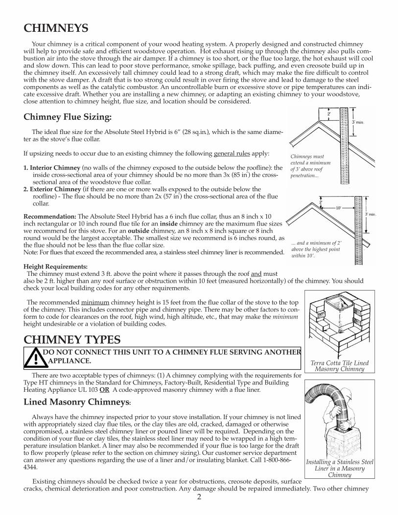
Height Requirements:The chimney must extend 3 ft. above the point where it passes through the roof and mustalso be 2 ft. higher than any roof surface or obstruction within 10 feet (measured horizontally) of the chimney. You shouldcheck your local building codes for any other requirements.
The recommended minimum chimney height is 15 feet from the flue collar of the stove to the topof the chimney. This includes connector pipe and chimney pipe. There may be other factors to con-form to code for clearances on the roof, high wind, high altitude, etc., that may make the minimumheight undesirable or a violation of building codes.
CHIMNEY TYPESDO NOT CONNECT THIS UNIT TO A CHIMNEY FLUE SERVING ANOTHERAPPLIANCE.
There are two acceptable types of chimneys: (1) A chimney complying with the requirements forType HT chimneys in the Standard for Chimneys, Factory-Built, Residential Type and BuildingHeating Appliance UL 103 OR A code-approved masonry chimney with a flue liner.
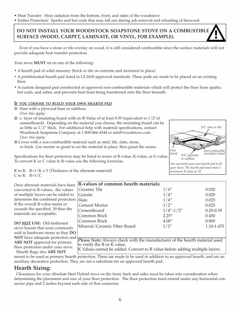
Lined Masonry Chimneys: Always have the chimney inspected prior to your stove installation. If your chimney is not lined
with appropriately sized clay flue tiles, or the clay tiles are old, cracked, damaged or otherwisecompromised, a stainless steel chimney liner or poured liner will be required. Depending on thecondition of your flue or clay tiles, the stainless steel liner may need to be wrapped in a high tem-perature insulation blanket. A liner may also be recommended if your flue is too large for the draftto flow properly (please refer to the section on chimney sizing). Our customer service departmentcan answer any questions regarding the use of a liner and/or insulating blanket. Call 1-800-866-4344.
Existing chimneys should be checked twice a year for obstructions, creosote deposits, surfacecracks, chemical deterioration and poor construction. Any damage should be repaired immediately. Two other chimney
Installing a Stainless SteelLiner in a Masonry
Chimney
Chimneys mustextend a minimumof 3’ above roof penetration...
... and a minimum of 2’above the highest point within 10’.
Terra Cotta Tile LinedMasonry Chimney
2

related areas that should be checked are chimney penetrations at the floor or ceiling joists, andat the roofline. There should be at least 2 inches of clearance between the chimney and floorjoists or other combustible materials. Poor flashing between the chimney and the roofline cancause leaks and deterioration of chimney mortar.
You should make preliminary checks, but if you have any doubts, or are unfamiliar withchimney construction, cleaning, or maintenance, have a local fire official or certified chimneyprofessional inspect your chimney. If repairs are required, be sure to use someone who isknowledgeable in chimney work and familiar with local code requirements.In addition: All brick or cinder block chimneys should have clean out access with a tightly fit-ting door. Masonry chimneys should have a wash at the top. All chimneys should have a cap tokeep out rain and snow and to minimize downdrafts caused by wind.
Passing Through A Combustible Wall:With an exterior chimney, in most cases the chimney connector (or stove pipe) will need to pass through a combustible
wall. The following are acceptable methods:
A. Use a section of Solid Insulated Prefabricated Metal Chimney to connect to the chimney - Use a section of insulatedprefabricated 2100° Class A chimney pipe listed to UL 103 HT (at least 1” of insulation or greater) the same inside diameteras the stove pipe and maintain a 9” air space between the wall of the prefabricated chimney and the combustible wall. Thissection of chimney pipe can be supported by a sheet metal plate securely fastened to the combustible wall, with a hole cut inthe middle of it. This will close the gap around the chimney pipe and the framed opening. (See Diagram A Above)
B. Build a solid brick surround around a tile liner - Frame a 3.5” thick brick surround into the combustible wall you need topass through. Maintain a minimum 12” brick separation from the clay liner to combustibles. The minimum 5/8” thick clayliner should be cemented in place and run from the outer surface of the brick to the inner surface of the chimney. (SeeDiagram B Above)
C. There are also UL Listed kits available that are specifically designed for passing through a combustible wall. For moreinformation on these kits, please contact Woodstock Soapstone Company. Please note: there are several UL listed wall passthrough kits available, always follow the specific manufacturers installation instructions. (See Diagram C Above)
For other methods, please refer to NFPA 211. REMEMBER, UNPROTECTED SINGLE OR DOUBLE WALL STOVE PIPE SHOULD NOT PASS THROUGH ACOMBUSTIBLE WALL OR CEILING TO CONNECT TO THE CHIMNEY. YOU MUST USE AN APPROVED METHODWHICH PROVIDES GREATER PROTECTION THAN SINGLE OR DOUBLE WALL PIPE.
Prefabricated Metal Chimneys: For high efficiency, freestanding woodstoves, like your Woodstock Soapstone stove, a Prefabricated
Metal Chimney must be listed as Class A and carry a UL Listing of 103 HT (high temperature). The “UL103 Type HT Class A” prefabricated chimney will have a temperature rating of 2,100° F. There are prefabricated chimney systems that are approved only to 1,700° F and are suitable only for
fireplace inserts or factory built fireplaces. DO NOT use these with your Woodstock Soapstone stove.At the point of the first penetration of a combustible surface (i.e., wall or ceiling) all subsequent
venting components need to be prefabricated “UL Type HT Class A”. If your prefabricated chimney goes through a living
Connecting your stove to amasonry thimble.
The minimum clearance for a single wallmetal stovepipe and terra cotta thimble at thechimney connection is 12”
A.
Using a Prefabricated Metal Chimney sectionto connect to an existing masonry chimneylocated behind a combustible wall Use a UL listed and approved wall pass thru kit.
B.
RefractoryCement
Insulatedsection offactory builtchimney
SheetSteelSupports
9”9”
9”
9
RefractoryCement
Fireclay Thimble
12”
12”12”12
Stainless Steel Connector
C.
UL listedinsulatedthimble
Minimum requiredair space
Listed wallprotector &cover shield
UL 103 HT StainlessChimney Connection
3

space it must be enclosed, and that enclosure must conform to clearance standards for the prefabricated chimney. Yourchimney must pass through your roof and extend above the roof line in accordance with code standards. Please refer toheight requirements on Page 2.
Prefabricated Chimney ConfigurationsThe diagrams below represent the most common and acceptable installations using prefabricated chimney pipe. The
necessary components are listed and shown in their appropriate locations. These components are Class A listed to U.L.103HT (tested to 2100 degrees F.) Only components listed to UL 103HT can be used to install your wood stove.Installation instructions are described below as examples only. More detailed instructions are available throughWoodstock Soapstone or the pipe manufacturer. ALWAYS FOLLOW THE SPECIFIC MANUFACTURER’S INSTALLA-TION INSTRUCTIONS.
Installation 1- Flat ceiling through the roof
First, determine where the stove will be placed. Pay close attention to all requiredclearances for the stove and connector pipe. Next, use a plumb line to locate the fin-ish ceiling support in the ceiling above. Cut the appropriate sized hole in the ceilingand frame in the necessary supports to secure the ceiling support. Install the pipeadapter onto the first section of chimney pipe, and lower them into the ceiling sup-port. Use an insulation shield in the attic to keep any insulation away from the pipe.If the attic is a living space the chimney pipe must be fully enclosed. As the pipeextends through the roof, install the appropriate flashing and storm collar to keep theweather out. As the height of the chimney increases to meet code, it may be neces-sary to install a roof brace (typically recommended at 5’ intervals). All chimneysshould have the appropriate cap installed at the top to reduce wind and weatherrelated downdrafts as well as deter any animals from building nests. The connectorpipe should extend from the flue collar of the stove to the pipe adapter at the ceilingsupport. The male (crimped) end should always point down toward the stove. Besure that each joint has enough overlap for a secure connection. All connections should be fastened with screws, includingat the flue collar and pipe adapter. (Please refer to the manufacturers full set of installation instructions).
Installation 2- Pitched/Cathedral Ceiling through the roof
Determine where the stove will be placed. Be sure all clearance requirements aresatisfied. Choose the appropriate support for your installation (support box or roofsupport). Use a plumb line to locate the support in the ceiling above. Cut the appro-priate sized hole in the ceiling and install the necessary framing to secure the sup-port. Install the support according to its specific instructions. Be sure that the sup-port hangs down below the ceiling far enough to maintain proper clearance for theconnector pipe (steeper slopes require more chimney pipe below the ceiling). Installthe pipe adapter to the first section of chimney pipe and lower it into the supportbox (or connect it to the bottom of the roof support). As the pipe extends throughthe roof, install the appropriate roof flashing and storm collar. Install the properchimney pipe lengths to meet code and recommended chimney height. It may benecessary to install a roof brace for stability. Always install the appropriate cap tothe top of the chimney. Double wall connector pipe is recommended for installa-tions that have 8’ or more from the stove to the chimney. Be sure that all joints inthe connector pipe are secure and fastened with screws, including at the flue collarand chimney pipe adapter. (Please refer to the manufacturers full set of installation instructions).
Installation 3- Through the wall
This installation requires the use of an insulated wall thimble to penetrate a com-bustible wall. Typically a 9”-12” chimney pipe and pipe adapter will pass throughthe thimble and make the connection between the interior connector pipe and aninsulated tee with a clean out on the outside of the bulding. The tee and chimneyrising up from it rest on a wall support designed to bear the weight of the chimney.Install lateral supports as specified as the chimney rises along the exterior wall. Theappropriate flashing and storm collar should be installed if the chimney penetratesan eave or overhang. An offset of 15 or 30 degrees may also be used to go around anoverhang. As the chimney extends above the roof to meet code recommendedheights it may be necessary to install a roof brace. (Please refer to the manufacturersfull set of installation instructions).
Installation 1- Flat ceiling through the roof
Installation 2 Pitched/Cathedral Ceiling through the roof.
Class A Chimney Pipe
Installation 3- Through the Wall
Attic Insulation Shield
4
Chimney Cap
Chimney Cap
Chimney Cap
Flashing & Storm Collar

Stovepipe (Connector Pipe):Connector pipe is either single wall (sheet metal) or double wall (sheet metal outer pipe with a stainless steel inner
pipe). We strongly recommend 22 gauge pipe (26 or 28 gauge is too thin for use with a woodstove). The connector pipeshould be 6 inch diameter to match the flue collar of the stove. If your connection to either a masonry chimney or prefab-ricated chimney system is more than 8 feet tall, we recommend the use of double wall connector pipe. If you need toreduce clearances for your connector pipe installation, double wall connector pipe would be recommended. All pipe con-nections, including at the flue collar, must be secured with screws. DO NOT USE GALVANIZED SINGLE WALL PIPE.
Connector pipe is designed to connect your stove to your masonry lined or approved prefabricated chimney system.CONNECTOR PIPE SHOULD NEVER BE USED AS A CHIMNEY AND SHOULD NEVER PASS THROUGH ACOMBUSTIBLE WALL, CEILING, WINDOW, CLOSET, OR ROOF. At the point where your stovepipe meets thechimney, you must either vent into a masonry chimney with approved non-combustible transition, or a prefabricatedchimney system with a specially designed transition piece.
FIREPLACE INSTALLATIONYour Model 211 Absolute Steel Hybrid Woodstove has an option of rear venting. The
centerline height of the rear flue is 28”, in order for the exiting pipe to clear the fire-place lintel, the opening height will need to be 31” or greater. Installing the AbsoluteSteel Hybrid stove in a fireplace setting is a great way to enjoy the view of the fire,while greatly increasing the efficiency and reducing heat loss to the fireplace chimney.
We do not recommend placing the stove inside the fireplace, as it would make rou-tine maintenance such as cleaning the combustor more difficult, and much of the heatradiating off the stove would not circulate into the room.
The preferred method for installing a stove in front of a fireplace is by running astainless steel ‘flex’ liner down the chimney, connecting it to the stove at the fire-place. Chimneys with large flues should be relined to achieve proper draft. If thechimney does not have flue tiles or if the tiles are cracked or compromised, an addi-tional insulating material must be used.
It is important that there be a secure connection between the stove and the flueliner. It is NOT acceptable to simply install a plate in front of the fireplace and runa stovepipe through it. The stove pipe must connect with the liner for a continuousoutlet to the top of your chimney.
Stainless steel flex liner kits come in a variety of lengths and are readily avail-able. These kits include a flexible stainless steel pipe, tee with snout & clean out, ablock-off plate for the top of the chimney, and a cap. Please contact WoodstockSoapstone Company for more information on these kits. ALWAYS FOLLOW THESPECIFIC MANUFACTURER’S INSTALLATION INSTRUCTIONS.
If the fireplace surround is clad in wood trim, the proper clearance to a com-bustible will need to be maintained. Please refer to the clearance charts on pages 8-10. An unprotected wood mantel needs to be a minimum of 30” from the top of thestove. If a mantel shield is installed that clearance can be reduced to 12”.
DO NOT VENT YOUR WOOD STOVE THROUGH A FACTORY BUILT FIRE-PLACE UNLESS IT IS SPECIFICALLY LISTED FOR SUCH AN INSTALLATIONMost factory-built fireplace chimney systems are only rated to 1,700° F, which is notsufficient for a freestanding wood burning stove.
FLOOR PROTECTION REQUIREMENTSYour Woodstock Soapstone stove must be set on an approved hearth or floor protection.
The hearth protects your floor from two hazards:
Cap
Top Plate
StainlessLiner
CleanoutTee & Snout
Components of a standard liner kit: Tee with clean out& snout, stainlessflex liner, top block-off plate & cap.
5
Minimum of 31” of vertical opening for6” pipe to pass under the fireplace lintel.
31”
• Heat Transfer: Heat radiation from the bottom, front, and sides of the woodstove• Ember Protection: Sparks and hot coals that may fall out during ash removal and reloading of firewood
DO NOT INSTALL YOUR WOODSTOCK SOAPSTONE STOVE ON A COMBUSTIBLE SURFACE (WOOD, CARPET, LAMINATE, OR VINYL, FOR EXAMPLE).
Even if you have a stone or tile overlay on wood, it is still considered combustible since the surface materials will notprovide adequate heat transfer protection.
Your stove MUST sit on one of the following:
• A hearth pad of solid masonry (brick or tile on concrete and mortared in place)• A prefabricated hearth pad listed to UL1618 approved standards. These pads are made to be placed on an existingfloor. • A custom designed pad constructed of approved non-combustible materials which will protect the floor from sparks,hot coals, and ashes; and prevents heat from being transferred onto the floor beneath.
IF YOU CHOOSE TO BUILD YOUR OWN HEARTH PAD1) Start with a plywood base or subfloor.
Over this apply:2) a layer of insulating board with an R-Value of at least 0.39 (equivalent to 1/2”ofcementboard). Depending on the material you choose, the insulating board can beas little as 1/2” thick. For additional help with material specifications, contactWoodstock Soapstone Company at 1-800-866-4344 or [email protected] this apply:
3) Cover with a non-combustible material such as steel, tile, slate, stone,or brick. Use mortar or grout to set the material in place, then grout the seams.
Specifications for floor protectors may be listed in terms of R-value, K-value, or C-value.To convert K or C value to R-value use the following formulas.
K to R: R=1/K x T (Thickness of the alternate material)C to R: R=1/C
Once alternate materials have beenconverted to R-values, the valuesof multiple layers can be added todetermine the combined protection.If the overall R-value meets orexceeds the specified .39 then thematerials are acceptable.
DO NOT USE: Old-fashionedstove boards that were commonlysold in hardware stores as they DONOT have adequate protection andARE NOT approved for primaryfloor protection under your stove. Hearth Rugs also ARE NOTmeant to be used as primary hearth protection. These are made to be used in addition to an approved hearth, and are anauxiliary decorative protection. They are not a substitute for an approved hearth pad.Hearth Sizing:Clearances for your Absolute Steel Hybrid stove on the front, back and sides must be taken into consideration whendetermining the placement and size of your floor protection. The floor protection must extend under any horizontal con-nector pipe and 2 inches beyond each side of that connector.
You can build your own hearth pad to fityour decor. The hearth pad must meet aminimum R value of .41
trimboard
1/4” slate or tile
3/4” plywoodor subfloor
non-combustibleinsulation board
6
R-values of common hearth materials:Ceramic Tile 1/4” 0.020Granite 1/4” 0.020Slate 1/4” 0.025Cement Mortar 1/2” 0.025Cementboard 1/4”-1/2” 0.20-0.39Common Brick 2.25” 0.450Common Brick 4.00” 0.800Mineral/Ceramic Fiber Board 1/2” 1.10-1.470
Please Note: Always check with the manufacturer of the hearth material usedto verify the R or K value. K Values cannot be added. Convert to R value before adding multiple layers.

PARALLEL HEARTH PAD
MINIMUM DIMENSIONSA. Floor protection in front stove = 6” B. Protection on loading door side = 16” C. Floor protection non-loading door sides = 6”D. Floor protection behind stove (top vent or rear
vent) = 6”E. Floor protection under pipe when rear vented must
extend under any horizontal connector pipe and 2 inches beyond each side of that connector.
Minimum hearth size in a parallel installation is 36.5”D x 46.5”W.Recommended size is 40” D x 57”W or larger.
A 38.5” x 57” rectangular hearth pad will allow for8” behind the stove, 16” on either side, and 8”in front of the stove. The hearth pad must have a minimumR value of 0.39 (1/2” of “cementboard” covered with non-combustible material such as sheet metal,tile or stone).
CORNER HEARTH PAD Minimum hearth size in a corner installation must be 54”x54” (with the front corner cut off). NOTE: On a hearth of minimum size, the stove will not be centered left to right, but willmeet the minimum required clearances.
Calculating a Corner Hearth Pad (per NFPA 211):A=C x 1.414 + W/2 + D + Front Hearth RequirementA =distance from corner to the front of the hearth padC = clearance from rear corner of appliance to wall (6” w/ rear heatshield)1.414 = a constantW/2 = one half the appliance width (12.25”)D = appliance depth (22.5”)Front Hearth Clearance= 6”
Example:Absolute Steel with the Rear Heat Shield & Pipe ShieldA= 18” x 1.414 + 12.25 + 22.5”+6” A= 66.2”
WALL PROTECTIONThe Model 211 Absolute Steel Hybrid stove has been tested to UL stan-dards for clearances to combustible walls. The minimum clearances tounprotected walls are as follows:
Minimum clearances with no heat shields to unprotected combustible walls:From the back------------------ 14”From the sides------------------ 26”DO NOT ASSUME THAT A WALL IS NOT COMBUSTIBLE BECAUSE IT HAS A NONFLAMMABLE SURFACE.
A wall with any combustible materials in it must be considered combustible. For example, a brick wall attached to woodstuds is considered a combustible wall. Over time, heat will pass through bricks and heat the wood, lowering the igni-tion temperature of the studs, possibly resulting in a fire. As waves of radiant heat energy meet a combustible object,heat is absorbed and the temperature of the object is raised, which can result in spontaneous combustion. Similarly,wood-framed walls which are covered with tile, stone or fire-rated sheetrock must be considered combustible. Fire-ratedsheetrock is also considered combustible due to the paper covering.If you wish to install your stove closer to a combustible wall than standard clearances will permit, you can either attachan approved stove & pipe shield, or mount a ventilated, non-combustible shield on the wall.
PARALLEL HEARTH PADMeasurements taken from stove body
Stove Body Width 24.5” Stove Body Depth 22.5”
A=66.2”
54”
54”
40”
20”CORNER HEARTH PADAbsolute Steel Hybrid shownabove centered left to right
7
A
B
D/E
C

Stove and Pipe Shields:Clearances can be reduced by attaching an approved heat shield, Part R-997 and pipe shield,
part #W-413. Woodstock Soapstone Company carries heat shields specifically designed for thisstove. When using one or both of these shields, clearance is measured from the back of theshield to the combustible wall. The clearance behind the stove can be reduced to 8.5 inches.The clearance behind the pipe can be reduced to 6 inches.
Clearance Table:The Absolute Steel Hybrid can be installed at a 14” clearance with no additional protection, if
the stove pipe is top vented, and the provided shield is installed on the inside of the rear fluecover plate. To further reduce the rear clearance to 8.5”, you must attach an approved rear heatshield and a 24” pipe shield.
*These clearance reductions meet or exceed requirements of NFPA 211, Standard for Chimneys, Fireplaces, Vents, and Solid FuelBurning Appliances. Approved NFPA 211 clearance reduction methods DO NOT allow stove clearances to be reduced below 12”.NFPA WALL SHIELDS MUST BE SIZED TO NFPA 211 SPECIFICATIONS. CONSULT NFPA 211 AND A QUALIFIED EXPERTBEFORE IMPLEMENTING THESE REDUCTIONS. The only approved method allowing for a rear stove clearance less than 12” is the Approved Rear Heat Shield (#R-997) provided byWoodstock Soapstone Co. If your installation requires the use of the Approved Rear Heat Shield call 1-800-866-4344.
• These clearances apply to walls, ceilings, furniture and other combustibles.• The 24” Vertical Stack Shield attaches to the back of the stove pipe and prevents excess heat from being radiated from the pipe.Heat shield protection is only required for the first 24” of vertical connector pipe.
• At least 30” is required from the front of the stove to combustibles (such as curtains, wall hangings, and furniture).
The same clearances from your stove and stove pipe apply to both fireplace and freestanding installations. Beparticularly careful to check clearances to a wood mantel or a wood fireplace facade. You must maintain a 30” clearanceto an unprotected wood mantel. See Fireplace Installations on Page 5.
8
Rear heat shield & pipeshield reduce requiredrear clearance to 8.5”
Clearance Table For Model 211 Absolute Steel Type of Installationu Top Vent Rear Vent Rear Vent with elbow Stove Sides
Stoveck Pipe goes
Type of protectionqStove Back Stovepipe
No Protection 14” 14” 23.5”* 15.5” 26”With 24” Pipe Shield 18” 10” 26”With Approved Rear Heat Shield, 8.5” 18” 10”* 16”24” Pipe Shield & Side Shield 3 1/2” thick Masonry Against 12” 12” 20” 12” 13”Combustible Wall*3 1/2” thick Masonry with 12” 12” 14” 6” 12”1” ventilated airspace*24 ga. sheet metal with 12” 12” 14” 6” 12”1” ventilated airspace*1/2” thick non-combustible 12” 12” 14” 6” 12”insulation board with 1” airspace*
Clearance fromstove back, topvent, withstove pipewhich goesstraight up
Clearancefrom stoveback and pipe,which goesstraight back
Clearance from stove backand vertical single wallconnector pipe with elbow at stove back
See note below regarding NFPA211 clearance reduction methodsand implementation.See note below regarding NFPA211 clearance reduction methodsand implementation.See note below regarding NFPA211 clearance reduction methodsand implementation.See note below regarding NFPA211 clearance reduction methodsand implementation.
*Controlling clearance
CLEARANCE INSTALLATION DIAGRAMS
B
C
C
A
B
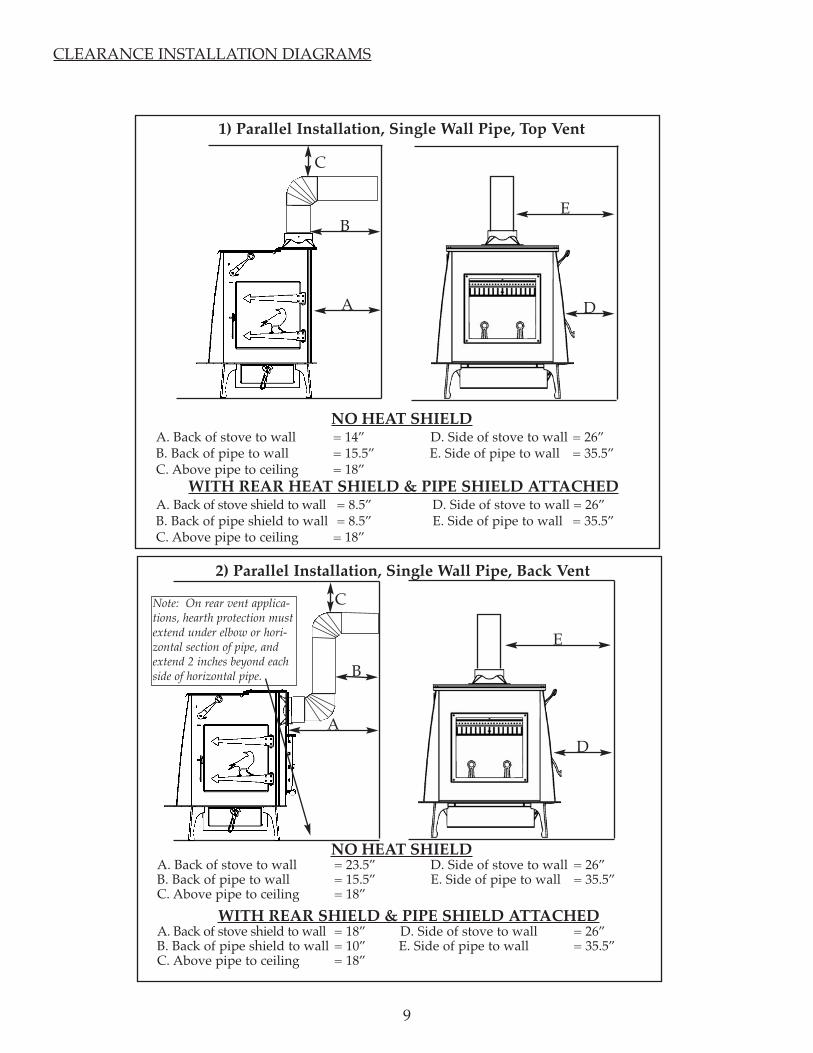
2) Parallel Installation, Single Wall Pipe, Back Vent
WITH REAR HEAT SHIELD & PIPE SHIELD ATTACHEDA. Back of stove shield to wall = 8.5” D. Side of stove to wall = 26”B. Back of pipe shield to wall = 8.5” E. Side of pipe to wall = 35.5”C. Above pipe to ceiling = 18”
9
NO HEAT SHIELDA. Back of stove to wall = 14” D. Side of stove to wall = 26”B. Back of pipe to wall = 15.5” E. Side of pipe to wall = 35.5”C. Above pipe to ceiling = 18”
1) Parallel Installation, Single Wall Pipe, Top Vent
A
E
E
D
D
NO HEAT SHIELDA. Back of stove to wall = 23.5” D. Side of stove to wall = 26”B. Back of pipe to wall = 15.5” E. Side of pipe to wall = 35.5”C. Above pipe to ceiling = 18”
WITH REAR SHIELD & PIPE SHIELD ATTACHEDA. Back of stove shield to wall = 18” D. Side of stove to wall = 26”B. Back of pipe shield to wall = 10” E. Side of pipe to wall = 35.5”C. Above pipe to ceiling = 18”
Note: On rear vent applica-tions, hearth protection mustextend under elbow or hori-zontal section of pipe, andextend 2 inches beyond eachside of horizontal pipe.
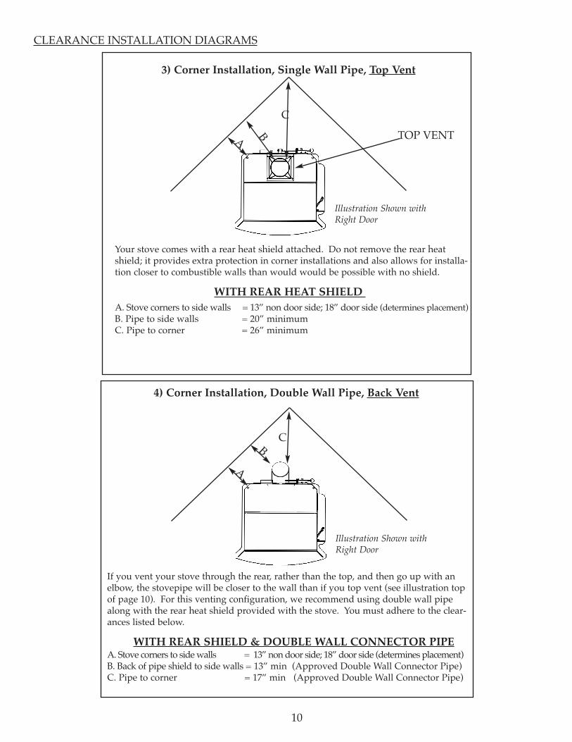
If you vent your stove through the rear, rather than the top, and then go up with anelbow, the stovepipe will be closer to the wall than if you top vent (see illustration topof page 10). For this venting configuration, we recommend using double wall pipealong with the rear heat shield provided with the stove. You must adhere to the clear-ances listed below.
WITH REAR SHIELD & DOUBLE WALL CONNECTOR PIPEA. Stove corners to side walls = 13” non door side; 18” door side (determines placement) B. Back of pipe shield to side walls = 13” min (Approved Double Wall Connector Pipe)C. Pipe to corner = 17” min (Approved Double Wall Connector Pipe)
4) Corner Installation, Double Wall Pipe, Back Vent
CTOP VENT
Your stove comes with a rear heat shield attached. Do not remove the rear heatshield; it provides extra protection in corner installations and also allows for installa-tion closer to combustible walls than would would be possible with no shield.
WITH REAR HEAT SHIELD A. Stove corners to side walls = 13” non door side; 18” door side (determines placement)B. Pipe to side walls = 20” minimum C. Pipe to corner = 26” minimum
3) Corner Installation, Single Wall Pipe, Top Vent
CLEARANCE INSTALLATION DIAGRAMS
10
BA
Illustration Shown withRight Door
C
A
Illustration Shown withRight Door
B

Because mobile homes are also referred to by HUD as“manufactured” homes, regulations present a gray area.Many “mobile” homes are set on a permanent foundationand connected to public utilities. If you are installing astove in a mobile or manufactured home, check out therequirements below and check with your local code offi-cials. More questions? Give us a call Monday throughSaturday from 9 to 5 Eastern time at 1-800-866-4344.While all stove installations have to meet National FireSafety codes, mobile homes are given special considerationwhen it comes to installing a wood burning stove. Theseadditional regulations were established by the Departmentof Housing and Urban Development (HUD), and result inthe following additional requirements:
1. Double Wall Connector Pipe 2. Outside Air for Combustion 3. Tie Downs for the Stove 4. Spark Arrestor on the Chimney Cap 5. Stove Grounded to Chassis6. Stoves May Not Be Installed in Mobile Home Bedrooms
Double wall pipe must be used to connect the stove to thechimney. This is stove pipe that is constructed with twowalls, usually with the inner wall made of stainless steel. Itreduces the required clearance to combustible buildingmaterials and furnishings.Outside Air must be used for combustion. Because of thetight construction of mobile homes, wood stoves need away to get adequate air from outside the home for com-plete combustion in order to avoid the risk of depletingoxygen in the living space. Having outside air for combus-tion is a requirement for all woodburning stoves in thestate of Washington and is recommended for woodstovesin “super tight” new construction.Tie Downs: The stove must be attached to the floor. Thisis to prevent tipping in the event the home is moved. (Wecan provide tie downs for our stoves at no extra charge). Spark Arrestor: The chimney cap must have a sparkarrestor screen. These are available with most prefabricatedchimney systems. Grounding: The stove should be grounded to the homechassis.
Not allowed in mobile home bedrooms: wood stoves arenot permitted for installation in bedrooms in mobilehomes.
The Outside Air Adapteris built into the design ofthe Absolute Steel Hybrid,and is located at the backof the stove. It has a four-inch collar which allowsyou to attach a four inchpipe, usually flexible dryerduct, from the stove to theoutside. For long runs, theflexible pipe can transitionto PVC or aluminum pipe,if you wish.
Mobile home with pitched roof
MOBILE HOME INSTALLATIONCAUTION: THE STRUCTURAL INTEGRITY OF THE MOBILE HOME FLOOR, WALL, AND CEILING/ROOFMUST BE MAINTAINED.
Woodstock Soapstone Company66Airpark Road, West Lebanon, NH 03784800-866-4344 • www.woodstove.com
Mobile Home Prohibition:WARNING:
DO NOT INSTALL IN SLEEPING ROOMFinish Ceiling Support
Grounding
Chimney Cap with SparkArresterClass A ChimneyFlashing/Storm Collar
Mobile home installations require a number of spe-cial considerations, including dedicated outside air,tie-downs, and grounding to the chassis of themobile home.
11
Outside Air Adapter
Tie-Downs
Attic Insulation Shield
Double Wall ConnectorPIpe
Outside Air Adapter andDuct

12
SETTING UP YOUR STOVEYour Model 211 Absolute Steel Hybrid woodstove has been shipped assembled except for two parts:
1) The flue collar and cover plate, including the internal cover plate shield. 2) Required bottom heat shield.All necessary hardware and instructions are also packed in the firebox. Any optional items such as heat shields will bepacked separately.
1) How to attach the Absolute Steel Hybrid flue collar & cover plate, and the coverplate shield:The Absolute Steel Hybrid is designed to be vented out the top or out the rear with an
easily convertible flue collar and cover plate. Each part is secure to the stove body with 4bolts. You will need a 7/16” wrench or socket and ratchet to install these parts. The stoveis shipped with the cover plate installed over the rear flue exit with an internally mountedheat shield. The flue collar is packed inside the firebox.
1. Decide which way you would like to vent your stove. This may be dependent onthe location of an existing chimney or the design of an existing hearth. Always payclose attention to required clearances when considering stove placement
TOP VENTING:
1. If you are top venting, use the (4) bolts supplied making sure that the gasket on itis secure and stays in place while installing. Use four of the bolts to attach the fluecollar to the stove body. The holes in the stove body are threaded to accept thebolts. Alternate between the bolts while tightening to ensure even pressure. Thebolts should be tight enough to firmly compress the gasket. Do not over tighten.
REAR VENTING:
1. If you are rear venting, the cover plate has an internally mounted stainless steel heat shield. Two of the fourmounting bolts are longer to accommodate this shield and are diagonally opposite each other. Remove the (2) hexnuts from these longer bolts using a 7/16” wrench or socket. Remove the shield and set the shield and nuts asidefor reuse.
2. Remove the (4) mounting bolts from the cover plate and transfer the cover plate to the top of the stove. Install the(2) longer bolts diagonally opposite from each other (doesn’t matter which 2 holes). Working through the back flueopening, reinstall the heat shield and snug it down with the (2) nuts. Install the remaining shorter (2) bolts.
3. You can now install the flue collar on the rear of the stove using the (4) 1/4-20 hex bolts supplied.
2) Installation of the required bottom heat shield:The Absolute Steel Hybrid was tested and listed with the use of the bottom heat shield. The bottom heat shield MUSTbe installed prior to lighting the first fire. The attachment instructions can be used for both the ash pan and non-ash panversions of the Absolute Steel Hybrid. If your stove DOES NOT have an ash pan, the shield will be flat sheet metalinstead of formed sheet metal.
1. Locate the (4) 1/4-20 studs welded to the bottom of the stove. The studscan be found in each corner, just behind each leg. With the attachmentflanges facing up, slide the heat shield under the stove centered on theash pan housing. The shield is symmetrical so there is no front or back.
2. Each attachment flange has (2) holes, one on each end. Align these holeswith the studs and push the shield up over the studs. It may be easier tohave a helper during this step.
3. Thread (1) 1/4-20 nut on each stud. 2-3 threads is all that’s necessary asyou want the shield to drop down and rest on the nuts, this will leave asmall air gap. DO NOT affix the shield firmly to the bottom of the stove.
Image above shows a top mountedflue collar and rear cover plate