Flue installation instructions - Vaillant UK · Flue installation instructions ... Alternative...
44
For the installer Flue installation instructions Air flue duct for use with ecoMAX ecoMAX 613/2 E ecoMAX 618/2 E ecoMAX 622/2 E ecoMAX 824/2 E ecoMAX 828/2 E ecoMAX 835/2 E ecoMAX pro 18 E ecoMAX pro 28 E GB 2000225123A-10.02
Transcript of Flue installation instructions - Vaillant UK · Flue installation instructions ... Alternative...
For the installer
Flue installation instructions
Air flue duct for use with ecoMAX ecoMAX 613/2 E
ecoMAX 618/2 E
ecoMAX 622/2 E
ecoMAX 824/2 E
ecoMAX 828/2 E
ecoMAX 835/2 E
ecoMAX pro 18 E
ecoMAX pro 28 E
GB
2000225123A-10.02

2
OVERVIEW
3
PART
2 C
ONC
ENTR
IC 8
0/12
5
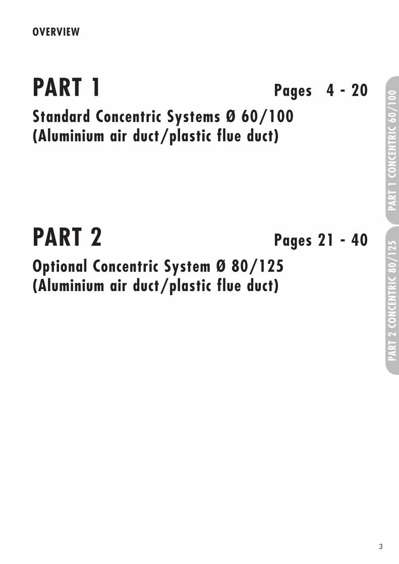
PART 1 Pages 4 - 20
Standard Concentric Systems Ø 60/100(Aluminium air duct/plastic flue duct)
PART 2 Pages 21 - 40
Optional Concentric System Ø 80/125(Aluminium air duct/plastic flue duct)
PART
2 C
ONC
ENTR
IC 8
0/12
5PA
RT 1
CO
NCEN
TRIC
60/
100
4
CONTENTS: PART 1 CONCENTRIC 60/100
Page
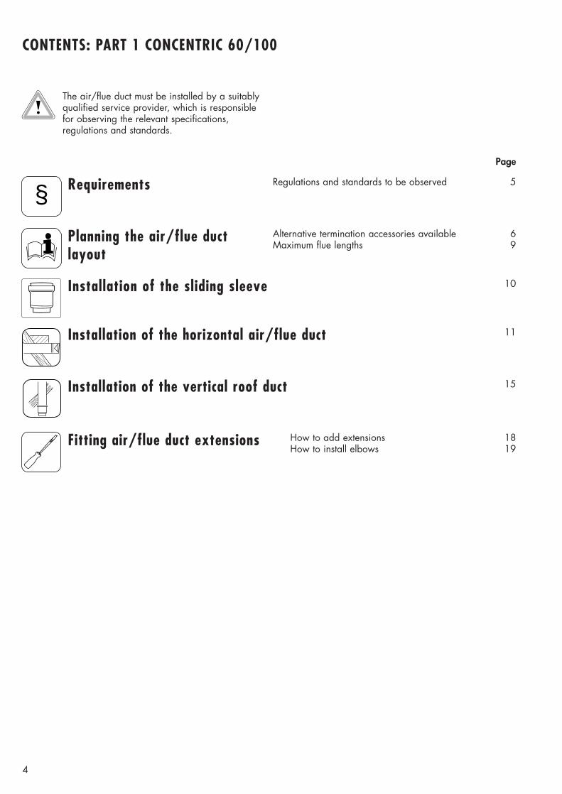
The air/flue duct must be installed by a suitablyqualified service provider, which is responsiblefor observing the relevant specifications,regulations and standards.
Requirements
Planning the air/flue duct layout
Regulations and standards to be observed 5
Alternative termination accessories available 6Maximum flue lengths 9
§
Installation of the vertical roof duct 15
Installation of the horizontal air/flue duct 11
Fitting air/flue duct extensions
Installation of the sliding sleeve
How to add extensions 18How to install elbows 19
10
5
PART
1 C
ONC
ENTR
IC 6
0/10
0
REQUIREMENTS
Regulations andstandards to beobserved
§
☞ Vaillant ecoMAX boilers arecertified as heating boilers with corresponding flue systems according to EC Directive90/396/EEC on gas-fireddevices. This installation manual iscovered by this certification and isreferred to in the design approvaltest certificate.
☞ These instructions should be readin conjunction with the instructionsfor installation and servicing supplied with the boiler.
☞ Ensure also that all legislation,rules, regulations and directivesmentioned in the installationinstructions are observed.
☞ The installation of the boiler andits flue must be carried out by acompetent person who is registered with CORGI (TheCouncil for Registered GasInstallers).
☞ The installation of the boiler andflue must be in accordance withthe Gas Safety (Installation andUse) Regulations 1998 and theBuilding Regulations and BS 5440 Part 1.
☞ The requirements for flue termination detailed in the boilerinstallation instructions must beobserved.
☞ Two types of flue system are available for ecoMAX boilers. Thestandard concentric flue system(100 mm outside diameter) and alarger diameter concentric system(125 mm outside diameter) whichallows longer air/flue duct lengthsto be achieved.
☞ The air/flue duct operates at verylow temperatures therefore noclearance is necessary betweenthe air duct and adjacent services.
☞ Ensure while installation work isbeing carried out that no debrissuch as swarf, filings or fragmentsof mortar are allowed to remainin the air/flue duct.
Optional connection accessories
Offset section
Telescopic extension440 mm - 690 mm Ø 60/100
6
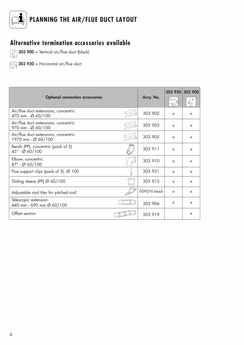
PLANNING THE AIR/FLUE DUCT LAYOUT
Alternative termination accessories available
Air/flue duct extensions, concentric470 mm - Ø 60/100
Air/flue duct extensions, concentric970 mm - Ø 60/100
Air/flue duct extensions, concentric1970 mm - Ø 60/100
Bends (PP), concentric (pack of 2)45° - Ø 60/100
Elbow, concentric87° - Ø 60/100
Flue support clips (pack of 5), Ø 100
Sliding sleeve (PP) Ø 60/100
Adjustable roof tiles for pitched roof
303 900 = Vertical air/flue duct (black)
303 930 = Horizontal air/flue duct
Accy. No.303 930 303 900
303 919
303 906
303 902 x
303 903 x
303 905 x
303 911 x
x
303 910 x
303 921 x
303 915 x
009076 black x
x
x
x
x
x
x
x
x
x
x
7
PART
1 C
ONC
ENTR
IC 6
0/10
0
PLANNING THE AIR/FLUE DUCT LAYOUT
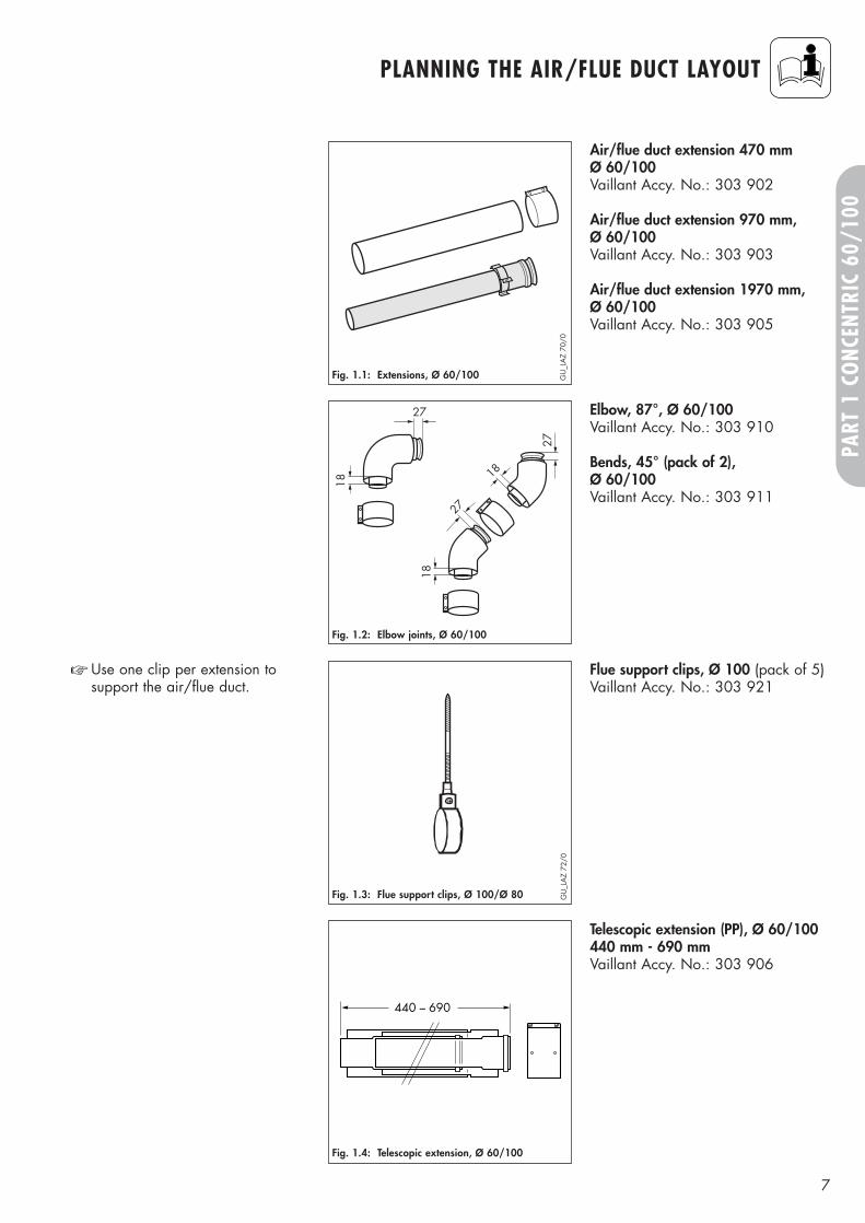
Fig. 1.1: Extensions, Ø 60/100
Fig. 1.3: Flue support clips, Ø 100/Ø 80
Flue support clips, Ø 100 (pack of 5)Vaillant Accy. No.: 303 921
☞ Use one clip per extension to support the air/flue duct.
18
2718
27
18
27
Fig. 1.2: Elbow joints, Ø 60/100
Elbow, 87°, Ø 60/100Vaillant Accy. No.: 303 910
Bends, 45° (pack of 2), Ø 60/100Vaillant Accy. No.: 303 911
Air/flue duct extension 470 mm Ø 60/100Vaillant Accy. No.: 303 902
Air/flue duct extension 970 mm, Ø 60/100Vaillant Accy. No.: 303 903
Air/flue duct extension 1970 mm, Ø 60/100 Vaillant Accy. No.: 303 905
GU
_LA
Z 70
/0
GU
_LA
Z 72
/0
440 – 690
Fig. 1.4: Telescopic extension, Ø 60/100
Telescopic extension (PP), Ø 60/100440 mm - 690 mmVaillant Accy. No.: 303 906
8
PLANNING THE AIR/FLUE DUCT LAYOUT
155
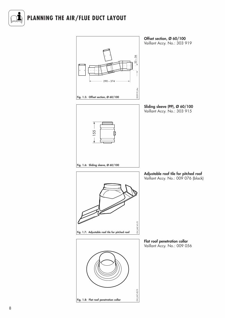
Fig. 1.6: Sliding sleeve, Ø 60/100
Sliding sleeve (PP), Ø 60/100 Vaillant Accy. No.: 303 915
290 – 374
33 –
56
Fig. 1.5: Offset section, Ø 60/100
Offset section, Ø 60/100Vaillant Accy. No.: 303 919
3039
19_I
Ax
Fig. 1.8: Flat roof penetration collar GU
_LA
Z 42
/0
Flat roof penetration collarVaillant Accy. No.: 009 056
Fig. 1.7: Adjustable roof tile for pitched roof
Adjustable roof tile for pitched roofVaillant Accy. No.: 009 076 (black)
GU
_LA
Z 41
/0
9
PART
1 C
ONC
ENTR
IC 6
0/10
0
PLANNING THE AIR/FLUE DUCT LAYOUT
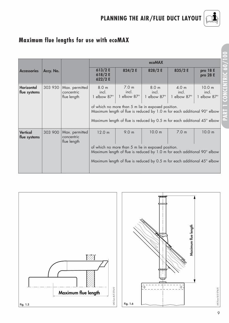
Maximum flue lengths for use with ecoMAX
Maximum flue length
Max
imum
flue
leng
th
LAS
Euro
B/S
074
/0
LAS
Euro
B/S
074
/0
Fig. 1.5 Fig. 1.6
Accessories Accy. No.
Vertical flue systems
303 900 Max. permitted concentric flue length
Horizontal flue systems
303 930 Max. permittedconcentricflue length
12.0 m
8.0 mincl.
1 elbow 87°
828/2 E 835/2 E pro 18 Epro 28 E
10.0 m 7.0 m 10.0 m
8.0 mincl.
1 elbow 87°
4.0 mincl.
1 elbow 87°
10.0 mincl.
1 elbow 87°
824/2 E
9.0 m
7.0 mincl.
1 elbow 87°
613/2 E618/2 E622/2 E
ecoMAX
of which no more than 5 m lie in exposed position.Maximum length of flue is reduced by 1.0 m for each additional 90° elbow
Maximum length of flue is reduced by 0.5 m for each additional 45° elbow
of which no more than 5 m lie in exposed position.Maximum length of flue is reduced by 1.0 m for each additional 90° elbow
Maximum length of flue is reduced by 0.5 m for each additional 45° elbow
10
INSTALLING THE AIR/FLUE DUCT SLIDING SLEEVE
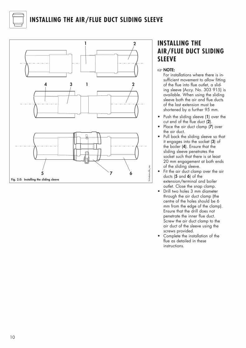
Fig. 2.0: Installing the sliding sleeve
1 2
3 1 24
5 67
Schi
ebem
uffe
_neu
INSTALLING THEAIR/FLUE DUCT SLIDINGSLEEVE☞ NOTE:
For installations where there is in-sufficient movement to allow fittingof the flue into flue outlet, a slid-ing sleeve (Accy. No. 303 915) isavailable. When using the slidingsleeve both the air and flue ductsof the last extension must beshortened by a further 95 mm.
• Push the sliding sleeve (1) over thecut end of the flue duct (2).
• Place the air duct clamp (7) overthe air duct.
• Pull back the sliding sleeve so thatit engages into the socket (3) ofthe boiler (4). Ensure that thesliding sleeve penetrates thesocket such that there is at least20 mm engagement at both endsof the sliding sleeve.
• Fit the air duct clamp over the airducts (5 and 6) of theextension/terminal and boileroutlet. Close the snap clamp.
• Drill two holes 3 mm diameterthrough the air duct clamp (thecentre of the holes should be 6mm from the edge of the clamp).Ensure that the drill does notpenetrate the inner flue duct.Screw the air duct clamp to theair duct of the sleeve using thescrews provided.
• Complete the installation of theflue as detailed in theseinstructions.
11
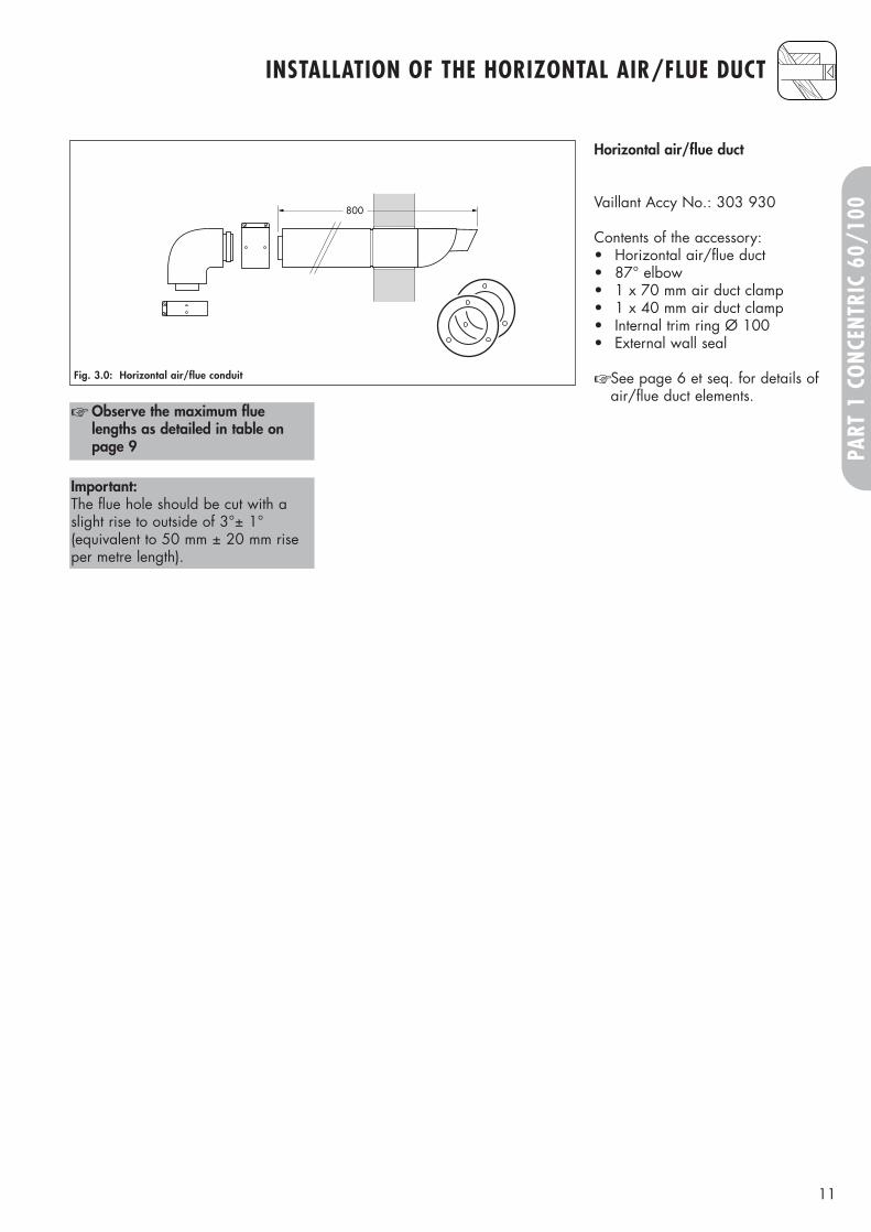
800
☞ Observe the maximum fluelengths as detailed in table onpage 9
Horizontal air/flue duct
Vaillant Accy No.: 303 930
Contents of the accessory:• Horizontal air/flue duct• 87° elbow• 1 x 70 mm air duct clamp• 1 x 40 mm air duct clamp• Internal trim ring Ø 100• External wall seal
☞ See page 6 et seq. for details ofair/flue duct elements.
Fig. 3.0: Horizontal air/flue conduit
Important:The flue hole should be cut with aslight rise to outside of 3°± 1°(equivalent to 50 mm ± 20 mm riseper metre length).
INSTALLATION OF THE HORIZONTAL AIR/FLUE DUCT
PART
1 C
ONC
ENTR
IC 6
0/10
0
12
INSTALLATION OF THE HORIZONTAL AIR/FLUE DUCT
Horizontal air/flue duct
Accy No.: 303 930(Length 0.8 m)
Contents of the accessory:• Horizontal air/flue duct• 87° elbow• 2 x 70 mm air duct clamps• 1 x 40 mm air duct clamp• Internal trim ring Ø 100• External wall seal.
Fig. 3.1: Horizontal air/flue conduit
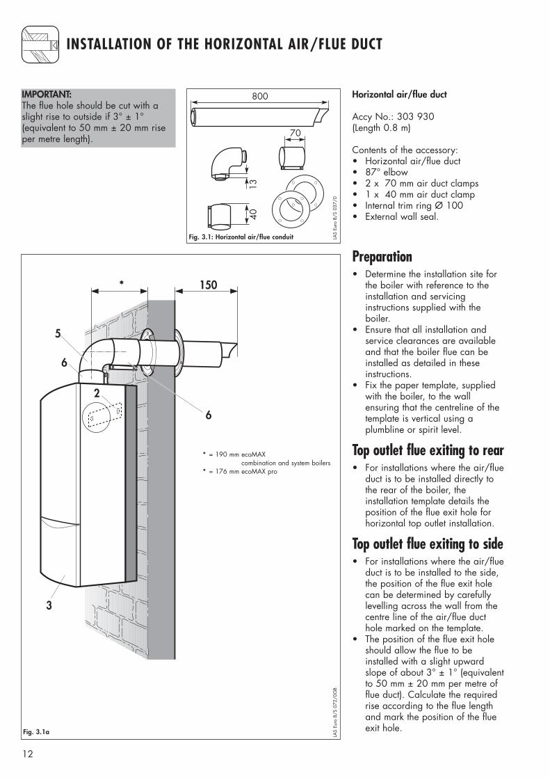
IMPORTANT:The flue hole should be cut with aslight rise to outside if 3° ± 1°(equivalent to 50 mm ± 20 mm riseper metre length).
Preparation• Determine the installation site for
the boiler with reference to theinstallation and servicing instructions supplied with the boiler.
• Ensure that all installation and service clearances are availableand that the boiler flue can beinstalled as detailed in theseinstructions.
• Fix the paper template, suppliedwith the boiler, to the wall ensuring that the centreline of the template is vertical using a plumbline or spirit level.
Top outlet flue exiting to rear• For installations where the air/flue
duct is to be installed directly tothe rear of the boiler, the installation template details theposition of the flue exit hole forhorizontal top outlet installation.
Top outlet flue exiting to side• For installations where the air/flue
duct is to be installed to the side,the position of the flue exit holecan be determined by carefullylevelling across the wall from thecentre line of the air/flue ducthole marked on the template.
• The position of the flue exit holeshould allow the flue to be installed with a slight upwardslope of about 3° ± 1° (equivalentto 50 mm ± 20 mm per metre offlue duct). Calculate the requiredrise according to the flue lengthand mark the position of the flueexit hole.
800
4013
70
LAS
Euro
B/S
037
/05
190 150
6
6
2
3
Fig. 3.1a
LAS
Euro
B/S
072
/0G
B
*
* = 190 mm ecoMAXcombination and system boilers
* = 176 mm ecoMAX pro
13
INSTALLATION OF THE HORIZONTAL AIR/FLUE DUCT (TOP OUTLET)
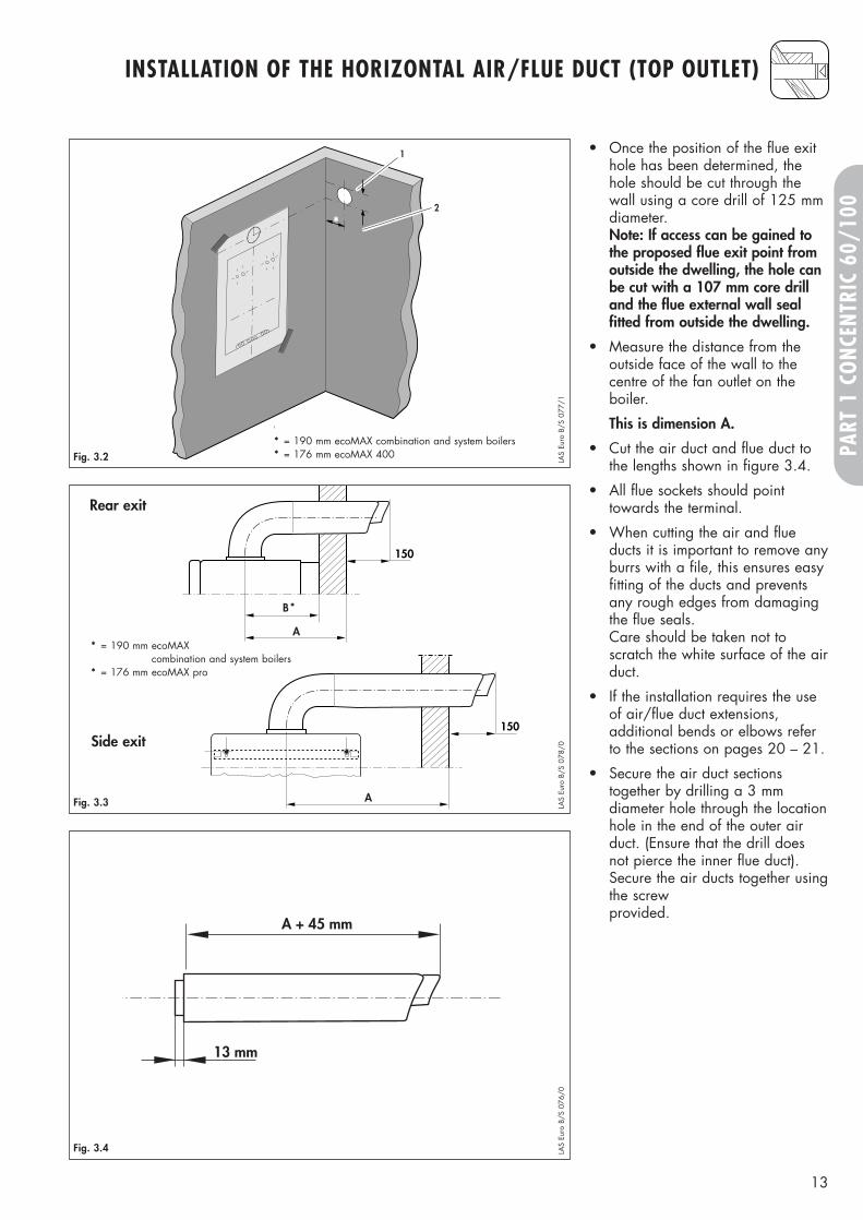
• Once the position of the flue exithole has been determined, thehole should be cut through thewall using a core drill of 125 mmdiameter.Note: If access can be gained tothe proposed flue exit point fromoutside the dwelling, the hole canbe cut with a 107 mm core drilland the flue external wall seal fitted from outside the dwelling.
• Measure the distance from the outside face of the wall to the centre of the fan outlet on the boiler.
This is dimension A.
• Cut the air duct and flue duct tothe lengths shown in figure 3.4.
• All flue sockets should pointtowards the terminal.
• When cutting the air and flueducts it is important to remove anyburrs with a file, this ensures easyfitting of the ducts and preventsany rough edges from damagingthe flue seals.Care should be taken not toscratch the white surface of the airduct.
• If the installation requires the useof air/flue duct extensions, additional bends or elbows referto the sections on pages 20 – 21.
• Secure the air duct sectionstogether by drilling a 3 mmdiameter hole through the locationhole in the end of the outer airduct. (Ensure that the drill doesnot pierce the inner flue duct).Secure the air ducts together usingthe screw provided.
1
2
*
* = 190 mm
Fig. 3.2 LAS
Euro
B/S
077
/1150
A
B
A
150
Fig. 3.3 LAS
Euro
B/S
078
/0
A + 45 mm
13 mm
Fig. 3.4 LAS
Euro
B/S
076
/0
Rear exit
Side exit
PART
1 C
ONC
ENTR
IC 6
0/10
0
*
* = 190 mm ecoMAXcombination and system boilers
* = 176 mm ecoMAX pro
* = 190 mm ecoMAX combination and system boilers* = 176 mm ecoMAX 400
14
INSTALLATION OF THE HORIZONTAL AIR/FLUE DUCT (TOP OUTLET)
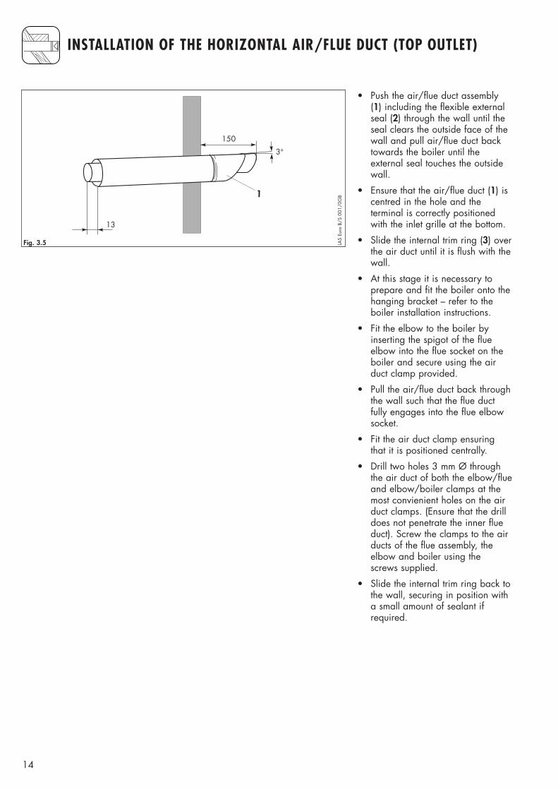
• Push the air/flue duct assembly(1) including the flexible externalseal (2) through the wall until theseal clears the outside face of thewall and pull air/flue duct backtowards the boiler until the external seal touches the outsidewall.
• Ensure that the air/flue duct (1) iscentred in the hole and the terminal is correctly positionedwith the inlet grille at the bottom.
• Slide the internal trim ring (3) overthe air duct until it is flush with thewall.
• At this stage it is necessary to prepare and fit the boiler onto thehanging bracket – refer to the boiler installation instructions.
• Fit the elbow to the boiler by inserting the spigot of the flueelbow into the flue socket on theboiler and secure using the airduct clamp provided.
• Pull the air/flue duct back throughthe wall such that the flue ductfully engages into the flue elbowsocket.
• Fit the air duct clamp ensuringthat it is positioned centrally.
• Drill two holes 3 mm Ø throughthe air duct of both the elbow/flueand elbow/boiler clamps at themost convienient holes on the airduct clamps. (Ensure that the drilldoes not penetrate the inner flueduct). Screw the clamps to the airducts of the flue assembly, theelbow and boiler using the screws supplied.
• Slide the internal trim ring back tothe wall, securing in position witha small amount of sealant if required.
150
13
3°
1
Fig. 3.5 LAS
Euro
B/S
001
/0G
B
15
PART
1 C
ONC
ENTR
IC 6
0/10
0
1530
880
70
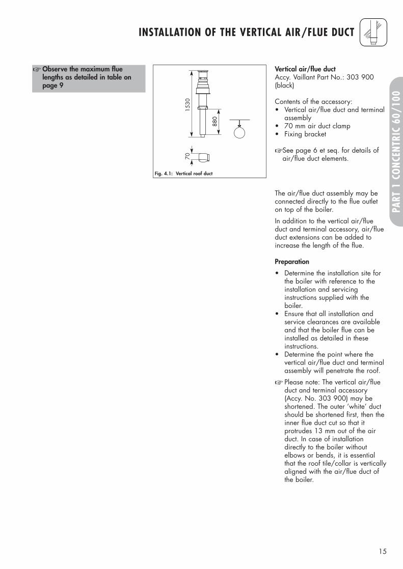
Vertical air/flue duct Accy. Vaillant Part No.: 303 900(black)
Contents of the accessory:• Vertical air/flue duct and terminal
assembly• 70 mm air duct clamp• Fixing bracket
☞ See page 6 et seq. for details ofair/flue duct elements.
☞ Observe the maximum fluelengths as detailed in table onpage 9
Fig. 4.1: Vertical roof duct
The air/flue duct assembly may beconnected directly to the flue outleton top of the boiler.
In addition to the vertical air/flueduct and terminal accessory, air/flueduct extensions can be added toincrease the length of the flue.
Preparation
• Determine the installation site forthe boiler with reference to theinstallation and servicinginstructions supplied with theboiler.
• Ensure that all installation andservice clearances are availableand that the boiler flue can beinstalled as detailed in theseinstructions.
• Determine the point where thevertical air/flue duct and terminalassembly will penetrate the roof.
☞ Please note: The vertical air/flueduct and terminal accessory(Accy. No. 303 900) may beshortened. The outer ‘white’ ductshould be shortened first, then theinner flue duct cut so that itprotrudes 13 mm out of the airduct. In case of installationdirectly to the boiler withoutelbows or bends, it is essentialthat the roof tile/collar is verticallyaligned with the air/flue duct ofthe boiler.
INSTALLATION OF THE VERTICAL AIR/FLUE DUCT
16
INSTALLATION OF THE VERTICAL AIR/FLUE DUCT
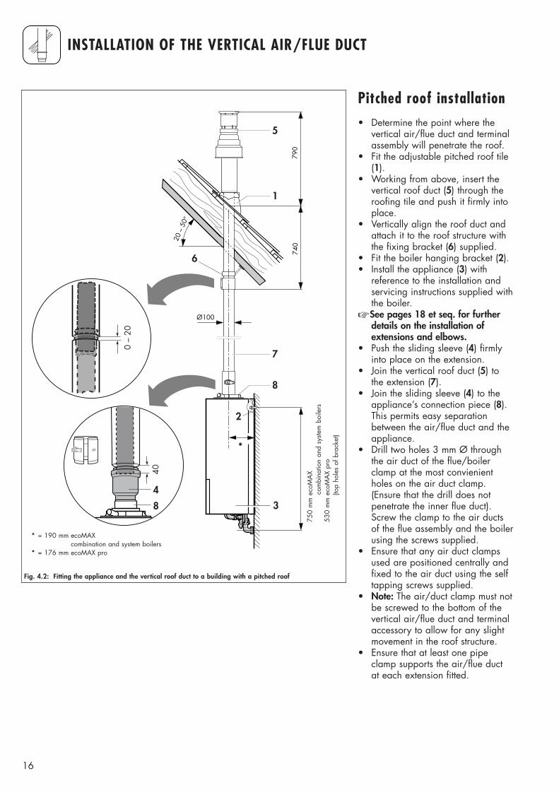
Pitched roof installation• Determine the point where the
vertical air/flue duct and terminalassembly will penetrate the roof.
• Fit the adjustable pitched roof tile(1).
• Working from above, insert thevertical roof duct (5) through theroofing tile and push it firmly intoplace.
• Vertically align the roof duct andattach it to the roof structure withthe fixing bracket (6) supplied.
• Fit the boiler hanging bracket (2).• Install the appliance (3) with
reference to the installation andservicing instructions supplied withthe boiler.
☞ See pages 18 et seq. for furtherdetails on the installation ofextensions and elbows.
• Push the sliding sleeve (4) firmlyinto place on the extension.
• Join the vertical roof duct (5) tothe extension (7).
• Join the sliding sleeve (4) to theappliance’s connection piece (8).This permits easy separationbetween the air/flue duct and theappliance.
• Drill two holes 3 mm Ø throughthe air duct of the flue/boilerclamp at the most convienientholes on the air duct clamp.(Ensure that the drill does notpenetrate the inner flue duct).Screw the clamp to the air ductsof the flue assembly and the boilerusing the screws supplied.
• Ensure that any air duct clampsused are positioned centrally andfixed to the air duct using the selftapping screws supplied.
• Note: The air/duct clamp must notbe screwed to the bottom of thevertical air/flue duct and terminalaccessory to allow for any slightmovement in the roof structure.
• Ensure that at least one pipeclamp supports the air/flue ductat each extension fitted.
750
2
3
790
740
Ø100
20 –
50°
4
5
6
40
8
0 –
20
190
7
8
1
Fig. 4.2: Fitting the appliance and the vertical roof duct to a building with a pitched roof
*
* = 190 mm ecoMAXcombination and system boilers
* = 176 mm ecoMAX pro
750
mm
eco
MA
Xco
mbi
natio
n an
d sy
stem
boi
lers
530
mm
eco
MA
X pr
o (to
p ho
les
of b
rack
et)
17
INSTALLATION OF THE VERTICAL AIR/FLUE DUCT
PART
1 C
ONC
ENTR
IC 6
0/10
0
880
warm roofcold roof
650
Ø100
≥120
2
1
5
6
7
750 4
40
7
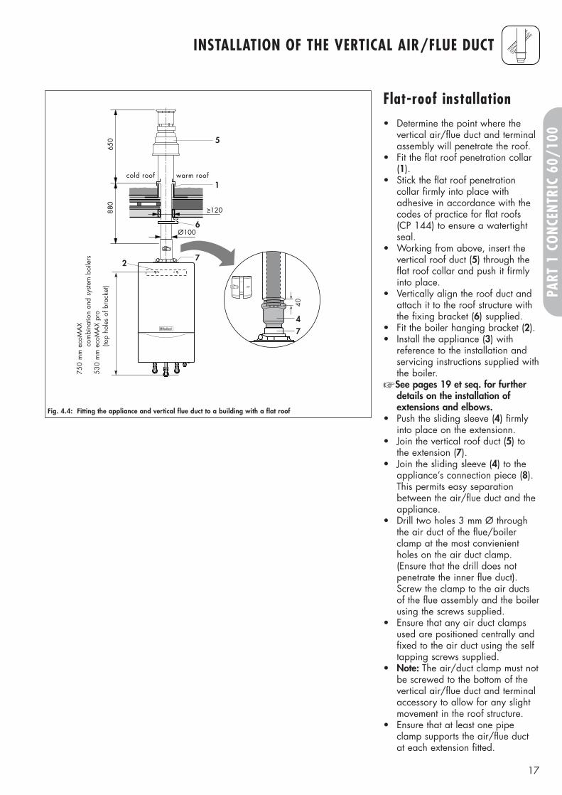
Fig. 4.4: Fitting the appliance and vertical flue duct to a building with a flat roof
Flat-roof installation• Determine the point where the
vertical air/flue duct and terminalassembly will penetrate the roof.
• Fit the flat roof penetration collar(1).
• Stick the flat roof penetrationcollar firmly into place withadhesive in accordance with thecodes of practice for flat roofs (CP 144) to ensure a watertightseal.
• Working from above, insert thevertical roof duct (5) through theflat roof collar and push it firmlyinto place.
• Vertically align the roof duct andattach it to the roof structure withthe fixing bracket (6) supplied.
• Fit the boiler hanging bracket (2).• Install the appliance (3) with
reference to the installation andservicing instructions supplied withthe boiler.
☞ See pages 19 et seq. for furtherdetails on the installation ofextensions and elbows.
• Push the sliding sleeve (4) firmlyinto place on the extensionn.
• Join the vertical roof duct (5) tothe extension (7).
• Join the sliding sleeve (4) to theappliance’s connection piece (8).This permits easy separationbetween the air/flue duct and theappliance.
• Drill two holes 3 mm Ø throughthe air duct of the flue/boilerclamp at the most convienientholes on the air duct clamp.(Ensure that the drill does notpenetrate the inner flue duct).Screw the clamp to the air ductsof the flue assembly and the boilerusing the screws supplied.
• Ensure that any air duct clampsused are positioned centrally andfixed to the air duct using the selftapping screws supplied.
• Note: The air/duct clamp must notbe screwed to the bottom of thevertical air/flue duct and terminalaccessory to allow for any slightmovement in the roof structure.
• Ensure that at least one pipeclamp supports the air/flue ductat each extension fitted.
750
mm
eco
MA
Xco
mbi
natio
n an
d sy
stem
boi
lers
530
mm
eco
MA
X pr
o (to
p ho
les
of b
rack
et)
18
FITTING AIR/FLUE DUCT EXTENSIONS
How to add extensions
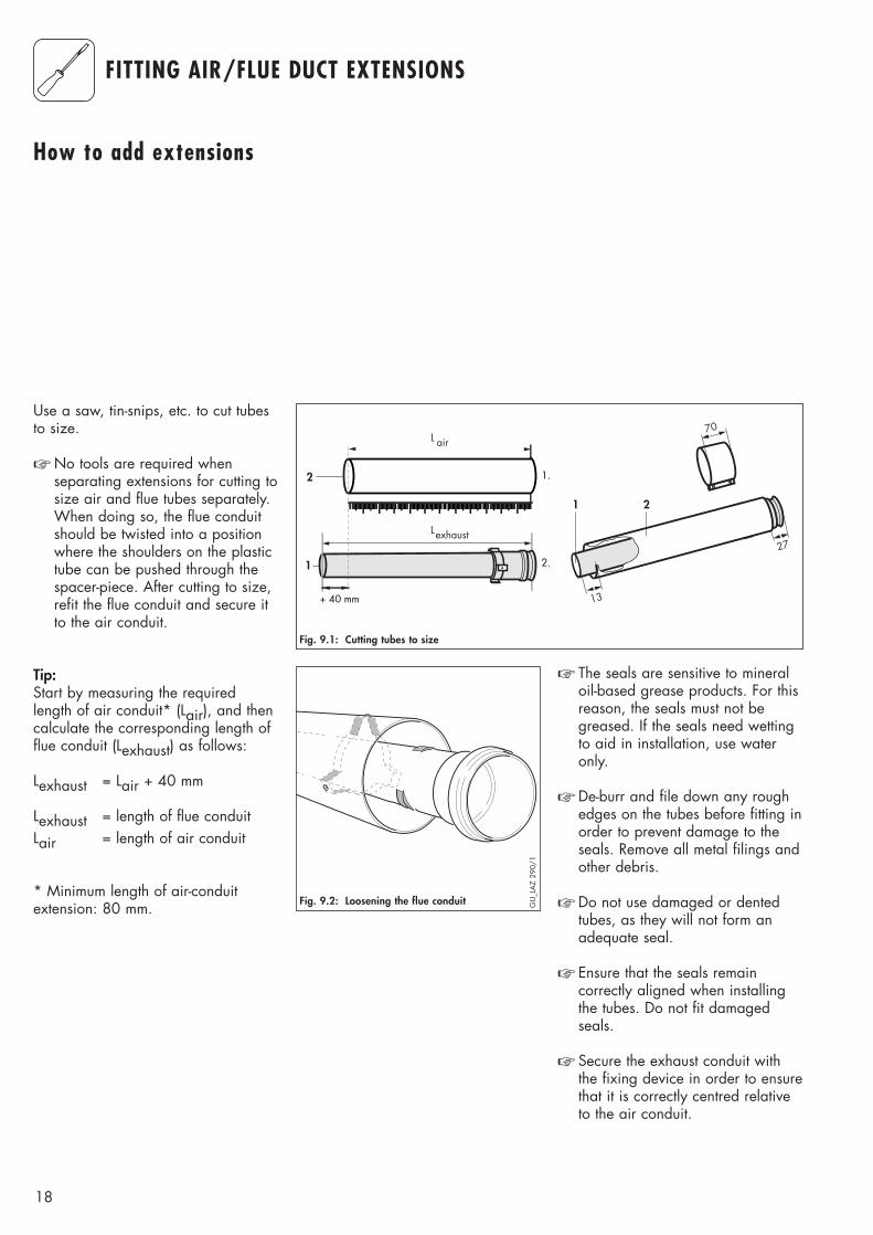
Use a saw, tin-snips, etc. to cut tubesto size.
☞ No tools are required whenseparating extensions for cutting tosize air and flue tubes separately.When doing so, the flue conduitshould be twisted into a positionwhere the shoulders on the plastictube can be pushed through thespacer-piece. After cutting to size,refit the flue conduit and secure itto the air conduit.
Tip:Start by measuring the requiredlength of air conduit* (Lair), and thencalculate the corresponding length offlue conduit (Lexhaust) as follows:
Lexhaust = Lair + 40 mm
Lexhaust = length of flue conduitLair = length of air conduit
* Minimum length of air-conduitextension: 80 mm.
1
2
13
2
70L air
Lexhaust
1.
2.
+ 40 mm
27
1
Fig. 9.1: Cutting tubes to size
☞ The seals are sensitive to mineraloil-based grease products. For thisreason, the seals must not begreased. If the seals need wettingto aid in installation, use wateronly.
☞ De-burr and file down any roughedges on the tubes before fitting inorder to prevent damage to theseals. Remove all metal filings andother debris.
☞ Do not use damaged or dentedtubes, as they will not form anadequate seal.
☞ Ensure that the seals remaincorrectly aligned when installingthe tubes. Do not fit damagedseals.
☞ Secure the exhaust conduit withthe fixing device in order to ensurethat it is correctly centred relativeto the air conduit.
Fig. 9.2: Loosening the flue conduit GU
_LA
Z 29
0/1
19
PART
1 C
ONC
ENTR
IC 6
0/10
0
FITTING AIR/FLUE DUCT EXTENSIONS
Offset Length of[in mm] air conduit
[in mm]
Offset Length of[in mm] air conduit
[in mm]
Offset Length of[in mm] air conduit
[in mm]
690 480695 485700 490705 495710 500715 505720 510725 515730 520735 525740 530745 535750 540755 545760 550765 555770 560775 565780 570785 575790 580795 585800 590
470 260475 265480 270485 275490 280495 285500 290505 295510 300515 305520 310525 315530 320535 325540 330545 335550 340555 345560 350565 355570 360575 365580 370585 375590 380595 385600 390605 395610 400615 405620 410625 415630 420635 425640 430645 435650 440655 445660 450665 455670 460675 465680 470685 475
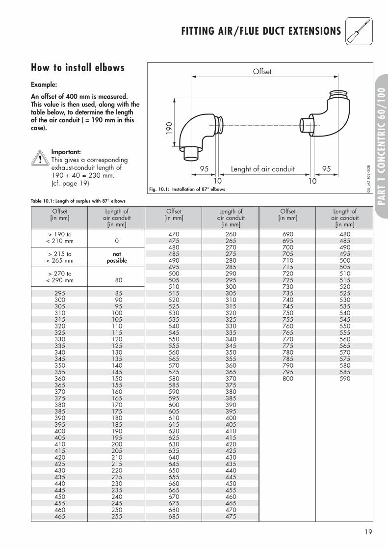
Table 10.1: Length of surplus with 87° elbows
> 190 to< 210 mm 0
> 215 to not< 265 mm possible
> 270 to< 290 mm 80
295 85300 90305 95310 100315 105320 110325 115330 120335 125340 130345 135350 140355 145360 150365 155370 160375 165380 170385 175390 180395 185400 190405 195410 200415 205420 210425 215430 220435 225440 230445 235450 240455 245460 250465 255
How to install elbowsExample:
An offset of 400 mm is measured.This value is then used, along with thetable below, to determine the lengthof the air conduit ( = 190 mm in thiscase).
Important:This gives a correspondingexhaust-conduit length of 190 + 40 = 230 mm. (cf. page 19)
Fig. 10.1: Installation of 87° elbows
190
Offset
Lenght of air conduit95 95
1010
GU
_LA
Z 10
2/2G
B
20
FITTING AIR/FLUE DUCT EXTENSIONS
90 0 21095 0 215
100 0 220
> 105 to not< 155 mm possible
160 86 280165 93 285170 100 290175 107 295180 115 300185 122 305190 129 310195 136 315200 143 320205 150 325210 157 330215 164 335220 171 340225 178 345230 185 350235 192 355240 199 360245 206 365250 214 370255 221 375260 228 380265 235 385270 242 390275 249 395280 256 400285 263 405290 270 410295 277 415300 284 420305 291 425310 298 430315 306 435320 313 440
Offset Length of Height[in mm] air conduit [in mm]
[in mm]
Offset Length of Height[in mm] air conduit [in mm]
[in mm]
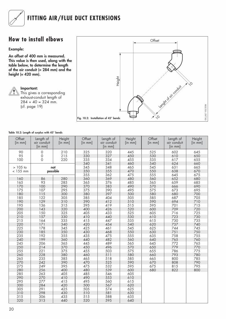
Table 10.2: Length of surplus with 45° bends
Offset Length of Height[in mm] air conduit [in mm]
[in mm]
How to install elbowsExample:
An offset of 400 mm is measured.This value is then used, along with thetable below, to determine the lengthof the air conduit (= 284 mm) and theheight (= 420 mm).
Important:This gives a correspondingexhaust-conduit length of 284 + 40 = 324 mm. (cf. page 19)
GU
_LA
Z 10
3/2G
B
Fig. 10.2: Installation of 45° bends
325 320 445330 327 450335 334 455340 341 460345 348 465350 355 470355 362 475360 369 480365 376 485370 383 490375 390 495380 397 500385 404 505390 412 510395 419 515400 426 520405 433 525410 440 530415 447 535420 454 540425 461 545430 468 550435 475 555440 482 560445 489 565450 496 570455 503 575460 511 580465 518 585470 525 590475 532 595480 539 600485 546 605490 553 610495 560 615500 567 620505 574 625510 581 630515 588 635520 595 640
525 602 645530 610 650535 617 655540 624 660545 631 665550 638 670555 645 675560 652 680565 659 685570 666 690575 673 695580 680 700585 687 705590 694 710595 701 715600 709 720605 716 725610 723 730615 730 735620 737 740625 744 745630 751 750635 758 755640 765 760645 772 765650 779 770655 786 775660 793 780665 800 785670 808 790675 815 795680 822 800
Hei
ght
Offset
Lengh
t of a
ir con
duit 10
10
21
CONTENTS: PART 2 CONCENTRIC 80/125
Page
The air/flue duct must be installed by a suitablyqualified service provider, which is responsiblefor observing the relevant specifications,regulations and standards.
Requirements
Planning the air/flue duct layout
Regulations and standards to be observed 22
Alternative termination accessories available 23Maximum flue lengths 26
Changing the applianceconnection piece
§
28
Installation of the vertical air/flue duct 35
Installation of the horizontal air/flue duct 30
Fitting air/flue duct extensions
Installation of the sliding sleeve
How to add extensions 38How to install elbows 39
29
22
REQUIREMENTS
Regulations andstandards to beobserved
§
☞ Vaillant ecoMAX boilers arecertified as heating boilers with corresponding flue systems according to EC Directive90/396/EEC on gas-fireddevices. This installation manual iscovered by this certification and isreferred to in the design approvaltest certificate.
☞ These instructions should be readin conjunction with the instructionsfor installation and servicing supplied with the boiler.
☞ Ensure also that all legislation,rules, regulations and directivesmentioned in the installationinstructions are observed.
☞ The installation of the boiler andits flue must be carried out by acompetent person who is registered with CORGI (TheCouncil for Registered GasInstallers).
☞ The installation of the boiler andflue must be in accordance withthe Gas Safety (Installation andUse) Regulations 1998 and theBuilding Regulations and BS 5440 Part 1.
☞ The requirements for flue termination detailed in the boilerinstallation instructions must beobserved.
☞ The air/flue duct operates at verylow temperatures therefore noclearance is necessary betweenthe air duct and adjacent services.
☞ Ensure while installation work isbeing carried out that no debrissuch as swarf, filings or fragmentsof mortar are allowed to remainin the air/flue duct.
23
PART
2 C
ONC
ENTR
IC 8
0/12
5
PLANNING THE AIR/FLUE DUCT LAYOUT
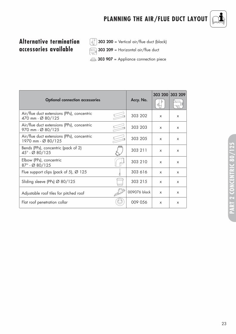
Alternative terminationaccessories available
303 200 = Vertical air/flue duct (black)
303 209 = Horizontal air/flue duct
303 907 = Appliance connection piece
Optional connection accessories Accy. No.303 200
Air/flue duct extensions (PPs), concentric470 mm - Ø 80/125 303 202 x
Air/flue duct extensions (PPs), concentric970 mm - Ø 80/125 303 203 x
Air/flue duct extensions (PPs), concentric1970 mm - Ø 80/125 303 205 x
Bends (PPs), concentric (pack of 2)45° - Ø 80/125 303 211 x
Elbow (PPs), concentric87° - Ø 80/125
303 210 x
Flue support clips (pack of 5), Ø 125 303 616 x
Sliding sleeve (PPs) Ø 80/125 303 215 x
Adjustable roof tiles for pitched roof 009076 black x
Flat roof penetration collar 009 056 x
303 209
x
x
x
x
x
x
x
x
x
24
PLANNING THE AIR/FLUE DUCT LAYOUT
Fig. 1.2: Extensions, Ø 80/125
Fig. 1.4: Flue support clips, Ø 125 or Ø 80
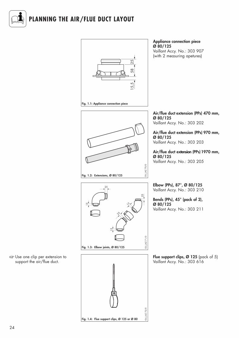
Flue support clips, Ø 125 (pack of 5)Vaillant Accy. No.: 303 616
☞ Use one clip per extension to support the air/flue duct.
15
25
15
25
15
25
Fig. 1.3: Elbow joints, Ø 80/125
Elbow (PPs), 87°, Ø 80/125Vaillant Accy. No.: 303 210
Bends (PPs), 45° (pack of 2), Ø 80/125Vaillant Accy. No.: 303 211
Air/flue duct extension (PPs) 470 mm, Ø 80/125Vaillant Accy. No.: 303 202
Air/flue duct extension (PPs) 970 mm,Ø 80/125Vaillant Accy. No.: 303 203
Air/flue duct extension (PPs) 1970 mm,Ø 80/125 Vaillant Accy. No.: 303 205
GU
_LA
Z 70
/0
GU
_LA
Z 72
/0
GU
_LA
Z 71
/0
5825
15,5
Fig. 1.1: Appliance connection piece
Appliance connection pieceØ 80/125Vaillant Accy. No.: 303 907(with 2 measuring apetures)
25
PART
2 C
ONC
ENTR
IC 8
0/12
5
PLANNING THE AIR/FLUE DUCT LAYOUT
Fig. 1.6: Adjustable roof tile for pitched roof
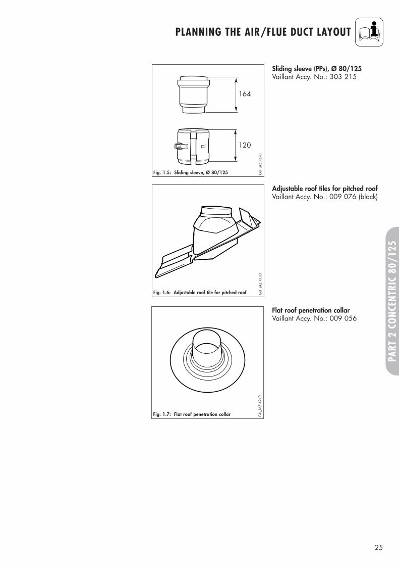
Adjustable roof tiles for pitched roofVaillant Accy. No.: 009 076 (black)
GU
_LA
Z 41
/0
164
120
Fig. 1.5: Sliding sleeve, Ø 80/125
Sliding sleeve (PPs), Ø 80/125 Vaillant Accy. No.: 303 215
GU
_LA
Z 76
/0
Fig. 1.7: Flat roof penetration collar GU
_LA
Z 42
/0
Flat roof penetration collarVaillant Accy. No.: 009 056
26
PLANNING THE AIR/FLUE DUCT LAYOUT
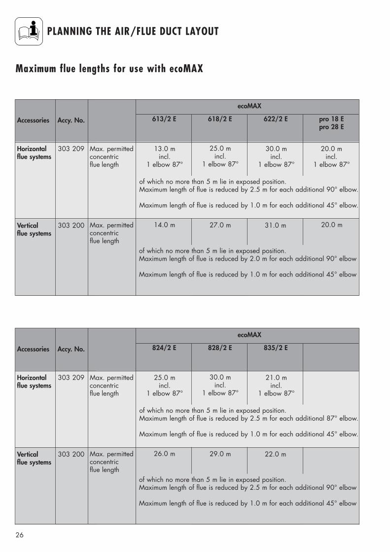
Maximum flue lengths for use with ecoMAX
Accessories Accy. No.
Vertical flue systems
303 200 Max. permitted concentric flue length
Horizontal flue systems
303 209 Max. permittedconcentricflue length
14.0 m
13.0 mincl.
1 elbow 87°
31.0 m 20.0 m
30.0 mincl.
1 elbow 87°
20.0 mincl.
1 elbow 87°
27.0 m
25.0 mincl.
1 elbow 87°
613/2 E 618/2 E 622/2 E pro 18 Epro 28 E
ecoMAX
of which no more than 5 m lie in exposed position.Maximum length of flue is reduced by 2.5 m for each additional 90° elbow.
Maximum length of flue is reduced by 1.0 m for each additional 45° elbow.
of which no more than 5 m lie in exposed position.Maximum length of flue is reduced by 2.0 m for each additional 90° elbow
Maximum length of flue is reduced by 1.0 m for each additional 45° elbow
Accessories Accy. No.
Vertical flue systems
303 200 Max. permitted concentric flue length
Horizontal flue systems
303 209 Max. permittedconcentricflue length
26.0 m
25.0 mincl.
1 elbow 87°
22.0 m
21.0 mincl.
1 elbow 87°
29.0 m
30.0 mincl.
1 elbow 87°
824/2 E 828/2 E 835/2 E
ecoMAX
of which no more than 5 m lie in exposed position.Maximum length of flue is reduced by 2.5 m for each additional 87° elbow.
Maximum length of flue is reduced by 1.0 m for each additional 45° elbow.
of which no more than 5 m lie in exposed position.Maximum length of flue is reduced by 2.5 m for each additional 90° elbow
Maximum length of flue is reduced by 1.0 m for each additional 45° elbow
27
PART
2 C
ONC
ENTR
IC 8
0/12
5
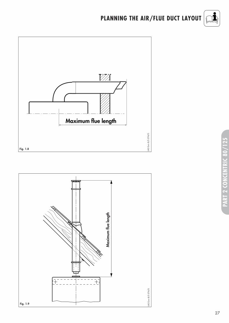
PLANNING THE AIR/FLUE DUCT LAYOUT
Maximum flue length
Max
imum
flue
leng
th
LAS
Euro
B/S
074
/0LA
S Eu
ro B
/S 0
74/0
Fig. 1.9
Fig. 1.8
28
CHANGING THE APPLIANCE CONNECTION-PIECE
1
2
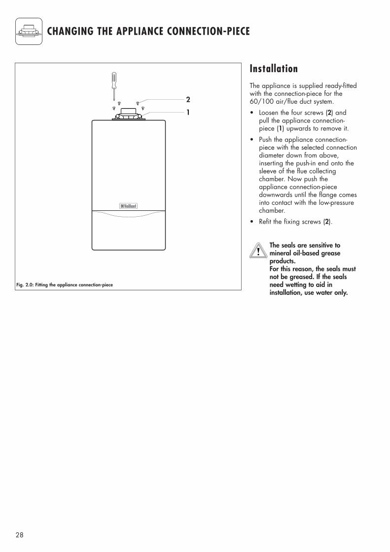
Fig. 2.0: Fitting the appliance connection-piece
InstallationThe appliance is supplied ready-fittedwith the connection-piece for the60/100 air/flue duct system.
• Loosen the four screws (2) andpull the appliance connection-piece (1) upwards to remove it.
• Push the appliance connection-piece with the selected connectiondiameter down from above,inserting the push-in end onto thesleeve of the flue collectingchamber. Now push theappliance connection-piecedownwards until the flange comesinto contact with the low-pressurechamber.
• Refit the fixing screws (2).
The seals are sensitive tomineral oil-based greaseproducts. For this reason, the seals mustnot be greased. If the sealsneed wetting to aid ininstallation, use water only.
29
PART
2 C
ONC
ENTR
IC 8
0/12
5
INSTALLATION OF THE SLIDING SLEEVE
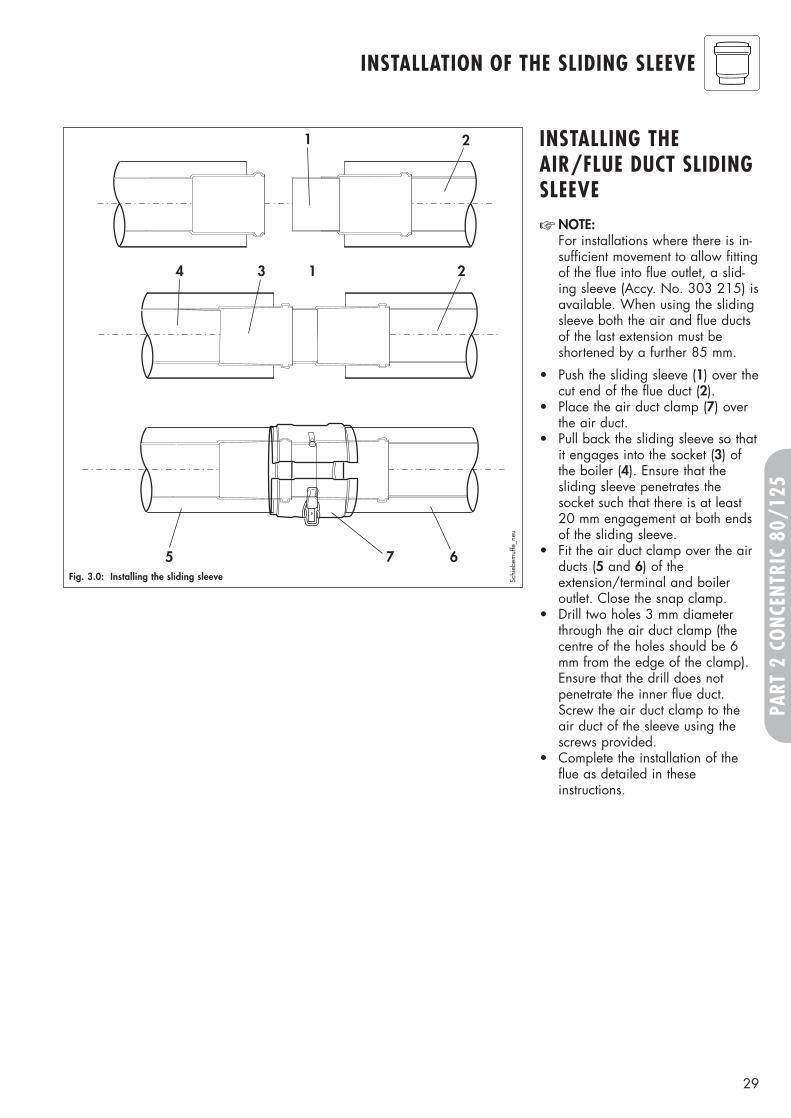
Fig. 3.0: Installing the sliding sleeve
1 2
3 1 24
5 67
Schi
ebem
uffe
_neu
INSTALLING THEAIR/FLUE DUCT SLIDINGSLEEVE☞ NOTE:
For installations where there is in-sufficient movement to allow fittingof the flue into flue outlet, a slid-ing sleeve (Accy. No. 303 215) isavailable. When using the slidingsleeve both the air and flue ductsof the last extension must beshortened by a further 85 mm.
• Push the sliding sleeve (1) over thecut end of the flue duct (2).
• Place the air duct clamp (7) overthe air duct.
• Pull back the sliding sleeve so thatit engages into the socket (3) ofthe boiler (4). Ensure that thesliding sleeve penetrates thesocket such that there is at least20 mm engagement at both endsof the sliding sleeve.
• Fit the air duct clamp over the airducts (5 and 6) of theextension/terminal and boileroutlet. Close the snap clamp.
• Drill two holes 3 mm diameterthrough the air duct clamp (thecentre of the holes should be 6mm from the edge of the clamp).Ensure that the drill does notpenetrate the inner flue duct.Screw the air duct clamp to theair duct of the sleeve using thescrews provided.
• Complete the installation of theflue as detailed in theseinstructions.
30
INSTALLATION OF THE HORIZONTAL AIR/FLUE DUCT
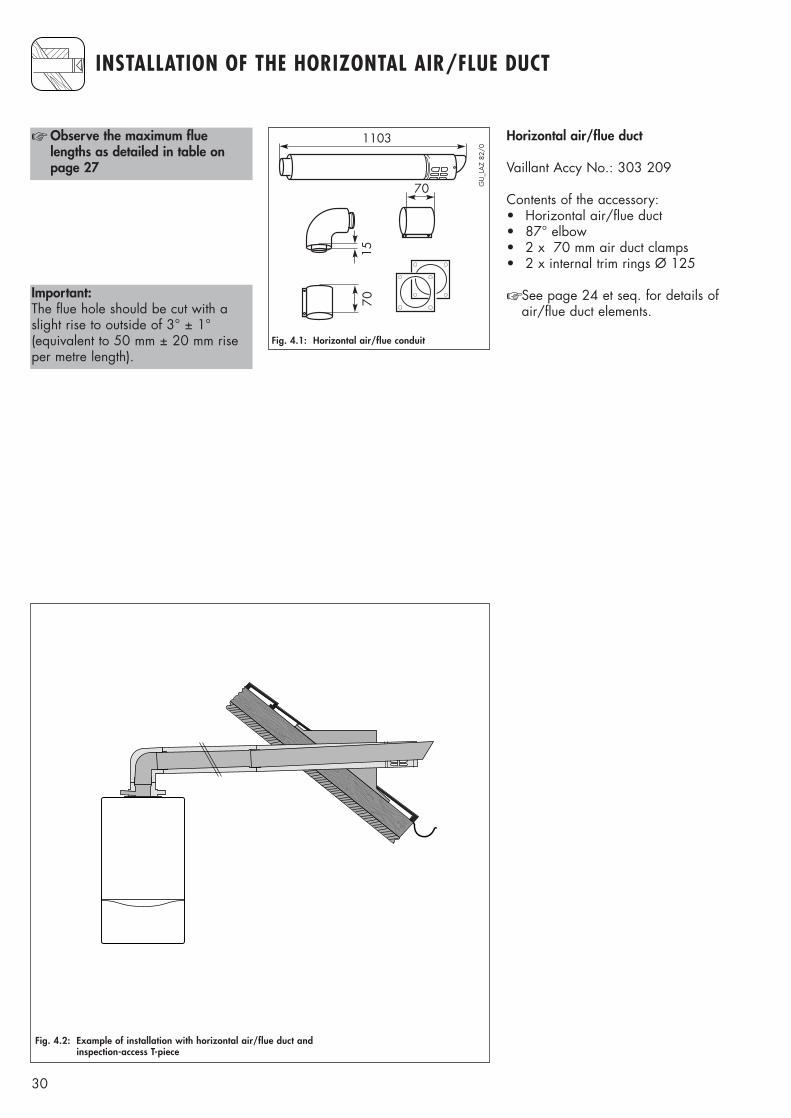
☞ Observe the maximum fluelengths as detailed in table onpage 27
70
1103
70
15
Horizontal air/flue duct
Vaillant Accy No.: 303 209
Contents of the accessory:• Horizontal air/flue duct• 87° elbow• 2 x 70 mm air duct clamps • 2 x internal trim rings Ø 125
☞ See page 24 et seq. for details ofair/flue duct elements.
Fig. 4.1: Horizontal air/flue conduit
GU
_LA
Z 82
/0
Important:The flue hole should be cut with aslight rise to outside of 3° ± 1°(equivalent to 50 mm ± 20 mm riseper metre length).
Fig. 4.2: Example of installation with horizontal air/flue duct andinspection-access T-piece
31
PART
2 C
ONC
ENTR
IC 8
0/12
5
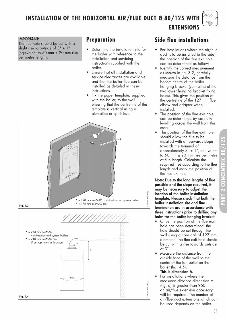
IMPORTANT:The flue hole should be cut with aslight rise to outside of 3° ± 1°(equivalent to 50 mm ± 20 mm riseper metre length).
Side flue installations• For installations where the air/flue
duct is to be installed to the side,the position of the flue exit holecan be determined as follows:
• Identify the correct measurementas shown in fig. 3.2, carefullymeasure the distance from the bottom centre of the boiler hanging bracket (centreline of thetwo lower hanging bracket fixingholes). This gives the position ofthe centreline of the 127 mm flueelbow and adaptor when installed.
• The position of the flue exit holecan be determined by carefullylevelling across the wall from thismark.
• The position of the flue exit holeshould allow the flue to be installed with an upwards slopetowards the terminal of approximately 3° ± 1°, equivalentto 50 mm ± 20 mm rise per metreof flue length. Calculate therequired rise according to the fluelength and mark the position ofthe flue exithole.
Note: Due to the long lengths of fluepossible and the slope required, itmay be necessary to adjust the location of the boiler installation template. Please check that both theboiler installation site and flue termination are in accordance withthese instructions prior to drilling anyholes for the boiler hanging bracket.• Once the position of the flue exit
hole has been determined, thehole should be cut through thewall using a core drill of 127 mmdiameter. The flue exit hole shouldbe cut with a rise towards outsideof 3°.
• Measure the distance from the outside face of the wall to the centre of the fan outlet on the boiler (fig. 4.5).This is dimension A.
• For installations where the measured distance dimension A(fig. 6) is greater than 960 mm,an air/flue extension accessorywill be required. The number ofair/flue duct extensions which canbe used depends on the boiler.
Preparation• Determine the installation site for
the boiler with reference to theinstallation and servicing instructions supplied with the boiler.
• Ensure that all installation and service clearances are availableand that the boiler flue can beinstalled as detailed in theseinstructions.
• Fix the paper template, suppliedwith the boiler, to the wall ensuring that the centreline of thetemplate is vertical using a plumbline or spirit level.
1
2
*
* = 190 mm
Fig. 4.3 LAS
Euro
B/S
077
/1
253
Fig. 4.4 LAS
Euro
B/S
083
/1
INSTALLATION OF THE HORIZONTAL AIR/FLUE DUCT Ø 80/125 WITHEXTENSIONS
* = 190 mm ecoMAX combination and system boilers* = 176 mm ecoMAX pro
*
* = 253 mm ecoMAXcombination and system boilers
* = 210 mm ecoMAX pro(from top holes on bracket)
32
INSTALLATION OF THE HORIZONTAL AIR/FLUE DUCT Ø 80/125 WITHEXTENSIONS
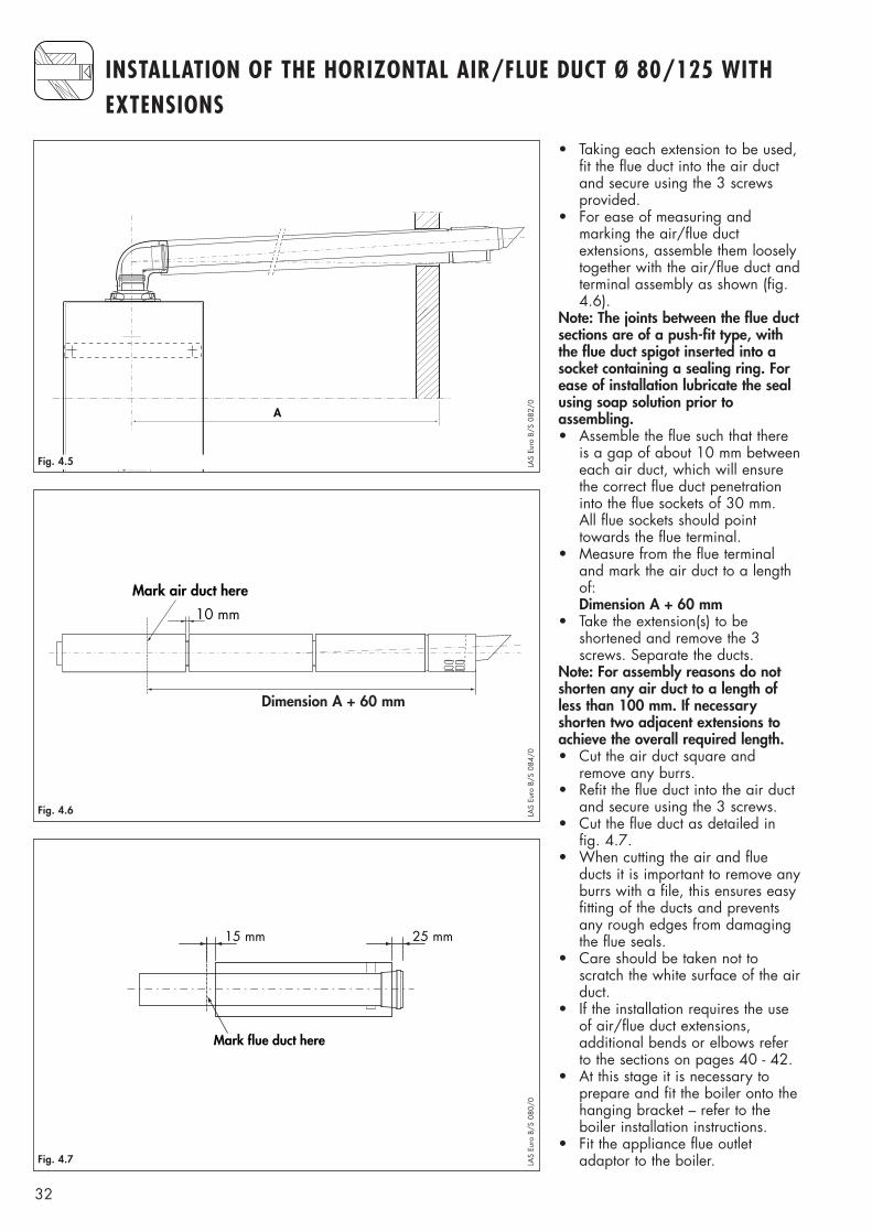
• Taking each extension to be used,fit the flue duct into the air ductand secure using the 3 screwsprovided.
• For ease of measuring and marking the air/flue duct extensions, assemble them looselytogether with the air/flue duct andterminal assembly as shown (fig.4.6).
Note: The joints between the flue ductsections are of a push-fit type, withthe flue duct spigot inserted into asocket containing a sealing ring. Forease of installation lubricate the sealusing soap solution prior to assembling.• Assemble the flue such that there
is a gap of about 10 mm betweeneach air duct, which will ensurethe correct flue duct penetrationinto the flue sockets of 30 mm. All flue sockets should pointtowards the flue terminal.
• Measure from the flue terminaland mark the air duct to a lengthof:Dimension A + 60 mm
• Take the extension(s) to be shortened and remove the 3 screws. Separate the ducts.
Note: For assembly reasons do notshorten any air duct to a length ofless than 100 mm. If necessary shorten two adjacent extensions toachieve the overall required length.• Cut the air duct square and
remove any burrs.• Refit the flue duct into the air duct
and secure using the 3 screws.• Cut the flue duct as detailed in
fig. 4.7.• When cutting the air and flue
ducts it is important to remove anyburrs with a file, this ensures easyfitting of the ducts and preventsany rough edges from damagingthe flue seals.
• Care should be taken not toscratch the white surface of the airduct.
• If the installation requires the useof air/flue duct extensions, additional bends or elbows referto the sections on pages 40 - 42.
• At this stage it is necessary toprepare and fit the boiler onto thehanging bracket – refer to theboiler installation instructions.
• Fit the appliance flue outletadaptor to the boiler.
A
Fig. 4.5 LAS
Euro
B/S
082
/0
10 mm
Mark air duct here
Dimension A + 20 mm
Fig. 4.6 LAS
Euro
B/S
084
/0
25 mm
Mark flue duct here
15 mm
Fig. 4.7 LAS
Euro
B/S
080
/0
Dimension A + 60 mm
33
PART
2 C
ONC
ENTR
IC 8
0/12
5
220
15
3°
1
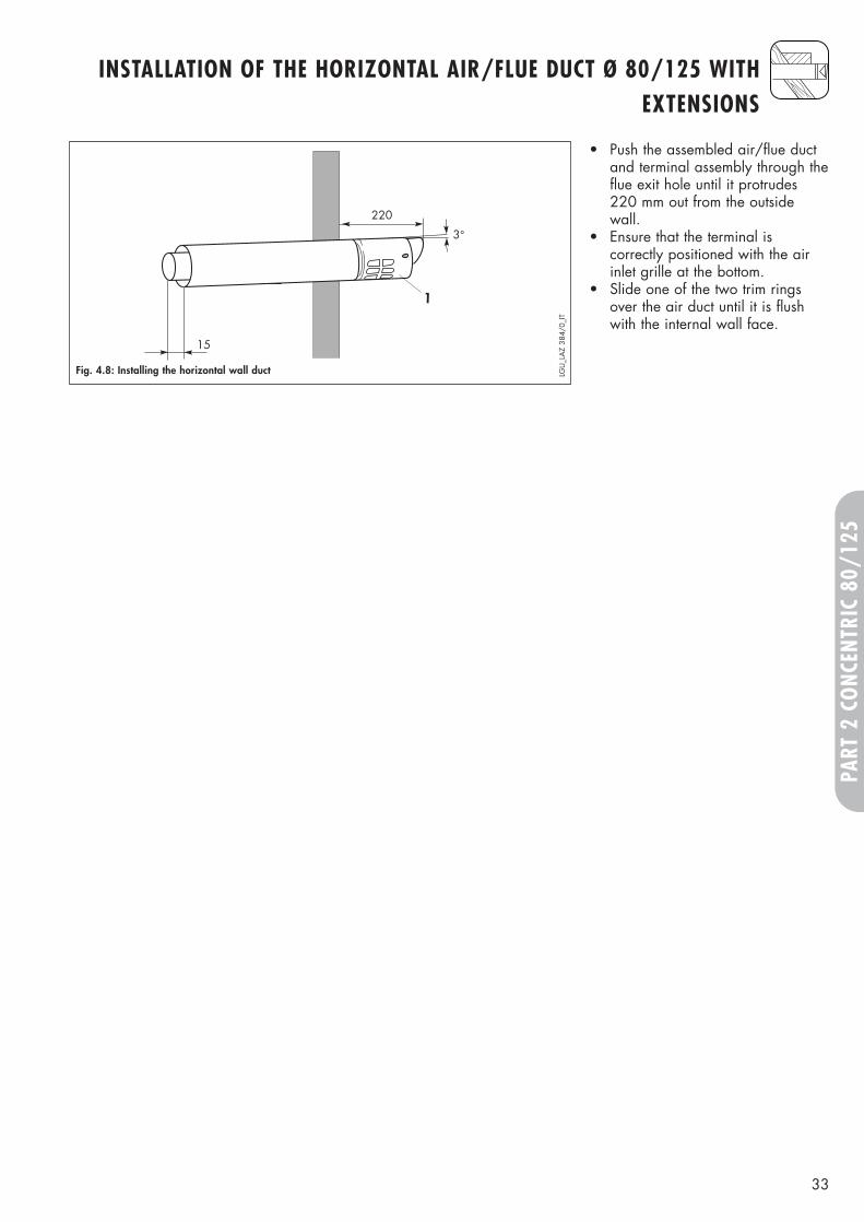
Fig. 4.8: Installing the horizontal wall duct LGU
_LA
Z 38
4/0_
IT
• Push the assembled air/flue ductand terminal assembly through theflue exit hole until it protrudes 220 mm out from the outsidewall.
• Ensure that the terminal is correctly positioned with the airinlet grille at the bottom.
• Slide one of the two trim ringsover the air duct until it is flushwith the internal wall face.
INSTALLATION OF THE HORIZONTAL AIR/FLUE DUCT Ø 80/125 WITHEXTENSIONS
34
INSTALLATION OF THE HORIZONTAL AIR/FLUE DUCT AND TERMINALACCESSORY (80/125 Ø)
8
82 - 84
253
7
4
2
3
6
750
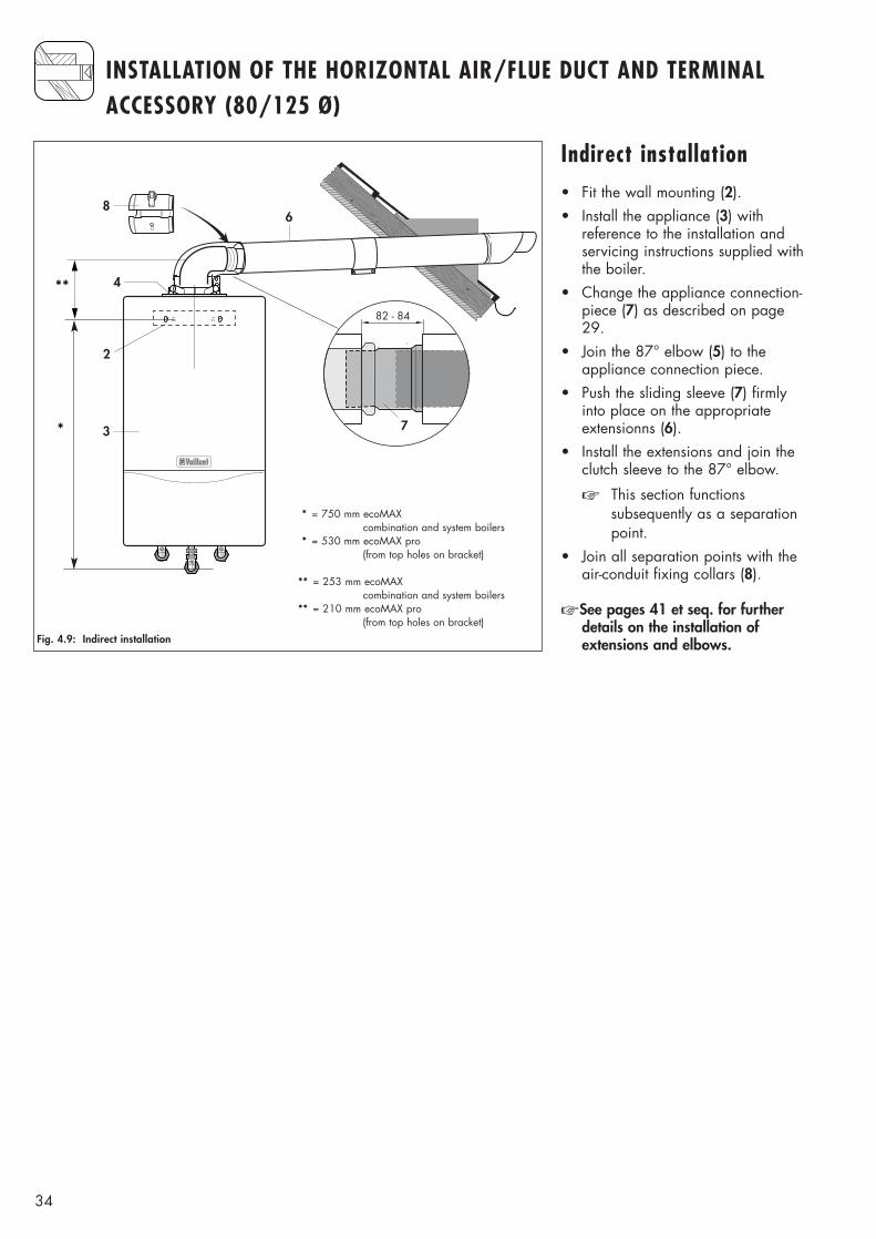
Fig. 4.9: Indirect installation
Indirect installation• Fit the wall mounting (2).• Install the appliance (3) with
reference to the installation andservicing instructions supplied withthe boiler.
• Change the appliance connection-piece (7) as described on page29.
• Join the 87° elbow (5) to theappliance connection piece.
• Push the sliding sleeve (7) firmlyinto place on the appropriateextensionns (6).
• Install the extensions and join theclutch sleeve to the 87° elbow.
☞ This section functionssubsequently as a separationpoint.
• Join all separation points with theair-conduit fixing collars (8).
☞ See pages 41 et seq. for furtherdetails on the installation ofextensions and elbows.
**
*
* = 750 mm ecoMAXcombination and system boilers
* = 530 mm ecoMAX pro(from top holes on bracket)
** = 253 mm ecoMAXcombination and system boilers
** = 210 mm ecoMAX pro(from top holes on bracket)
35
PART
2 C
ONC
ENTR
IC 8
0/12
5
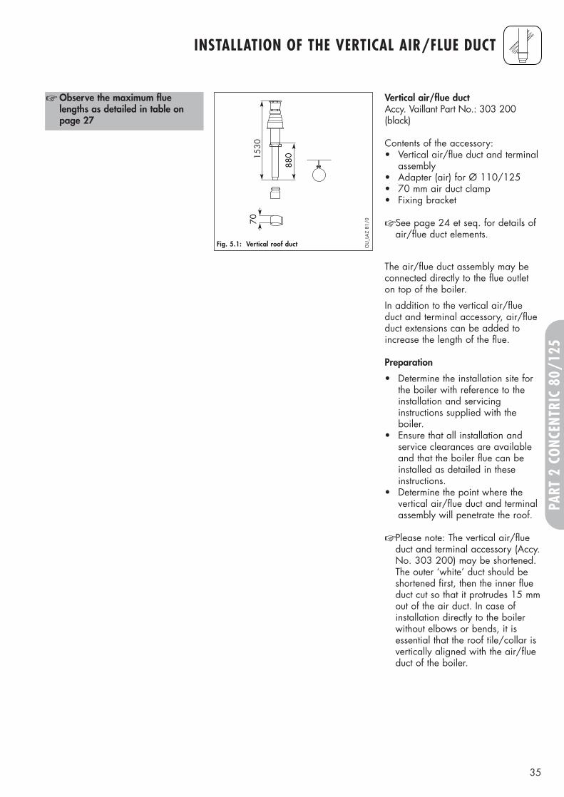
1530
880
70
Vertical air/flue duct Accy. Vaillant Part No.: 303 200(black)
Contents of the accessory:• Vertical air/flue duct and terminal
assembly• Adapter (air) for Ø 110/125• 70 mm air duct clamp• Fixing bracket
☞ See page 24 et seq. for details ofair/flue duct elements.
☞ Observe the maximum fluelengths as detailed in table onpage 27
Fig. 5.1: Vertical roof duct GU
_LA
Z 81
/0
The air/flue duct assembly may beconnected directly to the flue outleton top of the boiler.
In addition to the vertical air/flueduct and terminal accessory, air/flueduct extensions can be added toincrease the length of the flue.
Preparation
• Determine the installation site forthe boiler with reference to theinstallation and servicinginstructions supplied with theboiler.
• Ensure that all installation andservice clearances are availableand that the boiler flue can beinstalled as detailed in theseinstructions.
• Determine the point where thevertical air/flue duct and terminalassembly will penetrate the roof.
☞ Please note: The vertical air/flueduct and terminal accessory (Accy.No. 303 200) may be shortened.The outer ‘white’ duct should beshortened first, then the inner flueduct cut so that it protrudes 15 mmout of the air duct. In case ofinstallation directly to the boilerwithout elbows or bends, it isessential that the roof tile/collar isvertically aligned with the air/flueduct of the boiler.
INSTALLATION OF THE VERTICAL AIR/FLUE DUCT
36
INSTALLATION OF THE VERTICAL AIR/FLUE DUCT
750
2
3
790
740
Ø125
20 –
50°
4
5
6
40
10
8
190
7
1
8
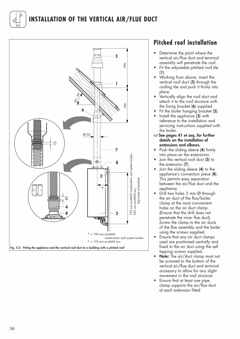
Fig. 5.2: Fitting the appliance and the vertical roof duct to a building with a pitched roof
Pitched roof installation• Determine the point where the
vertical air/flue duct and terminalassembly will penetrate the roof.
• Fit the adjustable pitched roof tile(1).
• Working from above, insert thevertical roof duct (5) through theroofing tile and push it firmly intoplace.
• Vertically align the roof duct andattach it to the roof structure withthe fixing bracket (6) supplied.
• Fit the boiler hanging bracket (2).• Install the appliance (3) with
reference to the installation andservicing instructions supplied withthe boiler.
☞ See pages 41 et seq. for furtherdetails on the installation ofextensions and elbows.
• Push the sliding sleeve (4) firmlyinto place on the extensionn.
• Join the vertical roof duct (5) tothe extension (7).
• Join the sliding sleeve (4) to theappliance’s connection piece (8).This permits easy separationbetween the air/flue duct and theappliance.
• Drill two holes 3 mm Ø throughthe air duct of the flue/boilerclamp at the most convienientholes on the air duct clamp.(Ensure that the drill does notpenetrate the inner flue duct).Screw the clamp to the air ductsof the flue assembly and the boilerusing the screws supplied.
• Ensure that any air duct clampsused are positioned centrally andfixed to the air duct using the selftapping screws supplied.
• Note: The air/duct clamp must notbe screwed to the bottom of thevertical air/flue duct and terminalaccessory to allow for any slightmovement in the roof structure.
• Ensure that at least one pipeclamp supports the air/flue ductat each extension fitted.
*
* = 190 mm ecoMAXcombination and system boilers
* = 176 mm ecoMAX pro
750
mm
eco
MA
X co
mbi
natio
n an
d sy
stem
boi
lers
530
mm
eco
MA
X pr
o(to
p ho
les
of b
rack
et)
37
PART
2 C
ONC
ENTR
IC 8
0/12
5
INSTALLATION OF THE VERTICAL AIR/FLUE DUCT
880
warm roofcold roof
650
Ø125
≥120
2
1
5
6
7
750 4
40
7
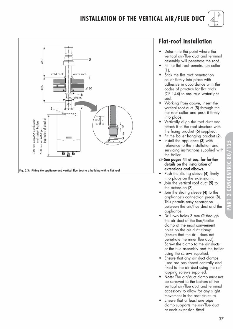
Fig. 5.3: Fitting the appliance and vertical flue duct to a building with a flat roof
Flat-roof installation• Determine the point where the
vertical air/flue duct and terminalassembly will penetrate the roof.
• Fit the flat roof penetration collar(1).
• Stick the flat roof penetrationcollar firmly into place withadhesive in accordance with thecodes of practice for flat roofs (CP 144) to ensure a watertightseal.
• Working from above, insert thevertical roof duct (5) through theflat roof collar and push it firmlyinto place.
• Vertically align the roof duct andattach it to the roof structure withthe fixing bracket (6) supplied.
• Fit the boiler hanging bracket (2).• Install the appliance (3) with
reference to the installation andservicing instructions supplied withthe boiler.
☞ See pages 41 et seq. for furtherdetails on the installation ofextensions and elbows.
• Push the sliding sleeve (4) firmlyinto place on the extensionn.
• Join the vertical roof duct (5) tothe extension (7).
• Join the sliding sleeve (4) to theappliance’s connection piece (8).This permits easy separationbetween the air/flue duct and theappliance.
• Drill two holes 3 mm Ø throughthe air duct of the flue/boilerclamp at the most convienientholes on the air duct clamp.(Ensure that the drill does notpenetrate the inner flue duct).Screw the clamp to the air ductsof the flue assembly and the boilerusing the screws supplied.
• Ensure that any air duct clampsused are positioned centrally andfixed to the air duct using the selftapping screws supplied.
• Note: The air/duct clamp must notbe screwed to the bottom of thevertical air/flue duct and terminalaccessory to allow for any slightmovement in the roof structure.
• Ensure that at least one pipeclamp supports the air/flue ductat each extension fitted.
750
mm
eco
MA
X co
mbi
natin
and
syste
m b
oile
rs53
0 m
m e
coM
AX
pro
(top
hole
s of
bra
cket
)
38
FITTING AIR/FLUE DUCT EXTENSIONS
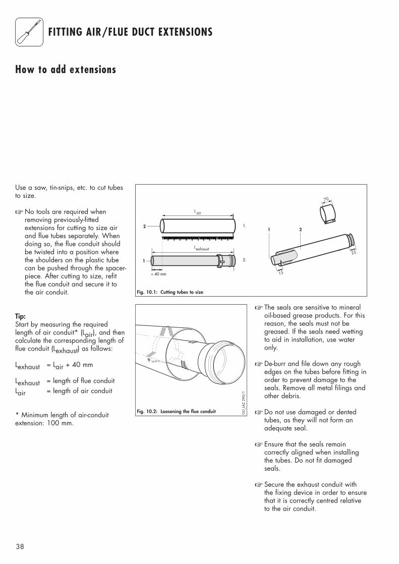
How to add extensions
Use a saw, tin-snips, etc. to cut tubesto size.
☞ No tools are required whenremoving previously-fittedextensions for cutting to size airand flue tubes separately. Whendoing so, the flue conduit shouldbe twisted into a position wherethe shoulders on the plastic tubecan be pushed through the spacer-piece. After cutting to size, refitthe flue conduit and secure it tothe air conduit.
Tip:Start by measuring the requiredlength of air conduit* (Lair), and thencalculate the corresponding length offlue conduit (Lexhaust) as follows:
Lexhaust = Lair + 40 mm
Lexhaust = length of flue conduitLair = length of air conduit
* Minimum length of air-conduitextension: 100 mm.
1
2
15
1 2
70
L air
Lexhaust
1.
2.
+ 40 mm
25
Fig. 10.1: Cutting tubes to size
☞ The seals are sensitive to mineraloil-based grease products. For thisreason, the seals must not begreased. If the seals need wettingto aid in installation, use wateronly.
☞ De-burr and file down any roughedges on the tubes before fitting inorder to prevent damage to theseals. Remove all metal filings andother debris.
☞ Do not use damaged or dentedtubes, as they will not form anadequate seal.
☞ Ensure that the seals remaincorrectly aligned when installingthe tubes. Do not fit damagedseals.
☞ Secure the exhaust conduit withthe fixing device in order to ensurethat it is correctly centred relativeto the air conduit.
Fig. 10.2: Loosening the flue conduit GU
_LA
Z 29
0/1
39
PART
2 C
ONC
ENTR
IC 8
0/12
5
FITTING AIR/FLUE DUCT EXTENSIONS
Offset Length of[in mm] air conduit
[in mm]
Offset Length of[in mm] air conduit
[in mm]
Offset Length of[in mm] air conduit
[in mm]
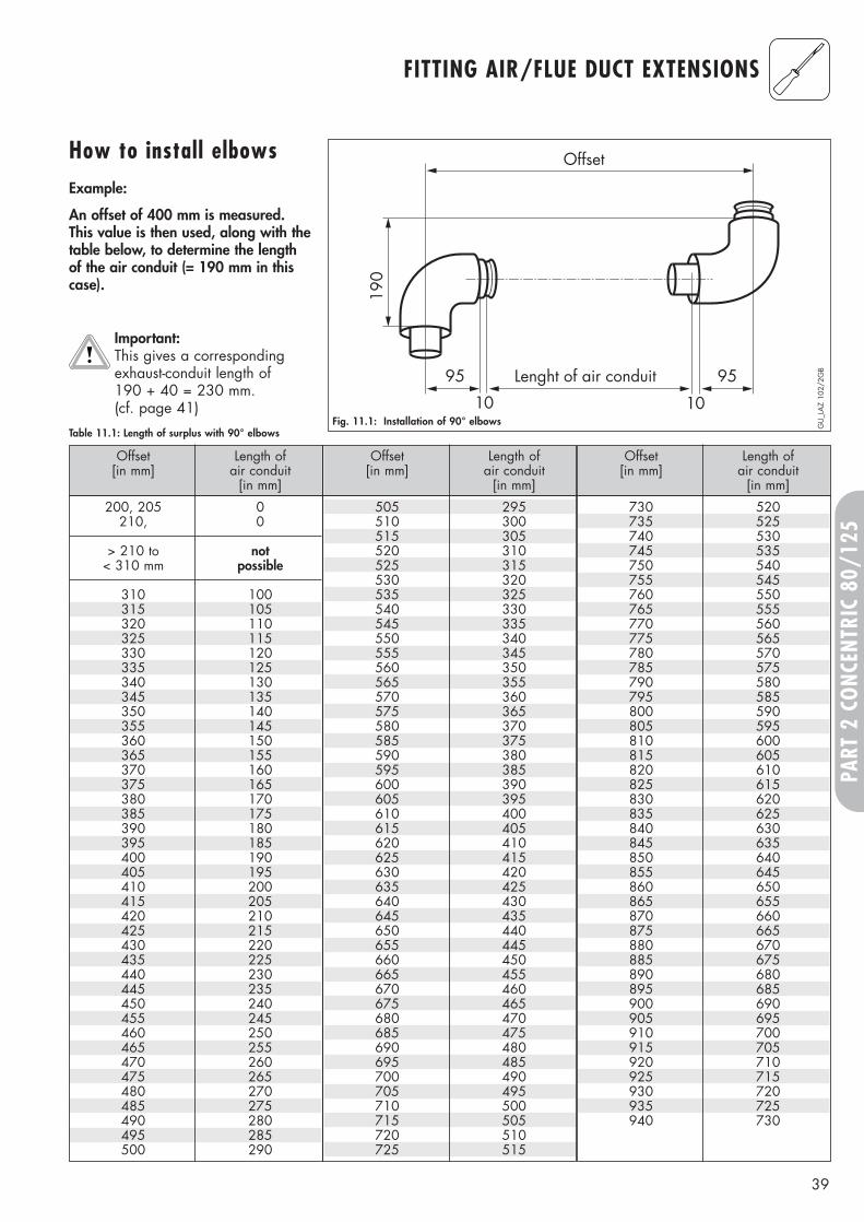
730 520735 525740 530745 535750 540755 545760 550765 555770 560775 565780 570785 575790 580795 585800 590805 595810 600815 605820 610825 615830 620835 625840 630845 635850 640855 645860 650865 655870 660875 665880 670885 675890 680895 685900 690905 695910 700915 705920 710925 715930 720935 725940 730
505 295510 300515 305520 310525 315530 320535 325540 330545 335550 340555 345560 350565 355570 360575 365580 370585 375590 380595 385600 390605 395610 400615 405620 410625 415630 420635 425640 430645 435650 440655 445660 450665 455670 460675 465680 470685 475690 480695 485700 490705 495710 500715 505720 510725 515
Table 11.1: Length of surplus with 90° elbows
200, 205 0210, 0
> 210 to not< 310 mm possible
310 100315 105320 110325 115330 120335 125340 130345 135350 140355 145360 150365 155370 160375 165380 170385 175390 180395 185400 190405 195410 200415 205420 210425 215430 220435 225440 230445 235450 240455 245460 250465 255470 260475 265480 270485 275490 280495 285500 290
How to install elbowsExample:
An offset of 400 mm is measured.This value is then used, along with thetable below, to determine the lengthof the air conduit (= 190 mm in thiscase).
Important:This gives a correspondingexhaust-conduit length of 190 + 40 = 230 mm. (cf. page 41)
190
Offset
Lenght of air conduit95 95
1010Fig. 11.1: Installation of 90° elbows G
U_L
AZ
102/
2GB
40
90 0 21095 0 215
100 0 220
> 100 to not< 170 mm possible
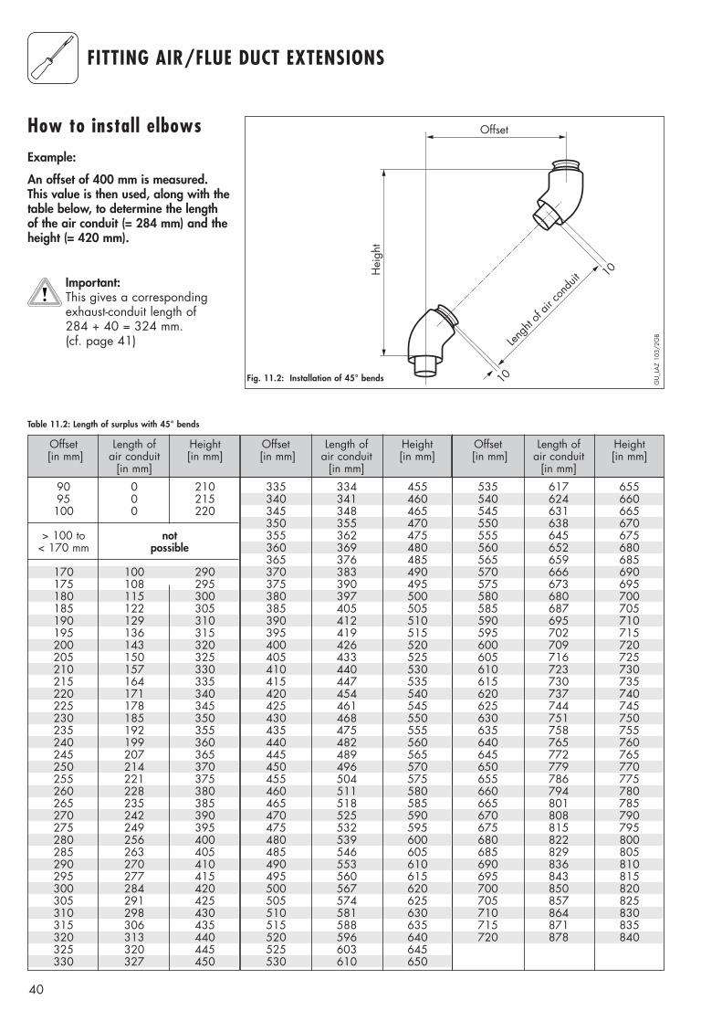
170 100 290175 108 295180 115 300185 122 305190 129 310195 136 315200 143 320205 150 325210 157 330215 164 335220 171 340225 178 345230 185 350235 192 355240 199 360245 207 365250 214 370255 221 375260 228 380265 235 385270 242 390275 249 395280 256 400285 263 405290 270 410295 277 415300 284 420305 291 425310 298 430315 306 435320 313 440325 320 445330 327 450
FITTING AIR/FLUE DUCT EXTENSIONS
Offset Length of Height[in mm] air conduit [in mm]
[in mm]
Offset Length of Height[in mm] air conduit [in mm]
[in mm]
Table 11.2: Length of surplus with 45° bends
Offset Length of Height[in mm] air conduit [in mm]
[in mm]
Hei
ght
Offset
Lengh
t of a
ir con
duit 10
10
How to install elbowsExample:
An offset of 400 mm is measured.This value is then used, along with thetable below, to determine the lengthof the air conduit (= 284 mm) and theheight (= 420 mm).
Important:This gives a correspondingexhaust-conduit length of 284 + 40 = 324 mm. (cf. page 41)
GU
_LA
Z 10
3/2G
B
Fig. 11.2: Installation of 45° bends
335 334 455340 341 460345 348 465350 355 470355 362 475360 369 480365 376 485370 383 490375 390 495380 397 500385 405 505390 412 510395 419 515400 426 520405 433 525410 440 530415 447 535420 454 540425 461 545430 468 550435 475 555440 482 560445 489 565450 496 570455 504 575460 511 580465 518 585470 525 590475 532 595480 539 600485 546 605490 553 610495 560 615500 567 620505 574 625510 581 630515 588 635520 596 640525 603 645530 610 650
535 617 655540 624 660545 631 665550 638 670555 645 675560 652 680565 659 685570 666 690575 673 695580 680 700585 687 705590 695 710595 702 715600 709 720605 716 725610 723 730615 730 735620 737 740625 744 745630 751 750635 758 755640 765 760645 772 765650 779 770655 786 775660 794 780665 801 785670 808 790675 815 795680 822 800685 829 805690 836 810695 843 815700 850 820705 857 825710 864 830715 871 835720 878 840

41

42

43

83
44
49
GB
03
08
/20
02
Mü
Su
bje
ct
to a
lter
atio
n
Head Office Service Solutions 0870 6060 777Vaillant Ltd., Vaillant House Technical Advice 01634 292392Medway City Estate, Trident Close,Rochester, Kent ME2 4EZ