Installation & Operations Manual - P.D. McLaren\users\cindy\documents\word\office\manuals\rdr...
42
c:\users\cindy\documents\word\office\manuals\rdr propane dispenser manual\rdr propane dispenser main document rev-1 oct 9.12.doc Installation & Operations Manual
Transcript of Installation & Operations Manual - P.D. McLaren\users\cindy\documents\word\office\manuals\rdr...
c:\users\cindy\documents\word\office\manuals\rdr propane dispenser manual\rdr propane dispenser main document rev-1 oct 9.12.doc
Installation & Operations Manual
c:\users\cindy\documents\word\office\manuals\rdr propane dispenser manual\rdr propane dispenser main document rev-1 oct 9.12.doc
RDR PROPANE DISPENSER MODELS ET-100 and ET-100D
INDEX PAGE Introduction ................................................................................................................ 1 Electrical/Mechanical
• Data .................................................................................................. 2-3
• Micon 500 ......................................................................................... 4–7
• Terminal Description ......................................................................... 8-9
Installation .................................................................................................................. 10-13
• Base Detail........................................................................................ 14
• Wiring Diagrams ................................................................................ 15-16
• P & ID ............................................................................................... 17-18
• Bill of Material ................................................................................... 19
• Post Installation Check ...................................................................... 20
• Trouble Shooting ............................................................................... 21-25
Appendix .................................................................................................................... 26
• Electrical Components Replacement ................................................. 26
• Pulser Assembly Replacement .......................................................... 27
• Battery Replacement ......................................................................... 30
• Meter Maintenance............................................................................ 31
• Vapor Release and Strainer Maintenance .......................................... 32
• Differential Valve Maintenance .......................................................... 33
• Gear Train Maintenance .................................................................... 34
• Meter Parts Breakdown ..................................................................... 35
• Register Fault Codes ......................................................................... 38
• Service Report .................................................................................. 39
• Warranty ........................................................................................... 40
c:\users\cindy\documents\word\office\manuals\rdr propane dispenser manual\rdr propane dispenser main document rev-1 oct 9.12.doc
Page 1 L.P.G. Dispenser ET-100 and ET-100D
L.P.G. DISPENSER ET-100 and ET-100D INSTALLATION and OPERATION MANUAL
INTRODUCTION General Description The ET Dispenser is designed and manufactured in Canada by P.D. McLaren Limited to provide the Propane Industry with a reliable electronic refueller for dispensing LPG (Liquefied Petroleum Gas). The ET Dispenser, using the Neptune Meter, accurately measures the volume of LPG being dispensed through the use of the Micon 100I computerized electronic register, monitors and compensates the volume according to the temperature of the liquid. The Micon has control of the flow by supplying power to a Motor Control and Solenoid Valve and will stop the flow should an error occur. The volume, price per unit and total sale is then displayed while the Micon updates its internal memory totalizers. The components of the ET Dispenser are contained in a rugged cabinet utilizing an integrated steel frame and stainless steel panels. The computer register displays are visible through impact resistance clear panels. Handle, Detent and Nozzle Holster are made of stainless steel.
c:\users\cindy\documents\word\office\manuals\rdr propane dispenser manual\rdr propane dispenser main document rev-1 oct 9.12.doc
Page 2 L.P.G. Dispenser ET-100 and ET-100D
ELECTRICAL TECHNICAL DATA
Electronic computer type – Micon 500 with ATC Automatic Temperature Compensator. Power Consumption - @ 25 oC 90 – 120 VAC @ .4 amps max. (Operating) - @ -40 oC 90 – 120 VAC @ .8 amps max. Motor Control Output - up to 15 amps @ 120 VAC continuous Solenoid Control Output - up to 1 amp @ 120 VAC continuous Penny Pulser Output ** - solid state switch 5-30 VDC@ 100ma Max. RS < 40 ohms pulser width 7.5m sec. Volume Pulser Output ** - as above except 1 pulser per 1 unit Authorize Input - 90 – 125 VAC @ 80ma max. RIN = 2.7k ohms typical Battery Life In power Fail Mode - 200 hours minimum ** Actual pulse output may lag actual delivery time depending on delivery rate (see pulse width specification). If delivery rate exceeds minimum pulse width specification, pulses will be stored and will eventually be given. Storage rollover will occur at +9999 pulses stored. Function: Operating temperature - -55 oC to +50 oC R.H. 5 to 1005 non condensing Standby temperature (1 day) - -50 oC to +70 oC R.H. 50% maximum Storage temperature (3 days) - -50 oC to +70 oC R.H. 25% maximum Storage temperature indefinite - -40 oC to +50 oC R.H. 50% maximum
c:\users\cindy\documents\word\office\manuals\rdr propane dispenser manual\rdr propane dispenser main document rev-1 oct 9.12.doc
Page 3 L.P.G. Dispenser ET-100 and ET-100D
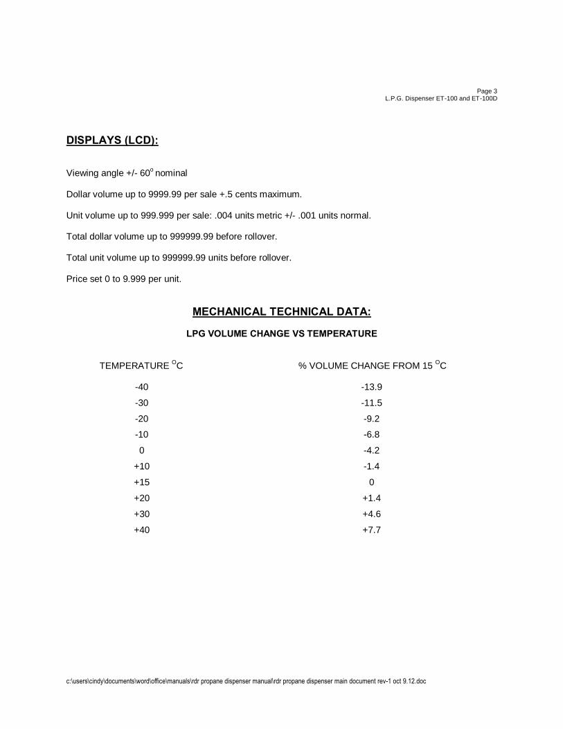
DISPLAYS (LCD): Viewing angle +/- 60o nominal Dollar volume up to 9999.99 per sale +.5 cents maximum. Unit volume up to 999.999 per sale: .004 units metric +/- .001 units normal. Total dollar volume up to 999999.99 before rollover. Total unit volume up to 999999.99 units before rollover. Price set 0 to 9.999 per unit.
MECHANICAL TECHNICAL DATA:
LPG VOLUME CHANGE VS TEMPERATURE TEMPERATURE OC % VOLUME CHANGE FROM 15 OC -40 -13.9
-30 -11.5
-20 -9.2
-10 -6.8
0 -4.2
+10 -1.4
+15 0
+20 +1.4
+30 +4.6
+40 +7.7
c:\users\cindy\documents\word\office\manuals\rdr propane dispenser manual\rdr propane dispenser main document rev-1 oct 9.12.doc
Page 4
L.P.G. Dispenser ET-100 and ET-100D
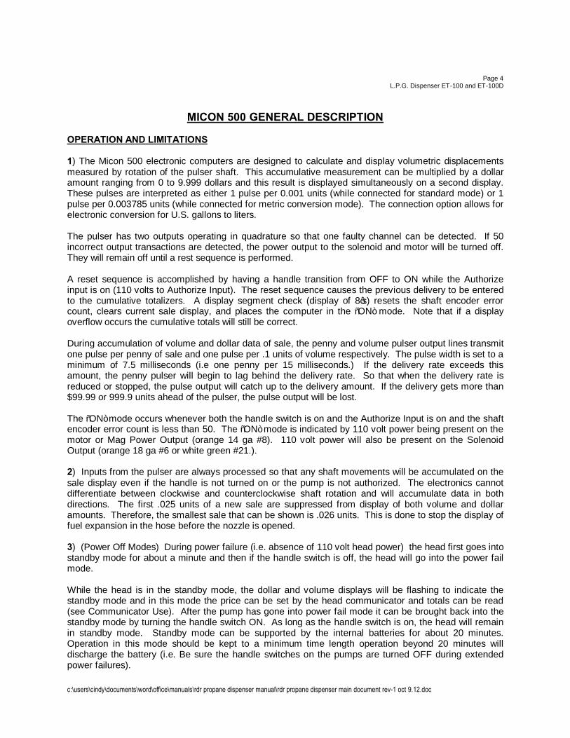
MICON 500 GENERAL DESCRIPTION OPERATION AND LIMITATIONS 1) The Micon 500 electronic computers are designed to calculate and display volumetric displacements measured by rotation of the pulser shaft. This accumulative measurement can be multiplied by a dollar amount ranging from 0 to 9.999 dollars and this result is displayed simultaneously on a second display. These pulses are interpreted as either 1 pulse per 0.001 units (while connected for standard mode) or 1 pulse per 0.003785 units (while connected for metric conversion mode). The connection option allows for electronic conversion for U.S. gallons to liters. The pulser has two outputs operating in quadrature so that one faulty channel can be detected. If 50 incorrect output transactions are detected, the power output to the solenoid and motor will be turned off. They will remain off until a rest sequence is performed. A reset sequence is accomplished by having a handle transition from OFF to ON while the Authorize input is on (110 volts to Authorize Input). The reset sequence causes the previous delivery to be entered to the cumulative totalizers. A display segment check (display of 8’s) resets the shaft encoder error count, clears current sale display, and places the computer in the “ON” mode. Note that if a display overflow occurs the cumulative totals will still be correct. During accumulation of volume and dollar data of sale, the penny and volume pulser output lines transmit one pulse per penny of sale and one pulse per .1 units of volume respectively. The pulse width is set to a minimum of 7.5 milliseconds (i.e one penny per 15 milliseconds.) If the delivery rate exceeds this amount, the penny pulser will begin to lag behind the delivery rate. So that when the delivery rate is reduced or stopped, the pulse output will catch up to the delivery amount. If the delivery gets more than $99.99 or 999.9 units ahead of the pulser, the pulse output will be lost. The “ON” mode occurs whenever both the handle switch is on and the Authorize Input is on and the shaft encoder error count is less than 50. The “ON” mode is indicated by 110 volt power being present on the motor or Mag Power Output (orange 14 ga #8). 110 volt power will also be present on the Solenoid Output (orange 18 ga #6 or white green #21.). 2) Inputs from the pulser are always processed so that any shaft movements will be accumulated on the sale display even if the handle is not turned on or the pump is not authorized. The electronics cannot differentiate between clockwise and counterclockwise shaft rotation and will accumulate data in both directions. The first .025 units of a new sale are suppressed from display of both volume and dollar amounts. Therefore, the smallest sale that can be shown is .026 units. This is done to stop the display of fuel expansion in the hose before the nozzle is opened. 3) (Power Off Modes) During power failure (i.e. absence of 110 volt head power) the head first goes into standby mode for about a minute and then if the handle switch is off, the head will go into the power fail mode. While the head is in the standby mode, the dollar and volume displays will be flashing to indicate the standby mode and in this mode the price can be set by the head communicator and totals can be read (see Communicator Use). After the pump has gone into power fail mode it can be brought back into the standby mode by turning the handle switch ON. As long as the handle switch is on, the head will remain in standby mode. Standby mode can be supported by the internal batteries for about 20 minutes. Operation in this mode should be kept to a minimum time length operation beyond 20 minutes will discharge the battery (i.e. Be sure the handle switches on the pumps are turned OFF during extended power failures).
c:\users\cindy\documents\word\office\manuals\rdr propane dispenser manual\rdr propane dispenser main document rev-1 oct 9.12.doc
Page 5 L.P.G. Dispenser ET-100 and ET-100D
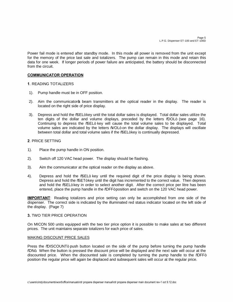
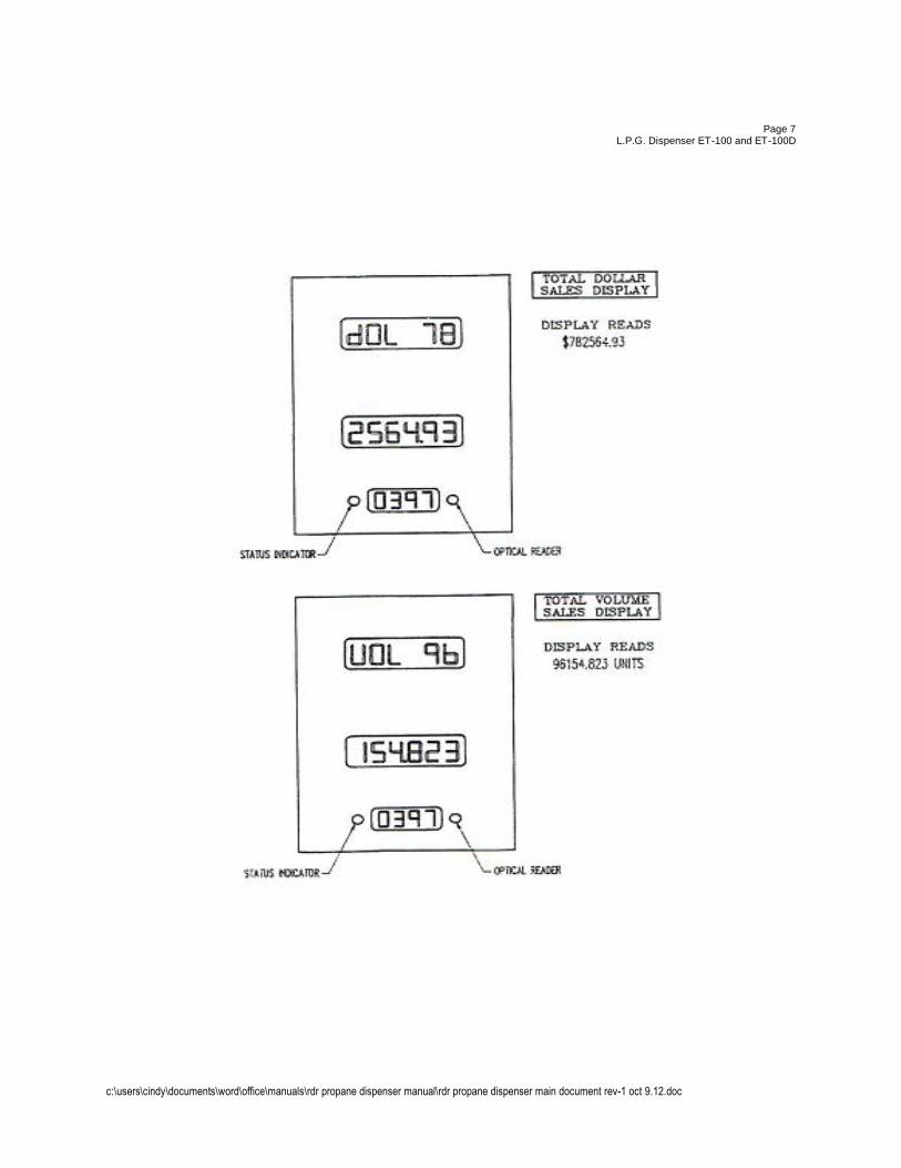
Power fail mode is entered after standby mode. In this mode all power is removed from the unit except for the memory of the price last sale and totalizers. The pump can remain in this mode and retain this data for one week. If longer periods of power failure are anticipated, the battery should be disconnected from the circuit. COMMUNICATOR OPERATION 1. READING TOTALIZERS 1). Pump handle must be in OFF position. 2). Aim the communicator’s beam transmitters at the optical reader in the display. The reader is
located on the right side of price display. 3). Depress and hold the “SEL” key until the total dollar sales is displayed. Total dollar sales utilize the
ten digits of the dollar and volume displays, preceded by the letters “DOL” (see page 16). Continuing to depress the “SEL” key will cause the total volume sales to be displayed. Total volume sales are indicated by the letters “VOL” on the dollar display. The displays will oscillate between total dollar and total volume sales if the “SEL” key is continually depressed.
2. PRICE SETTING 1). Place the pump handle in ON position. 2). Switch off 120 VAC head power. The display should be flashing. 3). Aim the communicator at the optical reader on the display as above. 4). Depress and hold the “SEL” key until the required digit of the price display is being shown.
Depress and hold the “SET” key until the digit has incremented to the correct value. Then depress and hold the “SEL” key in order to select another digit. After the correct price per litre has been entered, place the pump handle in the “OFF” position and switch on the 120 VAC head power.
IMPORTANT: Reading totalizers and price setting can only be accomplished from one side of the dispenser. The correct side is indicated by the illuminated red status indicator located on the left side of the display. (Page 7) 3. TWO TIER PRICE OPERATION On MICON 500 units equipped with the two tier price option it is possible to make sales at two different prices. The unit maintains separate totalizers for each price of sales. MAKING DISCOUNT PRICE SALES Press the “DISCOUNT” push button located on the side of the pump before turning the pump handle “ON”. When the button is pressed the discount price will be displayed and the next sale will occur at the discounted price. When the discounted sale is completed by turning the pump handle to the “OFF” position the regular price will again be displaced and subsequent sales will occur at the regular price.
c:\users\cindy\documents\word\office\manuals\rdr propane dispenser manual\rdr propane dispenser main document rev-1 oct 9.12.doc
Page 6 L.P.G. Dispenser ET-100 and ET-100D
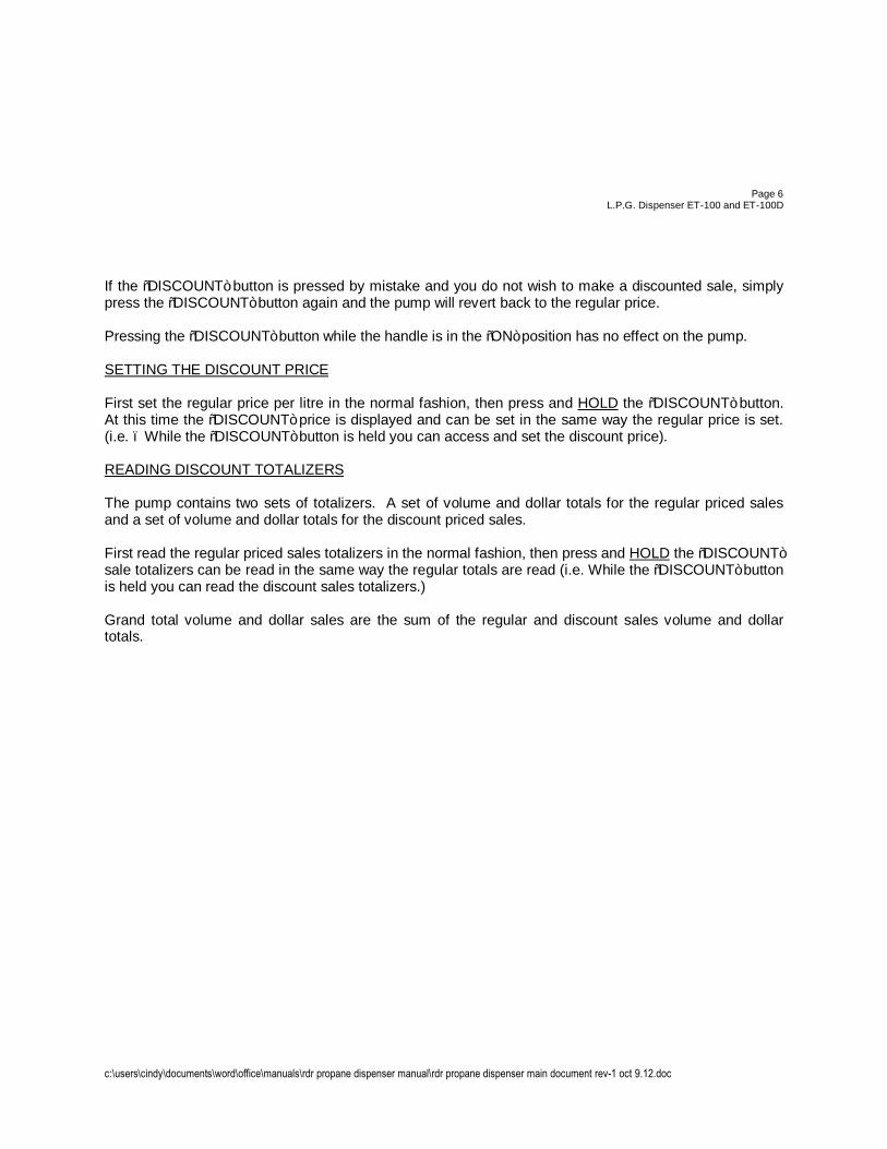
If the “DISCOUNT” button is pressed by mistake and you do not wish to make a discounted sale, simply press the “DISCOUNT” button again and the pump will revert back to the regular price. Pressing the “DISCOUNT” button while the handle is in the “ON” position has no effect on the pump. SETTING THE DISCOUNT PRICE First set the regular price per litre in the normal fashion, then press and HOLD the “DISCOUNT” button. At this time the “DISCOUNT” price is displayed and can be set in the same way the regular price is set. (i.e. – While the “DISCOUNT” button is held you can access and set the discount price). READING DISCOUNT TOTALIZERS The pump contains two sets of totalizers. A set of volume and dollar totals for the regular priced sales and a set of volume and dollar totals for the discount priced sales. First read the regular priced sales totalizers in the normal fashion, then press and HOLD the “DISCOUNT” sale totalizers can be read in the same way the regular totals are read (i.e. While the “DISCOUNT” button is held you can read the discount sales totalizers.) Grand total volume and dollar sales are the sum of the regular and discount sales volume and dollar totals.
c:\users\cindy\documents\word\office\manuals\rdr propane dispenser manual\rdr propane dispenser main document rev-1 oct 9.12.doc
Page 7
L.P.G. Dispenser ET-100 and ET-100D
c:\users\cindy\documents\word\office\manuals\rdr propane dispenser manual\rdr propane dispenser main document rev-1 oct 9.12.doc
Page 8
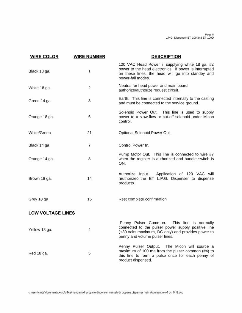
L.P.G. Dispenser ET-100 and ET-100D WIRE COLOR WIRE NUMBER DESCRIPTION
Black 18 ga. 1
120 VAC Head Power – supplying white 18 ga. #2 power to the head electronics. If power is interrupted on these lines, the head will go into standby and power-fail modes.
White 18 ga. 2 Neutral for head power and main board authorize/authorize request circuit.
Green 14 ga. 3 Earth. This line is connected internally to the casting and must be connected to the service ground.
Orange 18 ga. 6 Solenoid Power Out. This line is used to supply power to a slow-flow or cut-off solenoid under Micon control.
White/Green 21 Optional Solenoid Power Out
Black 14 ga 7 Control Power In.
Orange 14 ga. 8 Pump Motor Out. This line is connected to wire #7 when the register is authorized and handle switch is ON.
Brown 18 ga. 14
Authorize Input. Application of 120 VAC will “authorize” the ET L.P.G. Dispenser to dispense products.
Grey 18 ga 15 Rest complete confirmation
LOW VOLTAGE LINES
Yellow 18 ga. 4
Penny Pulser Common. This line is normally connected to the pulser power supply positive line (+30 volts maximum, DC only) and provides power to penny and volume pulser lines.
Red 18 ga. 5
Penny Pulser Output. The Micon will source a maximum of 100 ma from the pulser common (#4) to this line to form a pulse once for each penny of product dispensed.
c:\users\cindy\documents\word\office\manuals\rdr propane dispenser manual\rdr propane dispenser main document rev-1 oct 9.12.doc
Page 9 L.P.G. Dispenser ET-100 and ET-100D
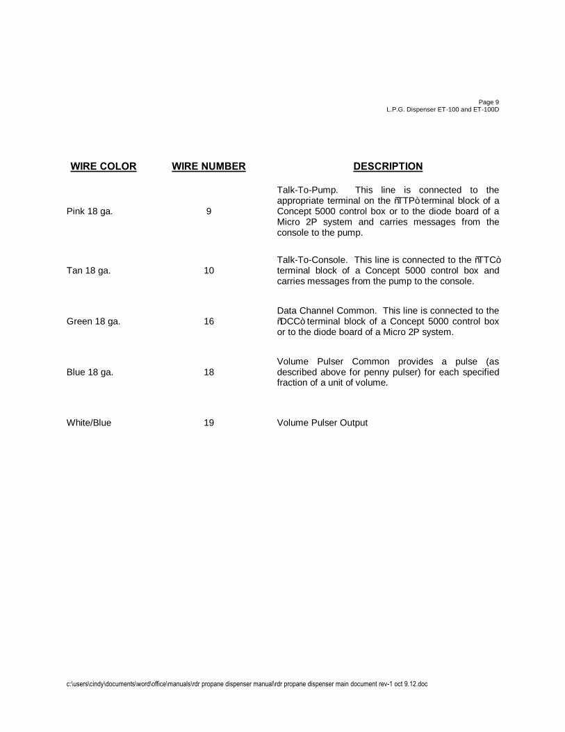
WIRE COLOR WIRE NUMBER DESCRIPTION
Pink 18 ga. 9
Talk-To-Pump. This line is connected to the appropriate terminal on the “TTP” terminal block of a Concept 5000 control box or to the diode board of a Micro 2P system and carries messages from the console to the pump.
Tan 18 ga. 10 Talk-To-Console. This line is connected to the “TTC” terminal block of a Concept 5000 control box and carries messages from the pump to the console.
Green 18 ga. 16 Data Channel Common. This line is connected to the “DCC” terminal block of a Concept 5000 control box or to the diode board of a Micro 2P system.
Blue 18 ga. 18 Volume Pulser Common provides a pulse (as described above for penny pulser) for each specified fraction of a unit of volume.
White/Blue 19 Volume Pulser Output
c:\users\cindy\documents\word\office\manuals\rdr propane dispenser manual\rdr propane dispenser main document rev-1 oct 9.12.doc
Page 10 L.P.G. Dispenser ET-100 and ET-100D
INSTALLATION 1) Installation shall be completed according to CSA standard code B149 1-10. 2) Plan the installation for maximum rate of delivery, sizing the supply tank outlet, piping and valve for
free gravity flow to the pump suction. To accomplish this, locate the pump as close as possible to the supply tank and use short inlet connections with few restrictions. Keep the number of elbows to a minimum and use large radius elbows, wherever possible. To further reduce the likelihood of causing vapor in the pump suction line, install a pump bypass valve in a return line to the supply tank.
3) Locate the dispenser at any convenient place in the pump discharge line. Allow sufficient clearance
for removal of the strainer and vapor release mechanism (6 inches). The clearance for removing the differential valve (front on right-hand assembly) should be 3 ½”. Do not install any bypass around the meter; the valve in such a line might eventually leak, work open, or be left open causing improper measurement.
Under the Weights and Measures Act, “SPECIFICATIONS FOR METERING ASSEMBLIES FOR PROPANE – PROPANE DISPENSER (SVM-3), it reads as follows: INSTALLATION AND USE I1. The supply tank or its piping shall have a 1 ¾” ACME male fitting to allow the propane to be returned to the tank during an inspection. I2. Where the 1 ¾” ACME fitting required by sub-section 6.1 is located more than 30 meters (100 ft.) from the dispenser; means shall be provided by the owner of the dispenser to allow propane to be circulated through the dispenser to provide temperature stabilization of the meter prior to commencing the calibration test. This means may be one of the following but not limited to: A) The installation of a vapor returns line to return liquid propane back to the supply tank. This line must include a 1 ¾” ACME male fitting installed in the dispenser and accessible to the inspector, or B) Adequately sized hose complete with 1 ¾” ACME male fitting to mate with Weights and Measures test equipment. The length of hose provided is to be at least equal to the distance from the 1 ¾” ACME fitting in sub-section 6.1 to the 30 meters (100 ft.) length of hose supplied by Weight and Measures. I3. The combination of static head, inlet piping and pump supplying a dispenser shall provide sufficient pressure so that the dispenser will operate above its minimum rated capacity with minimum cavitation under all normal operating conditions. I4. The vapor return line shall be of sufficient size to vent all vapors in the system under the conditions of use. I5. Under no conditions shall a vapor return line be connected to the tank being filled while making a delivery.
c:\users\cindy\documents\word\office\manuals\rdr propane dispenser manual\rdr propane dispenser main document rev-1 oct 9.12.doc
Page11
L.P.G. Dispenser ET-100 and ET-100D WHEN INSTALLING Secure the connecting piping to prevent strain on the meter casing. Use pipe compound sparingly. VENT LINE The vent line from the dispenser vapor return to the vapor space of the supply tank should be ½” minimum inside diameter tube or pipe. A shut-off valve must be installed in the vapor vent line to permit removal of the strainer for cleaning or when other service is performed on the meter. Make sure you use a union between the valve you provide and the valve in the KRP. THE VAPOUR RELEASE VENT LINE MUST BE RETURNED TO THE SUPPLY TANK AND SHOULD NOT BE MADE A COMMON CONNECTION WITH OTHER VAPOR RETURN LINES OR PUMP BYPASS LINES. When properly installed, this line must permit free flow in either direction. If valve in vent is closed, meter will not function. These instructions must be followed in order to maintain proper function of the differential valves. NOTE: A vapor line should not be used from supply tank being filled. In as much as such connection would cause confusion as to amount delivered as a result of possible vapor in either direction. Connect electrical according to installation instruction on pages 12, 13 and 15.
OPERATION Pressurize the system slowly by allowing vapor flow through the vent line. Then pass sufficient liquid through the system to clear the lines of air and vapor. After starting pump, slowly open outlet valve downstream of the meter. Check the rate of flow after the system is filled; it should not exceed 45 lpm. Adjust the external pump bypass to deliver the maximum practical rate of flow for the least amount of pump pressure. NOTE: The pump relief valve (normally built into the pump assembly) should relieve at a pressure above which the external bypass has been set. Maximum working pressure on the system must not exceed 350 psi. Avoid the use of small diameter hose and excessive pressure to achieve the desired flow rates; these may result in leaking and undue wear on the pump. Although all meters are carefully calibrated and tested after assembly and no changes should be necessary, field calibration is recommended after installation is complete. While the installation is still new, clean the strainer frequently. After the system has been in service only periodic cleaning is necessary.
******READ CAREFULLY****** 1) All wiring must be installed in accordance with national and local electrical codes. 2) WARNING: Substitution of components may impair intrinsic safety.
c:\users\cindy\documents\word\office\manuals\rdr propane dispenser manual\rdr propane dispenser main document rev-1 oct 9.12.doc
Page 12 L.P.G. Dispenser ET-100 and ET-100D
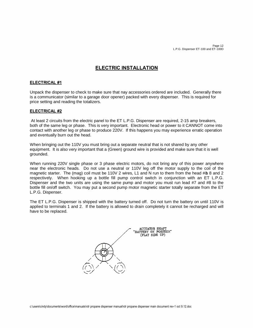
ELECTRIC INSTALLATION ELECTRICAL #1 Unpack the dispenser to check to make sure that nay accessories ordered are included. Generally there is a communicator (similar to a garage door opener) packed with every dispenser. This is required for price setting and reading the totalizers. ELECTRICAL #2 At least 2 circuits from the electric panel to the ET L.P.G. Dispenser are required, 2-15 amp breakers, both of the same leg or phase. This is very important. Electronic head or power to it CANNOT come into contact with another leg or phase to produce 220V. If this happens you may experience erratic operation and eventually burn out the head. When bringing out the 110V you must bring out a separate neutral that is not shared by any other equipment. It is also very important that a (Green) ground wire is provided and make sure that it is well grounded. When running 220V single phase or 3 phase electric motors, do not bring any of this power anywhere near the electronic heads. Do not use a neutral or 110V leg off the motor supply to the coil of the magnetic starter. The (mag) coil must be 110V 2 wires, L1 and N run to them from the head #’s 8 and 2 respectively. When hooking up a bottle fill pump control switch in conjunction with an ET L.P.G. Dispenser and the two units are using the same pump and motor you must run lead #7 and #8 to the bottle fill on/off switch. You may put a second pump motor magnetic starter totally separate from the ET L.P.G. Dispenser. The ET L.P.G. Dispenser is shipped with the battery turned off. Do not turn the battery on until 110V is applied to terminals 1 and 2. If the battery is allowed to drain completely it cannot be recharged and will have to be replaced.
c:\users\cindy\documents\word\office\manuals\rdr propane dispenser manual\rdr propane dispenser main document rev-1 oct 9.12.doc
Page 13 L.P.G. Dispenser ET-100 and ET-100D
After the wiring has been completed you must change the handle shaft actuator as follows: 1) Place the actuator shaft in the OFF position (in the OFF position no continuity will be measured
between wire #14 and #15), with no power on. 2) Remove the cotter pin which secures the coupler assembly to the actuator shaft. 3) Rotate the coupler assembly 90o so that it is resting against the opposite stop pin. ENSURE THAT ACTUATOR SHAFT DOES NOT ROTATE DURING THIS OPERATION. 4) Install the cotter pin and test for continuity between wire #14 and #15. When the actuator shaft is in
the OFF position there should be no continuity between these leads. In the ON position there should be no continuity between these. In the ON position there should be continuity between wire #14 and #15.
Return the actuator shaft to the OFF position.

c:\users\cindy\documents\word\office\manuals\rdr propane dispenser manual\rdr propane dispenser main document rev-1 oct 9.12.doc
Page 14
L.P.G. Dispenser ET-100 and ET-100D
c:\users\cindy\documents\word\office\manuals\rdr propane dispenser manual\rdr propane dispenser main document rev-1 oct 9.12.doc
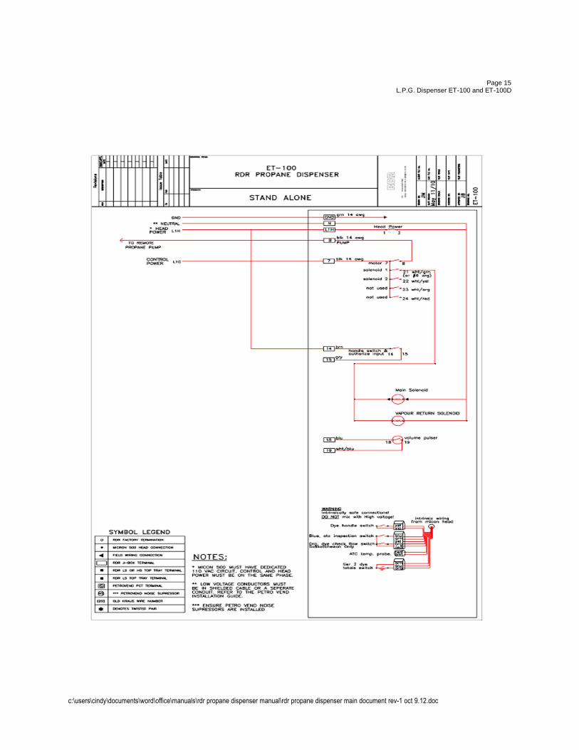
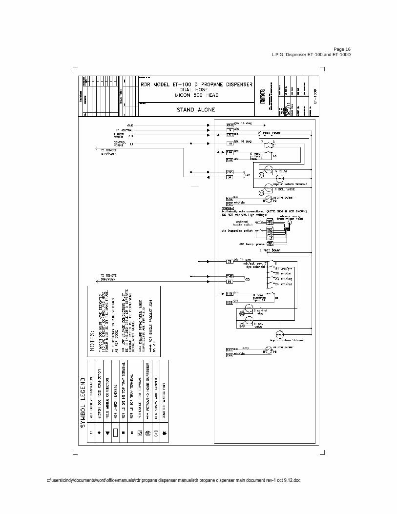
Page 15
L.P.G. Dispenser ET-100 and ET-100D
c:\users\cindy\documents\word\office\manuals\rdr propane dispenser manual\rdr propane dispenser main document rev-1 oct 9.12.doc
Page 16 L.P.G. Dispenser ET-100 and ET-100D
c:\users\cindy\documents\word\office\manuals\rdr propane dispenser manual\rdr propane dispenser main document rev-1 oct 9.12.doc
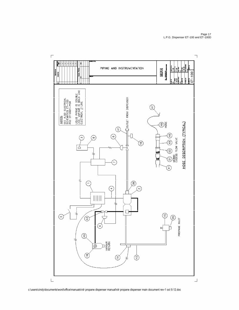
Page 17
L.P.G. Dispenser ET-100 and ET-100D
c:\users\cindy\documents\word\office\manuals\rdr propane dispenser manual\rdr propane dispenser main document rev-1 oct 9.12.doc
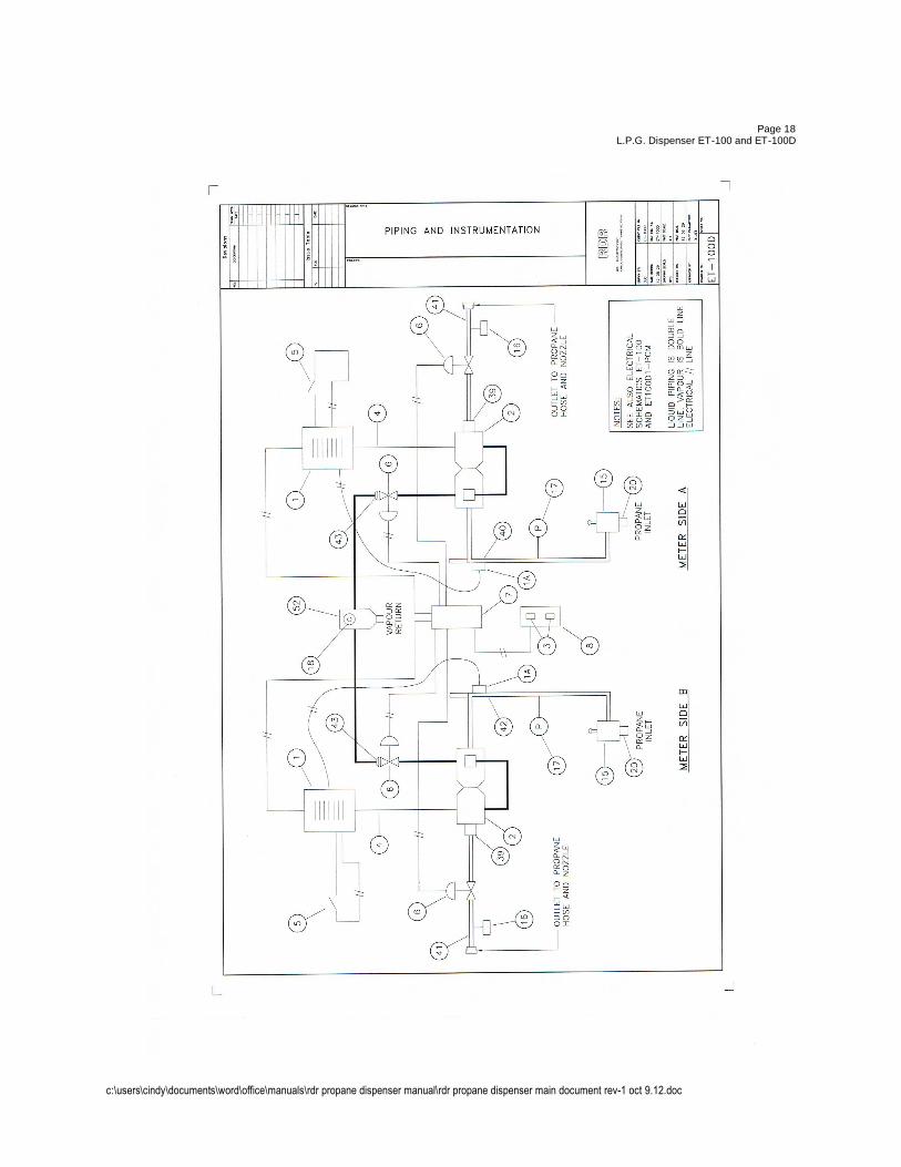
Page 18
L.P.G. Dispenser ET-100 and ET-100D
c:\users\cindy\documents\word\office\manuals\rdr propane dispenser manual\rdr propane dispenser main document rev-1 oct 9.12.doc
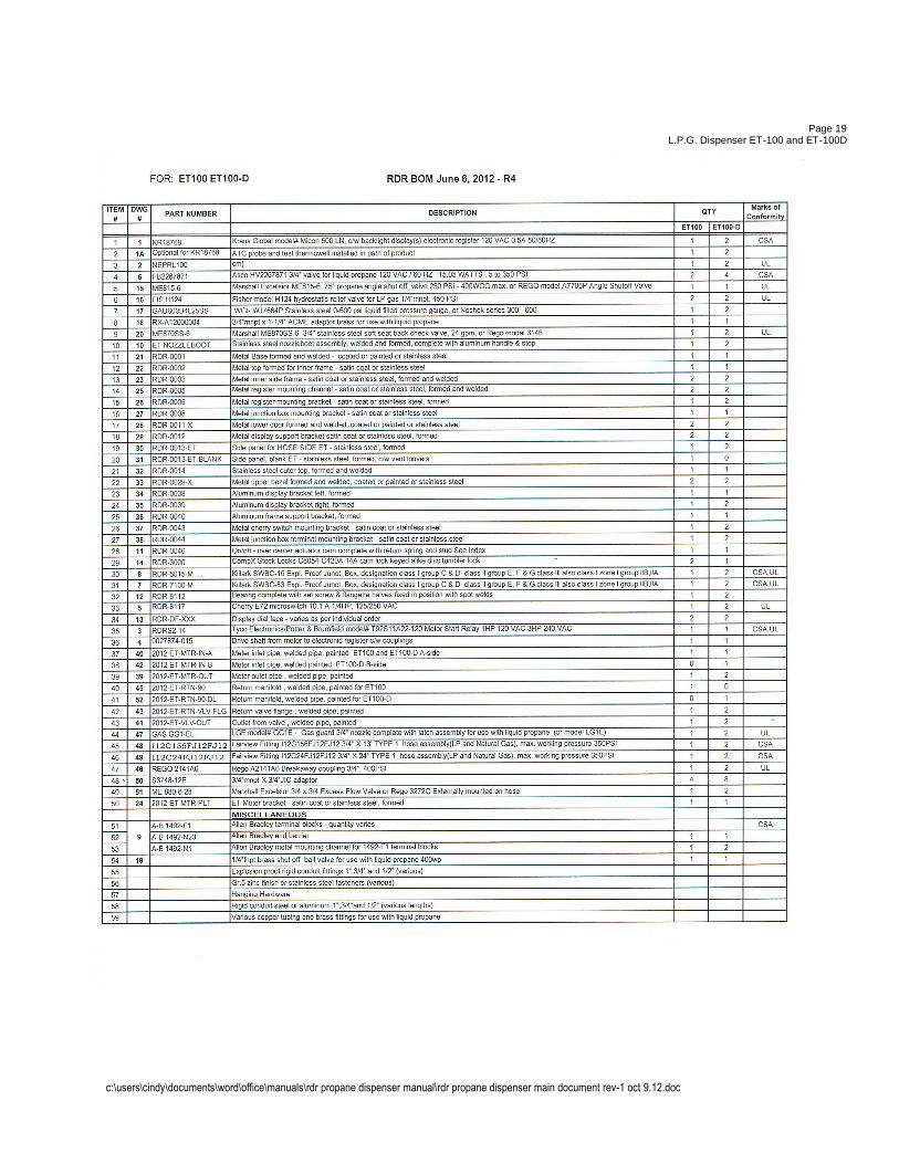
Page 19 L.P.G. Dispenser ET-100 and ET-100D
c:\users\cindy\documents\word\office\manuals\rdr propane dispenser manual\rdr propane dispenser main document rev-1 oct 9.12.doc
Page 20 L.P.G. Dispenser ET-100 and ET-100D
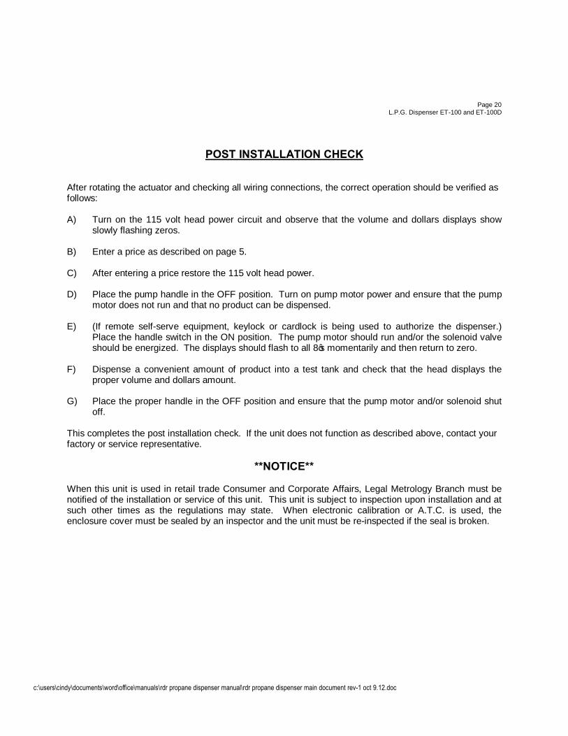
POST INSTALLATION CHECK After rotating the actuator and checking all wiring connections, the correct operation should be verified as follows: A) Turn on the 115 volt head power circuit and observe that the volume and dollars displays show
slowly flashing zeros. B) Enter a price as described on page 5. C) After entering a price restore the 115 volt head power. D) Place the pump handle in the OFF position. Turn on pump motor power and ensure that the pump
motor does not run and that no product can be dispensed. E) (If remote self-serve equipment, keylock or cardlock is being used to authorize the dispenser.)
Place the handle switch in the ON position. The pump motor should run and/or the solenoid valve should be energized. The displays should flash to all 8’s momentarily and then return to zero.
F) Dispense a convenient amount of product into a test tank and check that the head displays the
proper volume and dollars amount. G) Place the proper handle in the OFF position and ensure that the pump motor and/or solenoid shut
off. This completes the post installation check. If the unit does not function as described above, contact your factory or service representative.
**NOTICE** When this unit is used in retail trade Consumer and Corporate Affairs, Legal Metrology Branch must be notified of the installation or service of this unit. This unit is subject to inspection upon installation and at such other times as the regulations may state. When electronic calibration or A.T.C. is used, the enclosure cover must be sealed by an inspector and the unit must be re-inspected if the seal is broken.

c:\users\cindy\documents\word\office\manuals\rdr propane dispenser manual\rdr propane dispenser main document rev-1 oct 9.12.doc
Page 21 L.P.G. Dispenser ET-100 and ET-100D
TROUBLESHOOTING AND REPAIR
PROBLEM POSSIBLE CAUSE
Displays blink slowly on and off with pump handle in the ON position, customer cannot dispense product
• Breaker supplying power to the #1 wire shut-off • No head power. Check 120 VAC supply to leads #1 (hot )
and #2 (neutral) (open connection) • Blown fuse. • Defective KIL 463 control board.
Display blinks slowly on and off with pump handle in the ON position but, customer can dispense product.
• Defective KIL 463 control board.
Micon 500 keeps blowing breaker. • Possible line short on #1 wire (underground) • Varistor (protection for surges on #1 wire) blown.
Displays immediately blank when 120 VAC head power is disconnected.
• Defective battery pack. • Defective KIL 463 control board
Segment (s) on display board staying on all the time or missing entirely. One display or all displays reading 8’s. Other display board reads correctly.
• Defective display board. • Defective display wiring harness (check connections)
Both display boards reading 8’s or erroneous segments being displayed.
• Defective display board. Unplug the display boards one at a time to see if problem clears up.
• Defective display wiring harness. • Defective KIL 463 control board.
Pump motor and/or solenoid valve will not turn on when handle place in the ON position. Reset sequence (previous sale not cleared) when handle turned ON.
• Effective or inoperative linkage to Micon 500 handle shaft (detent).
• No authorize input voltage. Check for 120 VAC on the #14 wire.
• Defective internal microswitch operation (the microswitch which #14 is attached to).
c:\users\cindy\documents\word\office\manuals\rdr propane dispenser manual\rdr propane dispenser main document rev-1 oct 9.12.doc
Page 22 L.P.G. Dispenser ET-100 and ET-100D
TROUBLESHOOTING AND REPAIR
PROBLEM POSSIBLE CAUSE
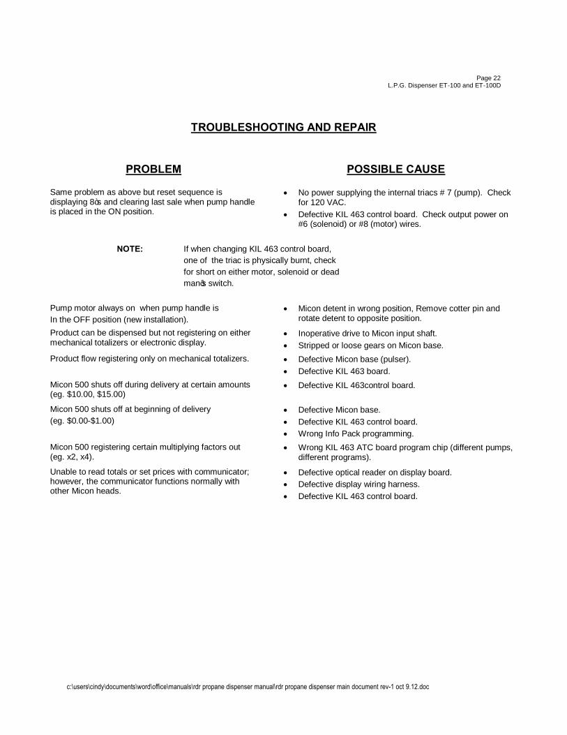
Same problem as above but reset sequence is displaying 8”s and clearing last sale when pump handle is placed in the ON position.
• No power supplying the internal triacs # 7 (pump). Check for 120 VAC.
• Defective KIL 463 control board. Check output power on #6 (solenoid) or #8 (motor) wires.
NOTE: If when changing KIL 463 control board, one of the triac is physically burnt, check for short on either motor, solenoid or dead man’s switch.
Pump motor always on when pump handle is In the OFF position (new installation).
• Micon detent in wrong position, Remove cotter pin and rotate detent to opposite position.
Product can be dispensed but not registering on either mechanical totalizers or electronic display.
• Inoperative drive to Micon input shaft. • Stripped or loose gears on Micon base.
Product flow registering only on mechanical totalizers. • Defective Micon base (pulser). • Defective KIL 463 board.
Micon 500 shuts off during delivery at certain amounts (eg. $10.00, $15.00)
• Defective KIL 463control board.
Micon 500 shuts off at beginning of delivery (eg. $0.00-$1.00)
• Defective Micon base. • Defective KIL 463 control board. • Wrong Info Pack programming.
Micon 500 registering certain multiplying factors out (eg. x2, x4).
• Wrong KIL 463 ATC board program chip (different pumps, different programs).
Unable to read totals or set prices with communicator; however, the communicator functions normally with other Micon heads.
• Defective optical reader on display board. • Defective display wiring harness. • Defective KIL 463 control board.
c:\users\cindy\documents\word\office\manuals\rdr propane dispenser manual\rdr propane dispenser main document rev-1 oct 9.12.doc
Page 23
L.P.G. Dispenser ET-100 and ET-100D
TROUBLESHOOTING AND REPAIR
PROBLEM POSSIBLE CAUSE
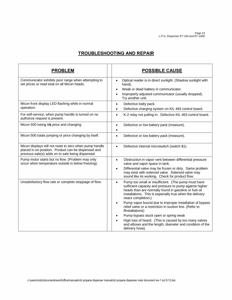
Communicator exhibits poor range when attempting to set prices or read total on all Micon heads.
• Optical reader is in direct sunlight. (Shadow sunlight with hand).
• Weak or dead battery in communicator. • Improperly adjusted communicator (usually dropped).
Try another unit. Micon front display LED flashing while in normal operation.
• Defective batty pack. • Defective charging system on KIL 463 control board.
For self-service, when pump handle is turned on no authorize request is present.
• K-2 relay not pulling in. Defective KIL 463 control board.
Micon 500 losing it’s price and changing • Defective or low battery pack (measure). •
Micon 500 totals jumping or price changing by itself. • Defective or low battery pack (measure).
Micon displays will not reset to zero when pump handle placed in on position. Product can be dispensed and previous sale(s) adds on to sale being dispensed.
• Defective internal microswitch (switch $1).
Pump motor starts but no flow. (Problem may only occur when temperature outside is below freezing).
• Obstruction in vapor vent between differential pressure valve and vapor space in tank.
• Differential valve may be frozen or dirty. Same problem may exist with solenoid valve. Solenoid valve may sound like its working. Check for product flow.
Unsatisfactory flow rate or complete stoppage of flow. • Pump too small or insufficient. (The pump must have sufficient capacity and pressure to pump against higher heads than are normally found in gasoline or fuel oil installations. This is especially true when the delivery nears completion.)
• Pump vapor bound due to improper installation of bypass relief valve or a restriction in suction line. (Refer to “Installation”.)
• Pump bypass stuck open or spring weak • High loss of heard. (This is caused by too many valves
and elbows and the length, diameter and condition of the delivery hose).
c:\users\cindy\documents\word\office\manuals\rdr propane dispenser manual\rdr propane dispenser main document rev-1 oct 9.12.doc
Page 24
L.P.G. Dispenser ET-100 and ET-100D
TROUBLESHOOTING AND REPAIR
PROBLEM POSSIBLE CAUSE
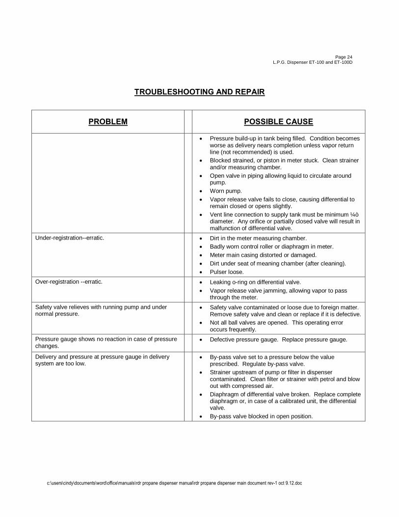
• Pressure build-up in tank being filled. Condition becomes worse as delivery nears completion unless vapor return line (not recommended) is used.
• Blocked strained, or piston in meter stuck. Clean strainer and/or measuring chamber.
• Open valve in piping allowing liquid to circulate around pump.
• Worn pump. • Vapor release valve fails to close, causing differential to
remain closed or opens slightly. • Vent line connection to supply tank must be minimum ¼”
diameter. Any orifice or partially closed valve will result in malfunction of differential valve.
Under-registration--erratic. • Dirt in the meter measuring chamber. • Badly worn control roller or diaphragm in meter. • Meter main casing distorted or damaged. • Dirt under seat of meaning chamber (after cleaning). • Pulser loose.
Over-registration --erratic. • Leaking o-ring on differential valve. • Vapor release valve jamming, allowing vapor to pass
through the meter. Safety valve relieves with running pump and under normal pressure.
• Safety valve contaminated or loose due to foreign matter. Remove safety valve and clean or replace if it is defective.
• Not all ball valves are opened. This operating error occurs frequently.
Pressure gauge shows no reaction in case of pressure changes.
• Defective pressure gauge. Replace pressure gauge.
Delivery and pressure at pressure gauge in delivery system are too low.
• By-pass valve set to a pressure below the value prescribed. Regulate by-pass valve.
• Strainer upstream of pump or filter in dispenser contaminated. Clean filter or strainer with petrol and blow out with compressed air.
• Diaphragm of differential valve broken. Replace complete diaphragm or, in case of a calibrated unit, the differential valve.
• By-pass valve blocked in open position.
c:\users\cindy\documents\word\office\manuals\rdr propane dispenser manual\rdr propane dispenser main document rev-1 oct 9.12.doc
Page 25
L.P.G. Dispenser ET-100 and ET-100D
TROUBLESHOOTING AND REPAIR
PROBLEM POSSIBLE CAUSE
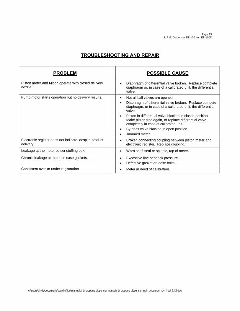
Piston meter and Micon operate with closed delivery nozzle.
• Diaphragm of differential valve broken. Replace complete diaphragm or, in case of a calibrated unit, the differential valve.
Pump motor starts operation but no delivery results. • Not all ball valves are opened. • Diaphragm of differential valve broken. Replace compete
diaphragm, or in case of a calibrated unit, the differential valve.
• Piston in differential valve blocked in closed position. Make piston free again, or replace differential valve completely in case of calibrated unit.
• By-pass valve blocked in open position. • Jammed meter.
Electronic register does not indicate despite product delivery.
• Broken connecting coupling between piston meter and electronic register. Replace coupling.
Leakage at the meter pulser stuffing box. • Worn shaft seal or spindle, top of meter.
Chronic leakage at the main case gaskets. • Excessive line or shock pressure. • Defective gasket or loose bolts.
Consistent over-or under-registration • Meter in need of calibration.
c:\users\cindy\documents\word\office\manuals\rdr propane dispenser manual\rdr propane dispenser main document rev-1 oct 9.12.doc
Page 26
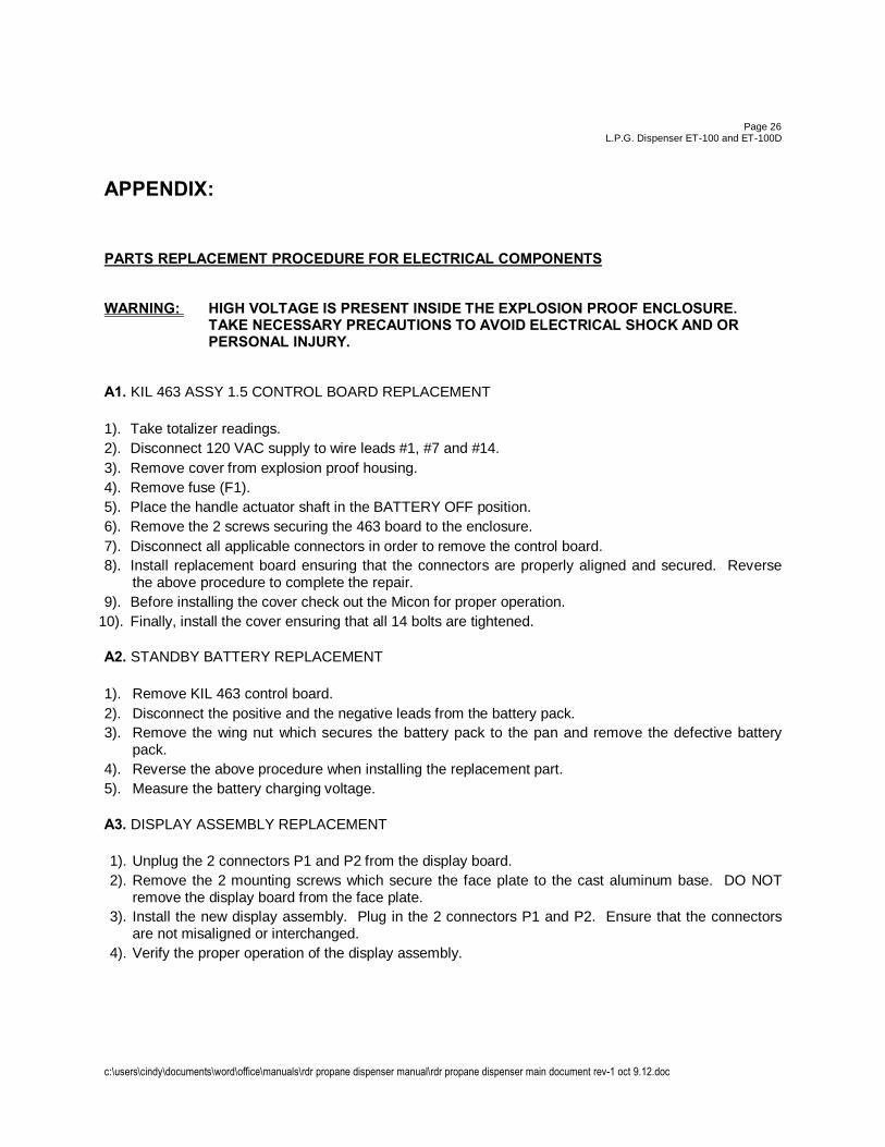
L.P.G. Dispenser ET-100 and ET-100D APPENDIX: PARTS REPLACEMENT PROCEDURE FOR ELECTRICAL COMPONENTS WARNING: HIGH VOLTAGE IS PRESENT INSIDE THE EXPLOSION PROOF ENCLOSURE. TAKE NECESSARY PRECAUTIONS TO AVOID ELECTRICAL SHOCK AND OR PERSONAL INJURY. A1. KIL 463 ASSY 1.5 CONTROL BOARD REPLACEMENT 1). Take totalizer readings. 2). Disconnect 120 VAC supply to wire leads #1, #7 and #14. 3). Remove cover from explosion proof housing. 4). Remove fuse (F1). 5). Place the handle actuator shaft in the BATTERY OFF position. 6). Remove the 2 screws securing the 463 board to the enclosure. 7). Disconnect all applicable connectors in order to remove the control board. 8). Install replacement board ensuring that the connectors are properly aligned and secured. Reverse
the above procedure to complete the repair. 9). Before installing the cover check out the Micon for proper operation.
10). Finally, install the cover ensuring that all 14 bolts are tightened. A2. STANDBY BATTERY REPLACEMENT 1). Remove KIL 463 control board. 2). Disconnect the positive and the negative leads from the battery pack. 3). Remove the wing nut which secures the battery pack to the pan and remove the defective battery
pack. 4). Reverse the above procedure when installing the replacement part. 5). Measure the battery charging voltage. A3. DISPLAY ASSEMBLY REPLACEMENT 1). Unplug the 2 connectors P1 and P2 from the display board. 2). Remove the 2 mounting screws which secure the face plate to the cast aluminum base. DO NOT
remove the display board from the face plate. 3). Install the new display assembly. Plug in the 2 connectors P1 and P2. Ensure that the connectors
are not misaligned or interchanged. 4). Verify the proper operation of the display assembly.
c:\users\cindy\documents\word\office\manuals\rdr propane dispenser manual\rdr propane dispenser main document rev-1 oct 9.12.doc
Page 27
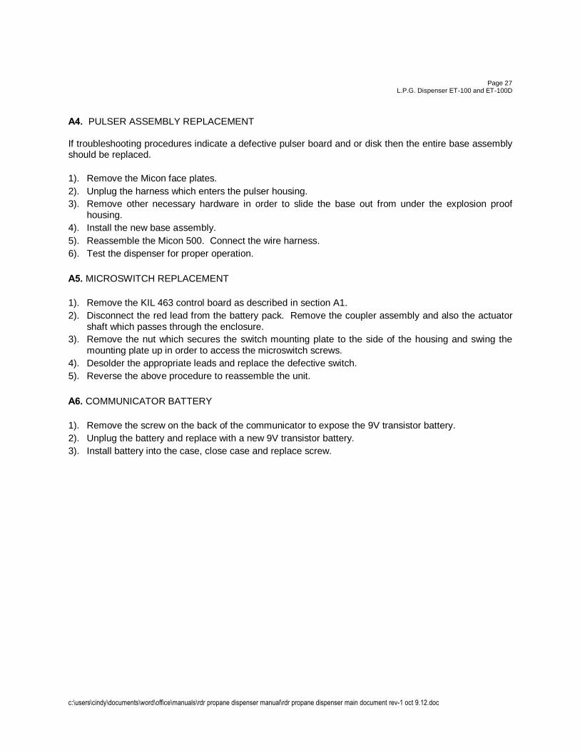
L.P.G. Dispenser ET-100 and ET-100D A4. PULSER ASSEMBLY REPLACEMENT If troubleshooting procedures indicate a defective pulser board and or disk then the entire base assembly should be replaced. 1). Remove the Micon face plates. 2). Unplug the harness which enters the pulser housing. 3). Remove other necessary hardware in order to slide the base out from under the explosion proof
housing. 4). Install the new base assembly. 5). Reassemble the Micon 500. Connect the wire harness. 6). Test the dispenser for proper operation. A5. MICROSWITCH REPLACEMENT 1). Remove the KIL 463 control board as described in section A1. 2). Disconnect the red lead from the battery pack. Remove the coupler assembly and also the actuator
shaft which passes through the enclosure. 3). Remove the nut which secures the switch mounting plate to the side of the housing and swing the
mounting plate up in order to access the microswitch screws. 4). Desolder the appropriate leads and replace the defective switch. 5). Reverse the above procedure to reassemble the unit. A6. COMMUNICATOR BATTERY 1). Remove the screw on the back of the communicator to expose the 9V transistor battery. 2). Unplug the battery and replace with a new 9V transistor battery. 3). Install battery into the case, close case and replace screw.
c:\users\cindy\documents\word\office\manuals\rdr propane dispenser manual\rdr propane dispenser main document rev-1 oct 9.12.doc
Page 28 L.P.G. Dispenser ET-100 and ET-100D
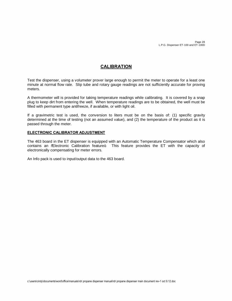
CALIBRATION Test the dispenser, using a volumeter prover large enough to permit the meter to operate for a least one minute at normal flow rate. Slip tube and rotary gauge readings are not sufficiently accurate for proving meters. A thermometer will is provided for taking temperature readings while calibrating. It is covered by a snap plug to keep dirt from entering the well. When temperature readings are to be obtained, the well must be filled with permanent type antifreeze, if available, or with light oil. If a gravimetric test is used, the conversion to liters must be on the basis of: (1) specific gravity determined at the time of testing (not an assumed value), and (2) the temperature of the product as it is passed through the meter. ELECTRONIC CALIBRATOR ADJUSTMENT The 463 board in the ET dispenser is equipped with an Automatic Temperature Compensator which also contains an “Electronic Calibration feature”. This feature provides the ET with the capacity of electronically compensating for meter errors. An Info pack is used to input/output data to the 463 board.
c:\users\cindy\documents\word\office\manuals\rdr propane dispenser manual\rdr propane dispenser main document rev-1 oct 9.12.doc
Page 29 L.P.G. Dispenser ET-100 and ET-100D
AUTOMATIC TEMPERATURE COMPENSATION In addition to electronic calibration, the Automatic Temperature Compensator will compensate the volume of product delivered to the equivalent volume at 15oC. The following procedure could be used to verify the operation of the ATC and a rough check on calibration. 1) Use a tank that has a little propane in it. Weigh the tank with the dispenser hose connected after
you run a small amount of the product. 2) Place the selector switch located on the register support to read gross/net mode. 3) Dispense a convenient volume of product into the tank and record the temperature and weight of
the product in the tank with the hose connected. 4) The volume indicated on the front display is the compensated volume. This volume should agree
directly with the volume weight measured in the test tank. 5) Compare the front and rear displays. There should be a difference in proportion to the difference of
the outside temperature and product temperature and the legal product temperature of 15oC. 6) Return the switch on the rear display to the ON (upwards) position. This completes the testing of the ATC. If you encounter any difficulty please contact your service representative. Do not use this for calibration. ALL CALIBRATION MUST BE DONE COMPLETE WITH WEIGHTS AND MEASURES APPROVED TEST PROCEDURES.
c:\users\cindy\documents\word\office\manuals\rdr propane dispenser manual\rdr propane dispenser main document rev-1 oct 9.12.doc
Page 30 L.P.G. Dispenser ET-100 and ET-100D
STANDBY BATTERY MEASUREMENT Under normal operating conditions the 6 volt standby battery will last at least 5 years. If the life of the standby battery is shortened considerably it could be due to improper charging voltage or prolonged operation on battery power. The KIL 463 control board has a Low Battery detect circuit which causes the red status indicator on the front display to turn on and off approximately once per second. The condition of the standby battery should be verified in the following manner: 1) Place the pump handle in the ON position. 2) Turn off the 120 VAC head power. 3) The red status indicator on the front display should remain ON to indicate the satisfactory condition
of the battery. 4) Turn on the 120 VAC head power.
NOTE: The internal batteries will self-discharge during storage and therefore depending on the degree of discharge during storage and therefore depending on the degree of discharge it may be necessary to allow the battery to charge for up to 8 hours to conduct a valid test. ERRATIC REGISTRATION – REFER TO TROUBLESHOOTING AND REPAIR Erratic registration is usually caused by vaporization of the product, faulty differential valve or vapor release valve (over-registration), or by direct or pipe scale in the measuring chamber (under-registration). Clean the meter, if necessary, as directed in Meter Maintenance. If meter continues to creep when outlet valve is closed, check differential valve seal. CONSISTENT OVER-OR UNDER-REGISTRATION When the meter consistently registers either more or less than is delivered and no other cause in system function can be determined, calibration of the metering system is recommended.
c:\users\cindy\documents\word\office\manuals\rdr propane dispenser manual\rdr propane dispenser main document rev-1 oct 9.12.doc
Page 31
L.P.G. Dispenser ET-100 and ET-100D MICROSWITCH OPERATION CHECK The pump handle which is mechanically coupled to the electronic head actuates 2 internal micro switches. The correct mechanical and electrical operation of this system can be verified in the following manner: 1) The ON/OFF operation of the pump handle should allow the coupler assembly to travel fully
between the stops on the side of the computer. This operation must also rotate the actuator shaft a full 90o.
2) Disconnect 120 VAC supply to the #14 lead. Moving the pump handle from the OFF to the ON
position should cause the displays to flicker briefly. This verifies the proper electrical operation of the microswitch S1.
3) Connect 120 VAC to the #14 lead. Place the pump handle in the OFF position. Measure the
voltage on the #15 lead with respect to neutral. A reading of 0 VAC should be obtained. Place the pump handle in the ON position. A reading of 120 VAC (nominal) should be obtained on the #15 lead. This check verifies the correct operations of microswitch S2. Refer to section A5 if replacement is necessary.
METER MAINTENANCE
For sustained accuracy of the meter, little maintenance is required other than to see that proper conditions of operation are preserved. Once the dispenser has been installed correctly, these conditions consist merely in guarding against foreign matter, such as vapor, sediment or water entering the measuring chamber. However, should any malfunction develop, do not dismantle the meter until the cause of the trouble has first been determined. Refer to Trouble Shooting and Repair. SEDIMENT The liquid passing through the meter measuring chamber must be free of grit and other forms of sediment to prevent unnecessary friction and to eliminate scoring of the piston and chamber walls. Evidence of trouble from the source will be found in under-registration of the meter. Periodic cleaning and inspection of the meter strainer will help to insure against this form of trouble. VAPOR Being an instrument that measures by volume, a meter will record the passage of vapors as well as the liquid being measured. Over-registration will result. Where this condition exists, check for adequacy of the vapor elimination system. WATER Incidental water will cause no damage to the meter. Trouble from this source may be expected when water is allowed to remain in the meter.
c:\users\cindy\documents\word\office\manuals\rdr propane dispenser manual\rdr propane dispenser main document rev-1 oct 9.12.doc
Page 32
L.P.G. Dispenser ET-100 and ET-100D
VAPOR RELEASE AND STRAINER MAINTENANCE SERVICING OF THE VAPOR RELEASE AND STRINER JPORTION OF THE ASSEMBLY CONSISTS ONLY OF OCCASIONAL CLEANING OF THE STRAINER AND WHEN REQUIRED, REPLACEMENT OF A COLLAPSED FLOAT OR SERVICING A STICKING VALVE. TO DISASSEMBLE THE ASSEMBLY:
1) Disconnect the tubing between the differential valve and the vapor release cover .
2) Remove the cap screws on the Vapor release cover and lift and float assembly.
3) Lift out the strainer by four straps.
4) Disassemble the strainer assembly and clean it with compressed air. Inspect for any breaks or other defects and review it if necessary.
5) Reassemble the strainer and install in the housing. The bend upper end of the four straps should be 1/32” to 1/16” above the step in the lower part of the housing. In some cases it may be necessary to rebend the straps to obtain this condition.
6) If float is crushed or damaged, remove cotter pin and replace float. Note: If replacing aluminum float with stainless steel, it will be necessary to change float and valve assembly.
7) Carefully inspect the sleeve valve for any resistance to smooth movement of the sleeve on the stem. Inspect all holes in the sleeve and the stem for foreign material, which could cause sticking of the valve. With the float removed, the sleeve must be moved on the stem by its own weight. If defective, replace sleeve and stem assembly.
8) Inspects the vapor release over o-ring and o-ring groove.
CAUTION
The grooves in which the o-ring gaskets are located must be free of dirt. The flat face against which the o-ring seats must be clean and free of nicks or dents which may allow product to leak past the gasket. Install the float and cover assembly and tighten cover bolts. 9) When interchanging floats or valve assembly, use stainless steel floats only with valve assembly
having a helper spring, to prevent operation of the differential valve.
c:\users\cindy\documents\word\office\manuals\rdr propane dispenser manual\rdr propane dispenser main document rev-1 oct 9.12.doc
Page 33
L.P.G. Dispenser ET-100 and ET-100D
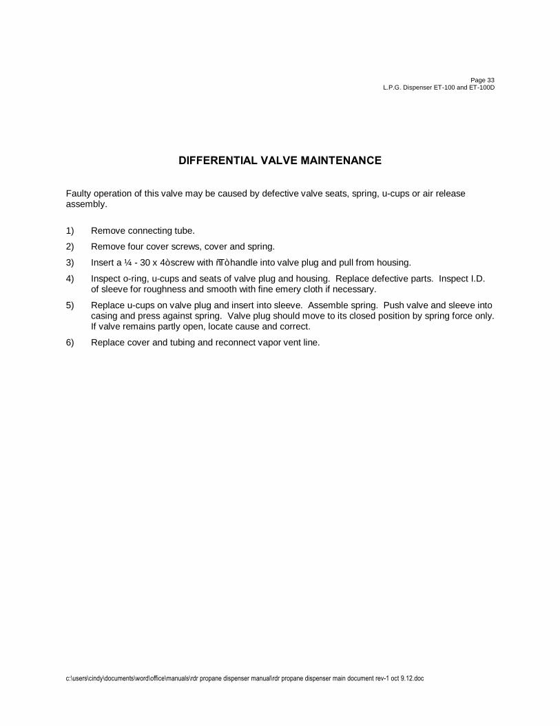
DIFFERENTIAL VALVE MAINTENANCE Faulty operation of this valve may be caused by defective valve seats, spring, u-cups or air release assembly.
1) Remove connecting tube.
2) Remove four cover screws, cover and spring.
3) Insert a ¼ - 30 x 4” screw with “T” handle into valve plug and pull from housing.
4) Inspect o-ring, u-cups and seats of valve plug and housing. Replace defective parts. Inspect I.D. of sleeve for roughness and smooth with fine emery cloth if necessary.
5) Replace u-cups on valve plug and insert into sleeve. Assemble spring. Push valve and sleeve into casing and press against spring. Valve plug should move to its closed position by spring force only. If valve remains partly open, locate cause and correct.
6) Replace cover and tubing and reconnect vapor vent line.
c:\users\cindy\documents\word\office\manuals\rdr propane dispenser manual\rdr propane dispenser main document rev-1 oct 9.12.doc
Page 34 L.P.G. Dispenser ET-100 and ET-100D
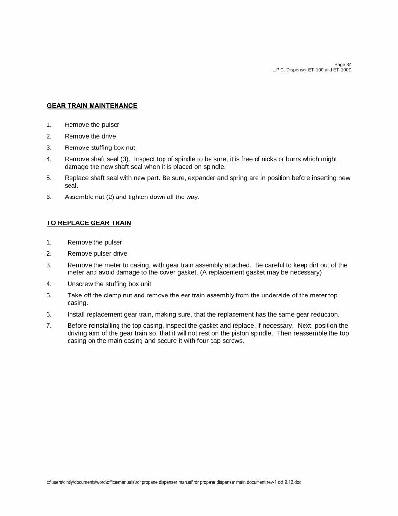
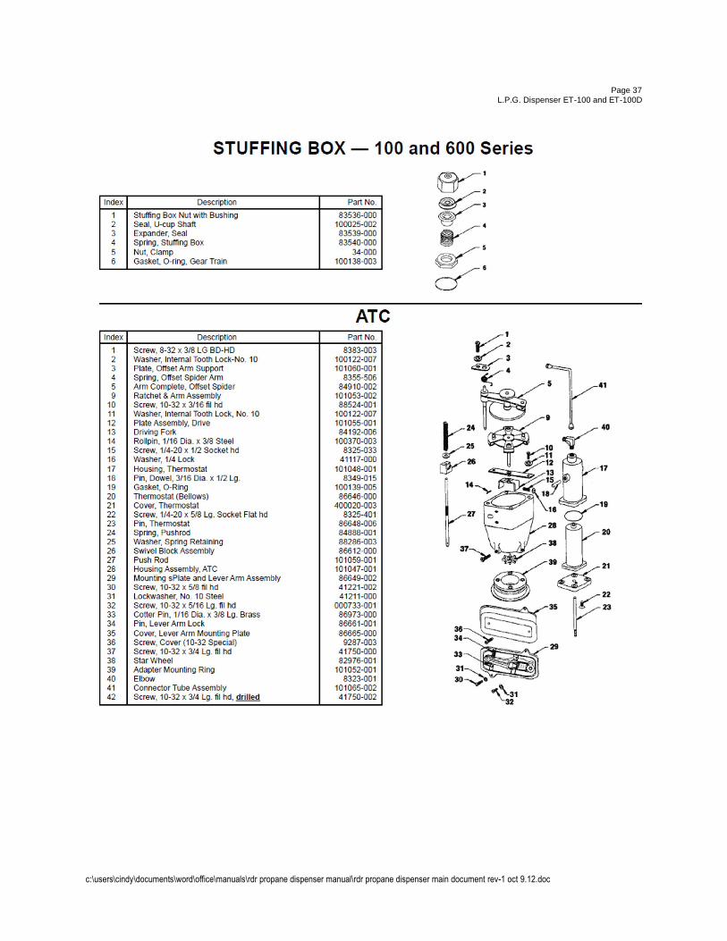
GEAR TRAIN MAINTENANCE
1. Remove the pulser
2. Remove the drive
3. Remove stuffing box nut
4. Remove shaft seal (3). Inspect top of spindle to be sure, it is free of nicks or burrs which might damage the new shaft seal when it is placed on spindle.
5. Replace shaft seal with new part. Be sure, expander and spring are in position before inserting new seal.
6. Assemble nut (2) and tighten down all the way.
TO REPLACE GEAR TRAIN
1. Remove the pulser
2. Remove pulser drive
3. Remove the meter to casing, with gear train assembly attached. Be careful to keep dirt out of the meter and avoid damage to the cover gasket. (A replacement gasket may be necessary)
4. Unscrew the stuffing box unit
5. Take off the clamp nut and remove the ear train assembly from the underside of the meter top casing.
6. Install replacement gear train, making sure, that the replacement has the same gear reduction.
7. Before reinstalling the top casing, inspect the gasket and replace, if necessary. Next, position the driving arm of the gear train so, that it will not rest on the piston spindle. Then reassemble the top casing on the main casing and secure it with four cap screws.
c:\users\cindy\documents\word\office\manuals\rdr propane dispenser manual\rdr propane dispenser main document rev-1 oct 9.12.doc
Page 35 L.P.G. Dispenser ET-100 and ET-100D
c:\users\cindy\documents\word\office\manuals\rdr propane dispenser manual\rdr propane dispenser main document rev-1 oct 9.12.doc
Page 36 L.P.G. Dispenser ET-100 and ET-100D
c:\users\cindy\documents\word\office\manuals\rdr propane dispenser manual\rdr propane dispenser main document rev-1 oct 9.12.doc
Page 37 L.P.G. Dispenser ET-100 and ET-100D
c:\users\cindy\documents\word\office\manuals\rdr propane dispenser manual\rdr propane dispenser main document rev-1 oct 9.12.doc
Page 38
L.P.G. Dispenser ET-100 and ET-100D
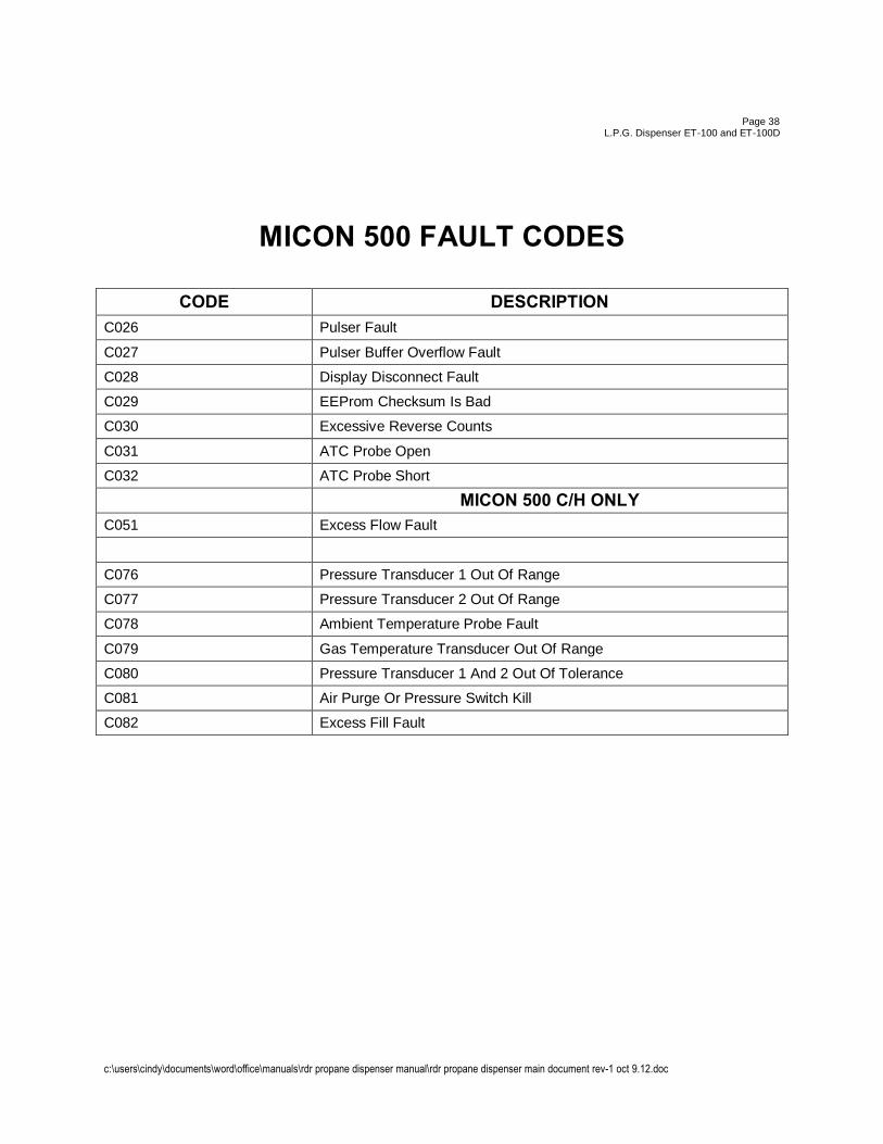
MICON 500 FAULT CODES
CODE DESCRIPTION C026 Pulser Fault
C027 Pulser Buffer Overflow Fault
C028 Display Disconnect Fault
C029 EEProm Checksum Is Bad
C030 Excessive Reverse Counts
C031 ATC Probe Open
C032 ATC Probe Short
MICON 500 C/H ONLY C051 Excess Flow Fault
C076 Pressure Transducer 1 Out Of Range
C077 Pressure Transducer 2 Out Of Range
C078 Ambient Temperature Probe Fault
C079 Gas Temperature Transducer Out Of Range
C080 Pressure Transducer 1 And 2 Out Of Tolerance
C081 Air Purge Or Pressure Switch Kill
C082 Excess Fill Fault
c:\users\cindy\documents\word\office\manuals\rdr propane dispenser manual\rdr propane dispenser main document rev-1 oct 9.12.doc
Page 39 L.P.G. Dispenser ET-100 and ET-100D
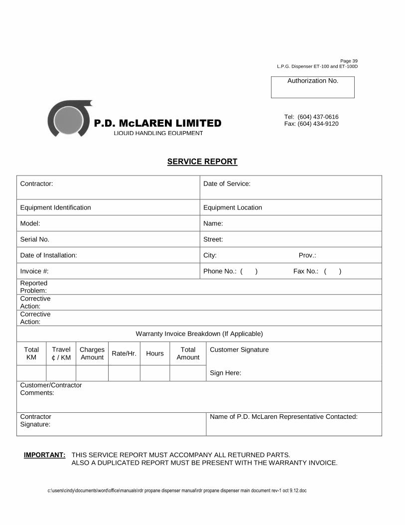
Authorization No.
SERVICE REPORT
Contractor: Date of Service:
Equipment Identification Equipment Location
Model: Name:
Serial No. Street:
Date of Installation: City: Prov.:
Invoice #: Phone No.: ( ) Fax No.: ( )
Reported Problem: Corrective Action: Corrective Action:
Warranty Invoice Breakdown (If Applicable)
Total KM
Travel ¢ / KM
Charges Amount Rate/Hr. Hours Total
Amount Customer Signature
Sign Here:
Customer/Contractor Comments:
Contractor Signature:
Name of P.D. McLaren Representative Contacted:
IMPORTANT: THIS SERVICE REPORT MUST ACCOMPANY ALL RETURNED PARTS. ALSO A DUPLICATED REPORT MUST BE PRESENT WITH THE WARRANTY INVOICE.
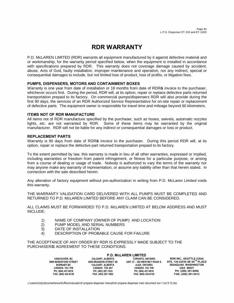
P.D. McLAREN LIMITED LIQUID HANDLING EQUIPMENT
Tel: (604) 437-0616 Fax: (604) 434-9120
c:\users\cindy\documents\word\office\manuals\rdr propane dispenser manual\rdr propane dispenser main document rev-1 oct 9.12.doc
Page 40 L.P.G. Dispenser ET-100 and ET-100D
RDR WARRANTY
P.D. McLAREN LIMITED (RDR) warrants all equipment manufactured by it against defective material and or workmanship, for the warranty period specified below, when the equipment is installed in accordance with specifications prepared by RDR. This warranty does not coverage damage caused by accident, abuse, Acts of God, faulty installation, improper maintenance and operation, nor any indirect, special or consequential damages to include, but not limited loss of product, loss of profits, or litigation fees. PUMPS, DISPENSERS, MOTORS AND CONTAINMENT BOXES Warranty is one year from date of installation or 18 months from date of RDR’s invoice to the purchaser, whichever occurs first. During the period, RDR will, at its option, repair or replace defective parts returned transportation prepaid to its factory. On commercial pumps/dispensers RDR will also provide during the first 90 days, the services of an RDR Authorized Service Representative for on-site repair or replacement of defective parts. The equipment owner is responsible for travel time and mileage beyond 60 kilometers. ITEMS NOT OF RDR MANUFACTURE All items not of RDR manufacture specified by the purchaser, such as hoses, swivels, automatic nozzles lights, etc. are not warranted by RDR. Some of these items may be warranted by the original manufacturer. RDR will not be liable for any indirect or consequential damages or loss or product. REPLACEMENT PARTS Warranty is 90 days from date of RDR’s invoice to the purchaser. During this period RDR will, at its option, repair or replace the defective part returned transportation prepaid to its factory. To the extent permitted by law, this warranty is made in lieu of all other warranties, expressed or implied, including warranties or freedom from patent infringement, or fitness for a particular purpose, or arising from a course of dealing or usage of trade. Nobody is authorized to vary the terms of the warranty nor may anyone make any warranty of representation, or assume any liability other than that herein stated. In connection with the sale described herein. Any alteration of factory equipment without pre-authorization in writing from P.D. McLaren Limited voids this warranty. THE WARRANTY VALIDATION CARD DELIVERED WITH ALL PUMPS MUST BE COMPLETED AND RETURNED TO P.D. McLAREN LIMITED BEFORE ANY CLAIM CAN BE CONSIDERED. ALL CLAIMS MUST BE FORWARDED TO P.D. McLAREN LIMITED AT BELOW ADDRESS AND MUST INCLUDE:
1) NAME OF COMPANY (OWNER OF PUMP) AND LOCATION 2) PUMP MODEL AND SERIAL NUMBERS 3) DATE OF INSTALLATION 4) DESCRIPTION OF PROBABLE CAUSE FOR FAILURE
THE ACCEPTANCE OF ANY ORDER BY RDR IS EXPRESSLY MADE SUBJECT TO THE PURCHASER’S AGREEMENT TO THESE CONDITIONS.
P.D. McLAREN LIMITED VANCOUVER, BC
5069 BERESFORD STREET BURNABY,BC
CANADA V5J 1H8 PH: (604) 437-0616
FAX: (604) 434-9120
CALGARY, ALBERTA 4209 BRANDON STREET SE
CALGARY, ALBERTA CANADA T2G 4A7 PH: (403) 287-1633
FAX: (403) 287-1663
TORONTO, ONTARIO UNIT 27 – 520 WESTNEY ROAD S.
AJAX, ONTARIO CANADA V5J 1H8 PH: (604) 437-0616
FAX: (604) 434-9120
RDR INC., SEATTLE (USA) STE. 130-22530 SE 64TH PLACE
ISSAQUAH, WASHINGTON USA 98027
PH: (206) 391-8060 FAX: (206) 391-5412