Installation, Operation, and Maintenance - Heating and … Clock: On-board real time clock with 7...
82
SAFETY WARNING Only qualified personnel should install and service the equipment. The installation, starting up, and servicing of heating, ventilating, and air-conditioning equipment can be hazardous and requires specific knowledge and training. Improperly installed, adjusted or altered equipment by an unqualified person could result in death or serious injury.When working on the equipment, observe all precautions in the literature and on the tags, stickers, and labels that are attached to the equipment. December 2012 BAS-SVX45D-EN Installation, Operation, and Maintenance Tracer ™ UC600 Programmable Controller Ordering Number: BMUC600AAA0100011
Transcript of Installation, Operation, and Maintenance - Heating and … Clock: On-board real time clock with 7...

SAFETY WARNINGOnly qualified personnel should install and service the equipment.The installation, starting up, andservicing of heating, ventilating, and air-conditioning equipment can be hazardous and requires specificknowledge and training. Improperly installed, adjusted or altered equipment by an unqualified person couldresult in death or serious injury. When working on the equipment, observe all precautions in the literatureand on the tags, stickers, and labels that are attached to the equipment.
December 2012 BAS-SVX45D-EN
Installation, Operation, and
Maintenance
Tracer™ UC600 Programmable ControllerOrdering Number: BMUC600AAA0100011

© 2012Trane All rights reserved BAS-SVX45D-EN
Copyright
© 2012Trane All rights reserved
This document and the information in it are the property ofTrane and may not be usedor reproduced in whole or in part, without the written permission ofTrane.Trane reservesthe right to revise this publication at any time and to make changes to its content withoutobligation to notify any person of such revision or change.
Trademarks
Trane and its logo are trademarks ofTrane in the United States and other countries. Alltrademarks referenced in this document are the trademarks of their respective owners.
Warnings, Cautions, and Notices
Warnings, cautions, and notices are provided in appropriate places throughout thisdocument:
Revision Summary
BAS-SVX45D-EN:
• UL864 certified (smoke control systems)
• Wireless support (WCI)
BAS-SVX45C-EN:
• Creating and viewing Schedules
• Viewing custom graphics
WARNINGIndicates a potentially hazardous situation which, if not avoided, could result indeath or serious injury.
CAUTIONsIndicates a potentially hazardous situation which, if not avoided, could result inminor or moderate injury. It could also be used to alert against unsafe practices.
NOTICE: Indicates a situation that could result in equipment or property-damage onlyaccidents.

Table of Contents
Overview . . . . . . . . . . . . . . . . . . . . . . . . . . . . . . . . . . . . . . . . . . . . . . . . . . . . . . . . . . . . . . 6
Smoke Control Support (UUKL) . . . . . . . . . . . . . . . . . . . . . . . . . . . . . . . . . . . . . . 6
Wireless Comm Interface (WCI) Support . . . . . . . . . . . . . . . . . . . . . . . . . . . . . . 6
Expansion Module Requirements . . . . . . . . . . . . . . . . . . . . . . . . . . . . . . . . . . . . 6
Specifications . . . . . . . . . . . . . . . . . . . . . . . . . . . . . . . . . . . . . . . . . . . . . . . . . . . . . 7
Location of LEDs . . . . . . . . . . . . . . . . . . . . . . . . . . . . . . . . . . . . . . . . . . . . . . . . . . . 7
Hardware Terminations . . . . . . . . . . . . . . . . . . . . . . . . . . . . . . . . . . . . . . . . . . . . . 8
Agency Listings and Compliance . . . . . . . . . . . . . . . . . . . . . . . . . . . . . . . . . . . . . 9
Additional Ordering Options . . . . . . . . . . . . . . . . . . . . . . . . . . . . . . . . . . . . . . . . 9
Required Tools . . . . . . . . . . . . . . . . . . . . . . . . . . . . . . . . . . . . . . . . . . . . . . . . . . . . 9
Dimensions and Clearances . . . . . . . . . . . . . . . . . . . . . . . . . . . . . . . . . . . . . . . . 10
Installation . . . . . . . . . . . . . . . . . . . . . . . . . . . . . . . . . . . . . . . . . . . . . . . . . . . . . . . . . . . . 12
Mounting and Removing the UC600 Controller . . . . . . . . . . . . . . . . . . . . . . . 12
DIN Unit Width . . . . . . . . . . . . . . . . . . . . . . . . . . . . . . . . . . . . . . . . . . . . . . . . . . . 12
Setting Addresses using Rotary Switches . . . . . . . . . . . . . . . . . . . . . . . . . . . . 14Setting the MAC Address . . . . . . . . . . . . . . . . . . . . . . . . . . . . . . . . . . . . . . 14Setting the BACnet Device ID . . . . . . . . . . . . . . . . . . . . . . . . . . . . . . . . . . . 15Rotary Dial Address Settings for Non-Trane Systems . . . . . . . . . . . . . . . 15
UC600 Pre-power Checks . . . . . . . . . . . . . . . . . . . . . . . . . . . . . . . . . . . . . . . . . . . . . . . 17
Resistive Inputs . . . . . . . . . . . . . . . . . . . . . . . . . . . . . . . . . . . . . . . . . . . . . . . . . . . 17
Voltage Inputs . . . . . . . . . . . . . . . . . . . . . . . . . . . . . . . . . . . . . . . . . . . . . . . . . . . . 18
Current Inputs . . . . . . . . . . . . . . . . . . . . . . . . . . . . . . . . . . . . . . . . . . . . . . . . . . . . 18
Binary Inputs . . . . . . . . . . . . . . . . . . . . . . . . . . . . . . . . . . . . . . . . . . . . . . . . . . . . 19
UC600 Power Budget Check in an Un-powered State . . . . . . . . . . . . . . . . . . . . . 20
Calculating AC Power Consumption . . . . . . . . . . . . . . . . . . . . . . . . . . . . . . . . . 20
Calculating DC Power Consumption . . . . . . . . . . . . . . . . . . . . . . . . . . . . . . . . . 21
Wiring and Powering the UC600 . . . . . . . . . . . . . . . . . . . . . . . . . . . . . . . . . . . . . . . . 22
AC Power Warnings and Cautions . . . . . . . . . . . . . . . . . . . . . . . . . . . . . . . . . . . 22
Requirements and Recommendations . . . . . . . . . . . . . . . . . . . . . . . . . . . . . . . 22Wiring and Circuit Requirements . . . . . . . . . . . . . . . . . . . . . . . . . . . . . . . . 22Transformer Requirements . . . . . . . . . . . . . . . . . . . . . . . . . . . . . . . . . . . . 23
Avoid Equipment Damage! . . . . . . . . . . . . . . . . . . . . . . . . . . . . . . . . . . . . . . . . . 23Terminal Connectors and Tug Test . . . . . . . . . . . . . . . . . . . . . . . . . . . . . . 23
Wiring AC Power to the UC600 . . . . . . . . . . . . . . . . . . . . . . . . . . . . . . . . . . . . . 24
Controller Startup and Power Check . . . . . . . . . . . . . . . . . . . . . . . . . . . . . . . . . 25BACnet MS/TP Link Wiring . . . . . . . . . . . . . . . . . . . . . . . . . . . . . . . . . . . . . 26
Wiring Inputs and Outputs . . . . . . . . . . . . . . . . . . . . . . . . . . . . . . . . . . . . . . . . . . . . . 27
BAS-SVX45D-EN 3

Input/Output Requirements . . . . . . . . . . . . . . . . . . . . . . . . . . . . . . . . . . . . . . . . 27
Providing Low-voltage Power for Inputs/Outputs . . . . . . . . . . . . . . . . . . . . . . 28
Input and Output Wiring . . . . . . . . . . . . . . . . . . . . . . . . . . . . . . . . . . . . . . . . . . . 28
Wiring Universal Inputs . . . . . . . . . . . . . . . . . . . . . . . . . . . . . . . . . . . . . . . . . . . . 29Wiring Binary Inputs . . . . . . . . . . . . . . . . . . . . . . . . . . . . . . . . . . . . . . . . . . 29Wiring 0–10 VDC Analog Inputs . . . . . . . . . . . . . . . . . . . . . . . . . . . . . . . . . 30Wiring 0–20 mA Analog Inputs . . . . . . . . . . . . . . . . . . . . . . . . . . . . . . . . . 31Wiring Variable Resistance Analog Inputs . . . . . . . . . . . . . . . . . . . . . . . . 32
Wiring Trane Zone Sensors . . . . . . . . . . . . . . . . . . . . . . . . . . . . . . . . . . . . . . . . 33
Wiring Analog Outputs . . . . . . . . . . . . . . . . . . . . . . . . . . . . . . . . . . . . . . . . . . . . 34
Wiring Binary Outputs . . . . . . . . . . . . . . . . . . . . . . . . . . . . . . . . . . . . . . . . . . . . . 35
Connecting Pressure Transducer Inputs . . . . . . . . . . . . . . . . . . . . . . . . . . . . . . . . . 36
Operation of the UC600 . . . . . . . . . . . . . . . . . . . . . . . . . . . . . . . . . . . . . . . . . . . . . . . . 37
LED Descriptions and Activities . . . . . . . . . . . . . . . . . . . . . . . . . . . . . . . . . . . . . 37
Troubleshooting . . . . . . . . . . . . . . . . . . . . . . . . . . . . . . . . . . . . . . . . . . . . . . . . . . 38Communication Problems . . . . . . . . . . . . . . . . . . . . . . . . . . . . . . . . . . . . . 38Output Points . . . . . . . . . . . . . . . . . . . . . . . . . . . . . . . . . . . . . . . . . . . . . . . . 38Connection Problems . . . . . . . . . . . . . . . . . . . . . . . . . . . . . . . . . . . . . . . . . 39
Configuring the UC600 with the Tracer TU Service Tool . . . . . . . . . . . . . . . . . . . 40
Starting a Session of TU and Connection . . . . . . . . . . . . . . . . . . . . . . . . . . . . 40
Connecting Using Tracer SC . . . . . . . . . . . . . . . . . . . . . . . . . . . . . . . . . . . . . . . . 41Tracer TU Installation and Connection Error Conditions . . . . . . . . . . . . . 43
Upgrading Firmware . . . . . . . . . . . . . . . . . . . . . . . . . . . . . . . . . . . . . . . . . . . . . . 44
Configuring the UC600 and Creating or Editing Points . . . . . . . . . . . . . . . . . 45Configuring the UC600 . . . . . . . . . . . . . . . . . . . . . . . . . . . . . . . . . . . . . . . . 45Using Pre-packaged Solutions (PPS) . . . . . . . . . . . . . . . . . . . . . . . . . . . . . 46Creating or Editing Points for the UC600 . . . . . . . . . . . . . . . . . . . . . . . . . 46Placing Points in Out-of-Service Mode . . . . . . . . . . . . . . . . . . . . . . . . . . . 48Creating Points to Monitor Communication and TGP2 Programs . . . . . 48Creating Points for Timed Override (TOV) and */** Functions . . . . . . . . 49
Monitoring and Viewing the Status of the UC600 . . . . . . . . . . . . . . . . . . . . . . 52
Backup . . . . . . . . . . . . . . . . . . . . . . . . . . . . . . . . . . . . . . . . . . . . . . . . . . . . . . . . . . 53
Restore . . . . . . . . . . . . . . . . . . . . . . . . . . . . . . . . . . . . . . . . . . . . . . . . . . . . . . . . . . 53
Setting Up and Maintaining Schedules . . . . . . . . . . . . . . . . . . . . . . . . . . . . . . 54Creating a Weekly Schedule . . . . . . . . . . . . . . . . . . . . . . . . . . . . . . . . . . . . 54Changing the Schedule Default Value and Adding Events . . . . . . . . . . . 56Adding Exceptions to a Schedule . . . . . . . . . . . . . . . . . . . . . . . . . . . . . . . 58Modifying Exceptions . . . . . . . . . . . . . . . . . . . . . . . . . . . . . . . . . . . . . . . . . 61Deleting Events . . . . . . . . . . . . . . . . . . . . . . . . . . . . . . . . . . . . . . . . . . . . . . 61Deleting Exceptions . . . . . . . . . . . . . . . . . . . . . . . . . . . . . . . . . . . . . . . . . . . 62Deleting a Schedule . . . . . . . . . . . . . . . . . . . . . . . . . . . . . . . . . . . . . . . . . . 62
4 BAS-SVX45D-EN

Custom Graphics . . . . . . . . . . . . . . . . . . . . . . . . . . . . . . . . . . . . . . . . . . . . . . . . . 62Graphics Best Practices . . . . . . . . . . . . . . . . . . . . . . . . . . . . . . . . . . . . . . . . 64
UC600 Commissioning/Troubleshooting in Powered State . . . . . . . . . . . . . . . . 65
Resistive Inputs . . . . . . . . . . . . . . . . . . . . . . . . . . . . . . . . . . . . . . . . . . . . . . . . . . . 66
Voltage Inputs . . . . . . . . . . . . . . . . . . . . . . . . . . . . . . . . . . . . . . . . . . . . . . . . . . . . 67
Current Inputs - Methods 1 or 2 . . . . . . . . . . . . . . . . . . . . . . . . . . . . . . . . . . . . . 68
24 Vac Measurement . . . . . . . . . . . . . . . . . . . . . . . . . . . . . . . . . . . . . . . . . . . . . . 69
Binary Inputs, 24 Vac Detect- Methods 1 or 2 . . . . . . . . . . . . . . . . . . . . . . . . . 70
Binary Inputs- Based on Analog Output Connection . . . . . . . . . . . . . . . . . . . 70
Open-collector Based Binary Sensors . . . . . . . . . . . . . . . . . . . . . . . . . . . . . . . . 71
Voltage Analog Output . . . . . . . . . . . . . . . . . . . . . . . . . . . . . . . . . . . . . . . . . . . . 72
Current Analog Output- Methods 1 or 2 . . . . . . . . . . . . . . . . . . . . . . . . . . . . . . 72
Ground Measurements . . . . . . . . . . . . . . . . . . . . . . . . . . . . . . . . . . . . . . . . . . . . 73
Other Resources . . . . . . . . . . . . . . . . . . . . . . . . . . . . . . . . . . . . . . . . . . . . . . . . . . . . . . . 74
Appendix: Protocol Implementation Conformance Statement (PICS) . . . . . . . 75
Declaration of CE Conformity . . . . . . . . . . . . . . . . . . . . . . . . . . . . . . . . . . . . . . . . . . . 81
BAS-SVX45D-EN 5

Overview
TheTracer UC600 controller, (PN# BMUC600AAA0100011 made in the U.S.A.), is a multi-purpose,programmable, wireless-compatible device. It is designed to control the following types ofequipment:
• Air-handling units (AHUs)
• Rooftop units
• Chillers
• Central heating and cooling plants
• Cooling towers
• Generic input/output (I/O) control
Smoke Control Support (UUKL)
TheTracer UC600 programmable controller is now UL864 certified, making it fully capable ofserving as a component of a UUKL smoke control system along with theTracer SC systemcontroller. For more information, see the “Engineered Smoke Control System Applications Guide”,BAS-APG019-EN.
Wireless Comm Interface (WCI) Support
The wireless comm interface (WCI) is an alternative to BACnet® wired communication links.TheWCI is a wireless communications component (option) added toTracer controllers and iscompatible withTracer UC600.Tracer UC600 firmware must be at Vv4.00.027 or higher forcompatibility with WCI.
Refer to the following documentation for more information:
• Wireless Comm Interface Installation Instructions (X396411710-01)
• Wireless Comm Installation, Operation, and Maintenance (BAS-SVX40-EN)
• Wireless Comm Network Design Best Practices Guide (BAS-SVX55-EN)
Expansion Module Requirements
If additional input or output points are needed, the XM30, XM32, and XM70 expansion modulescan be used.The UC600 controller will support up to 120 combined I/O terminations. See the“Tracer Expansion Module IOM,” (BAS-SVX46-EN), for application and installation information.
6 BAS-SVX45D-EN

Overview
Specifications
The UC600 conforms to the specifications shown inTable 1.
Location of LEDs
Light emitting diodes (LEDs) indicate the operation and communication status of the controller.
To interpret the UC600 LEDs and safely operate the UC600, see “LED Descriptions and Activities,”p. 37.
For detailed information about wiring communication links, refer toTracer SC Unit ControllerWiring Guide (BAS-SVN03) listed in the section, “Other Resources,” p. 74..
Table 1. Specifications
Storage
Temperature: -67°F to 203°F (-55°C to 95°C)
Relative humidity: Between 5% to 95% (non-condensing)
Operating
Temperature: -40°F to 158°F (-40°C to 70°C)
Humidity: Between 5% to 95% (non-condensing)
Power:Input: 20.4–27.6 VAC (24 VAC, ±15% nominal) 50 or 60 Hz, 26 VA(26 VA plus a maximum of 12 VA for each binary output)Output: 24 VDC, ±10%, device max load 600 mA
Time Clock: On-board real time clock with 7 day backup
Mounting weight of controller: Mounting surface must support 1.3 lb. (0.6 kg)
Environmental rating (enclosure): NEMA 1
Installation: UL 840: Category 3
Pollution: UL 840: Degree 2
Figure 1. UC600 LEDs
SERVICE TOOL
SERVICELINK
ACT
IMCMBUSLINK
RX
TX
UC600
ADDRESS0 1
23
456
78
9
x1
0 1
23
456
78
9
x10
0 1
23
456
78
9
x100
BO4BO3BO2BO1 Binary output status LEDs
Power LED
Ethernet LEDs
Communication status (Link, MBUS, IMC)
Service button and LED
BAS-SVX45D-EN 7

Overview
HardwareTerminations
The UC600 supports the following hardware terminations:• Temperature sensors (resistive and thermistor)• Linear inputs 0–20 mA, such as humidity sensors• Linear inputs 0–10 VDC, such as indoor air-quality sensors• Linear outputs 0-20 mA, such as variable frequency drives• Linear outputs 0–10 VDC, such as accuators for dampers and valves• Pulse outputs, such as electric heat or humidifier control• Binary outputs, such as fan start/stop.• One 3-wire pressure transducer input
Table 2. UC600 device connections
Input/Output type Quantity Types Range Notes
Universal input
8
Thermistor10k– Type II, 10k –Type III, 2252– Type II, 20k – Type IV, 100 k
Resistive (Setpoint) 100 – 1M
RTD Balco™ (Ni-Fe), 1k; 375 (Pt), 385 (Pt), 1k
Current 0–20 mA (linear)
Voltage 0–20 VDC (linear)
Binary Dry contact
Pulse Width Accumulator Minimum 20 ms, opened or closed
Universal Input/Analog Output Configure using any combination of analog or binary inputs/analog outputs
6
Thermistor10k– Type II, 10k –Type III, 2252– Type II, 20k – Type IV, 100 k The UC600 provides 600 mA of DC power for 0–
20 mA inputs and/or outputs, and to power expansion modules. See the power budget
table “UC600 Power Budget Check in an Un-powered State,” p. 20.
Inputs
Resistive (setpoint) 100–1M
RTD Balco™ (Ni-Fe), 1k; 375 (Pt), 385 (Pt), 1k
Current –20 mA (linear)
Voltage 0–20 VDC (linear)
Binary Dry contact
Pulse Width Accumulator Minimum 20 ms, opened or closed
Outputs
Current 0–20 mA @16 V
Voltage 0–10 VDC @20 mA
Pulse12.5ms to 1 second (12.5ms resolution), 1 second to 60 seconds (0.5 second resolution)
Binary output 4 Relay (form A) wet 24 VAC, 0.5A maximum Ranges are given per contact.
Pressure input 1 3-wire 0–5 inwc. Pressure input supplied with 5 VDC. Designed for Kavlico™ pressure transducers.
Point total 19
8 BAS-SVX45D-EN

Overview
Agency Listings and Compliance
This section lists compliance with Conformity European (CE) and Underwriters Laboratories (UL)standards for the UC600 controller:
• UL916 PAZX, Open Energy Management Equipment
• UL94-5V, Flammability
• CE Marked
• FCC Part 15, Subpart B, Class B Limit
• UL864 Smoke Control
• BTL Mark—Advanced Application Profile (B-AAC)
Additional Ordering Options
Additional ordering options are available for the UC600:
• TracerTD7 Operator Display (order number: X13651571010)
• TD7 Sealed Ethernet cable (for wet environments) (order number: X19070632020)
• TD7 Display Portable Carry Case (order number: X18210613010)
• TD7 Mounting Bracket (flat surface, fixed position) (order number: X05010511010)
• Tracer XM30 expansion module (order number: X13651537010)
• Tracer XM32 expansion module (order number: X13651563010)
• Tracer XM70 expansion module (order number: X13651568010)
• Tracer BACnetTerm (2 pack) (order number X1365152401)
• Tracer Large enclosure 120 VAC with display capable door (order number: X13651552010)
• Tracer Large enclosure 230 VAC with display capable door (order number: X13651554010)
• Tracer Medium enclosure 120 VAC (order number: X13651559010)
• Tracer Medium enclosure 230 VAC (order number: X13651560010)
• Tracer Small 10" DIN Rail enclosure (order number: X19091354010)
• Power Supply 24VAC to 1.4A 24 VDC for XM modules exceeding UC600 power budget(order number: X1365153801)
• IMC Harness (order number: S3090059462)
RequiredTools
A 1/8 in. (3 mm) flat-bladed screwdriver is required to perform functions such as setting rotaryaddressing switches, tightening or loosening screw terminals, and removing or repositioning thecontroller on DIN rail.
BAS-SVX45D-EN 9

Overview
Dimensions and Clearances
Figure 2. Controller dimensions
AO6UI14
AO5UI13
AO4UI12
AO3UI11
AO2UI10
AO1UI9
BO4BO3BO2BO1
RELAYS 0.5 A MAX
IMC
1
IMC
P1
UI8UI7UI6UI5UI4UI3UI2UI1
IMC
+24VDC
LINKOUT
+24VDC
+24VDC
OUT
24VAC
MBUSOUT
24VAC
XFMR
24VAC
SERVICE TOOL
SERVICELINK
ACT
IMCMBUSLINK
RX
TX
UC600
ADDRESS0 1
23
456
78
9
x1
0 1
23
456
78
9
x10
0 1
23
456
78
9
x100
BO4BO3BO2BO1
8.50 in. (215.9 mm) width (12 DIN units)*
1.73 in (44 mm)
4.00 in. (101.6 mm)
2.17 in. (55 mm)
* DIN Standard 43 880 Built-in Equipment for Electrical Installations, Overall Dimensions and Related Mounting Dimensions. One DIN unit = 18 mm (0.71 in.)
10 BAS-SVX45D-EN

Overview
Figure 3. DIN rail clearances
4.00 in. (101.6 mm)Controller Height
2.0 in. (50.8 mm) Wiring Space Between Controllers (see note)
7.08 in. (180 mm)Centerline to Centerline
Represents Terminal Connector
Note: Allow a minimum of 2.0 in. (50.8 mm)wiring space between controllers,sides of controllers, and bottom ofcabinet.
BAS-SVX45D-EN 11

Installation
This section describes how to install the UC600 onto a DIN rail and set rotary switches.
Mounting and Removing the UC600 Controller
TheTracer UC600 controller should be properly mounted on a DIN rail. Enclosure cabinets thatinclude DIN rails are available fromTrane. See “Additional Ordering Options,” p. 9.
To mount or remove the controller from the DIN rail, follow the illustrated instructions in Figure 4and Figure 5, p. 13. If using a DIN rail from another manufacturer, follow the recommendedinstallation procedures that accompany it.
Important: When mounting the controller in a control cabinet, provide adequate spacingbetween modules to allow for ventilation and heat dissipation.
Notice:
Avoid Equipment Damage
Do not use excessive force to install the controller on the DIN rail. Excessive force could result indamage to the enclosure.
Figure 4. Mounting the UC600
To mount the UC600:
1. Hook device over top of DIN rail.
2. Gently push on lower half of device inthe direction of arrow until the releaseclip clicks into place.
Table 1. DIN unit width measurements
Device Device Width (mm/in) DIN Unit Width (1 unit = 18 mm)
Tracer SC system controller 143.6 mm/5.6 in 8
Tracer UC400 controller 143.6 mm/5.6 in 8
Tracer UC600 controller 215.9 mm/8.5 in 12
Tracer UC800 controller 71.6 mm/2.8 in 4
Tracer XM30 expansion module 53.6 mm/2.1 in 3
Tracer XM32 expansion module 71.6 mm/2.8 in 4
Tracer XM70 expansion module 215.9 mm/8.5 in 12
PM014 power supply module 107.6 mm/4.2 in 6
Tracer BACnet terminator 35.6 mm/1.4 in 2
DIN Unit Width
The following table provides DIN unit width measurements forTrane devices.
12 BAS-SVX45D-EN

Installation
Figure 5. Removing the UC600
To remove or reposition the controller:
1. Disconnect all connectors before removing or repositioning.
2. Insert screwdriver into slotted release clip and gently pry upward with the screwdriver todisengage the clip.
3. While holding tension on the clip, lift device upward to remove or to reposition.
4. If repositioned, push on the device until the release clip clicks back into place to secure thedevice to DIN rail.
BAS-SVX45D-EN 13

Installation
Setting Addresses using Rotary Switches
There are three rotary switches on the front of the UC600 for the purpose of defining a three-digitaddress when the UC600 is installed on a BACnet communications network.The three-digitaddress setting is used as both the BACnet MAC address and the BACnet device ID.
Setting the MAC Address
The MAC address is the rotary dial address. ForTrane systems, this address must be between 1 and127. Although “0,0,0,” is a valid BACnet address,Trane reserves this address for theTracer SCcontroller. For non-Trane systems, see “Rotary Dial Address Settings for Non-Trane Systems,”p. 15. All device addresses on the BACnet MS/TP link must be unique.
• Before powering up the UC600, set the rotary address as shown in Figure 6.
• If the UC600 was previously powered up, do the following if you wish to make changes:
– Make the preferred changes to the rotary address as illustrated in Figure 6.
– Power down the UC600; when re-powered the new MAC address should be active.
Note: Valid MAC addresses used with theTracer UC600 are 001 to 120 for BACnet.
Figure 6. Setting rotary switches
0
5
1
3
6
29
487�
AO6UI14
AO5UI13
AO4UI12
AO3UI11
AO2UI10
AO1UI9
BO4BO3BO2BO1
RELAYS 0.5 A MAX
IMC
1
IMC
P1
UI8UI7UI6UI5UI4UI3UI2UI1
IMC
+24VDC
LINKOUT
+24VDC
+24VDC
OUT
24VAC
MBUSOUT
24VAC
XFMR
24VAC
SERVICE TOOL
SERVICELINK
ACT
IMCMBUSLINK
RX
TX
UC600
ADDRESS0 1
23
456
78
9
x1
0 1
23
456
78
9
x10
0 1
23
456
78
9
x100
BO4BO3BO2BO1
ADDRESS0 1
23
456
78
9
x1
0 1
23
456
78
9
x10
0 1
23
456
78
9
x100
This example illustrates therotary switches after addresseshave been set.
Use a 1/8 in. (3 mm) flatheadscrewdriver to set rotaryswitches. Dial rotates eitherdirection.
Important: Each UC600 device on the BACnet link must have a unique rotary switch setting, otherwise,communication problems will occur.
14 BAS-SVX45D-EN

Installation
Setting the BACnet Device ID
The BACnet device ID uniquely identifies each BACnet device. It can range from 0 to 4194303.Device IDs cannot be shared among devices on the same network. Each UC600 operates as a deviceand requires its own device ID, which defaults to the rotary switch address settings. Refer toFigure 7, p. 16.
There are three ways that the BACnet device ID can be set on the UC600:
• After powering up UC600 for the first time, the UC600 device ID will match the rotary address.
• When installing a UC600 on aTracer SC, the SC will soft set the BACnet device ID based on theSC rotary address, the link number on which it is installed, and the UC600 rotary address. Forexample, theTracer SC will create a BACnet device ID of 101030 under the following conditions:
– The rotary dials on the UC600 are set to 30 (0,3,0), which is also the MAC address.
– TheTracer SC address is “0,1,0”.
– The UC600 is installed on link 1.
• Soft set the BACnet device ID by using theTracerTU service tool.
The BACnet device ID is set to the UC600 MAC address on the rotary switches. If a BACnet deviceID outside of the allowed range is required, you can soft set the device ID by using theTracerTUservice tool.
Important: The UC600 BACnet device ID defaults to the value of the rotary switches if the BACnetdevice ID has not been soft set. If a device ID has been soft set, the rotary switchesare no longer representative of the BACnet device ID.
Note: When integrating the UC600 with third party vendors refer to “Appendix: ProtocolImplementation Conformance Statement (PICS),” p. 69.
Rotary Dial Address Settings for Non-Trane Systems
The Max Master value defines the maximum allowable MAC address (rotary setting) on an MSTPlink.The MAC address is present in each device on the MSTP link. When the last communicatingdevice on the MSTP link polls for the Max Master MAC address with no response, the token rotationwill be restricted on the MSTP link.
For non-Trane systems, the Max Master value must be greater than the unique address settingsfrom the rotary dials. Although 999 is possible from the dials, the maximum allowed number byBACnet is 127.
The Max Master is not adjustable inTrane SC systems. For example, if the MAC address is 101 andthe front-end system has a Max Master value of 100, the device will not be discovered.
Many systems have a minimum BACnet device ID value. Ensure that the device ID is greater thanthis value.
BAS-SVX45D-EN 15

Installation
Figure 7. Rotary switch andTracer SC addressing
ADDRESS0 1
23
456
78
9
x1
0 1
23
456
78
9
x10
0 1
23
456
78
9
x100
ADDRESS0 1
23
456
78
9
x1
0 1
23
456
78
9
x10
0 1
23
456
78
9
x100
ADDRESS0 1
23
456
78
9
x1
0 1
23
456
78
9
x10
0 1
23
456
78
9
x100
ADDRESS0 1
23
456
78
9
x1
0 1
23
456
78
9
x10
0 1
23
456
78
9
x100
MAC: 0Device ID: 001 0 000
Tracer SC = 001
UC600 = 001
UC600 = 002
UC600 = 003
MAC: 1Device ID: 000 0 001
MAC: 3Device ID: 000 0 003
MAC: 2Device ID: 000 0 002
ADDRESS0 1
23
456
78
9
x1
0 1
23
456
78
9
x10
0 1
23
456
78
9
x100
ADDRESS0 1
23
456
78
9
x1
0 1
23
456
78
9
x10
0 1
23
456
78
9
x100
ADDRESS0 1
23
456
78
9
x1
0 1
23
456
78
9
x10
0 1
23
456
78
9
x100
ADDRESS0 1
23
456
78
9
x1
0 1
23
4567
8
9
x10
0 1
23
456
78
9
x100
ADDRESS0 1
23
456
78
9
x1
0 1
23
456
78
9
x10
0 1
23
456
78
9
x100
ADDRESS0 1
23
456
78
9
x1
0 1
23
456
78
9
x10
0 1
23
4567
8
9
x100
SC 001
MS/TP Link 2
Device IDSC Link UC001 1 001
001 1 002
001 1 003
Device IDSC Link UC
001 2 001
001 2 002
001 2 003
MS/TP Link 1
Device ID = 10000
Mac: 1
Mac: 2
Mac: 3
Mac: 1
Mac: 2
Mac: 3
UC600 addressing after installation on Tracer SC
UC600 addressing before installation on Tracer SC
Note: Always start rotary addressing at 1 for each link with no gaps in addresses.
16 BAS-SVX45D-EN

UC600 Pre-power Checks
To avoid equipment damage, a pre-power check for inputs and outputs is recommended beforeapplying power to the UC600.
Before applying power, check for the following:
• All thermistors; check for 10K by using a digital multimeter (DMM).
• Thumbwheels; range between 189 and 890
• Binary outputs; check for any dead shorts.
• Analog outputs; verify that AC voltage is not present and that the load does not have 24 VACor 120 VAC.
This section provides illustrations and methods of how to check the UC600 points beforeconnection has been made and power applied.The step numbers in each illustration correspondto the information in each table. (Refer to Table 2, p. 8 for a list of device connections.)
Note: The illustrations in the section, “UC600 Commissioning/Troubleshooting in Powered State,”p. 65 show the location of the UC600.
Resistive Inputs
Checkout Procedure Measurement Expected Value
Step 1 Measure AC voltage across the resistive termination.VAC 0.0 VAC voltage will affect further measurement.
Step 2 Measure DC voltage across the resistive termination.VDC 0.0 VDC voltage will affect further measurement.
Step 3 Measure the resistance across the resistive termination.Compare the measured resistance with the expected value based on the manufacturer’s specification and current conditions.
BAS-SVX45D-EN 17

UC600 Pre-power Checks
Voltage Inputs
Current Inputs
The sensor sources voltage and is powered.
Checkout Procedure Measurement Expected Value
Step 1 Measure AC voltage across the voltage input.VAC 0.0 VAC voltage will affect further measurement.
Step 2 Measure DC voltage across the voltage termination.Compare the measured voltage with the expected value based on the manufacturer’s specification and current conditions.
The sensor sources 4-20 mA and is powered.
Checkout Procedure Measurement Expected Value
Step 1 Measure AC voltage across the current input.VAC 0.0 VAC voltage will affect further measurement.
Step 2 Measure DC voltage across the current input. VDC 0.0 V. DC voltage will affect further measurement.
Step 3 Measure the DC current across the current input.Compare the measured current with the expected value based on the manufacturer’s specification and current conditions.
18 BAS-SVX45D-EN

UC600 Pre-power Checks
Binary Inputs
Checkout Procedure Measurement Expected Value
Step 1 Measure AC voltage across the resistive termination.VAC 0.0 VAC voltage will affect further measurement.
Step 2 Measure DC voltage across the resistive termination.VDC 0.0 VDC voltage will affect further measurements.
Step 3 Measure the resistance across the resistive termination. contact open = infinity (∞) contact closed = shorted (0 )
BAS-SVX45D-EN 19

UC600 Power Budget Check in an Un-powered State
This section provides information about power budget consumption for the UC600 in anun-powered state.
Calculating AC Power Consumption
The UC600, along with the 24 VAC transformer, can draw up to 26 VA AC power. Observe thefollowing rules when calculating AC power:
• Each UC600 can power a maximum of two additional modules (XM30, XM32, WCI); reserve 8VA for this application.
• Additional expansion modules require an additional power supply module (PM014).
• Each UC600 can power a maximum of 10 points, configured as 4-20 mA in/out (loop-powered).
Each of the components in the following table requires a specific amount of power (VA) from the24 VAC transformer.The following table breaks down the power requirement for each, assumingthat:
• Universal inputs (UI) and universal input/outs (UI/O) draw at most, 20 mA.
• Binary outputs (BO) are not loaded; pilot relays are used.
• Expansion modules will draw full power.
Table 3. UC600 power draw (transformer sizing)
ComponentQuantity and Type of Input/Output
VA Draw Per Input/Output
Maximum Total VA Draw (24 VAC)
UC600 Board
UC600 (alone) 5.5 VA
8 Universal Inputs 0.8 VA 6.4 VA
6 Universal/Analog Outputs 0.8 VA 4.8 VA
4 Binary Outputs 0.3 VA 1.2 VA
1 Pressure Input (Kavlico) 0.1 VA 0.1 VA
Subtotal for UC600 18.0 VA
Tracer TD7 display 21.0 VA
Expansion Modules (Maximum of 2) 8.0 VA
Additional 24 VAC needs, such as actuators and additional VA requirements.
Total for UC600 + expansion modules + end devices 47.0 VA + additional 24 VAC
20 BAS-SVX45D-EN

UC600 Power Budget Check in an Un-powered State
Calculating DC Power Consumption
The UC600 is capable of providing 600 mA of power. Observe the following rules when budgetingfor DC power:
• The UC600 can power a maximum of two small modules (WCIs, expansion modules) and amaximum of 10 points configured as 4-20 mA In/Out (loop powered), simultaneously.
• Include any additional devices where the UC600 is providing 24 VDC that are not part of thecurrent loop.
Use the following table to help determine your DC power supply needs.
Note: If additional 0-20 mA inputs are needed, expansion modules can be powered from a PM014power supply module instead of the UC600. See the “Tracer Expansion Modules IOM,”BAS-SVX46-EN, for more details.
Table 4. DC power budget worksheet
Component No. of terminations mA power draw Total mA
Base electronics 1 x 146 146
Universal inputs/outputs x 20
XM30 expansion module x 115
XM32 expansion module x 100
WCI (can be powered by 24 VAC) x 90
Additional DC powered devices 1 x (varies)
Total DC power draw must be less than 600 mA
BAS-SVX45D-EN 21

Wiring and Powering the UC600
This section describes how to wire and safely power the UC600.
Important: If problems occur after powering refer to the troubleshooting section, “UC600Commissioning/Troubleshooting in Powered State,” p. 65.
Tip: Before powering the UC600, read sections, “UC600 Pre-power Checks,” p. 17 and “UC600Power Budget Check in an Un-powered State,” p. 20.
AC Power Warnings and Cautions
�WARNING
Hazardous Voltage!
Disconnect all electric power, including remote disconnects, before servicing. Follow properlockout and/or tagout procedures to ensure the power cannot be inadvertently energized.Failure to disconnect power before servicing could result in serious injury or death.
� CAUTION
Personal Injury and Equipment Damage!
After installation, verify that the 24 VAC transformer is grounded through the controller. Failureto do so could result in personal injury and/or damage to equipment. Measure the voltagebetween chassis ground and any ground terminal on the controller. Expected result:VAC 4.0 V.Refer to the section, “Wiring AC Power to the UC600,” p. 24.
Notice:
Equipment Damage!
Complete input/output wiring before applying power to the UC600 controller. Failure tocomplete this task may cause damage to the controller or power transformer due to inadvertentconnections to power circuits.The designed units accept only copper conductors. Other typesmay cause equipment damage. Do not share 24VAC between controllers. Sharing 24VAC powermay cause controller damage (refer to the section, “Transformer Requirements,” p. 23).
Requirements and Recommendations
Wiring and Circuit Requirements
All wiring must comply with the National Electrical Code (NEC)™ and local electrical codes.
To ensure proper operation of the UC600, observe the following guidelines:
• The controller should receive AC power from a dedicated power circuit; failure to comply maycause the controller to malfunction.
• A dedicated power circuit disconnect switch must be near the controller, easily accessible bythe operator, and marked as the disconnecting device for the controller.
• Do not run AC power wires in the same wire bundle with input/output wires; failure to complymay cause the controller to malfunction due to electrical noise.
• 18 AWG copper wire is recommended for the circuit between the transformer and thecontroller.
22 BAS-SVX45D-EN

Wiring and Powering the UC600
Transformer Requirements
• AC transformer requirements: UL listed, Class 2 power transformer, 24VAC ±15%, device maxload 26 VA.The transformer must be sized to provide adequate power to the UC600 controller(26 VA) and any external device outputs.
• DC power can be used for 4-20 mA devices and up to two expansion modules (XM30, XM32)and one WCI.
• Include in the total power budget any devices that are powered from the 24 VAC terminal.
• CE-compliant installations:The transformer must be CE marked and SELV compliant per IECstandards.
Avoid Equipment Damage!
Sharing 24 VAC power between controllers could cause equipment damage.
A separate transformer is recommended for each controller.The line input to the transformer mustbe equipped with a circuit breaker sized to manage the maximum transformer line current.
If a single transformer is shared by multiple UC600 controllers:
• The transformer must have sufficient capacity.
• Polarity must be maintained for every UC600 controller powered by the transformer
Important: If polarity is inadvertently reversed between controllers that are powered by thesame transformer, a difference of 24 VAC will occur between the grounds of eachcontroller.The following symptoms could result:
–Partial or full loss of communication on the entire BACnet MS/TP link.
–Improper function of UC600 controller outputs.
–Damage to the transformer or a blown transformer fuse.
Terminal Connectors andTugTest
When wiring to the UC600 using terminal connectors, strip the wires to expose 1/4 in. (7 mm) ofbare wire. Insert each wire into a terminal connector and tighten the terminal screw. A tug test isrecommended after tightening terminal screws to ensure all wires are secure.
Torque Reference: tighten screw terminals to 0.5 to 0.6 N-m(71 to 85 ozf-in or 4.4 to 5.3 lbf-in)
N-m (Newton-meter)
ozf-in (ounce force-inch)
lbf-in (pound force-inch)
BAS-SVX45D-EN 23

Wiring and Powering the UC600
Wiring AC Power to the UC600
1. Connect both secondary wires from the 24 Vac transformer to the XFMR terminals on thedevice.
2. Ensure the device is properly grounded.
Important: This device must be grounded for proper operation!The factory-suppliedground wire must be connected from any chassis ground connection on the deviceto an appropriate earth ground ( ).The chassis ground connection used may be the24 Vac transformer input at the device, or any other chassis ground connection onthe device.
Note: The device is not grounded through the DIN rail connection.
Figure 8. Wiring AC power to the transformer
AO6UI14
AO5UI13
AO4UI12
AO3UI11
AO2UI10
AO1UI9
BO4BO3BO2BO1
RELAYS 0.5 A MAX
IMC
1
IMC
P1
UI8UI7UI6UI5UI4UI3UI2UI1
IMC
+24VDC
LINKOUT
+24VDC
+24VDC
OUT
24VAC
MBUSOUT
24VAC
XFMR
24VAC
SERVICE TOOL
SERVICELINK
ACT
IMCMBUSLINK
RX
TX
UC600
ADDRESS0 1 2
3
456
78
9
x1
0 1 23
456
78
9
x10
0 1 23
456
78
9
x100
BO4BO3BO2BO1
24 VAC transformer
Note: A pigtail connection should be used between the chassis ground on the device and an earth ground, if the device is not grounded through one leg of the transformer wiring.
24 BAS-SVX45D-EN

Wiring and Powering the UC600
Controller Startup and Power Check
1. Verify that the 24 VAC connector and the chassis ground are properly wired.
2. Remove the 24 VAC connector from the UC600.
3. Remove the lockout/tagout from the line voltage power to the electrical cabinet.
4. Using a digital multimeter (DMM), verify that 24 VAC is present at the 24 VAC connector.
If voltage reading is within plus or minus 10%, connect the 24VAC connector to the transformerXMRF input on the UC600.
The following table describes the UC600 service and power LED indicators.
Table 5. LED startup sequence
Power LED Indicates...
Solid Green Normal operation.
Blinking Red Alarm or fault is present.
Solid Red Low voltage or malfunction.
Sequence on Powerup: Illuminates red, then green.
Service LED Indicates...
Solid Green LED has been pressed and remains on until powered down.
Blinking Green Controller not accessing application software.
Not illuminated Normal operation.
Sequence on Power-up: Does not illuminate during power-up.
BAS-SVX45D-EN 25

Wiring and Powering the UC600
BACnet MS/TP Link Wiring
BACnet MS/TP link wiring must be field-supplied and installed in compliance with the NationalElectrical Code and local codes. In addition, the wire must be of the following type:low-capacitance, 18-gauge, stranded, tinned-copper, shielded, twisted-pair.
Important: BACnet links are polarity sensitive; consistent wiring polarity must be maintainedbetween devices.
Note: For more details on this topic, refer to theTracer SC Unit Controller Wiring Guide listedunder “Other Resources,” p. 74.
The illustration below shows an example of BACnet link wiring with a combination of UC600 andUC400 controllers.
Note: A maximum of 20 UC600 controllers are allowed perTracer SC (10 per MSTP link).
Figure 9. BACnet link wiring
LINK IMC
+VDC
P1
SERVICE TOOL
IM
SERVICE TOOL
BI LINK IMC
+VDC
AIAIAI AI AI
P P
TX
RX
LINK IM
SERVI
SERVICE TOOL
IM
+
SERVICESERVICELINK
ACT
IMCMBUSLINK
RX
TX
LINK IMC
P1
IMC
LINK
ACT
IMCMBUSLINK
RX
TX
+VDC
+
Tracer SC UC600 UC600
Zone sensor
BACnet terminator
UC400
BACnet terminator
26 BAS-SVX45D-EN

Wiring Inputs and Outputs
Wiring and configuration for UC600 inputs and outputs is described in this section. Refer to Table 2,p. 8 for a complete list of device connections and descriptions of each type.
Important: If there are problems after powering, refer to the troubleshooting section, “UC600Commissioning/Troubleshooting in Powered State,” p. 65.
Input/Output Requirements
All input/output wiring for the UC600 must meet the following requirements:
• All wiring must be in accordance with the National Electrical Code and local codes.
• Do NOT run input/output wires in the same wire bundle with AC-power wires.
• Use only 18–22 AWG (1.02 mm to 0.65 mm diameter), stranded, tinned-copper, shielded,twisted-pair wire.
• Binary output wiring must not exceed 1,000 ft. (300 m).
• Binary input and 0–20 mA input wiring must not exceed 1,000 ft. (300 m).
• Analog and 24VDC output wiring distances are dependent on the specifications of the receivingunit. Use shielding for analog and 24 VDC outputs.
• Thermistor input and 0–10 VDC input or output wiring must not exceed 300 ft. (100 m).
Avoid Equipment Damage!
Remove power to the UC600 controller before making input or output connections. Failure to doso may cause damage to the controller, power transformer, or input/output devices due toinadvertent connections to power circuits.
Table 6. Maximum wire lengths
Maximum Wire Lengths
Type Inputs Outputs
Binary 1,000 ft (300 m) 1,000 ft (300 m)
0–20 mA 1,000 ft (300 m) 1,000 ft (300 m)
0–10 VDC 300 ft (100 m) 300 ft (100 m)
Thermistor/Resistive 300 ft (100 m) Not Applicable
BAS-SVX45D-EN 27
Wiring Inputs and Outputs
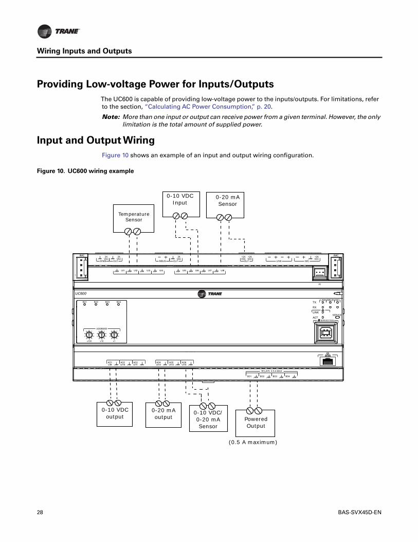
Providing Low-voltage Power for Inputs/Outputs
The UC600 is capable of providing low-voltage power to the inputs/outputs. For limitations, referto the section, “Calculating AC Power Consumption,” p. 20.
Note: More than one input or output can receive power from a given terminal. However, the onlylimitation is the total amount of supplied power.
Input and Output Wiring
Figure 10 shows an example of an input and output wiring configuration.
Figure 10. UC600 wiring example
AO6UI14
AO5UI13
AO4UI12
AO3UI11
AO2UI10
AO1UI9
BO4BO3BO2BO1
RELAYS 0.5 A MAX
IMC
1
IMC
P1
UI8UI7UI6UI5UI4UI3UI2UI1
IMC
+24VDC
LINKOUT
+24VDC
+24VDC
OUT
24VAC
MBUSOUT
24VAC
XFMR
24VAC
SERVICE TOOL
SERVICELINK
ACT
IMCMBUSLINK
RX
TX
UC600
ADDRESS0 1
23
456
78
9
x1
0 1
23
456
78
9
x10
0 1
23
456
78
9
x100
BO4BO3BO2BO1
Temperature Sensor
0-10 VDCInput
0-20 mA Sensor
Powered Output
0-10 VDC/0-20 mA Sensor
0-10 VDCoutput
0-20 mA output
(0.5 A maximum)
28 BAS-SVX45D-EN

Wiring Inputs and Outputs
Wiring Universal Inputs
The UC600 has a total of 14 universal input and output terminals: eight universal inputs locatedon the upper tier and six universal input/output terminals on the bottom tier. Refer to Table 2, p. 8for device connections and ranges.
Wiring Binary Inputs
Binary inputs are two-state inputs, such as fan on/off or alarm resets.
1. Connect the common wire to a common terminal as shown below.
Note: Because the common terminals are in parallel, wiring can be made to any commonterminal.
2. Connect the shield wire to a common terminal at the termination board and tape it back at theinput device.
3. Connect the signal wire to an available input terminal.
4. Use theTracerTU service tool to configure the binary input that references the correspondinghardware termination.
Figure 11. Wiring binary inputs
1
IMC
UI8UI7UI6UI5UI4UI3UI2UI1
UC600
AO6UI14
AO5UI13
AO4UI12
AO3UI11
AO2UI10
AO1UI9
ADDRESS0 1
23
456
78
9
x1
0 1
23
456
78
9
x10
0 1
23
456
78
9
x100
Binary inputs wired to analog outputs/ universal input terminations (bottom tier of the UC600).
Binary Switch
Signal
Common
Tape back shield
Shield
Binary inputs wired to universal input terminations (top tier of the UC600).
Binary Switch
Common
Signal
Tape back shield
BAS-SVX45D-EN 29

Wiring Inputs and Outputs
Wiring 0–10 VDC Analog Inputs
Connect 0–10 VDC analog inputs to sensors such as indoor air quality sensors and pressuresensors.Wiring can be done on the top tier or the bottom tier by using a combination of universaland analog input terminations.
To wire a 0–10 VDC analog input:
1. Connect the shield wire (as common connection) to a common terminal as shown in Figure 12.
2. Connect the signal wire to an available input terminal.
3. Connect the supply wire to a 24 VDC or 24 VAC terminal as required.
4. Use theTracerTU service tool to configure the analog input that references the correspondinghardware termination.
Figure 12. Typical wiring, 0–10 VDC
IMCIMC
AO6UI14
AO5UI13
AO4UI12
AO3UI11
AO2UI10
AO1UI9
BO4BO3BO2BO1
RELAYS 0.5 A MAX
1
P1
UI8UI7UI6UI5UI4UI3UI2UI1
IMC
+24VDC
LINKOUT
+24VDC
+24VDC
OUT
24VAC
MBUSOUT
24VAC
XFMR
24VAC
SERVICE TOOL
SERVICELINK
ACT
IMCMBUSLINK
RX
TX
UC600
ADDRESS0 1
23
456
78
9
x1
0 1
23
456
78
9
x10
0 1
23
456
78
9
x100
BO4BO3BO2BO1
24 VDC
0-10 VDC out
Common
24 VDC
0-10 VDC out
Common
Top tier wiring: Connect to any universal input (UI1 through UI8).
Bottom tier wiring: Connect to any AO/UI input. Connect 24 VDC wire to available 24 VDC on top tier.
30 BAS-SVX45D-EN

Wiring Inputs and Outputs
Wiring 0–20 mA Analog Inputs
Connect any 0–20 mA analog input to sensors such as humidity sensors and pressure sensors.
1. Connect the shield to a common terminal at the terminal board and tape it back at the inputdevice.
Note: Do Not use the shield as the common connection. For 3-wire applications, use a 3-conductor cable with shield and for 2-wire applications, use a 2-conductor cable withseparate shield.
2. Connect the signal wire to an available input terminal.
3. Connect the supply wire to a 24 VDC or 24 VAC terminal as required.
4. Use theTracerTU service tool to configure the analog input that references the correspondinghardware termination.
Figure 13. Typical wiring, 0–20 mA
1
IMC
UI8UI7UI6UI5UI4UI3UI2UI1
OUT
+24VDC
+24VDC
OUT
24VAC
MBUSOUT
24VAC
XFMR
24VAC
OUT
IMC
IMC
+24VDC
LINKOUT
+24VDC
+24VDC
AO6UI14
AO5UI13
AO4UI12
AO3UI11
AO2UI10
AO1UI9
ADDRESS0 1
23
456
78
9
x1
0 1
23
456
78
9
x10
0 1
23
456
78
9
x100
UI8UI7UI6
0-20 mA out
0-20 mA out
Common
24 VDC
24 VDC
Tape shield back
2-wire
3-wire
3-wire
Tape shield back
2-wire
0-20 mA out
24 VDC
Common
24 VDC
0-20 mA out
Top tier wiring: connect to any UI input
Bottom tier wiring: connect to any AO/UI input. Connect 24 VDC wire to available 24 VDC on top tier
BAS-SVX45D-EN 31

Wiring Inputs and Outputs
Wiring Variable Resistance Analog Inputs
Variable resistance analog inputs include 10K thermistors, resistance temperature detectors (RTD,and setpoint thumbwheels on zone sensors.To wire a variable resistance analog input:
1. Connect the shield to a common terminal at the terminal board and tape it back at the inputdevice.
2. Connect the signal wire to an available input terminal.
3. Use theTracerTU service tool to configure the analog input that references the correspondinghardware termination.
Figure 14. Typical wiring, variable resistance
AO6UI14
AO5UI13
AO4UI12
AO3UI11
AO2UI10
AO1UI9
BO4BO3BO2BO1
RELAYS 0.5 A MAX
IMC
1
IMC
P1
UI8UI7UI6UI5UI4UI3UI2UI1
IMC
+24VDC
LINKOUT
+24VDC
+24VDC
OUT
24VAC
MBUSOUT
24VAC
XFMR
24VAC
SERVICE TOOL
SERVICELINK
ACT
IMCMBUSLINK
RX
TX
UC600
ADDRESS0 1
23
456
78
9
x1
0 1
23
456
78
9
x10
0 1
23
456
78
9
x100
BO4BO3BO2BO1
Variable resistance
Temperature Sensor Signal
Signal
Common
Common
Tape back shield
Tape back shieldAO/UI connections located on the bottom tier can also be used. Wire the same way as shown on the top tier.
32 BAS-SVX45D-EN

Wiring Inputs and Outputs
WiringTrane Zone Sensors
The table in Figure 15 shows the terminations on aTrane zone sensor and a typical UC600application.
1. Connect the shield to a common terminal at the terminal board device.
Note: Do Not use the shield as the common connection. For 3-wire applications, use a3-conductor cable with shield and for 2-wire applications, use a 2-conductor cable withseparate shield.
2. Connect the zone sensor wires to any available input (UI, UIO) terminals; refer to table 7 as anexample.
3. Use theTracerTU service tool to configure the analog input that references the correspondinghardware termination.
Figure 15. Typical wiring,Trane zone sensors
AO6UI14
AO5UI13
AO4UI12
AO3UI11
AO2UI10
AO1UI9
BO4BO3BO2BO1
RELAYS 0.5 A MAX
IMC
1
IMC
P1
UI8UI7UI6UI5UI4UI3UI2UI1
IMC
+24VDC
LINKOUT
+24VDC
+24VDC
OUT
24VAC
MBUSOUT
24VAC
XFMR
24VAC
SERVICE TOOL
SERVICELINK
ACT
IMCMBUSLINK
RX
TX
UC600
ADDRESS0 1
23
456
78
9
x1
0 1
23
456
78
9
x10
0 1
23
456
78
9
x100
BO4BO3BO2BO1
4
3
2
1
Table 7. Example zone sensor terminations
Zone Sensor Termination
Zone Sensor Output
UC600 Termination Type Range
1 Zone Temp UI1 Thermistor 10k
2 Ground n/a n/a
3 Zone Temp Setpoint UI2 Resistive 20020k
4 Fan Mode UI3 Resistive 20020k
Note: Example hardware terminations. Any universal input or universal input/analog output may be used for terminating zone temp, zone temp setpoint, or fan mode.Fan mode
Setpoint
Space
BAS-SVX45D-EN 33

Wiring Inputs and Outputs
Wiring Analog Outputs
The UC600 has six analog output terminations.These outputs can be used for 0–10 VDC outputsor 0–20 mA outputs and used to control actuators or secondary controllers.To wire an analogoutput:
1. Connect the shield to a common terminal at the terminal board and tape it back at the inputdevice.
Note: Do Not use the shield as the common connection. For 2-wire applications, use a 2-conductor cable with separate shield.
2. Connect the signal wire to an available output terminal.
3. Connect the supply wire to a 24 VDC or 24 VAC terminal as required.
4. Use theTracerTU service tool to configure the analog output that references the correspondinghardware termination.
Figure 16. Typical wiring, analog outputs
AO6UI14
AO5UI13
AO4UI12
AO3UI11
AO2UI10
AO1UI9
BO4BO3BO2BO1
RELAYS 0.5 A MAX
IMC
1
IMC
P1
UI8UI7UI6UI5UI4UI3UI2UI1
IMC
+24VDC
LINKOUT
+24VDC
+24VDC
OUT
24VAC
MBUSOUT
24VAC
XFMR
24VAC
SERVICE TOOL
SERVICELINK
ACT
IMCMBUSLINK
RX
TX
UC600
ADDRESS0 1
23
456
78
9
x1
0 1
23
456
78
9
x10
0 1
23
456
78
9
x100
BO4BO3BO2BO1
Common
Common
Signal
Signal
24 VDC
Tape back shield
0-20 mA
0-10 volt
34 BAS-SVX45D-EN

Wiring Inputs and Outputs
Wiring Binary Outputs
The UC600 has four binary outputs that are used as powered outputs.
Notice:
Controlling coil-based loads: Inrush current (the initial surge of a current into a load before it attains
normal operating condition) can be three times greater, or more, than the operating current.
Important: Use pilot relays for dry contact outputs for load currents greater than 0.5 amperesand use powered outputs for load currents less than 0.5 amperes.
1. Connect the shield to a common terminal at the terminal board and tape it back at the poweredoutput device.
2. Connect the signal wire to an available output terminal.
3. Use theTracerTU service tool to configure the binary output for binary operation.
Figure 17. Typical wiring, relays (binary outputs)
AO6UI14
AO5UI13
AO4UI12
AO3UI11
AO2UI10
AO1UI9
BO4BO3BO2BO1
RELAYS 0.5 A MAX
IMC
1
IMC
P1
UI8UI7UI6UI5UI4UI3UI2UI1
IMC
+24VDC
LINKOUT
+24VDC
+24VDC
OUT
24VAC
MBUSOUT
24VAC
XFMR
24VAC
SERVICE TOOL
SERVICELINK
ACT
IMCMBUSLINK
RX
TX
UC600
ADDRESS0 1
23
456
78
9
x1
0 1
23
456
78
9
x10
0 1
23
456
78
9
x100
BO4BO3BO2BO1
Pilot relay (24 VAC coil)
Powered output
Tape back shield
Common
Common
Signal
Signal
BAS-SVX45D-EN 35

36 BAS-SVX45D-EN
Connecting PressureTransducer Inputs
The UC600 is equipped with one 3-pin, 5VDC pressure transducer input connection (P1) designedfor Kavlico pressure transducers.Transducers measure duct static pressure in UC600 equipment(VAV AHUs) that is detected from the connected sensor (mounted near the UC600).
Important: To ensure accurate data transmission, use Kavlico pressure transducers. ContactTrane for more details on pressure transducers.
To connect to the pressure transducer input, press the pressure transducer cable onto the pressureinput (P1). Refer to the illustration below.
AO6UI14
AO5UI13
AO4UI12
AO3UI11
AO2UI10
AO1UI9
BO4BO3BO2BO1
RELAYS 0.5 A MAX
IMC
1
IMC
P1
UI8UI7UI6UI5UI4UI3UI2UI1
IMC
+24VDC
LINKOUT
+24VDC
+24VDC
OUT
24VAC
MBUSOUT
24VAC
XFMR
24VAC
SERVICE TOOL
SERVICELINK
ACT
IMCMBUSLINK
RX
TX
UC600
ADDRESS0 1
23
456
78
9
x1
0 1
23
456
78
9
x10
0 1
23
456
78
9
x100
BO4BO3BO2BO1
Pressure Input P1

Operation of the UC600
LED Descriptions and Activities
The following table provides a description of LED activity, indicators, and troubleshooting tips.Refer to Figure 1, p. 7, for locations of the LEDs.
Note: Points that are in an alarm state when the notification type is configured as “alarm” willcause the power LED to flash red. If the notification type of a point is configured as “event,”the power LED will not flash when the point is in an alarm state. Modbus is not supportedat this time.
Table 8. LED identification and interpretation
LED type LED activity Indicates... Troubleshooting/Notes
Power
Solid green Normal operationSequence on powerup: Illuminates red, then flashes green, then solid green. Solid red Low voltage or malfunction
Blinking red Alarm or fault is present (*see note)
Communication (Link, MBUS, IMC)
TX (transmit) blinks green Normal operation; blinks at a fixed rate when transferring data to other devices on the link
TX LED: Regardless of connectivity, the TX will blink as it searches for devices to communicate with.
RX (receive) blinks yellow Normal operation; blinks at a fixed rate when receiving data from other devices on the link
RX on solid (yellow) Reverse polarity is present
LED not illuminated The controller is not detecting communication
• Cycle the power to reestablish communication.
• Verfiy that the controller is capable of communicating with other devices on the link.
• Check polarity and baud rate.
Service Solid green
LED has been pressed and remains on until powered down (does not affect normal operation)
LED not illuminated Normal operation
Binary outputs (BO1 through BO4
Solid yellow Relay coil energized
LED not illuminated Relay coil de-energized or No command
Ethernet LINK on solid (green) Valid Ethernet connection
ACT flickers (yellow) Data transmission and reception
BAS-SVX45D-EN 37

Operation of the UC600
Troubleshooting
The section provides troubleshooting solutions for problems that sometimes occur with theUC600.
Communication Problems
Problem:The UC600 is not communicating withTracer SC, but can communicate withTracerTUusing a direct USB connection.
Possible cause:The “Soft Set Device ID” check box was unchecked after the UC600 was installedonto theTracer SC.
Possible solution: Reinstall the UC600 device onto theTracer SC.
1. Verify that the UC600 device ID is set to the rotary address, which is found inTracerTU/controller/controller settings/protocol.
2. Log on toTracer SC and navigate to the Devices page; select the UC600 device from the list, thenselect replace from the actions button.
Alternative cause:The baud rate changed in the controller settings.
Solution: InTracerTU, open the Controller Settings page. Set the baud rate to to match the baudrate on theTracer SC MS/TP link.
Alternate Cause:The rotary switch is not set properly or another device on the same MS/TP linkis set to the same rotary address.
Solution:Verify that the rotary address is correct. If not, change the address and cycle power. If thedevice was previously installed in theTracer SC, the device may need to be "replaced" from theTracer SC Devices page.
Alternate Solution: If the device is set to the proper rotary address, then another device(s) couldbe using the same rotary address on the MS/TP link.
1. Power down the UC600 and discover the link withTracer SC to see if a duplicate device ispresent.
2. Change address of duplicate device, then reapply power the UC600.
If previously installed, the device may need to be replaced in theTracer SC.
Output Points
Problem: Output points are not being controlled by the UC600.
Possible cause:The output point was not configured properly inTracerTU.
Solution: Verify the hardware configuration inTracerTU and change as needed.
Problem:The value of an analog point reads correctly inTracerTU but does not read correctly intheTracer SC.
Solution:Verify that the dimensionality was set properly on the point configuration page ofTU. Logon toTracer SC and navigate to the Devices page; select the UC600 device from the list, then selectreplace from the actions button.
Alternate solution:Verify that the equipment template is pointing to the proper output point in theUC600.
Problem:The output point is out of service.
Solution: Place point in service from eitherTracerTU orTracer SC.
38 BAS-SVX45D-EN

Operation of the UC600
Connection Problems
Problem:The UC600 is not responding, communicating, or is unable to connect withTracer SC ortheTracerTU service tool. (For more information about theTracerTU service tool, see “Configuringthe UC600 with theTracerTU ServiceTool,” p. 40.)
Possible cause: Defective application code in the controller.
Possible solution: Reload the application firmware.
1. Power down the controller (make sure to disconnect the USB cable).
2. Continuously hold down the service button pin while applying power. Press the service buttonuntil the power LED illuminates green. Connect withTracerTU and reload the applicationfirmware.
Note: During the above process, the service LED will be green and the communication status LEDswill be inactive.
BAS-SVX45D-EN 39

Configuring the UC600 with theTracerTU Service
Tool
TheTracerTU service tool is comprised of tools that allow users to edit objects, configureequipment, customizeTGP2 programs, and create and edit custom graphics.These functions areperformed using the Device NavigationTree and theTU Utility tab. For more detailed informationabout any of these functions and theTU service tool, refer to “Other Resources,” p. 74.
Important: The UC600 is not intended to be disassembled for maintenance.
This section describes:
• Starting a session ofTU and establishing a direct USB connection.
• Establishing a connection using Ethernet or LAN.
• Checking andTransferring Application Code.
• Configuring the UC600.
• Creating and editing points for the UC600.
• Monitoring and viewing the status of the UC600.
• Backing up files and replacing corrupt files (Backup and Replace).
Starting a Session ofTU and Connection
If you need to install theTU service tool, refer to theTracerTU ServiceTool Getting Started Guide(TTU-SVN01).This document will provide information about features, capabilities, andrequirements ofTU.
To start aTU session:
1. Connect the USB cable directly from the laptop to the UC600.
Important: Observe existing USB standards for cable length. (For more information go toinformational Web sites, such as http://www.USB.org.)
When connecting to the controller for the first time, the Found New HardwareWizard appears.
2. If the UC600 appears, select Install the software automatically (Recommended) and then clickNext.
If the UC600 does not appear, repeat theTracerTU installation.
3. Click Finish on the final dialog box to complete the installation.
Figure 18. Found New Hardware Wizard screen
40 BAS-SVX45D-EN

Configuring the UC600 with theTracerTU ServiceTool
Note: If encountering an error condition or message during this installation procedure orduring the subsequent connection steps, refer to the section, “TracerTU Installation andConnection Error Conditions,” p. 43 below for corrective actions.
4. Click either theTracerTU desktop icon or theTracerTU program item in theTracerTU groupon the Start menu.
TheTracerTU splash screen appears briefly followed by the StartupTask Panel dialog box.
5. Select the Direction Connection radio button, if not already selected, for USB.
Connecting UsingTracer SC
The following instructions describe a direct connection using an Ethernet cable (Tracer SC only) oran indirect connection using an IP address over a local area network (LAN) on which theTracer SCresides.The UC600 must be installed in theTracer SC and communication must be up. If necessary,refer to the “Tracer SC System Controller Installation and Setup Guide”,BAS-SVX31.
Using an Ethernet cable or a LAN connection requires Adding a Facility which is set up from theStartupTask Panel dialog box.To add a facility, you must know the IP address assigned to theTracerSC.The UC600 must also be installed onto theTracer SC in order for theTracer SC to pass throughby way of an IP address.
To add a new facility:
1. Click either theTracerTU desktop icon or theTracerTU program item in theTracerTU groupon the Start menu.TheTracerTU splash screen appears briefly followed by the StartupTask
Panel dialog box.
2. Select the Network Connection radio button.
3. From Facility drop-down list (inside the Connect to frame), selectAdd New Facility Connection.This action expands the contents by adding additional fields (Figure 20, p. 43).
4. Enter a facility name, IP address, and a description. (Select the IP check box if port forwardingwill be used.)
Figure 19. Startup task panel dialog box
BAS-SVX45D-EN 41

Configuring the UC600 with theTracerTU ServiceTool
5. Click Save.The facility is now saved and can be selected from the Facility down-down list.
6. From the Facility drop-down list, select the new entry (Figure 21).
7. Click Connect.TheTracer SC Unit Summary screen appears (Figure 22, p. 43).
8. From the left navigation menu, click on the UC600 to which you want to connect.
Note: The UC600 must be installed in theTracer SC in order to access the device through the SC.
Figure 20. Adding a facility
Figure 21. Connecting to a facility
42 BAS-SVX45D-EN

Configuring the UC600 with theTracerTU ServiceTool
TracerTU Installation and Connection Error Conditions
During installation or initial connection to a UC600, the user may encounter an error message or error condition.Themessages with corrective actions are listed in the following table.
Figure 22. Unit summary screen
Error Message/Condition Corrective Action
Does not recognize USB hardware
Respond as follows:Install correct USB drivers using Tracer TU Setup.exe.If the user receives this message and have the correct USB drivers installed, wait for the UC600 to completely boot before attaching the USB cable.
Tracer TU does not respond, or the screen is blank
The phrase Connected Local USB should appear in the lower left hand corner of the Tracer TU screen. If it does not, the connection has been lost. Restart Tracer TU by clicking the Connection icon in the upper left of the Tracer TU window.
Found New Hardware (Popup message)
Open the Found New Hardware Wizard and verify that UC600 is displayed after “This wizard helps you to install software for”.Respond as follows:If this text is displayed, then select, Install the software automatically (Recommended). If this text does not appear, run the Tracer TU installation file, Tracer TU Setup.exe.
No application code present Open the File Transfer Utility in the Tracer TU service tool to transfer the UC600 application firmware. (Refer to “Upgrading Firmware,” p. 44.)
BAS-SVX45D-EN 43

Configuring the UC600 with theTracerTU ServiceTool
Upgrading Firmware
Firmware upgrades require the use ofTracerTU (version 8.0 or higher).
To upgrade UC600 firmware:
1. ConnectTracerTU to the UC600 using a USB connection (direct connect).
It is not recommended that the firmware be updated using single-link access or connectingthrough theTracer SC.
2. Click the file transfer utility icon ( ) located on the upper left portion ofTracerTU, whichopens the FileTransfer wizard.
3. Select the UC600 from the Selected devices box. Click Next.
The Choose files toTransfer to each Device or Device Group dialog box appears.
4. Click Browse, which opens the Selected files dialog box.
5. Browse to theTracerTU/Firmware/UC600 directory which is often found in My Documents.
6. Select the firmware file that has the .mod file extension.Version 2.0 firmware and higher usesthe .mod extension.
Important: Selecting a lower version of firmware will clear all configuration in the controller.
7. Click Open to open the file (the firmware file).
8. Click Start.
Do not closeTracerTU or navigate away from the FileTransfer page until the FileTransfer
Summary dialog box appears.
9. When the FileTransfer Summary dialog box appears, click Finish.
Figure 23. Browsing for UC600 firmware
44 BAS-SVX45D-EN

Configuring the UC600 with theTracerTU ServiceTool
Configuring the UC600 and Creating or Editing Points
Configuring the UC600
Use the TU Controller Settings Utility to configure the UC600.This utility configures date and time,units of measure, and protocol.
1. Select the Controller Settings Utility tab from the vertical tab set located on the right side of theTU window.
Note: The content of this screen is based on the type of controller that is connected and thesystem protocol used to communicate with the controller.
2. Click Date andTime to set the preferred date and time formats and then click Send to Device.
Optional: If daylight saving time is observed in the region where the UC600 resides, select theUse Daylight SavingTime check box. Select dates and time from the drop-down lists that follow.
3. Click Units and set the preferred units of measure and then click Send to Device. (Check Modify
Default Units to change default units.)
4. Click Protocol to display a list of protocol that the UC600 uses to communicate with othercontrollers. For BACnet protocol, specify the Baud Rate, click Send to Device (Figure 24).
5. If the device ID must be set manually (typically for 3rd party integrations), click Protocol againto display its contents and click Soft Set Device ID.
6. Click Send to Device.
If a soft set Device ID is not present or to change an existing soft set Device ID, select the Soft
Set Device ID check box, enter a new ID, click Save, and then cycle the power to the controllerfor changes to take effect.
To return to the rotary dial Device ID setting, click Remove Soft Set ID, click Save, and then cyclethe power to the controller for changes to take effect.
Figure 24. Configuring the date and time
BAS-SVX45D-EN 45

Configuring the UC600 with theTracerTU ServiceTool
Using Pre-packaged Solutions (PPS)
Pre-packaged solutions (PPS) is the preferred method to add pre-configured control applicationsthat contain:
• Point configuration
• TGP2 code
• Template forTracer SC installation
• Pre-defined custom reports
• Standard graphic for air handler unit (AHU)
PPS files for the UC600 are available for download on the My Ingersoll Rand corporate IntranetWebsite.
To add points using PPS:
1. Navigate to the Pre-packaged Solutions page from the My Ingersoll Rand Intranet Web site:https://home.ingerrand.com/our%20businesses/ClimateSolutions/Sales/prepackaged/Pages/Home.aspx, or enter pre-packaged solutions in the search field.
2. Locate the UC600 PPS file, then select to save the file to your hard drive.
3. Open a session ofTracerTU.
4. Click on the FileTransfer Utility icon located in the upper left-hand side of theTU windowand then click Next.
5. Click Browse and locate the PPS file that was previously saved. Highlight the file and click Open.
6. Click StartTransfer. A progress meter displays while the file downloads.
7. Navigate to the Controller Settings Utility screen and rename the controller.
8. From the Controller Settings screen, select Protocols. Verify that the Softset Device ID checkbox is not checked.
9. For input and output points, verify and set the appropriate hardware references for each.
10. Commission the AHU controls as normal.
11. Discover and install PPS intoTracer SC.The PPS AHUs should auto-install and not require a user-created template.
Note: If adding additional points into the PPS programs it is necessary to first auto-install thedevice in theTracer SC in order to load the template. Upon installation, the current templatecan be used as a basis for the custom template that contains the new points.This can bedone by editing the template on the Device List page on theTracer SC UI.
Creating or Editing Points for the UC600
Note: Points are not pre-configured in the UC600 controller. Refer to Table 9, p. 47 for themaximum number of each point type that can be created in a UC600.
Use theTU Controller Settings Utility to create and edit points.
To create a point:
1. Select the Controller Settings Utility tab from the vertical tab set located on the right side of theTU window.
2. Select the menu option for the type of point to create.
3. Click the Create New button for the type of point you want to create.
4. On the Point Configuration tab, enter a meaningful name in the Name field.
5. If expansion modules have been added, click on button in the Reference frame.The additionalpoints will be available in the drop-down list.
46 BAS-SVX45D-EN

Configuring the UC600 with theTracerTU ServiceTool
6. Continue to enter required or optional settings on the Point Configuration tab and on theAlarm
Configuration tab. (Refer toTracerTU online help for descriptions of all fields on these twotabs.)
7. Click Save to File to save the new point configuration or click Send to Device to send the newpoint configuration to the controller.
To edit, copy, or delete a point:
1. Select the Controller Settings Utility tab from the vertical tab set located on the right side of theTU window.
2. Select the menu option for the type of point to edit.
3. Select an existing point from the Name field drop-down list.
4. Choose an action to perform.
5. Click OK to save the change.
Figure 25. Creating and editing points
Table 9. Maximum number of points supported in the UC600 by type
Point Type Point Maximum
Analog Input 160
Analog Output 80
Analog Value 160
Binary Input 160
Binary Output 80
Binary Value 160
Multistate Input 64
Multistate Output 64
Multistate Value 64
BAS-SVX45D-EN 47

Configuring the UC600 with theTracerTU ServiceTool
Placing Points in Out-of-Service Mode
Inputs/Outputs
The out-of-service mode disconnects the point from its reference, which has the following effecton input and output points:
Inputs
An input point no longer obtains the value from its reference; however, you are allowed to writea value to the point.This is primarily used for testing purposes.
Outputs
An outpoint point will not push (write) its value to its output reference.The value of the point canbe changed without affecting the referenced value.
Note: This will require the use of the priority table.
Values
Value objects will not accept a written value from applications on the controller, such asTGP2 orschedules. A remote application, such asTracerTU orTracer SC, allows you to write to a valueobject when out-of-service.
Note: This will require the use of the priority table.
Creating Points to Monitor Communication andTGP2 Programs
Multistate points can be created to monitor expansion module (XM) communication,Tracer SCcommunication, andTGP2 programs as well as program states and results.When multistate inputpoints are created that reference these properties,TracerTU will automatically define the numberof states and the state text, based on the selected property.
Note: TracerTU Version 8.1 andTracer UC600 Version 3.34 and higher are required for thisfunctionality.
To create points for XM communication loss:
1. Open a session ofTracerTU.
2. Select the Controller Settings Utility tab from the vertical tab set located on the right side of theTracerTU window.
3. Select the Multistate tab.
4. Click the Create New button.
5. On the Point Configuration tab, enter a meaningful name in the Name field.
6. Click on the button in the Reference field.The Reference dialog box appear.
7. From the SelectionTree, select the appropriate XM module located under the Device node(Figure 26, p. 49).
After the XM is selected, Communication Status appears in the Available Properties frame.
8. Click Ok, which returns you to the Point Configuration tab. Click Ok to return to the MultistatePoint page.
9. Click Send to Device to send the new point configuration to the controller.
48 BAS-SVX45D-EN

Configuring the UC600 with theTracerTU ServiceTool
Creating Points forTimed Override (TOV) and */** Functions
Functionality forTOV and */** (thumb wheel) functions can be configured for the UC600, UC400,and the XM70.This is required in order forTGP2 when creating programs forTOV and */***. Aftercreating points as described below, see “EnablingTOV and */** forTGP2 Programs,” p. 50.
To create points forTOV functions
1. Open a session ofTracerTU.
2. Select the Controller Settings Utility tab from the vertical tab set located on the right side of theTracerTU window.
3. Select the Analog tab.
4. Click the Create New button.
5. On the Point Configuration tab, enter a meaningful name in the Name field.
6. Click on the button in the Reference field.The Reference dialog box appears.
7. Select a point to reference, then select analog value from the Available Properties frame. ClickOK.
8. In the Definition frame, select the Create an associated Multistate Input check box.
9. The required multistate input is automatically created (Figure 27, p. 50).
10. Click Send to Device to send the new point configuration to the controller.
Figure 26. Creating multistate points to monitor communication status
Select an XM module from the Device node
BAS-SVX45D-EN 49

Configuring the UC600 with theTracerTU ServiceTool
To create points for the */** function
1. Complete steps 1 through 6 as described in “To create points forTOV functions,” p. 49.
2. In the Reference dialog box, select mode from the Available Properties frame. Click OK.
3. In the Definition frame, select the Create an associated Multistate Input check box.
The required multistate input is automatically created (Figure 28).
4. Click Send to Device to send the new point configuration to the controller.
EnablingTOV and */** forTGP2 Programs
After creating points specifically forTOV and */** functions, you can now enable the points in theTGP2 Editor.
To enableTOV and */** points:
Figure 27. TOV point configuration
Figure 28. */** point configuration
Select “analog value” from the reference dialog box.
Select this check box
Select “mode” in the reference dialog box.
Multistates for */** mode
50 BAS-SVX45D-EN

Configuring the UC600 with theTracerTU ServiceTool
1. Open up a session ofTGP2.
2. Select the point type from the left side bar; click and drag onto the editing space.
3. Right-click and then choose Block Properties from the menu.The Point Properties Dialog boxappears.
4. Use the check boxes to select eitherTOV or */**, depending on the point.
5. Click Save.
6. Continue to build theTGP2 program using the providedTGP2 Editor tools (Figure 29).
7. When finished, name and save your newTGP2 program.
Note: For additional information, see “TGP2 Applications Guide, BAS-APG008-EN.”
Figure 29. TGP2 program example
BAS-SVX45D-EN 51

Configuring the UC600 with theTracerTU ServiceTool
Monitoring and Viewing the Status of the UC600
Use the Status Utility tab to monitor and view the details of UC600 points list, alarms, and controllerstatus.
To monitor and view details:
1. Select the Status Utility tab from the vertical tab set located on the right side of theTU window.Tabs are located across the top of theTU screen for analog, binary, and multistate points,controller status, and alarms.
2. Choose and select a member tab to view its list of information such as data type, value, unit,state, control, and details.
Note: If viewing alarm status, this tab screen displays up to 100 active alarms. Alarmsautomatically reset when their condition returns to normal.
Figure 30. ViewingTracerTU Status
52 BAS-SVX45D-EN

Configuring the UC600 with theTracerTU ServiceTool
Backup
When you commission a system, it is strongly recommended that you create a backup file of theinitial configuration settings. If necessary, the backup file can be restored at a later date.
The backup procedure storesTGP2 files, all object configuration, setup files, and BACnetidentification files. In addition, the data log configuration is stored in the backup file (dataexcluded).
To back up files from the controller:
1. Click the BackupWizard icon in the upper left corner of theTU window.TheWelcome to the
Backup Wizard opens.
2. Click Next.
The Choose From Available Devices dialog box appears.
3. Select the controller from which you will be backing up files.
4. Click Next.The Backup File Name and Destination dialog box appears.
5. Click Browse to navigate to the directory where the backup file will be saved.
6. Click Start Backup.A dialog box containing a progress meter appears. When the backup process is complete, amessage appears stating, “The backup is now complete. 0 errors were found”.
7. Click Close and then clickYes.
Restore
You can restore files on the controller with backup files in the event that the controller becomescorrupt or must be replaced.
To restore files to the controller:
1. Click the FileTransfer Wizard icon in the upper left corner of theTU window.The Welcome
to the FileTransfer Wizard opens.
2. Click Next.
The Choose From Available Devices dialog box appears.
3. Select the controller that you will be restoring files for.
4. Click Next and then click Browse to navigate to the directory to locate the file to restore.
5. Select the last backup file on the Choose the Files Affected dialog box.The StartTransfer button is now enabled.
6. Click StartTransfer to download the backup file to the controller.
Note: Backup files are controller dependent. Backup files made for a UC600 can only berestored on a UC600.
BAS-SVX45D-EN 53

Configuring the UC600 with theTracerTU ServiceTool
Setting Up and Maintaining Schedules
Tracer UC600 supports three types of schedules: analog, binary, and multistate. Schedules can beset up and maintained inTracerTU and theTracerTD7 Display (see “TracerTD7 Display,Installation, Operation, and Maintenance, “BAS-SVX50C-EN).
Schedules are based on a series of “events” that occur on each day of the week. An event is achange in a value at a specific time that can occur during any day of the week.
Each day is independent of the others and always begins with the schedule default value.Theschedule default value is applied to each day of the week and is the value that the schedule defaultsto at 12:00 a.m. for any given day. In addition to the schedule default, a maximum of ten uniqueevents can be defined for each day of week.
Note: Scheduling requires installation of UC600 version 3.0 or higher firmware.
Creating a Weekly Schedule
1. Open a session ofTracerTU.
2. Select Utilities > Equipment > Scheduling.
3. Expand one of the unused Schedule boxes.
4. Click the Edit icon on the right of the Schedule box to activate the Name and Descriptionfields (Figure 31).
Figure 31. Creating a new schedule
Name and Description fields
54 BAS-SVX45D-EN

Configuring the UC600 with theTracerTU ServiceTool
5. Enter a schedule Name and Description.
TheType and Dimensionality boxes will be populated based on the selections you make in theMembers group box.
6. Expand the Members group box and select the PointType (Analog, Binary, or Multistate) fromthe PointType drop-down list.
The point list is filtered to exclude all points other than the selected type. All members must bethe same type.
If you selected analog as the point type, specify a dimensionality from the drop-down list(Figure 32). All analog members must have the same dimensionality.
7. Use the arrow controls to select up to 10 members by transferring points from the All Points
box to the Selected Points box (Figure 33).
The first member added will filter the remaining list of available members to display onlymembers with the same point type and units.
8. Click Send to Device to save the schedule. If working offline, click Save to File, which will savethe schedule to the configuration file.
Figure 32. Specifying member dimensionality
Figure 33. Adding members
BAS-SVX45D-EN 55

Configuring the UC600 with theTracerTU ServiceTool
Changing the Schedule Default Value and Adding Events
After creating a schedule and selecting the members, the next step is to determine the scheduledefault value and add weekly events. An event is defined as a time-value pair.
About the Schedule Default Value
• The default value is the relinquish default value of the first specified member. However,changing this value affects only the schedule. It does not affect the Relinquish Default valuespecified in that member’s point configuration.
• The default value can be changed. (Changing the default value does not affect the actualconfigured default value of the point.)
• The default value goes into effect each day at 12:00:00 a.m, provided that no other event takescontrol at that time. It remains in effect until the first event occurs.
• If the schedule members are multistate points, the states of the first selected member are usedfor all members.You can select a default value from these states from the drop-down list.
Changing the Schedule Default Value
1. Open the schedule that in which you want to make changes.
When a schedule is created, the only event in the schedule is the schedule default value.Thisvalue occurs every day at midnight and cannot be removed. If the schedule default value isedited, the value applies to each day in the schedule.
2. From the Default Value drop-down list select a different value.
3. Click Go.The new value is applied to the schedule.
Figure 34. Changing the schedule default value
56 BAS-SVX45D-EN

Configuring the UC600 with theTracerTU ServiceTool
Adding Events
1. From the Actions drop-down list, select Add Event then click Go to display the Events dialogbox (Figure 35).
Events for a particular day can be viewed by selecting the day of the week at the top of theAdd
Events dialog box (Figure 36).
2. Follow the steps in the dialog box to add events to one or more days at a time. (Events aredefined as time-value pairs.)
a. Select the day or days that share the event.
b. Set the start time and value.
c. Click Add Events to add the events to the schedule for the days selected.
Note: Verify that the events are current for each day by selecting the day of the week at the topof the Add Events dialog box.
Figure 35. Selecting Add Event from Actions list
Figure 36. Add Events dialog box
Day being viewed
Events for selected day (10 maximum)
Select days to which new events will be applied
Time and value of new event (allows for a second event to be added)
BAS-SVX45D-EN 57

Configuring the UC600 with theTracerTU ServiceTool
3. Repeat the above steps to add up to 10 events for each day of the week. Click OK to return tothe Schedules page.
To modify events on a particular day:
Select a day in the EventTable from the Add Event dialog box. Use the arrow buttons to changethe value.The new value is automatically saved.
To delete an event:
Select a day in the EventTable from the Add Event dialog box. Click the Delete button, whichremoves the event from the schedule for that particular day.
Adding Exceptions to a Schedule
After you have created a schedule and have added events, you can add exceptions for holidays andother special events. Each exception can also contain up to ten (10) of its own events.The UC600can support up to 25 exceptions in a single schedule. However, it is not recommended to place morethan one exception on a single day.
Exceptions contain their own set of events. Exceptions can be:
• Configured for a single date or to recur on a user-defined recurrence pattern such as the thirdThursday of the month.
• Stacked on a single day, with the newest defined exception having the higher rank.
There are two main purposes for exceptions:
• To override an entire day.
• To extend or change a schedule's events over a normal daily schedule.
For a exceptions that last an entire day, you should define an exception event at midnight.Theexception then takes control of the normal daily events for the entire day.
58 BAS-SVX45D-EN

Configuring the UC600 with theTracerTU ServiceTool
To add exceptions:
1. Open the schedule to which you want to add exceptions.
2. From theActions drop-down list SelectAdd Exceptions. Click Go to display theAdd Exceptions
dialog box (Figure 37). (Or access from the Exception list page).
3. Select Does Not Recur for a one-time exception and then select the specific date in the Occurs
on Date fly-out calendar on the right. Otherwise, select Monthly orYearly recurrence optionsand specify the appropriate recurrence pattern on the right.
Note: Exceptions that occur on the same date each year, such as Christmas Day and NewYear’sDay, are examples of exceptions that should be set as recurring.
4. Enter the StartTime and Value. A second event can be added by selecting the correspondingcheck box.
5. Click Add Event(s).
The event(s) appear in the Exceptions list at the bottom of the dialog box.
6. Repeat steps 4 and 5 to add more events for an exception. Up to 10 events can be added.
7. Click OK when you have finished adding all exceptions and events.
Note: It is best practice to add an event at midnight to ensure that the exception is in control ofthe events for the entire day.
Figure 38, p. 60 shows a typical schedule (resultant) with events and exceptions applied.Exceptions that do not recur are identified by a downward pointing arrow icon. Exceptionsthat do recur are identified by an circular arrow icon.
Figure 37. Adding exceptions
BAS-SVX45D-EN 59

Configuring the UC600 with theTracerTU ServiceTool
Click on day in the resultant to view all exceptions applied to the day from the highest priority tothe lowest, with normal events at the bottom.
Figure 38. Typical schedule (resultant) with events and exceptions
Click inside the row of a particular day inthe schedule for an expanded daily view.
Weekly View
Expanded View (Thursday)
60 BAS-SVX45D-EN

Configuring the UC600 with theTracerTU ServiceTool
Modifying Exceptions
1. Open the schedule containing the exception you want to modify.
2. Select an exception from those listed in the Exceptions group box.
3. From Actions drop-down list, select Modify Selected Exception, then click Go.
4. Do one of the following to modify the exception:
• Change the start time and / or the value of an event.
• Add an event.
• Delete an event.
5. Click Add Event(s).
6. Repeat above steps as necessary.
7. Click OK when you have finished modifying the events.
Deleting Events
1. Open the schedule from which you want to delete events.
2. From the Actions drop-down list in the Events group box, select Modify Events and then clickGo.
3. Click the tab of the first day of the week to which the event belongs.
4. Click the Delete button in the row of the event you want to delete (Figure 39).
Figure 39. Modifying exceptions
Edit time or value directly from Exception list
BAS-SVX45D-EN 61

Configuring the UC600 with theTracerTU ServiceTool
5. Repeat for all other affected days.
6. Click OK to return to the schedule.
Deleting Exceptions
1. Open the schedule containing the exception you want to delete.
2. Select an exception from those listed in the Exceptions group box.
3. From the Actions drop-down list, select Delete Selected Exception and then click Go.
Deleting a Schedule
1. Select Utilities > Equipment > Scheduling to display the Schedules screen.
2. Expand the Schedule box containing the schedule you want to delete.
3. From theActions drop-down list in the Scheduled Events group box, select Delete Schedule andthen click Go (Figure 41).
The schedule is deleted.You can then create a new schedule with a new set of members.
Custom Graphics
Graphics can be viewed inTracerTU by accessing theTD7 operator display user interface.
To access, navigate to the Unit Summary screen. Click the Operator Display User Interface buttonlocated on the bottom left portion of the page. It is not necessary to be connected to aTracerTD7Display to view the interface.
Note: In order to view theTD7 operator display user interface, you must be connected to theUC600 using a USB cable.
Figure 40. Deleting an exception
Figure 41. Deleting a schedule
62 BAS-SVX45D-EN

Configuring the UC600 with theTracerTU ServiceTool
Custom graphics are created and loaded usingTracer Graphics Editor (TGE). See theTGE onlinehelp for more information. Standard graphics are available in the most recent Pre-PackagedSolutions (PPS) library at https://home.ingerrand.com/our%20businesses/ClimateSolutions/Sales/prepackaged/Pages/Home.aspx.
Graphics allow you to:
• Perform overrides
• Assign a graphic as your home page
• Link to the Alarms page
• Link to a schedule
• Link to the All Points Report and Custom Reports
• Link to another graphic
Figure 42. Accessing theTD7 operator display user interface
Click to access the TD7 operator display
BAS-SVX45D-EN 63

Configuring the UC600 with theTracerTU ServiceTool
Graphics Best Practices
Individual graphic files cannot exceed 2 megabytes (Mbs). Files that exceed 2 Mbs will cause slowcontroller performance and increased graphic loading times.
Observe the following best practices:
• Use a program such as Microsoft Paint to save graphics using the following recommendedformats: png, jpg, or gif. File formats such as bitmap (bmp) result in much larger files sizes.
• Open the image using Microsoft Paint, and resize the image to smaller dimensions.
• If the image file was created by Centralized Graphics or another graphics specialist, request anew image with a file size under 2 Mb.
Note: Verify that the image quality is acceptable after saving in one of the recommendedformats. JPG and GIF file formats use image compression which can reduce the qualityof the image.
Figure 43. Sample graphic
64 BAS-SVX45D-EN

UC600 Commissioning/Troubleshooting in Powered State
This section provides instructions for testing the UC600 points after making connection andapplying power (indicated in each figure by the terminal connector and U600 label).The stepnumbers or method numbers in each figure correspond to the information in each table. (Refer toTable 2, p. 8 for a list of device connections.)
The following equipment is required in order to test inputs and outputs:
• Digital multimeter (DMM)
• Small flat-bladed screwdriver
BAS-SVX45D-EN 65

UC600 Commissioning/Troubleshooting in Powered State
Resistive Inputs
2.5
3
3.5
4
1.5
0
0.5
1
2
Measured Voltage Across a Thermistor Input
Volt
age M
easu
red A
cro
ss I
npu
t–V
dc
Thermistor Input–°F
500 100 150 200
2.5
3
3.5
4
1.5
0
0.5
1
2
40-40 20-20 0 60 80 100
Volt
age M
easu
red A
cro
ss I
npu
t–V
dc
Thermistor Input–°C
Measured Voltage Across a Thermistor Input
Resistive Input–kΩ (Ohms)
Measured Voltage Across a Resistive Input
Volt
age M
easu
red A
cro
ss I
npu
t–V
dc
10 124 60 2 16 188 2014
2.5
1.5
0
0.5
1
2
Checkout Procedure Measurement Expected Value
Step 1 Measure AC voltage across the resistive terminationVac 0.0 VAC voltage will affect further measurement
Step 2 Measure DC voltage across the resistive termination Refer to the charts below
Charts showmeasurementsacross thermistorinput (Fahrenheitand Celsius) andresistive input.
66 BAS-SVX45D-EN

UC600 Commissioning/Troubleshooting in Powered State
Voltage Inputs
Checkout Procedure Measurement Expected Value
Step 1 Measure AC voltage across the voltage termination
Vac 0.0 VAC voltage will affect further measurement
Step 2 Measure DC voltage across the voltage termination Compare to input status in Tracer TU
BAS-SVX45D-EN 67

UC600 Commissioning/Troubleshooting in Powered State
Current Inputs - Methods 1 or 2
2.5
3
3.5
4
4.5
1.5
0
0.5
1
2
Measured Voltage Across a Linear Current Input
Linear Current Input–mA
10 124 60 2 16 188 2014Volt
age M
easu
red A
cro
ss I
npu
t–V
dc
General Information Checkout Procedure Measurement Expected Value
Method 1 capitalizes on the very low input resistance of a DMM in current measurement mode. However, this method affects the value that the UC600 will use while controlling outputs. When the meter is set to current mode, the current flowing into the UC600 circuit will drop to zero or near zero.
Step 1 Measure AC voltage across the current input
Vac 0.0 VAC voltage will affect further measurement
Step 2 Measure DC voltage across the current input
Vdc 0.0 VDC voltage will affect further measurement.
Step 3 Measure DC current across the current input Compare to input status in Tracer TU
General Information Checkout Procedure Measurement Expected Value
Method 2 is less disruptive to the system. In voltage mode, the DMM affects the circuit less. Additional information is needed to translate the voltage measured to current flowing through the circuit.
Step 1 Measure AC voltage across the voltage input
Vac 0.0 VAC voltage will affect further measurement
Step 2 Measure DC voltage across the voltage termination Refer to the chart below
68 BAS-SVX45D-EN
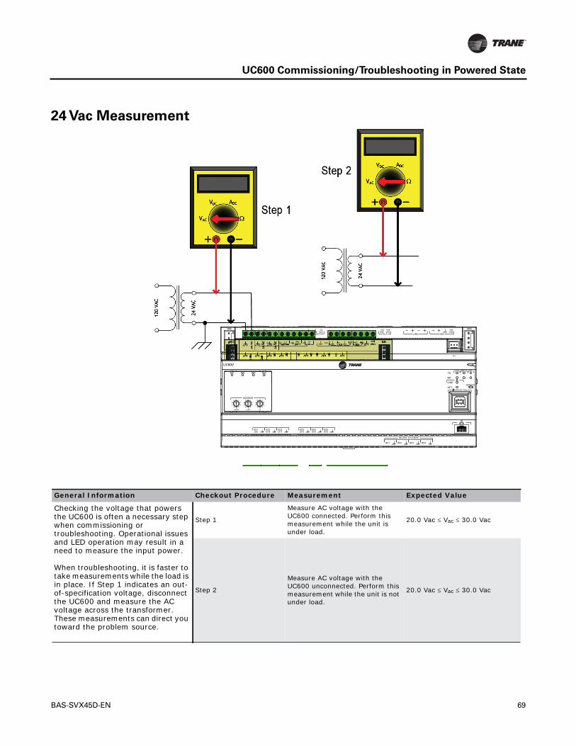
UC600 Commissioning/Troubleshooting in Powered State
24 Vac Measurement
AO6UI14
AO5UI13
AO4UI12
AO3UI11
AO2UI10
AO1UI9
BO4BO3BO2BO1
RELAYS 0.5 A MAX
IMC
1
IMC
P1
UI8UI7UI6UI5UI4UI3UI2UI1
IMC
+24VDC
LINKOUT
+24VDC
+24VDC
OUT
24VAC
MBUSOUT
24VAC
XFMR
24VAC
SERVICE TOOL
SERVICELINK
ACT
IMCMBUSLINK
RX
TX
UC600
ADDRESS0 1
23
456
78
9
x1
0 1
23
456
78
9
x10
0 1
23
456
78
9
x100
BO4BO3BO2BO1
General Information Checkout Procedure Measurement Expected Value
Checking the voltage that powers the UC600 is often a necessary step when commissioning or troubleshooting. Operational issues and LED operation may result in a need to measure the input power. When troubleshooting, it is faster to take measurements while the load is in place. If Step 1 indicates an out-of-specification voltage, disconnect the UC600 and measure the AC voltage across the transformer. These measurements can direct you toward the problem source.
Step 1
Measure AC voltage with the UC600 connected. Perform this measurement while the unit is under load.
20.0 Vac Vac 30.0 Vac
Step 2
Measure AC voltage with the UC600 unconnected. Perform this measurement while the unit is not under load.
20.0 Vac Vac 30.0 Vac
BAS-SVX45D-EN 69

UC600 Commissioning/Troubleshooting in Powered State
Binary Inputs, 24 Vac Detect- Methods 1 or 2
Binary Inputs- Based on Analog Output Connection
General Information and Checkout Procedure Measurement Expected Value
Method 1:Voltage across binary input measured without reference to chassis ground.
Measure AC voltage across the binary input
Vac 0.0 V (state = ON)Vac 24.0 V (state = OFF)
Method 2:Voltage across binary input measured with reference to chassis ground. Any connection with chassis ground symbol can serve as a ground reference for this method.
Measure DC voltage across the binary input
Vac 0.0 V (state = OFF)Vac 24.0 V (state = ON)
General Information Checkout Procedure Measurement Expected Value
The UC600 analog output connections can be configured as binary inputs. This can be used only with dry contact or open collector-type sensors.
Step 1 Measure AC voltage across the binary input
Vac 0.0 VAC voltage will affect further measurement
Step 2 Measure DC voltage across the binary input
Vdc 2.0 V (state = ON)Vdc 2.0 V (state = OFF)
70 BAS-SVX45D-EN

UC600 Commissioning/Troubleshooting in Powered State
Open-collector Based Binary Sensors
Measurement Procedure Expected Value
Measure DC voltage across the binary input Vdc 0.2 V (BJT = ON)UI: Vdc 3.3 V (BJT = OFF)AO: Vdc 22.0 V (BJT = ON)
Open-collector based binary sensors use a bipolar junction transistor (BJT).This is a three-terminal device in which emitter-to-collector current is controlled by base current as theswitching device in place of a relay.The term, open-collector, refers to the collector connectionon the transistor itself. Open-collector circuits are used for their low fatigue rate and quickresponse relative to relay-based outputs.
The circuit within the pulse meter is completed when adding a pull-up resistance and referencevoltage. On the UC600, both universal input (UI) and analog output (AO) circuits add thenecessary resistance and voltage without external parts.
Note: The reference voltage must always be DC.
The voltage across the pulse meter terminals will bounce between Vsat (saturation voltage) ofthe transistor in the pulse meter and theVref (reference voltage) provided by the UI orAO circuitsof the UC600. Most bipolar transistors have a Vsat of less than 0.2 Vdc.
The DMM sampling rate may be too slow to measure pulse meter output transitions.
Note: Check the specifications of the DMM. It may be necessary to use an oscilloscope tomeasure the transition voltages.
BAS-SVX45D-EN 71

UC600 Commissioning/Troubleshooting in Powered State
Voltage Analog Output
Current Analog Output- Methods 1 or 2
Measurement Procedure Expected Value
Measure DC voltage across the voltage termination
Compare to the expected value based on request from controller. This request may be based on an override of the output value.
General Information and Checkout Procedure Measurement Expected Value
Method 1:Shorting the current output- this method leaves the circuit intact, however, it will cause the vast majority of the current to flow through the meter instead of the load (NOTE LOAD RESISTANCE).
Measure DC current across the current termination
Compare expected value based on request from controller. This request may be based on an override of the output value.
Method 2:Measuring current directly- this method is most the typical way to measure current and has the advantage of leaving the load in the loop. However, the circuit must be broken when using this method.
Measure DC current across the current termination
Compare expected value based on request from controller. This request may be based on an override of the output value.
72 BAS-SVX45D-EN

UC600 Commissioning/Troubleshooting in Powered State
Ground Measurements
General Information and Checkout Procedure Measurement Expected Value
Method 1:AC voltage between shield conductors and device chassis ground- the voltage difference between BACnet MS/TP device chassis ground connections should be close to zero. If the voltage difference is greater that 4.0 Vac, there will be marginal communication or intermittent communication problems. If the voltage difference is greater that 7.0 Vac, some devices will no longer communicate.
Measure AC current across the current termination and confirm that only one end of the shield conductor is tied to the earth ground
Vac 2.0 V
Method 2:AC voltage between earth ground and device chassis ground- the chassis ground of the UC600 needs to be connected to earth ground by some route.
Note: Do not assume that the building frame is a valid earth ground.
Measure AC current across the current termination and confirm that only one end of the shield conductor is tied to the earth ground
Vac 4.0 V (Must comply with National Electrical Code™and local electriccodes)
Method 3:AC voltage between case (nominal chassis ground) and device chassis ground connector- in this illustration the connection appears as a short. However, it is possible that the chassis ground connection on the controller may actually be connected to the equipment metal some distance away. Use this measurement method if there are communication issues or input stability problems.
Measure AC voltage across the current termination. For this measurement, confirm that only one end of the shield conductor is tied to the earth ground.
Vac 4.0 V (Must comply with National Electrical trical Code™and local electrical codes) Typically, this should be Vac .0 V
BAS-SVX45D-EN 73

74 BAS-SVX45D-EN
Other Resources
For more detailed information, refer to the following documentation:
• Tracer SC System Controller Installation and Setup (BAS-SVX31)
• BACnet Best Practices andTroubleshooting Guide (BAS-SVX51-EN)
• Tracer Graphical Programming 2 (TGP2) Editor Online Help
• Tracer Graphical Programming (TGP2) Application Guide (BAS-APG008)
• TracerTU Online Help
• TracerTU ServiceTool Getting Started Guide (TTU-SVN01)
• Tracer UC600 Installation Instructions (X39641178-01)
• Tracer XM30 Expansion Module Installation Instructions (X39641148-01)
• Tracer XM32 Expansion Module Installation Instructions (X39641174-01)
• Tracer Expansion Module Installation, Operation, and Maintenance (BAS-SVX046-EN)

Appendix: Protocol Implementation Conformance
Statement (PICS)
This section contains theTracer UC600 BACnet Protocol Implementation Conformance Statement (PICS).The UC600 canbe programmed with a variety of sequence of operations.All data used in the sequences are accessed through the BACnetprotocol.
Standardized Device Profile (Annex L)
Interoperability Building Blocks (Annex K)
BACnet Operator Workstation (B-OWS)
BACnet Building Controller (B-BC)
BACnet Advanced Application Controller (B-AAC)
BACnet Application Specific Controller (B-ASC)
BACnet Smart Sensor (B-SS)
BACnet Smart Actuator (B-SA)
Data Sharing SupportedData Sharing-ReadProperty-B (DS-RP-B)
Data Sharing-ReadPropertyMultiple-B (DS-RPM-B)
Data Sharing-WriteProperty-B (DS-WP-B)
Data Sharing-WritePropertyMultiple-B (DS-WPM-B)
Alarm and Event Management SupportedAlarm and Event-Notification Internal-B (AE-N-I-B)
Alarm and Event-ACKI-B (AE-ACK-B)
Alarm and Event-Alarm Summary-B (AE-ASUM-B)
Alarm and Event-Enrollment Summary-B (AE-ESUM-B)
Alarm and Event-Information-B (AE-INFO-B)
Scheduling SupportedScheduling-Internal-B (SCHED-I-B)
Trending SupportedTrending-viewing and Modifying Trends Internal-B (T-VMT-I-B)
Trending-Automated Trend Retrieval-B (T-ATR-B)
Device Management Description SupportedDevice Management-Dynamic Device Binding-A (DM-DDB-A)
Device Management-Dynamic Device Binding-B (DM-DDB-B)
Device Management-Dynamic Object Binding-B (DM-DOB-B)
Device Management-Device Communication Control-B (DM-DCC-B)
Device Management-TimeSynchronization-B (DM-TS-B)
Device Management-UTC Time Synchronization (DM-UTC-B)
Device Management-Reinitialize Device-B (DM-RD-B)
Device Management-Backup and Restore-B (DM-BR-B)
Device Management-List Manipulation-B (DM-LM-B)
Device Management-Object Creation and Deletion-B (DM-OCD-B)
BAS-SVX45D-EN 75

Appendix: Protocol Implementation Conformance Statement (PICS)
Segmentation Capability
ObjectTypes
Note: For objects that contain the Present_Value and Reliability properties, these properties are only writable whenthe Out_Of_Service property isTrue.
Segmentation SupportedSegmented Requests/ Window Size: 1
Segmented Responses/ Window Size: 1
Table 10. Descriptions and configurations
Object Type Writable Properties Required PropertiesOptional Properties Supported
Ability to Create
Ability to Delete
Analog Input • Object_Name• Description• Out_Of_Service• Present_Value• Reliability• Min_Pres_Value• Max_Pres_Value• COV_Increment• Time_Delay• Notification_Class• High_Limit• Low_Limit• Deadband• Limit_Enable• Event_Enable• Notify_Type
• Object_Identifier• Object_Name• Object_Type• Present_Value• Status_Flags• Event_State• Out_Of_Service• Units
• Description• Reliability• Min_Pres_Value• Max_Pres_Value• COV_Increment• Time_Delay• Notification _Class• High_Limit• Low_Limit• Deadband• Limit_Enable• Event_Enable• Acked_Transitions• Notify_Type• Event_Time_Stamps
Yes Yes, user created objects only
Analog Output
• Object_Name• Description• Out_Of_Service• Present_Value• Reliability• Min_Pres_Value• Max_Pres_Value• Relinquish_Default• COV_Increment• Time_Delay• Notification_Class• High_Limit• Low_Limit• Deadband• Limit_Enable• Event_Enable• Notify_Type
• Object_Identifier• Object_Name• Object_Type• Present_Value• Status_Flags• Event_State• Out_Of_Service• Units• Priority_Array• Relinquish_Default
• Description• Reliability• Min_Pres-Value• Max_Pres_Value• COV_Increment• Time_Delay• Notification _Class• High_Limit• Low_Limit• Deadband• Limit_Enable• Event_Enable• Acked_Transitions• Notify_Type• Event_Time_Stamps
Yes Yes, user created objects only
Analog Value • Object_Name• Description• Out_Of_Service• Present_Value• Reliability• Relinquish_Default• COV_Increment• Time_Delay• Notification_Class• High_Limit• Low_Limit• Deadband• Limit_Enable• Event_Enable• Notify_Type
• Object_Identifier• Object_Name• Object_Type• Present_Value• Status_Flags• Event_State• Out_Of_Service• Units
• Description• Reliability• Priority_Array• Relinquish_Default• COV_Increment• Time_Delay• Notification_Class• High_Limit• Low_Limit• Deadband• Limit_Enable• Event_Enable• Acked_Transitions• Notify_Type• Event_Time_Stamps
Yes Yes, user created objects only
76 BAS-SVX45D-EN

Appendix: Protocol Implementation Conformance Statement (PICS)
Binary Input • Object_Name• Description• Out_Of_Service• Inactive_Text• Active_Text• Present_Value• Reliability• Change_Of_State_Count• Elapsed_Active_Time• Time_Delay• Notification_Class• Alarm_Value• Event_Enable• Polarity• Notify_Type
• Object_Identifier• Object_Name• Object_Type• Present_Value• Status_Flags• Event_State• Out_Of_Service• Polarity
• Description• Inactive_Text• Active_Text• Change_Of_State_Time• Change_Of_State_Count• Time_Of_State_Count_Reset• Elapsed_Active_Time• Time_Of_Active_Time_Reset• Time_Delay• Notification_Class• Alarm_Value• Event_Enable• Acked_Transitions• Notify_Type• Event_Time_Stamps• Reliability
Yes Yes, user created objects only
Binary Output
• Object_Name• Description• Out_Of_Service• Inactive_Text• Active_Text• Present_Value• Reliability• Change_Of_State_Count• Elapsed_Active_Time• Minimum_On_Time• Minimum_Off_Time• Relinquish_Default• Time_Delay• Notification_Class• Event_Enable• Notify_Type• Polarity
• Object_Identifier• Object_Name• Object_Type• Present_Value• Status_Flags• Event_State• Out_Of_Service• Polarity• Priority_Array• Relinquish_Default
• Description• Inactive_Text• Active_Text• Change_Of_State_Time• Change_Of_State_Count• Time_Of_State_Count_Reset• Elapsed_Active_Time• Time_Of_Active_Time_Reset• Minimum_On_Time• Minimum_Off_Time• Time_Delay• Notification_Class• Feedback_Value• Event_Enable• Acked_Transitions• Notify_Type• Event_Time_Stamps• Reliability
Yes Yes, user created objects only
Binary Value • Object_Name• Description• Out_Of_Service• Inactive_Text• Active_Text• Present_Value• Reliability• Change_Of_State_Count• Elapsed_Active_Time• Minimum_On_Time• Minimum_Off_Time• Relinquish_Default• Time_Delay• Notification_Class• Alarm_Value• Event_Enable• Notify_Type• Alarm_Value
• Object_Identifier• Object_Name• Object_Type• Present_Value• Status_Flags• Event_State• Out_Of_Service
• Description• Inactive_Text• Active_Text• Change_Of_State_Time• Change_Of_State_Count• Time_Of_State_Count_Reset• Elapsed_Active_Time• Time_Of_Active_Time_Reset• Priority_Array• Relinquish_Default• Minimum_On_Time• Minimum_Off_Time• Time_Delay• Notification_Class• Alarm_Value• Event_Enable• Acked_Transitions• Notify_Type• Event_Time_Stamps• Reliability
Yes Yes, user created objects only
Calendar • Object_Name• Description• Date_List
• Object_Identifier• Object_Name• Object_Type• Present_Value• Date_List
• Description Yes Yes, user created objects only
Table 10. Descriptions and configurations (continued)
Object Type Writable Properties Required PropertiesOptional Properties Supported
Ability to Create
Ability to Delete
BAS-SVX45D-EN 77

Appendix: Protocol Implementation Conformance Statement (PICS)
Device • Object_Name• Location• Description• APDU_Segment_Timeout• APDU_Timeout• Number_Of_APDU_Retries• Max_Master• Max_Info_Frames• Backup_Failure_Timeout
• Object_Identifier• Object_Name• Object_Type• System_Status• Vendor_Name• Vendor_Identifier• Model_Name• Firmware_Revision• Application_Software_Version• Protocol_Version• Protocol_Revision• Protocol_Services_Supported• Protocol_Object_Types_Supported• Object_List• Max_APDU_Length_Accepted• Segmentation_Supported• APDU_Timeout• Number_Of_APDU_Retries• Device_Address_Binding• Database_Revision
• Location• Description• Max_Segments_Accepted• APDU_Segment_Timeout• Max_Master• Max_Info_Frames• Local_Time• Local_Date• UTC_Offset• Daylight_Savings_Status• Configuration_Files• Last_Restore_Time• Backup_Failure_Timeout• Profile_Name
No No
Event Enrollment Object
• Object_Name• Notify_Type• Event_Parameters• Object_Property_Reference• Event_Enable• Notification_Class
• Object_Identifier• Object_Name• Object_Type• Event_Type• Notify_Type• Event_Parameters• Object_Property_Reference• Event_State• Event_Enable• Acked_Transitions• Notification_Class• Event_Time_Stamps
• None Yes Yes, user created objects only
Event Log Object
• Object_Name• Enable• Stop_When_Full• Record_Count
• Object_Identifier• Object_Name• Object_Type• Status_Flags• Event_State• Enable• Stop_When_Full• Buffer Size• Log_Buffer• Record_Count• Totla_Record_Count
• None No No
Multistate Input
• Object_Name• Description• State_Text• Out_Of_Service• Present_Value• Reliability• Time_Delay• Notification_Class• Alarm_Values• Fault_Values• Number_Of_States• Event_Enable• Notify_Type
• Object_Identifier• Object_Name• Object_Type• Present_Value• Status_Flags• Event_State• Out_Of_Service• Number_Of_States
• State_Text• Description• Reliability• Time_Delay• Notification_Class• Alarm_Values• Fault_Values• Event_Enable• Acked_Transitions• Notify_Type• Event_Time_Stamps
Yes Yes, user created objects only
Multistate Output
• Object_Name• Description• State_Text• Out_Of_Service• Present_Value• Reliability• Relinquish_Default• Time_Delay• Notification_Class• Event_Enable• Number_Of_States• Notify_Type
• Object_Identifier• Object_Name• Object_Type• Present_Value• Status_Flags• Event_State• Out_Of_Service• Number_Of_States• Priority_Array• Relinquish Default
• State_Text• Description• Reliability• Time_Delay• Notification_Class• Feedback_Values• Event_Enable• Acked_Transitions• Notify_Type• Event_Time_Stamps
Yes Yes, user created objects only
Table 10. Descriptions and configurations (continued)
Object Type Writable Properties Required PropertiesOptional Properties Supported
Ability to Create
Ability to Delete
78 BAS-SVX45D-EN

Appendix: Protocol Implementation Conformance Statement (PICS)
BACnet Protocol
Data Link Layer Options
Multistate Value
• Object_Name• Description• Number_Of_States• State_Text• Out_Of_Service• Present_Value• Reliability• Relinquish_Default• Time_Delay• Notification_Class• Alarm_Values• Fault_Values• Event_Enable• Notify_Type
• Object_Identifier• Object_Name• Object_Type• Present_Value• Status_Flags• Event_State• Out_Of_Service• Number_Of_States
• State_Text• Description• Priority_Array• Reliability• Relinquish_Default• Time_Delay• Notification_Class• Alarm_Values• Fault_Values• Event_Enable• Acked_Transitions• Notify_Type• Event_Time_Stamps
Yes Yes, user created objects only
Notification Class
• Object_Name• Priority• Ack_Required• Recipient_List
• Object_Identifier• Object_Name• Object_Type• Notification_Class• Priority• Ack_Required• Recipient_List
• None Yes Yes, user created objects only
Schedule • Object_Name• Description• Present_Value• Effective_Period• Weekly_Schedule• Exception_Schedule• Schedule_Default• List_Of_Object_Property
_References• Priority_For_Writing• Out-Of_Service
• Object_Identifier• Object_Name• Object_Type• Present_Value• Effective_Period• Weekly_Schedule• Exception_Schedule• Schedule_Default• List_Of_Object_Property
_References• Priority_For-Writing• Status_Flags• Reliability• Out-Of-Service
• Description Yes Yes, user created objects only
Trend • Object_Name• Enable• Start_Time• Stop_Time• Log_DeviceObjectProperty• Log_Interval• Stop_When_Full• Buffer_Size• Record_Count• Notification_Threshold• Notification_Class• Event_Enable• Notify_Type
• Object_Identifier• Object_Name• Object_Type• Enable• Stop_When_Full• Buffer_Size• Log_Buffer• Record_Count• Total_Record_Count• Event_State• Logging_Type• Status_Flags
• Start_Time• Stop_Time• Log_Device_Object_Property• Log_Interval• Notification_Threshold• Records_Since_Notification• Last_Notify_Record• Notification_Class• Event_Enable• Acked_Transitions• Event_Time_Stamps• Notify_Type• Event_Time_Stamps
Yes Yes, user created objects only
Data Link Layer OptionsBACnet IP, (Annex J)
BACnet IP, (Annex J), Foreign Device
ISO 8802-3, Ethernet (Clause 7)(10Base2, 10Base5, 10BaseT, Fiber)
ANSI/ATA 878.1, 2.5 Mb ARCNET (Clause 8)
ANSI/ATA 878.1, RS-485 ARCNET (Clause 8), Baud Rate(s)
MS/TP Master (Clause 9), Baud Rate(s): 9600, 19200, 38400, and 76800
MS/TP Slave (Clause 9), Baud Rate(s)
Point-to-Point, EIA 232 (Clause 10), Baud Rate(s): 9600, 19200, 38400
Point-to-Point, Modem (Clause 10), Baud Rate(s): 9600, 19200, 38400
Table 10. Descriptions and configurations (continued)
Object Type Writable Properties Required PropertiesOptional Properties Supported
Ability to Create
Ability to Delete
BAS-SVX45D-EN 79
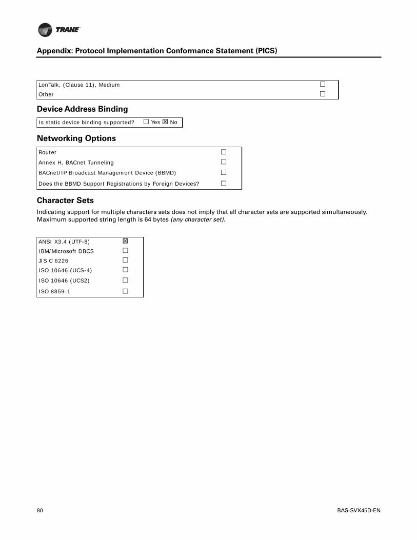
Appendix: Protocol Implementation Conformance Statement (PICS)
Device Address Binding
Networking Options
Character Sets
Indicating support for multiple characters sets does not imply that all character sets are supported simultaneously.Maximum supported string length is 64 bytes (any character set).
LonTalk, (Clause 11), Medium
Other
Is static device binding supported? Yes No
Router
Annex H, BACnet Tunneling
BACnet/IP Broadcast Management Device (BBMD)
Does the BBMD Support Registrations by Foreign Devices?
ANSI X3.4 (UTF-8)
IBM/Microsoft DBCS
JIS C 6226
ISO 10646 (UCS-4)
ISO 10646 (UCS2)
ISO 8859-1
80 BAS-SVX45D-EN

Declaration of CE Conformity
The manufacturer hereby declares that the product:
Conforms to the following standards or other normative documents:
Manufacturer name: Trane
Manufacturer address: 3600 Pammel Creek RoadLaCrosse, WI 54601USA
Product name: Tracer™ UC600 Unit Controller
Model numbers: X13651548
Electromagnetic Emission:EN61326-1:2006
Electrical equipment for measurement, control, and laboratory use—EMC requirements, part 1: General Requirements
(by Council Directive 2004/108/EEC)EN55022:2006 (CISPR 22:2005+A1:2005) Radiated Emissions
Class B Limit (30 MHz—1000 MHz, 1 GHz—2 GHz)
EN55022:2006 (CISPR 22:2005+A1:2005) Radiated Emissions
150 kHz—30 MHz
Electromagnetic Immunity for Industrial: EN61326-1:2006
(by Council Directive 89/336/EEC)EN61000-4-2: 1995+A1: 1998+A2:2001 Electrostatic Discharge (ESD)
8 kV air, 4 kV contact
EN61000-4-3: 2002 Radiated Fields10 V/m, 80 MHz—1000 MHz3 V/m, 1.4 GHz—2.0 GHz1 V/m, 2.0 GHz—2.7 GHz
EN61000-4-4: 2004 Fast TransientsI/O port, 1 kVAC inputs and output ports, 2 kV
EN61000-4-5: 1995+A1: 2001 Surge Transients AC input ports (L/L), differential mode, 1 kV
EN61000-4-6: 1996+A1: 2001 Conducted Disturbance 3 V, 0.15 MHz—80 MHz
EN61000-4-8: 1993+A1: 2001 Power Frequency Magnetic Field 30 A/m, 50 Hz
EN61000-4-11: Second Edition: 2004 Voltage Dips and Interruptions
0% Vnom, 1 cycle; 70% Vnom, 25 cycle; 40% Vnom, 10 cycle; 0% Vnom, 250 cycle
Where and When Issued: Electromagnetic Emission 10/01/2010
Electromagnetic Immunity 10/13/2010
Mark of Compliance: European ContactSociete Trane (Epinal, France)1, rue des Ameriques, B.P. 6F-88191 Golbey Cedex, FrancePhone: (33) 329.31.73.00Fax: (33) 329.81.24.98
This document validates CE conformity of the Tracer UC600 Unit Controller

Trane optimizes the performance of homes and buildings around the world. A business of Ingersoll Rand, theleader in creating and sustaining safe, comfortable and energy efficient environments, Trane offers a broadportfolio of advanced controls and HVAC systems, comprehensive building services, and parts. For moreinformation, visit www.Trane.com.
Trane has a policy of continuous product and product data improvement and reserves the right to change design and specifications without notice.
We are committed to using environmentally
conscious print practices that reduce waste.
© 2012Trane All rights reserved
BAS-SVX45D-EN 15 Dec 2012
Supersedes BAS-SVX45C-EN (31 Jul 2012)