Installation, Operating & Maintenance Manual - Honeywell · Installation, Operating & Maintenance...
22
Lidec Level Switch Series L20-70 D Installation, Operating & Maintenance Manual SAS au Capital de 2 158 244 €- 444 871 933 R.C.S. Bourges - APE : 2651B Headquarter : 9, rue Isaac Newton - 18000 Bourges - France
Transcript of Installation, Operating & Maintenance Manual - Honeywell · Installation, Operating & Maintenance...

Lidec Level Switch
Series L20-70 D
Installation, Operating & Maintenance Manual
SAS au Capital de 2 158 244 € - 444 871 933 R.C.S. Bourges - APE : 2651B Headquarter : 9, rue Isaac Newton - 18000 Bourges - France

Lidec Level Switch Installation, Operating & Maintenance Manual
Series L20-70 D
1st Edition Released February 2013

TABLE OF ONTENTS
1. UNPACKING AND INSPECTION .................................................................................................... 4
2. STORAGE ....................................................................................................................................... 4
3. OPERATING PRINCIPE ................................................................................................................. 4
4. OVERALL VIEW AND DIMENSIONS .............................................................................................. 4
5. TECHNICAL DATA ......................................................................................................................... 5
6. INSTALLATION ............................................................................................................................... 6
7. OUTPUT SETTING ......................................................................................................................... 7
8. ELECTRICAL CONNECTIONS ....................................................................................................... 8
8.1. Connection diagram of probe without test switch (single box)................................................... 8
8.2. Connection diagram of probe with test switch (dual box) .......................................................... 8
8.3. Supply voltage 16 to 28 Vdc ..................................................................................................... 9
8.4. Cable definition ........................................................................................................................ 9
8.5. Special precautions for the intrinsically safe installation Ex ia ................................................... 9
8.6. Connection diagram ............................................................................................................... 10
9. LEVEL ALARM ADJUSTMENT (only for vertical installation) ........................................................ 11
10. TEST ............................................................................................................................................ 11
11. TROUBLE SHOOTING GUIDE .................................................................................................... 11
Annex A ............................................................................................................................................. 12

Doc No: NT406E – Revision 09 – ENG Lidec Level Switch Series 91-92 Installation, Operating & Maintenance Manual
4
1. UNPACKING AND INSPECTION ● Carefully unpack and inspect the equipment; in case of damage, file proper reserves with carrier.
● The identification of the instrument is indicated on the connection head.
2. STORAGE The material should be stored in covered area, in the original packing and protected.
The storage temperature : - 40 to +80°C
3. OPERATING PRINCIPE The level detector LIDEC is detecting the free liquid presence as high or low level alarm with a current output (18/6 mA) in power supply loop or a dry contact output. The installation of the probe can be either horizontal or vertical.
The operating principle is based on the absorption of mechanical waves from the sensitive part of the metallic probe in case of contact with liquid. A piezo-electrical ceramic generates these waves then detects their amplitude after reflection on the probe extremity. The detected absorption causes either a variation of the consumption current, from 18 to 6 mA or reverse, or the switching of the relay.
This equipment offers a reliable fully fail safe operating system. The alarm occurs in following conditions:
● Liquid detection
● Electronic and/or sensor failure
● Power supply failure
In addition, in the dual box type variation are placed one test switch per channel, allowing, by using a test magnet, to check the efficiency of the alarm sequence in remote conditions, without access to the probe and without opening the enclosure. When activated, the test switch simulates the detection of liquid, and starts the alarm sequence.
4. OVERALL VIEW AND DIMENSIONS Refer to drawings : M32017 Lidec 20-70 DR, Polyester box, Relay output
M31999 Lidec 20-70 D, Polyester box, Current output
M36114 Lidec 20-70 DR, Stainless steel box, Relay output
M34227 Lidec 20-70 D, Stainless steel box, Current output
M34229 Lidec 20-70 D, dual stainless steel box with test, Current output
NOTE: Due to that principle, the probe must not be paint, it must be cleaned periodically when used with viscous liquid.

Doc No: NT406E – Revision 09 – ENG Lidec Level Switch Series 91-92 Installation, Operating & Maintenance Manual
5
5. TECHNICAL DATA The different variations of Lidec L20-70 D are defined according to the following table :
Current Output Relay Output
Length of cable between probe and electronic box 30m max
L20-70 D L20-70 DR
● Power Supply: 16 to 28 VDC (24 VDC nominal)
● Power consumption: 0.6 W
● Output configuration: COM/NO/NC dry contact contact rating 5 A/28 Vdc
Current loop variation 18 / 6 mA
● Level alarm (factory pre set):
vertical mounting = 5 mm above the low point of the probe.
Horizontal mounting = axis of the probe.
● Accuracy: ± 2mm
● Hysteresis: < 4mm
● Electrical connection: terminal connection for maxi 1,5 mm2 wire, and maxi cable
Æ 12 or 14 mm with polyester box
Æ 14.5 mm with stainless steel box, single or dual
● Weatherproof protection: IP66 : Polyester remote electronics box
IP66/67: Stainless steel remote electronics box, single or dual
IP68 : probe up to 50m depth, checked during 20 days
● Operating safety: Positive safety when ST1 so that output is 18 mA or relay On out of alarm
● Operating Temperature: -25 to +70°C (housing)
up to 70°C (probe)
● Intrinsic Safety: II 1 G D Ex ia IIC or IIB T6 or T5 or T4 Ga (see also § 8.4) Ex ia IIIC T80°C or T95°C or T130°C Da IP6x

Doc No: NT406E – Revision 09 – ENG Lidec Level Switch Series 91-92 Installation, Operating & Maintenance Manual
6
6. INSTALLATION ● Both horizontal and vertical installations are possible.
● Two fixing holes diameter 7 mm for the probes' bracket, four fixing holes diam. 4.5 mm for the polyester box or 13 mm for the stainless steel box, two holes diam. 8.5 for the dual box.
INSTALLATION WITH FLEXIBLE CONDUIT
CAUTION: If any kind of works is to be carried out around the probe, it is necessary to protect it against shocks, sandblasting, painting etc…

Doc No: NT406E – Revision 09 – ENG Lidec Level Switch Series 91-92 Installation, Operating & Maintenance Manual
7
7. OUTPUT SETTING ● ST4 and ST5 are factory preset
● ST1 :
18 mA out of liquid
No jump on L20-70D See chapter 8.2
No jump on L20-70D

Doc No: NT406E – Revision 09 – ENG Lidec Level Switch Series 91-92 Installation, Operating & Maintenance Manual
8
8. ELECTRICAL CONNECTIONS
8.1. Connection diagram of probe without test switch (single box)
8.2. Connection diagram of probe with test switch (dual box)
NOTE: Make sure to respect the correspondence between probe and electronic board: "L" (low alarm) probe to be connected on "L" board; "H" (high alarm) probe to be connected on "H" board.
CAUTION: The connections are to be made with power switched off.
Brown
Blue
Red
From probe

Doc No: NT406E – Revision 09 – ENG Lidec Level Switch Series 91-92 Installation, Operating & Maintenance Manual
9
8.3. Supply voltage 16 to 28 Vdc
8.4. Cable definition Multiwire screened shielded cable :
● Composition : 2-wires cable for current loop connection (polyester or stainless steel box); 4 wires cable with relay output connection (polyester or stainless steel box), 4-wires cable with current loop connection (dual stainless steel box with test),
● Diameter of the cable : see § 5 Technical data
8.5. Special precautions for the intrinsically safe installation Ex ia
NOTE: - Make sure to respect the intrinsic safety requirements (see chapter 8.5)
- The screen must be connected to ground on the voltage supply side, and not on the Lidec enclosure.
Brown
Blue
Red
Magnetic test switch From probe
NOTE: LIDEC transmitter is certified II 1 G D Ex ia IIC or IIB T6 or T5 or T4 Ga
Ex ia IIIC T80°C or T95°C or T130°C Da IP6X under certificate n° LCIE 02 ATEX 6181X and IECEx LCI 11.0001 X, meaning that it must be
associated to an intrinsically safe certified device, complying with the transmitter's intrinsic safety parameters.

Doc No: NT406E – Revision 09 – ENG Lidec Level Switch Series 91-92 Installation, Operating & Maintenance Manual
10
● Ratings on power supply line (terminal B1) :
Class U max I max P max L int. C int. Ambient T°C Ex ia IIC T6 28V 100mA 0.78W 0 50nF -25 to +40°C Ex ia IIC T5 28V 100mA 0.78W 0 50nF -25 to +55°C Ex ia IIC T4 28V 100mA 0.78W 0 50nF -25 to +70°C
Ex ia IIC T5 28V 120mA 0.84W 0 50nF -25 to +40°C Ex ia IIC T4 28V 120mA 0.84W 0 50nF -25 to +70°C
Ex ia IIB T5 28V 200mA 1.4W 0 50nF -25 to +40°C Ex ia IIB T4 28V 200mA 1.4W 0 50nF -25 to +70°C
● Ratings on dry contact line (terminal B3) : U max £ 28 Vdc; L int. = C int. = 0
The result of such association is an intrinsically safe system, which must be certified. The certification is the responsibility of the provider of the associated device.
As consequence, a suitable Zener barrier must be installed in Safe Area, to be inserted in line between LIDEC and power supply / acquisition device on B1, and in line between LIDEC and alarm unit on B3 when used.
8.6. Connection diagram
Doc No: NT406E – Revision 09 – ENG Lidec Level Switch Series 91-92 Installation, Operating & Maintenance Manual
11
9. LEVEL ALARM ADJUSTMENT (only for vertical installation) The potentiometers with red varnish are factory pre-set, and not to be modified.
The LIDEC are factory pre-set 5 mm above the low point of the probe for water level detection.
The "SENS" potentiometer situated on the circuit board allows adjustment of the sensitivity related to the liquid wave absorption properties, and as consequence to adjust lightly the alarm level.
10. TEST ● Check the electric connection according to the diagram § 8.6.
● Operating cycle test: check the contact relay releasing or the current loop variation by tightening the probe between fingers to simulate the liquid absorption.
● For the LIDEC with dual box and test switches, the alarm sequence is checked by approaching a magnet on top of the housing, successively in the area proper to each channel: the relevant alarm should be activated immediately.
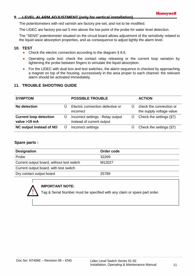
11. TROUBLE SHOOTING GUIDE
SYMPTOM POSSIBLE TROUBLE ACTION
No detection Ü Electric connection defective or incorrect
Ü check the connection or the supply voltage value
Current loop detection value >19 mA
Ü Incorrect settings : Relay output instead of current output
Ü Check the settings (§7)
NC output instead of NO Ü Incorrect settings Ü Check the settings (§7)
Spare parts :
Designation Order code Probe 32269 Current output board, without test switch M12027 Current output board, with test switch Dry contact output board 25789
IMPORTANT NOTE: Tag & Serial Number must be specified with any claim or spare part order.

Doc No: NT406E – Revision 09 – ENG Lidec Level Switch Series 91-92 Installation, Operating & Maintenance Manual
12
Annex A

Doc No: NT406E – Revision 09 – ENG Lidec Level Switch Series 91-92 Installation, Operating & Maintenance Manual
13

Doc No: NT406E – Revision 09 – ENG Lidec Level Switch Series 91-92 Installation, Operating & Maintenance Manual
14

Doc No: NT406E – Revision 09 – ENG Lidec Level Switch Series 91-92 Installation, Operating & Maintenance Manual
15

Doc No: NT406E – Revision 09 – ENG Lidec Level Switch Series 91-92 Installation, Operating & Maintenance Manual
16

Doc No: NT406E – Revision 09 – ENG Lidec Level Switch Series 91-92 Installation, Operating & Maintenance Manual
17

Doc No: NT406E – Revision 09 – ENG Lidec Level Switch Series 91-92 Installation, Operating & Maintenance Manual
18

Doc No: NT406E – Revision 09 – ENG Lidec Level Switch Series 91-92 Installation, Operating & Maintenance Manual
19
Doc No: NT406E – Revision 09 – ENG Lidec Level Switch Series 91-92 Installation, Operating & Maintenance Manual
20
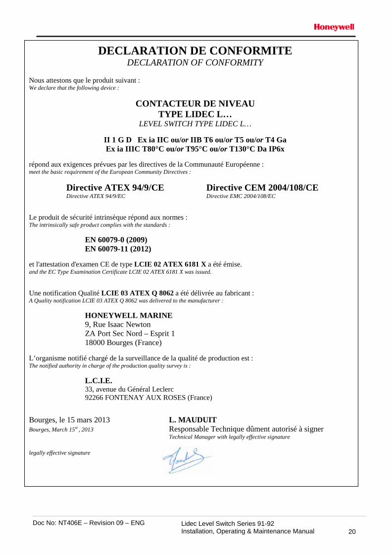
DECLARATION DE CONFORMITE DECLARATION OF CONFORMITY
Nous attestons que le produit suivant : We declare that the following device :
CONTACTEUR DE NIVEAU TYPE LIDEC L…
LEVEL SWITCH TYPE LIDEC L…
II 1 G D Ex ia IIC ou/or IIB T6 ou/or T5 ou/or T4 Ga Ex ia IIIC T80°C ou/or T95°C ou/or T130°C Da IP6x
répond aux exigences prévues par les directives de la Communauté Européenne : meet the basic requirement of the European Community Directives :
Directive ATEX 94/9/CE Directive CEM 2004/108/CE Directive ATEX 94/9/EC Directive EMC 2004/108/EC
Le produit de sécurité intrinsèque répond aux normes : The intrinsically safe product complies with the standards :
EN 60079-0 (2009) EN 60079-11 (2012)
et l'attestation d'examen CE de type LCIE 02 ATEX 6181 X a été émise. and the EC Type Examination Certificate LCIE 02 ATEX 6181 X was issued. Une notification Qualité LCIE 03 ATEX Q 8062 a été délivrée au fabricant : A Quality notification LCIE 03 ATEX Q 8062 was delivered to the manufacturer :
HONEYWELL MARINE 9, Rue Isaac Newton ZA Port Sec Nord – Esprit 1 18000 Bourges (France)
L’organisme notifié chargé de la surveillance de la qualité de production est : The notified authority in charge of the production quality survey is :
L.C.I.E. 33, avenue du Général Leclerc 92266 FONTENAY AUX ROSES (France)
Bourges, le 15 mars 2013 L. MAUDUIT Bourges, March 15st , 2013 Responsable Technique dûment autorisé à signer Technical Manager with legally effective signature legally effective signature


Honeywell Marine SAS 9, Rue Isaac Newton 18000 Bourges France Tel + 33 (0) 2 48 23 79 01 Fax + 33 (0) 2 48 23 79 03 E-mail: [email protected] www.honeywellprocess.com
NT406E-L20 70 D-rev09-ENG February 2013 © 2013 Honeywell International Inc.