
Temporary Lifelines - Textile Lifelines - Transportable Lifelines EN795

GEMTOR ™ GEMTOR, INC.
...when your life is on the line™ One Johnson Avenue Matawan, NJ 07747 732-583-6200 800-405-9048 Fax 732-290-9391
OWNER'S MANUAL
Installation, Operating, Inspection and Maintenance Instructions
Gemtor Temporary Horizontal Lifeline System with Unitensioner
Model # HL2-60 - Complete Temporary Wire Rope Horizontal Lifeline System
Warning
You must read and fully understand all instructions, or have all instructions explained to you, before attempting to use this device. Equipment must not be installed, operated or inspected by anyone who does not understand this Owner's Manual. Failure to observe these instructions could result in serious injury or death. Careless or improper use of this equipment can result in serious injury or death. Training and instruction review should be conducted before initial use and repeated periodically and without exposing the trainee to a fall hazard. Proper training should also cover the limitations of this product. If you have any questions regarding these instructions or need additional copies, call Gemtor toll free at 800-405-9048.
This user instruction manual is not a substitute for a
Comprehensive training program.
IMPORTANT: THESE INSTRUCTIONS SHOULD BE KEPT WITH THE DEVICE AT ALL TIMES.

Rev. 8-8-13
© Copyright 1998-2013 Gemtor, Inc.
Page 2 of 16
IMPORTANT OSHA INFO (subpart M - 1926.502(d)(8)) Horizontal lifelines shall be designed, installed and used under the supervision of a qualified person, as part of a complete personal fall arrest system, which maintains a safety factor of at least two.
IMPORTANT When using any lifeline, regardless of configuration or manufacture, it is important to realize that there are some definite limitations on use that must be considered, and definite work practices that must be followed. Lifelines are flexible anchorages that allow a worker to be tied-off at any point along either a vertical or horizontal span. Unlike a fixed anchorage, lifelines are susceptible to substantial movement, elongation and deflection when subjected to the forces of a fall. These inherent characteristics of a lifeline must be considered when a worker is planning his fall protection system to ensure that he cannot strike a lower level or be otherwise injured.
When more than one worker shares a lifeline* extreme care must be taken to ensure that if one worker falls, lifeline movement, elongation and deflection do not adversely affect the other workers. Specifically, a qualified/competent person must ensure that the system is rigged and the workers are positioned in such a manner so that if one worker falls, it would not cause one or more other workers to fall. To reduce the possibility of serious injury, if more than one worker is within the same segment of a multiple man horizontal lifeline system, the system must be rigged so that lanyard length is greater than potential lifeline deflection and potential free fall distance is minimized.
*Note: OSHA does not allow more than one worker on a vertical lifeline. Gemtor
recommends that only one worker be tied-off between supports on any lifeline.
GENERAL DESCRIPTION The Gemtor Horizontal Wire Rope Lifeline System (HL2-60) is designed for use as a temporary, horizontal, fixed safety and grab line that can support the fall of a worker attached to the system. It is used in high places such as transmission towers, shipyards, buildings, bridges, and dams, as well as on construction sites. The HL2-60 must be suspended between two approved anchor points. (Fig. 1 & 2) When a worker, who is wearing an approved Full-Body Harness with a Lanyard (without shock absorber), attaches himself to the HL2-60, he is able to move freely along the length of the lifeline to perform his tasks. In the event the worker loses his footing, or otherwise falls, the horizontal lifeline, in combination with the lanyard and harness, will arrest the fall and reduce the possibility of the worker suffering a serious injury. In order to function properly, the horizontal lifeline must be sufficiently taut. Under proper tension, the HL2-60 allows the worker's lanyard or other slide piece to move easily along the lifeline. The HL2-60 can function as a steadying line for a worker as well as a tie off lifeline. In the event of a fall, the falling worker generates many times his weight in the force exerted on the lifeline. The wire rope Unitensioner®, the basic

Rev. 8-8-13
© Copyright 1998-2013 Gemtor, Inc.
Page 3 of 16
GENERAL DESCRIPTION (continued)
component of the HL2-60, significantly reduces the force of a fall as applied to both the falling worker and the lifeline anchorages through deflection, elongation and friction. To safely compensate for deflection, lifeline elongation, the worker’s height and lanyard length, the HL2 must be properly rigged at the correct height (see Fig. 1 & 2 on pages 4 & 5).
SYSTEM COMPONENTS The Gemtor HL2-60 consists of the following approved components: (Fig. 3)
Unitensioner®
5/16" diameter wire rope lifeline with combination clamp and thimble and wire rope clamp
Two (2) webbing anchorage slings (6 feet)
Three (3) automatic locking carabiners
Two (2) adjustable length web lanyards
Carrying bag The Gemtor HL2-60 comes completely assembled and ready for use

Rev. 8-8-13
© Copyright 1998-2013 Gemtor, Inc.
Page 4 of 16
WITH WEB LANYARD
FIG. 1
MC - MINIMUM CLEARANCE A - LIFELINE DEFLECTION B - LANYARD W - AVERAGE HEIGHT OF WORKER 2 FEET - SAFETY MARGIN
LANYARD 3 feet HMIN. = 4 feet
LANYARD 5 feet HMIN. = 6 feet
MC=A+B+W+2
EXAMPLE
DEFLECTION - 4 feet *LANYARD - 3 feet AVERAGE HEIGHT OF WORKER - 6 feet SAFETY MARGIN - 2 feet
MC=4+3+6+2 = 15 feet
* LANYARD WITHOUT SHOCK ABSORBER

Rev. 8-8-13
© Copyright 1998-2013 Gemtor, Inc.
Page 5 of 16
WITH SELF-RETRACTING LIFELINE
Fig. 2
MC - MINIMUM CLEARANCE A - LIFELINE DEFLECTION B - DISTANCE BETWEEN HARNESS D-RING AND ANCHOR POINT OF THE LIFELINE + 2 feet W - AVERAGE HEIGHT OF WORKER 2 feet - SAFETY MARGIN
MC=A+B+W+2

Rev. 8-8-13
© Copyright 1998-2013 Gemtor, Inc.
Page 6 of 16
GEMTOR HORIZONTAL CABLE LIFELINE SYSTEM HL2-60
FIG 3
FIG 4
WIRE ROPE UNITENSIONER (TOP VIEW)

Rev. 8-8-13
© Copyright 1998-2013 Gemtor, Inc.
Page 7 of 16
THE UNITENSIONER®
The Unitensioner®, incorporated in the lifeline system (Fig. 3 & 4), performs the following four functions:
Tightens the lifeline
Maintains and controls the tension on the lifeline
Absorbs kinetic energy of the fall
Permits adjustment to the HL2-60 system The Unitensioner® consists of the following parts (Fig. 4):
Housing (1)
Drum with wire rope (2) and pulley
Axle (3)
Mechanism A (maintains proper lifeline tension) (4)
Lever (5) drives Mechanism A
Mechanism B (absorbs energy of fall) (6)
Red Push button on Mechanism B (disengages energy absorber) (7)
Eye swivel (8) Once correctly installed, the Wire Rope Unitensioner® maintains the proper tension in the HL2-60 and, in a ready state, assures the significant reduction of forces resulting from a fall. The Wire Rope Unitensioner® has the dual function of providing consistent line tension and preparedness should a fall occur. When a fall occurs, the force of the falling worker pulls on the lanyard tied off on the horizontal lifeline. The lifeline in turn transfers the force to the Wire Rope Unitensioner® at the attachment pulley which transfers the force to Mechanism B (6), (the energy absorber), by pulling the wire rope from the drum (2) and driving the axle (3). Mechanism B acts as a brake by resisting the turning of the axle and absorbing the energy, thus reducing the force at the anchor points of the lifeline system. The controlled energy absorption also eliminates rebounding of the fallen worker.
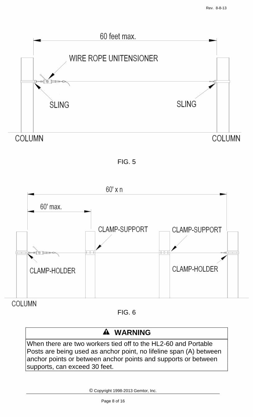
ANCHORS Existing columns can be used as anchor points (Fig. 5 & 6). Maximum distance between two anchor points cannot exceed 60 feet. If the work area to be traveled exceeds 60 feet intermediate support of the lifeline is required. When additional column(s) exist between anchor points separated by more than 60 feet, special lifeline supporting clamps must be affixed to the column(s) for the required lifeline support. When columns are not available to be used as anchor points, temporary anchor point posts must be installed to provide proper horizontal lifeline anchorage. When possible, it is best to install the temporary horizontal lifeline system and portable posts for anchorage before beams are lifted and fastened in construction (Fig. 7). Should the distance between portable anchor posts exceed 60 feet, intermediate post(s) must be installed (Fig. 7).
Rev. 8-8-13
© Copyright 1998-2013 Gemtor, Inc.
Page 8 of 16
FIG. 5
FIG. 6
WARNING
When there are two workers tied off to the HL2-60 and Portable Posts are being used as anchor point, no lifeline span (A) between anchor points or between anchor points and supports or between supports, can exceed 30 feet.

Rev. 8-8-13
© Copyright 1998-2013 Gemtor, Inc.
Page 9 of 16

Rev. 8-8-13
© Copyright 1998-2013 Gemtor, Inc.
Page 10 of 16
Minimum Distance from the HCLS to the Walkway (Hmin) Calculation For proper calculation of the minimum distance to the walkway, please follow the formula and tables below: Calculations are based on a 2 foot free fall.
Minimum Clearance “MC” & Minimum Height Hmin
Table 1
30 Foot Horizontal Lifeline
Lanyard length
One Worker Two Workers
Hmin from walkway to hor. lifeline
MC- Minimum Clearance
Hmin from walkway to hor. lifeline
MC- Minimum Clearance
3 ft. 6 ft. 14 ft. 6 ft. 16 ft. 6 in.
4 ft. 7 ft. 15 ft. 7 ft. 17 ft. 6 in.
5 ft. 8 ft. 16 ft. 8 ft. 18 ft. 6 in.
6 ft. 9 ft. 17 ft. 9 ft. 19 ft. 6 in.
Retractable 8 ft. 14 ft. 10 ft. 6 in. 16 ft. 6 in.
Table 2
60 Foot Horizontal lifeline
Lanyard length
One Worker Two Workers
Hmin from walkway to hor. lifeline
MC- Minimum Clearance
Hmin from walkway to hor. lifeline
MC- Minimum Clearance
3 ft. 6 ft. 16 ft. 6 in. 6 ft. 19 ft. 6 in.
4 ft. 7 ft. 17 ft. 6 in. 7 ft. 20 ft. 6 in.
5 ft. 8 ft. 18 ft. 6 in. 8 ft. 21 ft. 6 in.
6 ft. 9 ft. 19 ft. 6 in. 9 ft. 22 ft. 6 in.
Retractable 10 ft. 6 in. 16 ft. 6 in. 13 ft. 6 in. 19 ft. 6 in.
W-6 ft.
Hmin
D
FT
L
F-1
ft.
HCLS – Horizontal
Lifeline
WP – Walkway
Hmin = D+L-F Hmin = 5+5-2 = 8 feet
Hmin - Distance from HCLS to WP = D+L-F
L - Lanyard – 5 feet D - Distance from WP to D-Ring - 5 feet W - AVERAGE HEIGHT OF WORKER - 6 feet F - Potential free fall (1*2) – 2 feet
Figure 11
Fig. 9

Rev. 8-8-13
© Copyright 1998-2013 Gemtor, Inc.
Page 11 of 16
TECHNICAL INFORMATION & TEST RESULTS
OF THE GEMTOR HL2-60 SYSTEM WITH WIRE ROPE UNITENSIONER®
DESCRIPTION
30 FEET 45 FEET 60 FEET
One Man 220 lb.
Two Men 440 lb.
One Man 220 lb.
Two Men 440 lb.
One Man 220 lb.
Two Men 440 lb.
Lifeline 5/16" DIA 7x19 SS
5/16" DIA 7x19 SS
5/16" DIA 7x19 SS
5/16" DIA 7x19 SS
5/16" DIA 7x19 SS
5/16" DIA 7x19 SS
Lanyard Length 5' 5' 5' 5' 5' 5'
Initial Tension, (lb.) 350- 400 350-400 350-400 350-400 350-400 350-400
Anchorage average force (lb.) with Unitensioner®*
2,000 1,800 2,200 1,900 2,200 2,200
Deflection (ft.) 2” 5' 3’ 5’6” 3'6" 6'
Minimum clearance, (ft). 15’ 18' 16' 18'6” 16'6" 19'
INSTALLATION
IMPORTANT Only trained and competent personnel who have read and understand all instructions shall install this Wire Rope Horizontal Lifeline System.
All parts of this system must be made or approved by Gemtor, Inc. Substitutions or replacement with non-approved components will endanger the integrity of the system and may affect the reliability and safety of the total system. Proper precautions should always be taken to remove any obstructions, debris, and other material from the work area that could cause injury or interfere with the operation of the system. Before work begins, caution should always be taken to insure that all equipment will be clear of recognized hazards.
WARNING There are special requirement and considerations that must be known and followed when two workers are to be tied off to the same HL2-60. It is important to thoroughly read and observe the specific installation and operation procedure for two workers.
The HL2-60 must be installed between two anchor points that are at the same level. Any additional lifeline supporting points must be at the same level as the two anchor points. Each anchor point must be stable, on the same horizontal plane and independent of the work surface and activity. The table below gives the required minimum height (H min), above the working level, at which the HL2-60 must be installed. The HL2-60 must be installed at a minimum height (see Figs. 1 & 2).
WARNING If there are to be two workers attached to the same lifeline span greater then 30 feet but less then the maximum of 60 feet, the HL2-60 must be installed at a minimum height Hmin of 8 feet.

Rev. 8-8-13
© Copyright 1998-2013 Gemtor, Inc.
Page 12 of 16
INSTALLATION (Continued) The HL2-60 kit comes with the system's components properly assembled in series (Fig. 3). If columns are available, the supplied anchor slings securely wrapped around the columns at the correct height can provide the required anchorage. Otherwise, portable stanchions must be installed or other fixed anchor points that meet OSHA requirements can be used.
Using one of the supplied carabiners, attach the Wire Rope Unitensioner® to the first anchor point (AP1).
Hold the Unitensioner® With Mechanism A facing you, press down on the button on Mechanism B (Fig. 4, no. 7) with one hand. With the other hand, extend the wire rope from the drum (Fig. 4, No.2) by pulling on the attachment pulley (Fig.4, No.8) until the distance between the pulley and the end of the housing edges is approximately 10-12 inches. Temporarily rest the Unitensioner® on the work surface.
Using a second carabiner attach the small fixed thimble at the non-adjustable end of the lifeline to the second anchor point (AP2).
Extend the lifeline from the second anchor point to the Unitensioner® unit. Using the third carabiner, attach the combination thimble and wire rope clamp to the Unitensioner®.
Raise the Unitensioner® to correct working height.
Wearing gloves, pull the lifeline through the combination thimble and wire rope clamp until there is approximately 1 ½’ to 2’ of sag in the center of the lifeline and tighten the combination thimble and clamp. (do not tighten completely)
Tighten the line, by inserting the lever (5) (Fig. 4, No.5) into Mechanism A and turning counter clockwise until the turning cylinder stops clicking and begins to slip.
Properly installed, the length of the wire rope between the attachment pulley and the front edge of the housing should be no more than 2-3 inches. If this is the case, tighten both the adjustable thimble clamp and the second smaller clamp. If there is a greater distance, loosen the adjustable thimble clamp and increase the sag in the lifeline by pulling through twice the length of lifeline by which the distance must be reduced. If too short, reduce the sag in the lifeline by a small amount. Tighten only the adjustable thimble, and put tension on the lines as before. Once the correct distance between the attachment pulley and front of housing is attained, tighten both clamps completely and remove the lever from Mechanism A.
DISASSEMBLING Before disassembling the HL2-60, the worker needs to unlock his lanyard from the horizontal lifeline and hook it to supporting structure. Install the lever (8) and, with one hand, slightly turn in the tightening direction. While maintaining pressure on the lever, push on the orange button with the second hand and slowly turn the lever in the opposite direction. This action will disengage the shock absorber mechanism and create slack in the lifeline, allowing the carabiners to be detached from anchor points.

Rev. 8-8-13
© Copyright 1998-2013 Gemtor, Inc.
Page 13 of 16
MAXIMUM WORKER CAPACITY At most, two (2) workers may be connected to the HL2-60 within each span of 60 feet or less. This meets OSHA requirements and ensures that the system's capacity is not exceeded. Read entire instruction manual for other restrictions that may apply.
TWO WORKERS CONNECTED WITHIN A SINGLE SPAN A worker who falls while secured to a horizontal lifeline will cause the wire rope to deflect within the span to which the worker is connected. If two workers are connected within the same span and one worker falls, the second worker may be pulled off the working surface and fall due to deflection of the lifeline. The potential for a second worker falling increases as the length of the span increases. This is due to greater deflection of the lifeline. To confront this problem, Gemtor has established minimum heights (Hmin.) (see Table 1) above the work level at which its wire rope horizontal lifeline, HL2-60, must be installed. These minimum height requirements help limit the potential fall distance and reduce the possibility of a falling worker dislocating a second worker.
SPECIFICATIONS ANCHORAGE POINTS All anchor points (OSHA) must be capable of withstanding 5000 lbs. static load in the direction in which it might be stressed by the lifeline.
ANCHOR SLINGS Six (6) ft. long webbing slings are made of 1¾” nylon webbing (polyester available) with 3” wear pad, to protect against abrasion. This type of sling is designed to provide inertia-complying anchorage. When attached to proper support member, it is capable of holding a minimum of 5000 lb. The “choker type” sling has one standard size D-ring that passes through a larger D-ring. Connection of the lifeline system is made to the standard size D-ring.
LIFELINE The lifeline is made of 5/16” diameter, 7 x 19 stainless steel wire rope with a breaking strength of 9800 lbs. The Unitensioner® driver cable is made of 3/16” diameter, 7 x 19 wire rope with a breaking strength of 3700 lbs. The two driver cables of the Unitensioner® unit provide a breaking strength of 7400 lbs. (2 x 3700 lbs.)
FASTENERS High strength grade-8 bolts and nuts are used to secure the combination clamp and thimble and wire rope clamp.
HARNESSES AND LANYARDS Only use Harnesses and Lanyards that are intended for the type of work to be performed and that meet applicable OSHA and ANSI standards. Harnesses and lanyards shall be used in accordance with the conditions set forth in their respective instruction manual(s).
Rev. 8-8-13
© Copyright 1998-2013 Gemtor, Inc.
Page 14 of 16
OTHER IMPORTANT INFORMATION
END STANCHIONS AND INTERMEDIATE STANCHIONS (posts) The End Stanchions and Intermediate Stanchions, made of steel, are readily positioned and secured to either the top flange or bottom flange (should the top flange not be available) of an I-beam. The special clamps used to secure the stanchions can be adjusted to fit the flanges of most I-beams. The stanchions, when securely in place, are offset from the beam 12 inches in order to provide free movement of worker along the beam.
WORK AREAS GREATER THAN 60 FEET When the columns to which the system is to be attached are more than 60 feet apart and there are additional columns within the span, a single Unitensioner® Horizontal Lifeline system may be used except the following precautions must be taken. The intermediate columns must be fitted with specially designed lifeline support clamps which allow a tied off worker to move along the lifeline without interruption. No lifeline segment (between column supports shall exceed 60 feet.
STEEL ERECTION AND PORTABLE POSTS During steel erection, the HL2-60 can be installed on I-beams at ground level, before they are raised into place on the structure. When there are no columns extending above the work area, such as the top of a building, portable stanchions must be used in order to provide anchorages and intermediate lifeline supports.
TRAINING: The employer shall provide a training program for each employee who might be exposed to fall hazards. The program shall enable each employee to recognize the hazards of falling and shall train each employee in the procedures to be followed in order to minimize these hazards.[OSHA 1926.503(a)(1)] The employer shall assure that each employee has been trained, as necessary, by a competent person qualified in the following areas: (I) The nature of fall hazards in the work area; (ii) The correct procedures for erecting, maintaining, disassembling, and inspecting the fall protection systems to be used; (iii) The use and operation of guardrail systems, personal fall arrest systems, safety net systems, warning line systems, safety monitoring systems, controlled access zones, and other protection to be used; (iv) The role of each employee in the safety monitoring system when this system is used; (v) The limitations on the use of mechanical equipment during the performance of roofing work on low-sloped roofs; (vi) The correct procedures for the handling and storage of equipment and materials and the erection of overhead protection; and (vii) The role of employees in fall protection plans; (viii) The standards contained in this subpart.[OSHA1926.503(a)(2)] The employer shall verify compliance with paragraph (a) of this section by preparing a written certification record. The written certification record shall contain the name or other identity of the employee trained, the date(s) of the training, and the signature of the person who conducted the training or the signature of the employer. If the employer relies on training conducted by another employer or completed prior to the effective date of this section, the certification record shall indicate the date the employer determined the prior training was adequate rather than the date of actual training.[OSHA 1926.503(b)(1)]
Rev. 8-8-13
© Copyright 1998-2013 Gemtor, Inc.
Page 15 of 16
INSPECTION Before each use, a visual inspect should be made, by a competent person other then the installer, for physical damages, wear and corrosion on the HL2-60 component parts. Periodic inspection should be performed at least monthly. Check the Unitensioner® for damage cracks, wear, corrosion, malfunctioning parts. Inspect the lifeline for fraying, other damages or wear. Inspect webbing slings for cuts, frays, or burns. Inspect each system component in accordance with its associated operation as explained in the manual. If the inspection reveals a problem or an ineffective condition, remove the unit from the service. Items found to be defective may only be replaced with Gemtor approved components.
IN THE EVENT OF A FALL The responsible party must have a rescue plan and the means at hand to execute a rescue. A full-body harness considerable increases the tolerable suspension time over that of a body belt. Even when using a full body harness, a quick rescue is critical. To ensure a quick response, a method must be in place to assure a fallen worker is immediately noticed.
After A Fall Should a fall occur, the system must be returned to Gemtor Inc. for thorough inspection of all components. The worker’s harness and lanyards should be discarded and replaced.

Rev. 8-8-13
© Copyright 1998-2013 Gemtor, Inc.
Page 16 of 16
INSPECTION LOG:
NOTES:


![Response Management - civil defence · Lifeline Utilities and Emergency Management [DGL 3/02] sets out the Director’s expectations of these organisations. Lifelines and CDEM Planning,](https://static.fdocuments.in/doc/165x107/5f04e0697e708231d4102782/response-management-civil-defence-lifeline-utilities-and-emergency-management.jpg)