Installation Guide Web Smart Managed 10/100 Fast Ethernet Switches
28
Installation Guide Web Smart Managed 10/100 Fast Ethernet Switches KS-115FM KS-117FM DOC.030407-KS115FM-KS117FM-K
Transcript of Installation Guide Web Smart Managed 10/100 Fast Ethernet Switches

-1-
Installation Guide
Web Smart Managed10/100 Fast Ethernet Switches
KS-115FMKS-117FM
DOC.030407-KS115FM-KS117FM-K

-2-
(C) 2002 KTI Networks Inc. All rights reserved. No part of this documen-tation may be reproduced in any form or by any means or used to makeany directive work (such as translation or transformation) without per-mission from KTI Networks Inc.
KTI Networks Inc. reserves the right to revise this documentation and tomake changes in content from time to time without obligation on the partof KTI Networks Inc. to provide notification of such revision or change.
For more information, contact:
United States KTI Networks Inc.P.O. BOX 631008Houston, Texas 77263-1008
Phone: 713-2663891Fax: 713-2663893E-mail: [email protected]: http://www.ktinet.com/
International Fax: 886-2-26983873E-mail: [email protected]: http://www.ktinet.com.tw/

-3-
The information contained in this document is subject to change without prior notice.Copyright (C) All Rights Reserved.
TRADEMARKSEthernet is a registered trademark of Xerox Corp.
This device complies with Class A Part 15 the FCC Rules. Operation is subject to the following twoconditions: (1) This device may not cause harmful interference, and (2) this device must accept anyinterference received including the interference that may cause.
CISPR A COMPLIANCE:This device complies with EMC directive of the European Community and meets or exceeds the follow-ing technical standard.EN 55022 - Limits and Methods of Measurement of Radio Interference Characteristics of InformationTechnology Equipment. This device complies with CISPR Class A.WARNING: This is a Class A product. In a domestic environment this product may cause radio inter-ference in which case the user may be required to take adequate measures.CE NOTICE
Marking by the symbol indicates compliance of this equipment to the EMC directive of the
European Community. Such marking is indicative that this equipment meets or exceeds the followingtechnical standards:EN 55022: Limits and Methods of Measurement of Radio Interference characteristics of InformationTechnology Equipment.EN 50082/1:Generic Immunity Standard -Part 1: Domestic Commercial and Light Industry.EN 60555-2: Disturbances in supply systems caused by household appliances and similar electrical equip-ment - Part 2: Harmonics.

-4-
Table of Contents
1. Introduction .................................................................. 51.1 Features ........................................................................................... 61.2 Specifications .................................................................................. 71.3 FX Port Optical Specifications ......................................................... 81.4 Management Specifications ............................................................ 9
2. Installing the Switches ............................................... 102.1 Unpacking ..................................................................................... 102.2 Supply the Power .......................................................................... 102.3 Port Configuration ......................................................................... 112.4 QoS Function ................................................................................ 122.5 DHCP and IP Configuration ........................................................... 142.6 Push Button IP SW ....................................................................... 152.7 Making UTP Connections ............................................................. 152.8 Making Fiber Connection .............................................................. 162.9 LED Indications ............................................................................. 17
3. Web Management ...................................................... 183.1 Web Browser ................................................................................. 183.2 Port Setup ...................................................................................... 213.3 IP Setup ......................................................................................... 223.4 QoS Setup ...................................................................................... 233.4.1 IP DS-TOS Setup ........................................................................ 243.4.2 802.1p Setup ................................................................................ 243.5 Password Setup ............................................................................. 253.6 Restore Default .............................................................................. 263.7 ReBoot Device ............................................................................... 273.8 About ............................................................................................ 27
Appendix: Factory Default Values ................................. 28
Appendix: Effective Time of Setting Changes .............. 28

-5-
1. IntroductionThis guide describes the specifications and installation instructions forthe following two managed 10/100 switch series:
KS-115FM series
• Four 10/100BASE-TX auto-negotiation TP switched ports
• One 100BASE-FX Fiber switch port
• Web-based device management support
• Compact Fast Ethernet switch
KS-117FM series
• Six 10/100BASE-TX auto-negotiation TP switched ports
• One 100BASE-FX Fiber switch port
• Web-based device management support
• Compact Fast Ethernet switch

-6-
1.1 Features
• The 10/100BASE-TX switched ports support:- Auto speed sensing for 100Mbps or 10Mbps connection- Auto configuration for connected auto-negotiation devices- Full-duplex or half-duplex operation- Port configuration can be changed via web management interface
• The 100BASE-FX switched port supports:
- 100Mbps full duplex connection- Variety of fiber connectors such as ST, SC, MT-RJ, LC and VF-45- Multimode and single mode fiber cables (model dependent)
• Provide the following switch functions:
- Self learning for active MAC addresses up to 2K entries- Store and forward switching that only good packets are forwarded- Forwarding and filtering at full wire speed- Flow control for traffic congestion- Broadcast packet storm protection- Port-based priority QoS function- IP-based DS-TOS QoS function- IEEE802.1p tagged priority QoS function
• Provide the following management functions:
- Web-base interface for easy management- DHCP support for IP configuration- Static IP configuration if DHCP is not available- Port status and configuration- QoS configuration- Security check for management login- Restore factory default settings- Remote boot
• Comprehensive LED indicators

-7-
1.2 Specifications
Figure : Major Components on Panels (Ex. KS-117FM)
KS-115FM P1-P4 Port 1 ~ Port 4 Twisted-pair switched ports (TP ports)
KS-117FM P1-P6 Port 1 ~ Port 6 Twisted-pair switched ports (TP ports)
TP Port IEEE 802.3 10BASE-T, IEEE 802.3u 100BASE-TX std.Shielded RJ-45 jacks with Auto MDI-X detectionAuto-negotiation capableSpeed for 10Mbps or 100MbpsFull-duplex or half-duplex support
FX Port IEEE 802.3u 100BASE-FX compliantFixed 100Mbps Full-duplex operation
Flow control IEEE 802.3x pause packet for full duplex operationBack pressure for half duplex operation
Cables 10BASE-T Cat. 3, 4, 5 or higher (100 meters max.)
100BASE-TX Cat. 5, 5e or higher (100 meters max.)100BASE-FX multimode or single mode fiber cable
LED indicators Power statusTP ports : Speed, Link/Activity, Duplex/Collision statusFX port : Link/Activity, Duplex/Collision status
Filtering rate 14,880 pps for Ethernet (10BASE-T)148,800 pps for Fast Ethernet (100BASE-TX)
Forwarding rate 14,880 pps for Ethernet (10BASE-T)148,800 pps for Fast Ethernet (100BASE-TX)

-8-
Filtering address Multicast/Broadcast/Unicast address
MAC address 2K entries
Aging time 300 seconds
Priority levels 2 outgoing priority queues (Ratio: High/Low = 4/1 )
QoS mode 1. IP DS-TOS (First) and 802.1p (Second)2. Port-base priority method
Environment Temperature 0oC to 40oCRelative humidity 10% to 90% non-condensing
Dimensions 144 mm x 100 mm x 26 mm (WxDxH)5.67 x 3.94 x 1.02 inch
DC IN Power Rating +7.5V min. 1A
DC IN Jack D6.3mm D2.0mm
Operating voltage +6.5 ~ +12.5VDC (Device DC Input)
Power Consumption 7W max. (with power adapter)
1.3 FX Port Optical Specifications
Model Ext. Connector Wavelength Tx optical powerRx sensitivity -T MM*1 ST 1310nm -20 ~ -14dBm -31dBm -C MM SC 1310nm -20 ~ -14dBm -31dBm -JM MM MT-RJ 1310nm -20 ~ -14dBm -31dBm -VM MM VF-45 1310nm -20 ~ -14dBm -31dBm -L MM LC 1310nm -19 ~ -14dBm -34dBm -SA2 SM*2 SC 1310nm -15 ~ - 8dBm -31dBm
*1 : Multimode fiber*2 : Single Mode fiber
-9-
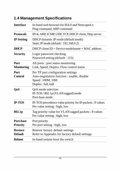
1.4 Management Specifications
Interface In-band web browser for IE4.0 and Netscape4.xPing command, ARP command
Protocols IPv4, ARP, ICMP,UDP, TCP, DHCP client, Http server
IP Setting DHCP dynamic IP mode (default mode)Static IP mode (default : 192.168.0.2)
DHCP DHCP client ID = Device modelname + MAC address
Security Login password checkingPassword setting (default : 123)
Port All ports : port status monitoringMonitoring Link, Speed, Duplex, Flow control status
Port Per TP port configuration settingsControl Auto-negotiation function : enable, disable
Speed : 100M, 10MDuplex : full, half
QoS QoS mode selectionIP-TOS / 802.1p (VLAN tagged) modePort-base mode
IP-TOS IP-TOS precedence value priority for IP packets : 8 valuesPer value setting : high, low
802.1p Tag priority value for VLAN tagged packets : 8 valuesPer value setting : high, low
Port-base Port priorityPriority Per port setting : high, low
Restore Restore factory default settingsDefault Refer to Appendix for factory default settings
Reboot In-band remote boot the switch

-10-
2. Installing the Switches
2.1 UnpackingCheck to see that you have everything before you start the installation.• Installation guide
• The switch unit
• Rubber magnet stand
• One AC power adapter for the unit
2.2 Supply the PowerChecking AC PowerBefore you begin the installation, check the AC voltage of your area. TheAC power adapter which is used to supply the DC power for the unit shouldhave the AC voltage matching the commercial power voltage in your area.The specifications of the AC power adapter are:
• AC input power: AC power voltage of your area• DC output power: Rating +7.5V VDC min. 1.0A
• DC plug type:
DC IN JackThe DC power jack for the AC power adapter is located on the rear of theswitch. Refer to section 1.2 drawing.
Installing the Switch1. Install the switch with the AC power adapter provided.

-11-
2. Connect the power adapter cable to the switch before connectingthe adapter to the AC outlet.
2.3 Port ConfigurationThe switches provide port configuration function through the manage-ment interface. The setting options are shown as follows:
Port Type TP PORTS FX PORTAuto-negotiation Enable/Disable Not allowedSpeed options 100M / 10M Not allowed (fixed 100M)Duplex options Full / Half Not allowed (fixed Full)
When auto-negotiation is enabled, the speed and duplex settings be-come the port highest ability used for auto-negotiation process. Thefinal configurations used with the connected device may be differentfrom the settings after negotiation between two devices. As auto-nego-tiation is disabled, the speed and duplex settings are the forced operatingconfiguration for the connection.
The real time port status for each port connection can be monitoredthrough the management interface. The status are:
Link Physical link statusSpeed Connection speed usedDuplex Duplex mode usedFlow Control Flow control status after negotiation
-12-
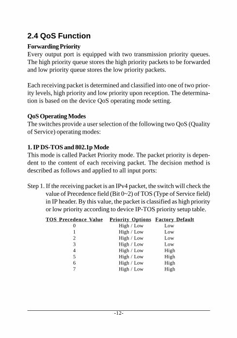
2.4 QoS FunctionForwarding PriorityEvery output port is equipped with two transmission priority queues.The high priority queue stores the high priority packets to be forwardedand low priority queue stores the low priority packets.
Each receiving packet is determined and classified into one of two prior-ity levels, high priority and low priority upon reception. The determina-tion is based on the device QoS operating mode setting.
QoS Operating ModesThe switches provide a user selection of the following two QoS (Qualityof Service) operating modes:
1. IP DS-TOS and 802.1p ModeThis mode is called Packet Priority mode. The packet priority is depen-dent to the content of each receiving packet. The decision method isdescribed as follows and applied to all input ports:
Step 1. If the receiving packet is an IPv4 packet, the switch will check thevalue of Precedence field (Bit 0~2) of TOS (Type of Service field)in IP header. By this value, the packet is classified as high priorityor low priority according to device IP-TOS priority setup table.
TOS Precedence Value Priority Options Factory Default0 High / Low Low1 High / Low Low2 High / Low Low3 High / Low Low4 High / Low High5 High / Low High6 High / Low High7 High / Low High

-13-
Step2. If the receiving packet is not an IP, but an 802.1Q VLAN taggedpacket, the device will check the 3-bit User Priority value in TCI(Tag Control Information) field of packet tag data. By this value,the packet is classified as high priority or low priority accordingto device 802.1p priority setup table.
Tag Priority Value Priority Options Factory Default0 High / Low Low1 High / Low Low2 High / Low Low3 High / Low Low4 High / Low High5 High / Low High6 High / Low High7 High / Low High
Step 3. If the receiving packet is an non-IP and untagged packet, thedevice will classify the packet based on Port-base mode. Refer toPort-base QoS mode for more information.
Note:Under IP DS-TOS/802.1p mode, all incoming tagged packets will be un-tagged on output ports.
2. Port-Base ModeThis mode called port priority mode. The priority level of a receivingpacket is determined by the configured priority of the input port wherethe packet is received and the content of the packet is ignored. Each portmust be pre-configured with a priority level as follows:
Port Number Priority Options Factory DefaultP 1 High / Low LowP 2 High / Low LowP 3 High / Low LowP 4 High / Low LowP 5 High / Low LowP 6 High / Low LowFX High / Low Low

-14-
QoS ManagementRefer to Chapter 3 for more details about the following management objects:
1. QoS Operating mode setting2. IP DS-TOS priority table setup3. 802.1p tag priority table setup4. Port-base priority setup
2.5 DHCP and IP ConfigurationEach switch must be designated an IP address before it can be managedfrom web browser. Basically, the switches provide two methods for IPconfiguration:
1. DHCP modeThe switch requests a dynamic IP address from the first discoveredDHCP server in the network when boot up. In general, the assignedIP can be monitored in the client list on the DHCP server. The modelname and MAC address of the switch is referred as the DHCP clientID. If no DHCP server is discovered after a retry period for about 40seconds, the pre-configured static IP is used automatically.
2. Static IP modeOne pre-configured IP address is used when DHCP mode is disabledor when DHCP mode is enabled and no DHCP server is available.The static IP can be configured through management interface. Eachswitch comes with one identical factory default IP upon devicereception.
It is important to record the MAC address and location where it is in-stalled for each switch. It would help in tracing the IP and device map-ping.

-15-
2.6 Push Button IP SWOne push button IP SW located on rear panel is used to disable DHCP modeand restore static IP back to factory default value. It is useful when you donot recall your static IP setting and DHCP solution is not available.
To make the function work, push the SW and keep for at least 5 secondswhen the switch is powered on to be boot up.
2.7 Making UTP ConnectionsTP Port ConfigurationUse management function to set the required TP port configuration. It isrecommended to set the highest ability for the TP ports as follows:
Auto-negotiation = enabledSpeed = 100MDuplex = Full
This is appropriate to support connection to almost every Ethernet de-vices including those which are not auto-negotiation capable.
CablesDepending on the connection speed, use the appropriate UTP cables forthe connections as follows:
Speed Cables used Distance100M Cat. 5, 5e, or higher grade 100 meters10M Cat. 3, 4, 5, 5e, or higher grade 100 meters
Auto-MDI-X FunctionAn Auto-MDI-X function will automatically detect if a crossover is re-quired and make the swap of Tx pair and Rx pair internally. With thisfunction, straight-through cable can be used for any connection. MDI toMDI-X connection rule is not necessary anymore. In the switches, all TPports are equipped with this function. You can use just straight-throughtype of cables for all your connections.
-16-
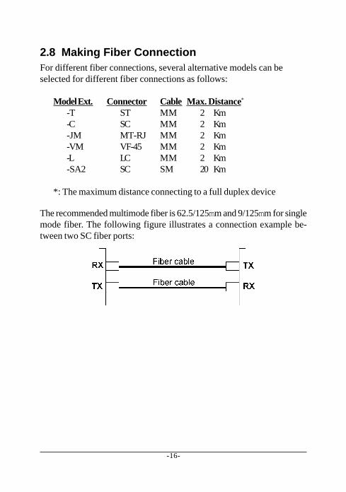
2.8 Making Fiber ConnectionFor different fiber connections, several alternative models can beselected for different fiber connections as follows:
Model Ext. Connector Cable Max. Distance*
-T ST MM 2 Km-C SC MM 2 Km-JM MT-RJ MM 2 Km-VM VF-45 MM 2 Km-L LC MM 2 Km-SA2 SC SM 20 Km
*: The maximum distance connecting to a full duplex device
The recommended multimode fiber is 62.5/125mm and 9/125mm for singlemode fiber. The following figure illustrates a connection example be-tween two SC fiber ports:

-17-
2.9 LED IndicationsFunctionsPOWER : indicates the status of the power supplied to the switch.100/10 : indicates the connection speed between the TP port
and the associated connected device.LINK/Act. : indicates the port link and activity statusFDX/Col. : indicates the duplex mode and collision occurrences
The following table lists the LED states and the indications:
LED State IndicationPOWER OFF No power is supplied to the device.POWER ON Power is supplied to the device.100/10 OFF 10Mbps is used.100/10 ON 100Mbps is used.LINK/Act. OFF No active cable linkLINK/Act. ON An active link is established.LINK/Act. Blink Tx/Rx activitiesFDX/Col ON Full duplex is used.FDX/Col OFF Half duplex is used.FDX/Col Blink Half duplex and collision occurrences

-18-
3. Web Management
3.1 Web BrowserThe system features an http server which can serve the managementrequests coming from any web browser software over internet or intranetnetwork.
Web BrowserCompatible web browser software with JAVA supportMicrosoft Internet Explorer 4.0 or laterNetscape Communicator 4.x or later
Start connectionBefore the switch can be managed from a web browser software, theswitch IP address is required. Consult your LAN administrator if it is notavailable. Start your browser software and enter the IP address of theswitch to which you want to connect. The IP address is used as URL forthe browser software to search the device.
URL : http://xxx.xxx.xxx.xxx/
Factory default IP address : 192.168.0.2
When browser software connects to the switch unit successfully, a Lo-gin screen is provided for you to login to the device as follows:

-19-
Enter your password and click [OK] to login into the switch. The switchcomes with factory default password : 123.
-20-
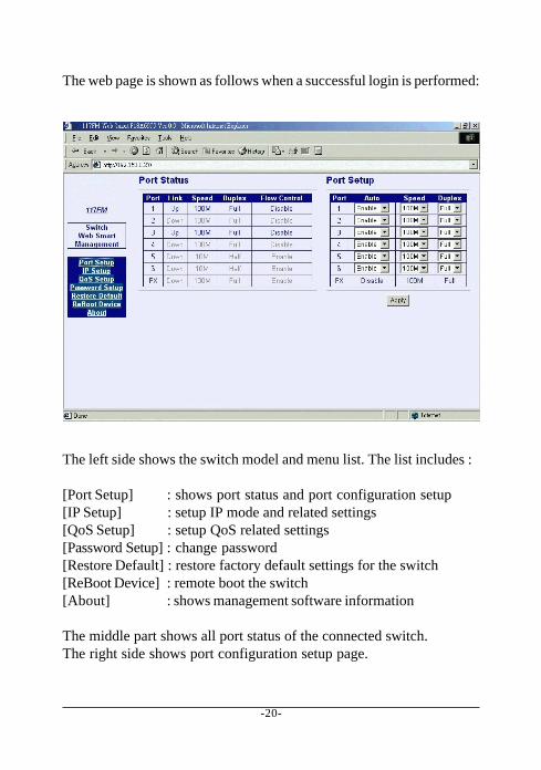
The web page is shown as follows when a successful login is performed:
The left side shows the switch model and menu list. The list includes :
[Port Setup] : shows port status and port configuration setup[IP Setup] : setup IP mode and related settings[QoS Setup] : setup QoS related settings[Password Setup] : change password[Restore Default] : restore factory default settings for the switch[ReBoot Device] : remote boot the switch[About] : shows management software information
The middle part shows all port status of the connected switch.The right side shows port configuration setup page.

-21-
3.2 Port SetupPort StatusPort Status page displays the current port status. The status are:
Port Port number (FX : FX port)Link Port link status, Up = link up, Down = link downSpeed Port speed, 100M = 100Mbps, 10M = 10MbpsDuplex Duplex mode used, Full = full-duplex, Half = half-duplexFlow Control Flow control status, enabled, disabled
Note: The switch is featured with flow control enabled for all ports.However, the flow control may be disabled after auto negotiationwith the connected device, if the connected device does nothave flow control ability.
Port SetupThis page is used to set the port configuration for each port. As auto-negotiation function is enabled, speed and duplex settings specify thehighest port ability for negotiation process between the switch and theauto-negotiation capable link partner. When auto-negotiation functionis disabled, speed and duplex settings specify the forced port configura-tion for the connection. Setup options are:
Auto-negotiation Enabled, disabledSpeed 100M = 100Mbps, 10M = 10MbpsDuplex Full = full-duplex, Half = half-duplex
It is recommended to set auto-negotiation enabled in most of cases andset it disabled only when connecting to an auto-negotiation incapablefull-duplex device.
[Apply] Click to make the setup effective immediately

-22-
3.3 IP Setup
This page includes the following functions:
IP Status Display information of current IP usedIf the current IP address is labeled (DHCP), it means theIP is assigned by DHCP server.
IP Setup Set static IP address to be used when DHCP is disabledor when no DHCP server is available.
DHCP Setup Enable to get and use dynamic IP address assigned byDHCP server. Disable to use Static IP setting.
Any change or click [Apply] do not affect current management connec-tion. They will be effective for next bootup.

-23-
3.4 QoS Setup
QoS SetupThis page sets QoS mode to be used. The functions are as follows:
Mode selected Packet priority decision stepsIP DS-TOS / 802.1p 1. Check Precedence value for IP packets
2. Check priority value of VLAN tagged packets3. Use Port Base priority for non IP and untagged packets
Port Base Priority Ignore packet content and use port priorityas packet priority
Click [Apply] to make change effective immediately.

-24-
3.4.1 IP DS-TOS SetupThis page pre-configures <Precedence value vs. Priority> mapping tablefor priority decision making used for IP packets. Each IP packet carriesone precedence value embedded in its IP header. The packet priority isdetermined based on the mapping table upon it is received. Refer tosection 2.4 for more information.
3.4.2 802.1p Setup
This page pre-configures <Tag priority value vs. Priority> mapping tablefor priority decision making used for VLAN tagged packets. Each taggedpacket carries one priority value embedded in its tag data. The packetpriority is determined based on the mapping table upon it is received.Refer to section 2.4 for more information.

-25-
3.5 Password Setup
Password is used for checking authority for accessing the switch. Tochange password setting, enter your new password and reconfirm theinput again.
Click [Apply] to apply the new password immediately.

-26-
3.6 Restore Default
This command is used to restore all settings back to factory defaultvalues. Click [Restote] to apply immediately. Refer to Appendix for fac-tory default values.

-27-
3.7 ReBoot Device
The command is used to reboot the switch remotely over the network.Normally, it is used after IP settings are changed.
3.8 AboutAbout shows switch model name and software version.
-28-
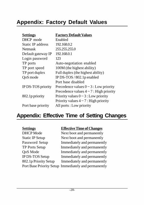
Appendix: Factory Default Values
Settings Factory Default ValuesDHCP mode EnabledStatic IP address 192.168.0.2Netmask 255.255.255.0Default gateway IP 192.168.0.1Login password 123TP ports Auto-negotiation enabledTP port speed 100M (the highest ability)TP port duplex Full duplex (the highest ability)QoS mode IP DS-TOS / 802.1p enabled
Port base disabledIP DS-TOS priority Precedence values 0 ~ 3 : Low priority
Precedence values 4 ~ 7 : High priority802.1p priority Priority values 0 ~ 3 : Low priority
Priority values 4 ~ 7 : High priorityPort base priority All ports : Low priority
Appendix: Effective Time of Setting Changes
Settings Effective Time of ChangesDHCP Mode Next boot and permanentlyStatic IP Setup Next boot and permanentlyPassword Setup Immediately and permanentlyTP Ports Setup Immediately and permanentlyQoS Mode Immediately and permanentlyIP DS-TOS Setup Immediately and permanently802.1p Priority Setup Immediately and permanentlyPort Base Priority Setup Immediately and permanently