Installation manual - SMA RS485 MODULE · SMA RS485 MODULE MD.485-40 (PC-485.BG1) ENGLISH...
22
Installation manual SMA RS485 MODULE MD.485-40 (PC-485.BG1) MD485-40-IA-en-10 | Version 1.0 ENGLISH
Transcript of Installation manual - SMA RS485 MODULE · SMA RS485 MODULE MD.485-40 (PC-485.BG1) ENGLISH...

Installation manualSMA RS485 MODULEMD.485-40 (PC-485.BG1)
MD485-40-IA-en-10 | Version 1.0ENGLISH

Legal ProvisionsThe information contained in these documents is property of SMA Solar Technology AG. Anypublication, whether in whole or in part, requires prior written approval by SMA Solar TechnologyAG. Internal reproduction used solely for the purpose of product evaluation or other proper use isallowed and does not require prior approval.
SMA WarrantyYou can download the current warranty conditions from the Internet at www.SMA-Solar.com.
TrademarksAll trademarks are recognized, even if not explicitly identified as such. Missing designations do notmean that a product or brand is not a registered trademark.Modbus® is a registered trademark of Schneider Electric and is licensed by theModbus Organization, Inc.QR Code is a registered trademark of DENSO WAVE INCORPORATED.Phillips® and Pozidriv® are registered trademarks of Phillips Screw Company.Torx® is a registered trademark of Acument Global Technologies, Inc.
SMA Solar Technology AGSonnenallee 134266 NiestetalGermanyTel. +49 561 9522-0Fax +49 561 9522-100www.SMA.deEmail: [email protected]
Status: 9/18/2017Copyright © 2017 SMA Solar Technology AG. All rights reserved.
Legal Provisions SMA Solar Technology AG
Installation manualMD485-40-IA-en-102
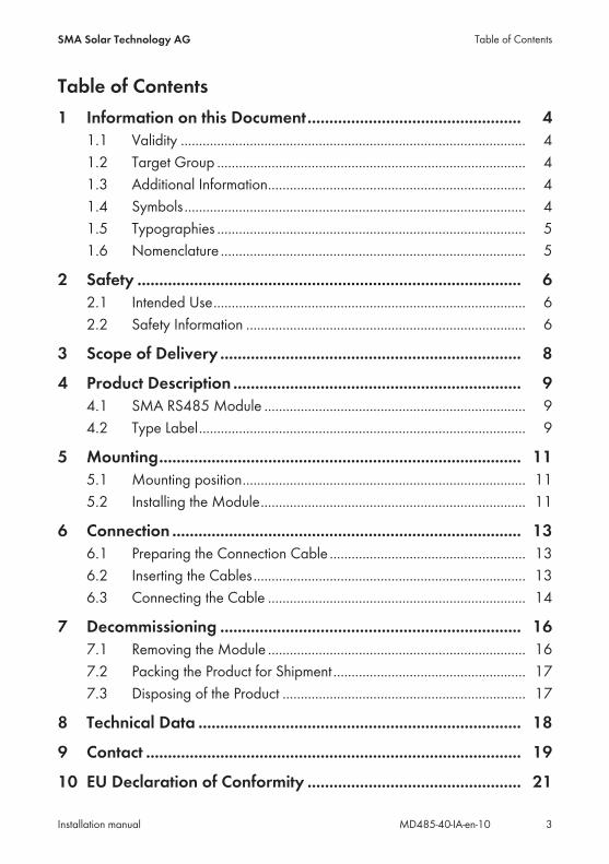
Table of Contents1 Information on this Document................................................. 4
1.1 Validity ............................................................................................... 41.2 Target Group ..................................................................................... 41.3 Additional Information....................................................................... 41.4 Symbols.............................................................................................. 41.5 Typographies ..................................................................................... 51.6 Nomenclature .................................................................................... 5
2 Safety ........................................................................................ 62.1 Intended Use...................................................................................... 62.2 Safety Information ............................................................................. 6
3 Scope of Delivery ..................................................................... 8
4 Product Description .................................................................. 94.1 SMA RS485 Module ........................................................................ 94.2 Type Label.......................................................................................... 9
5 Mounting................................................................................... 115.1 Mounting position.............................................................................. 115.2 Installing the Module......................................................................... 11
6 Connection ................................................................................ 136.1 Preparing the Connection Cable ...................................................... 136.2 Inserting the Cables........................................................................... 136.3 Connecting the Cable ....................................................................... 14
7 Decommissioning ..................................................................... 167.1 Removing the Module ....................................................................... 167.2 Packing the Product for Shipment ..................................................... 177.3 Disposing of the Product ................................................................... 17
8 Technical Data .......................................................................... 18
9 Contact ...................................................................................... 19
10 EU Declaration of Conformity ................................................. 21
Table of ContentsSMA Solar Technology AG
Installation manual 3MD485-40-IA-en-10

1 Information on this Document
1.1 ValidityThis document is valid for the SMA RS485 Module (MD.485-40) with assembly designation"PC-485.BG1" from hardware version A1.
1.2 Target GroupThe tasks described in this document must only be performed by qualified persons. Qualifiedpersons must have the following skills:
• Knowledge of how an inverter works and is operated• Training in how to deal with the dangers and risks associated with installing and using
electrical devices and installations• Training in the installation and commissioning of electrical devices and installations• Knowledge of the applicable standards and directives• Knowledge of and compliance with this document and all safety information
1.3 Additional InformationLinks to additional information can be found at www.SMA-Solar.com:
Document title Document type"RS485 Cabling Plan" Installation manual
1.4 SymbolsSymbol Explanation
Indicates a hazardous situation which, if notavoided, will result in death or serious injury
Indicates a hazardous situation which, if notavoided, can result in death or serious injury
Indicates a hazardous situation which, if notavoided, can result in minor or moderate injury
Indicates a situation which, if not avoided, canresult in property damage
Information that is important for a specific topicor goal, but is not safety-relevant
Indicates a requirement for meeting a specificgoal
Desired result
A problem that might occur
1 Information on this Document SMA Solar Technology AG
Installation manualMD485-40-IA-en-104

1.5 TypographiesTypography Use Examplebold • Display texts
• Elements on a user interface• Terminals• Elements to be selected• Elements to be entered
• The value can be found inthe field Energy.
• Select Settings.• Enter 10 in the field
Minutes.
> • Connects several elements to beselected
• Select Settings > Date.
[Button][Key]
• Button or key to be selected orpressed
• Select [Next].
1.6 NomenclatureComplete designation Designation in this documentPV system PV system
1 Information on this DocumentSMA Solar Technology AG
Installation manual 5MD485-40-IA-en-10

2 Safety
2.1 Intended UseThe SMA RS485 Module enables SMA inverters to establish wired RS485 communication.The RS485 Module must only be installed in the following SMA inverters:
• STP 50-40 (Sunny Tripower CORE1)The inverter still complies with the standard after the product has been installed.The product must only be used in countries for which it is approved or released by SMA SolarTechnology AG and the grid operator.All components must remain within their permitted operating ranges and their installationrequirements at all times.Use this product only in accordance with the information provided in the enclosed documentationand with the locally applicable standards and directives. Any other application may causepersonal injury or property damage.Alterations to the product, e.g. changes or modifications, are only permitted with the express writtenpermission of SMA Solar Technology AG. Unauthorized alterations will void guarantee andwarranty claims and in most cases terminate the operating license. SMA Solar Technology AGshall not be held liable for any damage caused by such changes.Any use of the product other than that described in the Intended Use section does not qualify as theintended use.The enclosed documentation is an integral part of this product. Keep the documentation in aconvenient place for future reference and observe all instructions contained therein.The type label must remain permanently attached to the product.
2.2 Safety InformationThis section contains safety information that must be observed at all times when working on or withthe product.To prevent personal injury and property damage and to ensure long-term operation of the product,read this section carefully and observe all safety information at all times.
Danger to life due to high voltages of the PV arrayWhen exposed to light, the PV array generates dangerous DC voltage, which is present in the DCconductors and the live components of the inverter. Touching the DC conductors or the livecomponents can lead to lethal electric shocks.
• Prior to performing any work on the inverter, always disconnect the inverter from voltagesources on the AC and DC sides as described in the inverter manual. When doing so, notethat even if the DC load-break is switched off, there will be dangerous direct voltage presentin the DC conductors of the inverter.
2 Safety SMA Solar Technology AG
Installation manualMD485-40-IA-en-106

Damage to seals on the enclosure lids in subfreezing conditionsIf you open the enclosure lids when temperatures are below freezing, the enclosure seals can bedamaged. This can lead to moisture entering the inverter.
• Only open the enclosure lids if the ambient temperature is not below -5°C• If a layer of ice has formed on the seal of the lid when temperatures are below freezing,
remove it prior to opening the enclosure lids (e.g. by melting the ice with warm air). Observethe applicable safety regulations.
Damage to the inverter or product due to electrostatic dischargeTouching electronic components can cause damage to or destroy the inverter or the productthrough electrostatic discharge.
• Ground yourself before touching any component.
2 SafetySMA Solar Technology AG
Installation manual 7MD485-40-IA-en-10

3 Scope of DeliveryCheck the scope of delivery for completeness and any externally visible damage. Contact yourdistributor if the scope of delivery is incomplete or damaged.
BA C D
FE
Figure 1: Components included in the scope of delivery
Position Quantity DesignationA 1 Module
B 1 Fastening screw (M5, TX 25)
C 2 4-pole terminal block
D 1 Terminator
E 2 Copper foil
F 1 Quick Reference Guide
3 Scope of Delivery SMA Solar Technology AG
Installation manualMD485-40-IA-en-108

4 Product Description
4.1 SMA RS485 ModuleThe SMA RS485 Module enables SMA inverters to establish wired RS485 communication.
Design of the Module
FA
D D
C
B
BE
Figure 2: Design of the module
Position ExplanationA Opening for the fastening screw
B Openings for the guide pins of the communication assembly
C Jacks for connecting the 4-pole terminal blocks
D Shield clamps
E Type label
F Connector strip on the back of the module for connection to thecommunication assembly in the inverter
4.2 Type LabelThe type label clearly identifies the product. The type label is located on the front of the product.
PC-485.BG1
XXXXX
XX
A
B
C
Figure 3: Design of the type label
Position ExplanationA Device type
B Serial number
C Hardware version
4 Product DescriptionSMA Solar Technology AG
Installation manual 9MD485-40-IA-en-10

You will require the information on the type label to use the product safely and when seekingcustomer support from Service (see Section 9 "Contact", page 19).
4 Product Description SMA Solar Technology AG
Installation manualMD485-40-IA-en-1010

5 Mounting
5.1 Mounting position
DISPLAY
BAT
Max. 30V DC
USB
FCC ID: SVF-KPIC: 9440A-KP20
MFRA
B
X1
X2
A
B
C
Figure 4: Communication assembly in the inverter with mounting position for the module
Position DesignationA Communication assembly
B Module slot M1*
C Module slot M2* Production resources SMA Solar Technology AG recommends using module slot M1 for the module.
5.2 Installing the ModuleMaximum number of modules per inverterYou can only use a maximum of one module of the same device type per inverter.
Procedure:1.
Danger to life due to high voltages of the PV arrayWhen exposed to sunlight, the PV array generates dangerous DC voltage, which is present inthe DC conductors and the live components of the inverter. Touching the DC conductors or thelive components can lead to lethal electric shocks.
• Prior to performing any work on the inverter, always disconnect the inverter from voltagesources on the AC and DC sides as described in the inverter manual. When doing so,note that even if the DC load-break is switched off, there will be dangerous direct voltagepresent in the DC conductors of the inverter.
2. Remove the enclosure lid of the DC Connection Unit. Unscrew all screws with a Torxscrewdriver (TX 25) and remove the enclosure lid carefully forward.
3. Set the screws and the enclosure lid aside and store safely.
5 MountingSMA Solar Technology AG
Installation manual 11MD485-40-IA-en-10

4. Install the module at the desired mounting location. Perform the following steps:• Guide the three guide pins on the
communication assembly through the holesin the module. The holes in which the guidepins must be inserted depend on themounting location.
• Carefully push the module down on theupper edge and on the connection socketsuntil it audibly snaps into both side lockingtabs of the communication assembly. Theconnector strip on the back of the module isautomatically pushed into the socketterminal strip of the communicationassembly.
CLICKCLICK
5. Screw tight the fastening screw with a Torxscrewdriver (TX 25) on the module (torque:1.5 Nm). This additionally fixes the module inplace and grounds it in the inverter enclosure.
5 Mounting SMA Solar Technology AG
Installation manualMD485-40-IA-en-1012
6 Connection
6.1 Preparing the Connection CableDepending on whether the module is located at the end or in the middle of the communication bus,prepare one or two connection cables as described in the following.
Requirements:☐ The cable requirements must be complied with (see Installation Instructions "RS485 Cabling
Plan" at www.SMA-Solar.com).☐ Diameter of the cable when using the cable support sleeve with one hole: at maximum
17 mm☐ Diameter of the cable when using the cable support sleeve with two holes: at maximum
6.5 mm
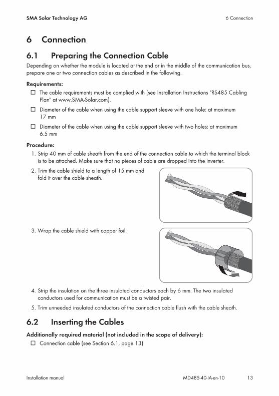
Procedure:1. Strip 40 mm of cable sheath from the end of the connection cable to which the terminal block
is to be attached. Make sure that no pieces of cable are dropped into the inverter.2. Trim the cable shield to a length of 15 mm and
fold it over the cable sheath.
3. Wrap the cable shield with copper foil.
4. Strip the insulation on the three insulated conductors each by 6 mm. The two insulatedconductors used for communication must be a twisted pair.
5. Trim unneeded insulated conductors of the connection cable flush with the cable sheath.
6.2 Inserting the CablesAdditionally required material (not included in the scope of delivery):
☐ Connection cable (see Section 6.1, page 13)
6 ConnectionSMA Solar Technology AG
Installation manual 13MD485-40-IA-en-10
Procedure:1. Make sure that the inverter has been disconnected and is secured against reconnection (see
the inverter manual).2. Remove the swivel nut from the cable gland for the communication cable.3. Thread the swivel nut over the cable.4. Press the two-hole cable support sleeve out of the cable gland.5. Remove the sealing plug from one of the enclosure openings of the two-hole cable support
sleeve and insert the cable into the enclosure opening.6. Press the two-hole cable support sleeve with the cable into the cable gland and guide the
cable to the communication assembly in the DC Connection Unit. Ensure that any unusedenclosure openings of the two-hole cable support sleeve are sealed with sealing plugs.
7. Tighten the swivel nut on the cable gland hand-tight. This will secure the cable.
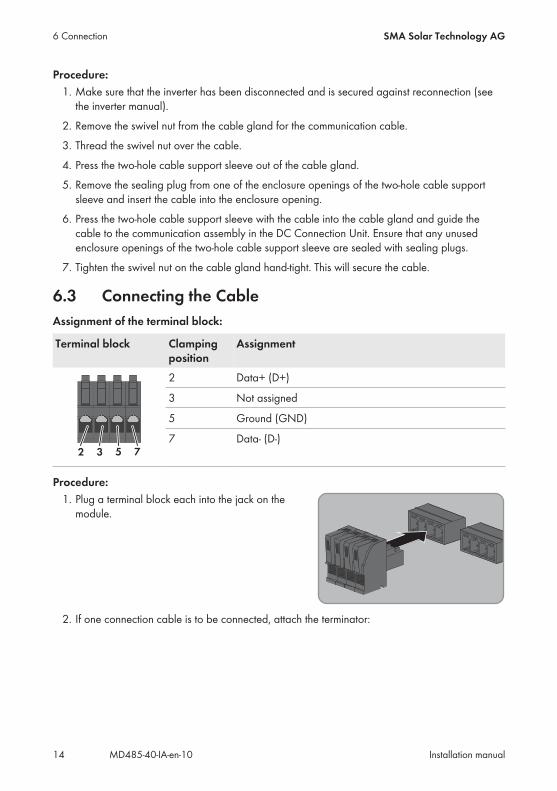
6.3 Connecting the CableAssignment of the terminal block:
Terminal block Clampingposition
Assignment
2 3 5 7
2 Data+ (D+)
3 Not assigned
5 Ground (GND)
7 Data- (D-)
Procedure:1. Plug a terminal block each into the jack on the
module.
2. If one connection cable is to be connected, attach the terminator:
6 Connection SMA Solar Technology AG
Installation manualMD485-40-IA-en-1014
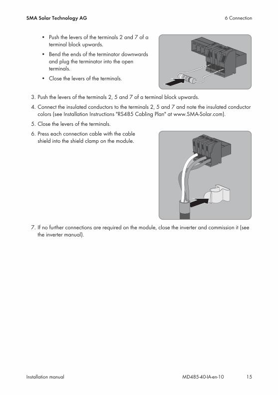
• Push the levers of the terminals 2 and 7 of aterminal block upwards.
• Bend the ends of the terminator downwardsand plug the terminator into the openterminals.
• Close the levers of the terminals.
3. Push the levers of the terminals 2, 5 and 7 of a terminal block upwards.4. Connect the insulated conductors to the terminals 2, 5 and 7 and note the insulated conductor
colors (see Installation Instructions "RS485 Cabling Plan" at www.SMA-Solar.com).5. Close the levers of the terminals.6. Press each connection cable with the cable
shield into the shield clamp on the module.
7. If no further connections are required on the module, close the inverter and commission it (seethe inverter manual).
6 ConnectionSMA Solar Technology AG
Installation manual 15MD485-40-IA-en-10

7 Decommissioning
7.1 Removing the ModuleProcedure:
1.
Danger to life due to high voltages of the PV arrayWhen exposed to sunlight, the PV array generates dangerous DC voltage, which is present inthe DC conductors and the live components of the inverter. Touching the DC conductors or thelive components can lead to lethal electric shocks.
• Prior to performing any work on the inverter, always disconnect the inverter from voltagesources on the AC and DC sides as described in the inverter manual. When doing so,note that even if the DC load-break is switched off, there will be dangerous direct voltagepresent in the DC conductors of the inverter.
2. Remove the enclosure lid of the DC Connection Unit. Unscrew all screws with a Torxscrewdriver (TX 25) and remove the enclosure lid carefully forward.
3. Set the screws and the enclosure lid aside and store safely.4. Remove all connecting terminal plates from the used connection sockets of the module.5. Unscrew the fastening screw on the module
using a Torx screwdriver (TX 25).
6. Remove the module:• Press the right or left locking tab of the
communication assembly slightly outwardsand pull the module slightly forwardsholding the lower end until the module isreleased from the interlock of the lockingtab.
1
2
• Grab the module by the upper and lower edge with one hand.
7 Decommissioning SMA Solar Technology AG
Installation manualMD485-40-IA-en-1016
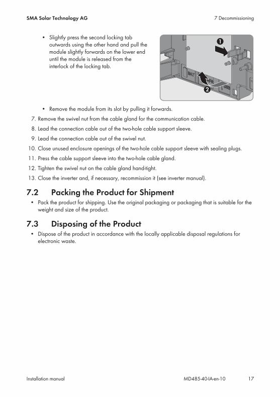
• Slightly press the second locking taboutwards using the other hand and pull themodule slightly forwards on the lower enduntil the module is released from theinterlock of the locking tab.
1
2
• Remove the module from its slot by pulling it forwards.7. Remove the swivel nut from the cable gland for the communication cable.8. Lead the connection cable out of the two-hole cable support sleeve.9. Lead the connection cable out of the swivel nut.
10. Close unused enclosure openings of the two-hole cable support sleeve with sealing plugs.11. Press the cable support sleeve into the two-hole cable gland.12. Tighten the swivel nut on the cable gland hand-tight.13. Close the inverter and, if necessary, recommission it (see inverter manual).
7.2 Packing the Product for Shipment• Pack the product for shipping. Use the original packaging or packaging that is suitable for the
weight and size of the product.
7.3 Disposing of the Product• Dispose of the product in accordance with the locally applicable disposal regulations for
electronic waste.
7 DecommissioningSMA Solar Technology AG
Installation manual 17MD485-40-IA-en-10

8 Technical DataGeneral Data
Mounting location In the inverter
Voltage supply Via the inverter
Mechanical Data
Width x height x depth 60 mm x 105 mm x 33 mm
Ambient Conditions for Storage/Transport
Ambient temperature -40°C to +70°C
Relative humidity, non-condensing 10% to 100%
Maximum height above mean sea level 3000 m
Communication
Interface RS485
Maximum cable length 1200 m
Terminals
Type of plug 4-pole spring-cage terminal
Number of RS485 connections 2
8 Technical Data SMA Solar Technology AG
Installation manualMD485-40-IA-en-1018

9 ContactIf you have technical problems with our products, please contact the SMA Service Line. We requirethe following information in order to provide you with the necessary assistance:
• Inverters:– Serial number– Firmware version– Special country-specific settings (if applicable)
• Module:– Serial number– Hardware version
• Detailed description of the problem
DeutschlandÖsterreichSchweiz
SMA Solar Technology AGNiestetalSunny Boy, Sunny Mini Central,Sunny Tripower:+49 561 9522‑1499Monitoring Systems(Kommunikationsprodukte):+49 561 9522‑2499Fuel Save Controller(PV-Diesel-Hybridsysteme):+49 561 9522-3199Sunny Island, Sunny Boy Storage, Sunny Backup:+49 561 9522-399Sunny Central,Sunny Central Storage:+49 561 9522-299SMA Online Service Center:www.SMA-Service.com
BelgienBelgiqueBelgiëLuxemburgLuxembourgNederland
SMA Benelux BVBA/SPRLMechelen+32 15 286 730SMA Online Service Center:www.SMA-Service.com
ČeskoMagyarországSlovensko
SMA Service PartnerTERMS a.s.+420 387 6 85 111SMA Online Service Center:www.SMA-Service.com
Türkiye SMA Service PartnerDEKOM Ltd. Şti.+90 24 22430605SMA Online Service Center:www.SMA-Service.com
France SMA France S.A.S.Lyon+33 472 22 97 00SMA Online Service Center :www.SMA-Service.com
ΕλλάδαΚύπρος
SMA Service PartnerAKTOR FM.Αθήνα+30 210 8184550SMA Online Service Center:www.SMA-Service.com
9 ContactSMA Solar Technology AG
Installation manual 19MD485-40-IA-en-10

EspañaPortugal
SMA Ibérica Tecnología Solar,S.L.U.Barcelona+34 935 63 50 99SMA Online Service Center:www.SMA-Service.com
UnitedKingdom
SMA Solar UK Ltd.Milton Keynes+44 1908 304899SMA Online Service Center:www.SMA-Service.com
Italia SMA Italia S.r.l.Milano+39 02 8934-7299SMA Online Service Center:www.SMA-Service.com
BulgariaRomânia
SMA Service PartnerRenovatio Solar+40 372 756 599SMA Online Service Center:www.SMA-Service.com
United ArabEmirates
SMA Middle East LLCAbu Dhabi+971 2234 6177SMA Online Service Center:www.SMA-Service.com
India SMA Solar India Pvt. Ltd.Mumbai+91 22 61713888
SMA Solar (Thailand) Co., Ltd.
+66 2 670 6999
대한민국 SMA Technology Korea Co.,Ltd.서울+82-2-520-2666
South Africa SMA Solar TechnologySouth Africa Pty Ltd.Cape Town08600SUNNY (08600 78669)International:+27 (0)21 826 0600SMA Online Service Center:www.SMA-Service.com
ArgentinaBrasilChilePerú
SMA South America SPASantiago de Chile+562 2820 2101
Australia SMA Australia Pty Ltd.SydneyToll free for Australia:1800 SMA AUS(1800 762 287)International: +61 2 9491 4200
Other countries International SMA Service LineNiestetal00800 SMA SERVICE(+800 762 7378423)SMA Online Service Center:www.SMA-Service.com
9 Contact SMA Solar Technology AG
Installation manualMD485-40-IA-en-1020

10 EU Declaration of Conformitywithin the scope of the EU directives
• Electromagnetic compatibility 2014/30/EU (29.3.2014 L 96/79-106)(EMC)
SMA Solar Technology AG confirms herewith that the products described in this document are incompliance with the fundamental requirements and other relevant provisions of the above-mentioned directives. The entire EU Declaration of Conformity can be found at www.SMA-Solar.com.
10 EU Declaration of ConformitySMA Solar Technology AG
Installation manual 21MD485-40-IA-en-10

www.SMA-Solar.com