Installation Manual - Northern Tool - Quality Tools for ... · Quality since 1946 9049 Tyler Blvd....
12
Quality since 1946 9049 Tyler Blvd. • Mentor, Ohio 44060 Phone (440) 974-8888 • Fax (440) 974-0165 Toll-Free Fax 800-841-8003 • buyersproducts.com Installation Manual Self-Contained Hopper Spreaders Carbon & Stainless Steel Models CAUTION Do not overload vehicle beyond the vehicle’s Gross Vehicle Weight Rating (GVWR) or Gross Axel Weight Ratings (GAWR). Check the vehicle’s load rating certification sticker for maximum vehicle capacity. Table of Contents Warranty Information................................................................. 1 General Information ................................................................... 1 Safety Precautions ...................................................................... 2 Installation Instructions ............................................................ 3 Spreader Operation..................................................................... 4 Spreader Maintenance ............................................................... 6 Repair Parts & Drawings ........................................................... 8 Spreader Models and Specifications Model # Hopper Length Material Chute Length Overall Length Overall Width Overall Height Empty Weight Cap. Struck Cap. Rounded SCH072SS 6' Stainless Standard 91¾" 47" * 32½" 639# 1.35 1.6 SCH072SSX 6' Stainless Extended 91¾" 47" * 32½" 655# 1.35 1.6 SCH096C 8' Carbon Standard 115¾" 47" * 32½" 857# 1.8 2.1 SCH096CX 8' Carbon Extended 115¾" 47" * 32½" 875# 1.8 2.1 SCH096SS 8' Stainless Standard 115¾" 47" * 32½" 745# 1.8 2.1 SCH096SSX 8' Stainless Extended 115¾" 47" * 32½" 758# 1.8 2.1 SCH120SS 10' Stainless Standard 139¾" 47" 32½" 789# 2.3 2.7 SCH120SSX 10' Stainless Extended 139¾" 47" 32½" 804# 2.3 2.7 * 6' spreaders – Serial numbers 1404 and below – Overall Width = 50¾" * 8' spreaders – Serial numbers 5934 and below – Overall Width = 50¾" General Information 1. Recommended Vehicle Requirements: • SCH072 & SCH096 models: 3/4 or 1 ton Pick-up Truck Above 8500# GVWR • SCH120 models: Flat Bed or Dump Trucks Above 15,000# GVWR SPREADER WARRANTY INFORMATION This warranty replaces all previous warranties and no employee of this company is authorized to extend additional warranties, or agreements, or implications not explicitly covered herein. Buyers Products Company warrants all parts of the product to be free from defects in material and workmanship for a period of one (1) year, excluding the gasoline engine, from the date of installa- tion. Parts must be properly installed and used under normal condi- tions. Normal wear is excluded. Any part which has been altered, including modifications, misuse, accident, or lack of maintenance will not be considered under this warranty. The sole responsibility of Buyers Products Company under this warranty is limited to repairing or replacing any part(s) which are returned, prepaid, 30 days after such defect is discovered, and returned part(s) are found to be defective by Buyers Products Company. Authorization from Buyers Products Company must be obtained before returning any part. The following information must accom- pany defective parts returned to Buyers Products Company: RMA#, spreader model, serial number, date installed, and distributor from whom purchased. Buyers Products Company shall not be liable for damage arising out of failure of any unit to operate properly, or failure, or delay in work, or for any consequential damages. No charges for transportation or labor performed on any part will be allowed under this warranty. The gasoline engine is solely warranted through engine’s manu- facturer. All engine related warranty claims are to be processed through the engine’s manufacturer. This information is explained in the engine owner’s manual. Manual applies to: • 72" Spreaders (serial numbers 1200 and above) • 96" Spreaders (serial numbers 4884 and above) • 120" Spreaders (serial numbers 1000 and above)
Transcript of Installation Manual - Northern Tool - Quality Tools for ... · Quality since 1946 9049 Tyler Blvd....

Quality since 19469049 Tyler Blvd. • Mentor, Ohio 44060
Phone (440) 974-8888 • Fax (440) 974-0165Toll-Free Fax 800-841-8003 • buyersproducts.com
Installation ManualSelf-Contained Hopper Spreaders Carbon & Stainless Steel Models
CAUTIONDo not overload vehicle beyond the vehicle’s Gross Vehicle Weight Rating (GVWR) or Gross Axel Weight Ratings (GAWR). Check the vehicle’s load rating certification sticker for maximum vehicle capacity.
Table of Contents
Warranty Information .................................................................1General Information ...................................................................1Safety Precautions ......................................................................2Installation Instructions ............................................................3Spreader Operation .....................................................................4Spreader Maintenance ...............................................................6Repair Parts & Drawings ...........................................................8
Spreader Models and Specifications
Model # Hopper Length Material
Chute Length
Overall Length
Overall Width
Overall Height
Empty Weight
Cap. Struck
Cap. Rounded
SCH072SS 6' Stainless Standard 91¾" 47" * 32½" 639# 1.35 1.6SCH072SSX 6' Stainless Extended 91¾" 47" * 32½" 655# 1.35 1.6SCH096C 8' Carbon Standard 115¾" 47" * 32½" 857# 1.8 2.1SCH096CX 8' Carbon Extended 115¾" 47" * 32½" 875# 1.8 2.1SCH096SS 8' Stainless Standard 115¾" 47" * 32½" 745# 1.8 2.1SCH096SSX 8' Stainless Extended 115¾" 47" * 32½" 758# 1.8 2.1SCH120SS 10' Stainless Standard 139¾" 47" 32½" 789# 2.3 2.7SCH120SSX 10' Stainless Extended 139¾" 47" 32½" 804# 2.3 2.7* 6' spreaders – Serial numbers 1404 and below – Overall Width = 50¾"* 8' spreaders – Serial numbers 5934 and below – Overall Width = 50¾"
General Information
1. Recommended Vehicle Requirements:• SCH072 & SCH096 models: 3/4 or 1 ton Pick-up Truck Above 8500# GVWR• SCH120 models: Flat Bed or Dump Trucks Above 15,000# GVWR
SPREADER WARRANTY INFORMATION This warranty replaces all previous warranties and no employee of this company is authorized to extend additional warranties, or agreements, or implications not explicitly covered herein.
Buyers Products Company warrants all parts of the product to be free from defects in material and workmanship for a period of one (1) year, excluding the gasoline engine, from the date of installa-tion. Parts must be properly installed and used under normal condi-tions. Normal wear is excluded.
Any part which has been altered, including modifications, misuse, accident, or lack of maintenance will not be considered under this warranty.
The sole responsibility of Buyers Products Company under this warranty is limited to repairing or replacing any part(s) which are returned, prepaid, 30 days after such defect is discovered, and returned part(s) are found to be defective by Buyers Products Company.
Authorization from Buyers Products Company must be obtained before returning any part. The following information must accom-pany defective parts returned to Buyers Products Company: RMA#, spreader model, serial number, date installed, and distributor from whom purchased.
Buyers Products Company shall not be liable for damage arising out of failure of any unit to operate properly, or failure, or delay in work, or for any consequential damages. No charges for transportation or labor performed on any part will be allowed under this warranty.
The gasoline engine is solely warranted through engine’s manu-facturer. All engine related warranty claims are to be processed through the engine’s manufacturer. This information is explained in the engine owner’s manual.
Manual applies to: • 72" Spreaders (serial numbers 1200 and above) • 96" Spreaders (serial numbers 4884 and above) • 120" Spreaders (serial numbers 1000 and above)

Quality since 1946
�
2. Average Material Weights:
SAEGRADE2 SAEGRADE5 ft-lbS ft-lbS
1/4-20 6 9 5/16-18 11 18 3/8-18 19 31 3/8-24 24 46 7/16-14 30 50 1/2-13 45 75 9/16-12 66 110 5/8-11 93 150
Note: To calculate the total spreader weight (including ice control material); add the empty spreader weight plus the ice control material and spreader accessories.
4. Recommended Fastener Torques:
Maintain all fastener torques as shown in the following table. Failure to do so may cause injury to persons.
WARNINGVerify that the above oil viscosity meets your oper-ating temperature requirements. If not, empty and refill with the proper viscosity oil. Before starting spreader, check that the engine crankcase and gear-box are filled to the proper level with lubricant.
5. Engine and Gearbox Oil:
The engine crankcase is filled with 1 quart of SAE 5W-30 motor oil at the factory. The gearbox is filled with SAE 90 gear lubricant at the factory.
WARNINGObserve the following Safety Precautions before, during and after operating this spreader. By follow-ing these precautions and common sense, possible injury to persons and potential damage to this machine may be avoided.
Safety Precautions
MAtERIAl WEIGHt(POUNDSPERCUbICYARD)
#1 Rock Salt 950 #2 Rock Salt 1,215 Coarse Sand - Dry 2,565 Coarse Sand - Wet 3,240
HOPPER CAPACITIES
72" HOPPER 96" HOPPER 120" HOPPER
12" .33 CU-YD .50 CU-YD .60 CU-YD
19" .75 CU-YD 1.0 CU-YD 1.25 CU-YD
27" 1.35 CU-YD 1.80 CU-YD 2.30 CU-YD
"12
"19
"27
3. Hopper Storage Capacity
1. Read this entire Owner’s Manual before operating this spreader. This includes the engine Operator’s Manuals.
2. Read all safety decals on the spreader before operating the spreader.
3. Check to make sure all safety guards are securely mount-ed into place before operating this spreader.
4. Make sure the engine cover is securely fastened to the spreader before operating the spreader.
5. Verify that all personnel are clear of the spreader spray area before starting or operating this spreader.
6. Keep all loose clothing, hair, jewelry and limbs clear of the spreader before starting or operating this spreader.
7. Do not over-load your vehicle beyond payload limits. If there are any questions, contact the vehicle manufacturer.
8. Do not adjust, clean, oil or unclog material jams without first turning off the spreader, removing the engine spark plug connector.
9. Do not climb on or in the spreader during operation. Do not ride on the spreader while the vehicle is in motion.
10. Make sure the spreader is securely fastened to the ve-hicle in accordance with this manual.
11. Do not operate a spreader that is in need of maintenance or repairs.
12. Never lay tools or equipment on top of the spreader’s 12V
Quality since 1946
�
DC battery. This could accidentally ground the positive (+) battery terminal, resulting in electrical shock, burns or dam-age to the vehicle or equipment.
13. Avoid contact with battery acid. Battery acid can seri-ously burn eyes or skin. Battery acid can also burn holes in clothing.
14. Always disconnect the battery before removing or replac-ing any electrical components.
15. A charging battery gives off gases that can explode if touched by a spark or flame. Cover the top of the battery with electrically non-conductive material to keep sparks away from battery gases.
16. If the spreader must be operated with the spreader bat-tery disconnected, insulate the positive (red) battery cable and red wire from the engine alternator with electrical tape.
Installation Instructions
1. Mounting the Spreader onto the Vehicle:A. Remove the tailgate from the vehicle.
B. Lift the spreader from the lifting loop or square knock-out in hoppers rear cross member (toward rear of the truck).
The lifting point is placed at the approximate balance point of the spreader. Residual material, gasoline, oil, battery, top screen, or inverted vee assembly may affect this balance point.
C. Elevate the spreader off the vehicle with lumber. Place lumber under the side gussets of the spreader. This will help with removal of excess material that accumulates under the spreader.
D. Center the spreader on the vehicle with the ends of the sill extensions 14" to the rear of the nearest vertical obstruc-tion (bumper, trailer hitch, etc). It is recommended that the Spinner/Chute Assembly be loosely attached to the hopper to avoid any interference between the vehicle and the Spin-ner/Chute Assembly.
E. Bolt the spreader to the vehicle frame through the lengths of lumber using the holes located in each of the four (4) side gussets. Use 1/2" SAE Grade 5 hardware as required by vehicle application.
F. In addition secure the spreader to the vehicle by attach-ing the four (4) tie-down eyes located at each corner of the spreader to the vehicle’s factory installed anchor points us-ing suitable tie-down devices.
• The spreader must be securely fastened to the frame of the vehicle.• Verify with the vehicle’s manufacturer that the factory installed anchor points are designed for tie-down of such load.• Periodically check that the spreader mounting hardware is securely tightened.
2. Mounting the Spinner/Chute AssemblyA. Attach the Spinner/Chute Assembly to the spreader using the four (4) 3/8-16 X 3/4" hex head screws, flat washers, lock washers, and nuts. The flat washers are to be placed over the slots in the sill extensions. Push the chute assembly forward towards the cab of the vehicle. Loosely attach the hardware, but do not tighten at this time.
B. Install the roller chain between the spinner/chute sprock-et and the gearbox sprocket. Make sure both sprockets are in-line with one another. If the sprockets are out of align-ment, adjust the height of the gearbox sprocket to correct alignment. Install the roller chain master link.
C. To adjust the roller chain tension: First pull the spinner/chute assembly away from the rear of the vehicle to take up slack in chain then tighten chute screws. The correct chain tension should allow a 5/16" deflection midway between both chain sprockets. If additional adjustment is needed, loosen the spinner shaft bearing bolts and slide the shaft away from the gearbox sprocket. Be sure to maintain the vertical alignment of the spinner shaft and bearings before tightening the hardware.
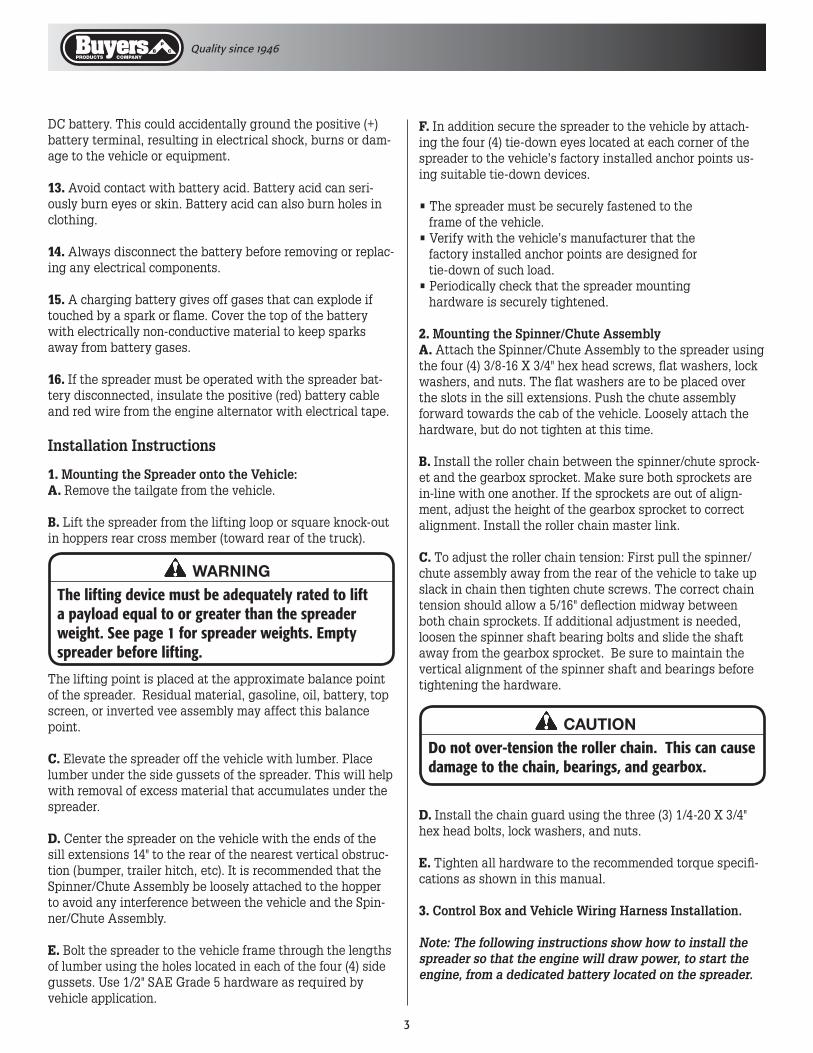
WARNINGThe lifting device must be adequately rated to lift a payload equal to or greater than the spreader weight. See page 1 for spreader weights. Empty spreader before lifting.
CAUTIONDo not over-tension the roller chain. This can cause damage to the chain, bearings, and gearbox.
D. Install the chain guard using the three (3) 1/4-20 X 3/4" hex head bolts, lock washers, and nuts. E. Tighten all hardware to the recommended torque specifi-cations as shown in this manual.
3. Control Box and Vehicle Wiring Harness Installation.
Note: The following instructions show how to install the spreader so that the engine will draw power, to start the engine, from a dedicated battery located on the spreader.
Quality since 1946
�
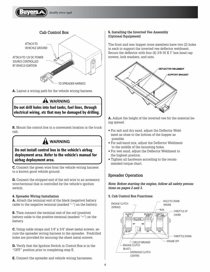
ENGAGE CLUTCH(SPREAD)
DISENGAGE CLUTCH (CENTER)
ENGAGE CLUTCH(BLAST)
HOLD TO CRANK ENGINE
RUN
ENGINE OFF
THROTTLE DOWN
THROTTLE UPCHOKE
CIRCUIT BREAKER
A. Layout a wiring path for the vehicle wiring harness.
5. Installing the Inverted Vee Assembly (Optional Equipment)
The front and rear hopper cross members have two (2) holes in each to support the inverted vee deflector weldment. Secure the deflector with four (4) 3/8-16 X 1" hex head cap screws, lock washers, and nuts.
ATTACH TO VEHICHLE GROUND
ATTACH TO 12V DC POWERSOURCE CONTROLLEDBY VEHICLE IGNITION
TO SPREADER HARNESS
WARNINGDo not drill holes into fuel tanks, fuel lines, through electrical wiring, etc that may be damaged by drilling.
A. Adjust the height of the inverted vee for the material be-ing spread:
• For salt and dry sand, adjust the Deflector Weld- ment as close to the bottom of the hopper as possible.• For salt/sand mix, adjust the Deflector Weldment to the middle of the mounting holes.• For wet sand, adjust the Deflector Weldment to the highest position.• Tighten all hardware according to the recom- mended torque chart.
WARNING
Do not install control box in the vehicle’s airbag deployment area. Refer to the vehicle’s manual for airbag deployment area.
Cab Control Box
B. Mount the control box in a convenient location in the truck cab.
C. Connect the green wire from the vehicle wiring harness to a known good vehicle ground.
D. Connect the stripped end of the red wire to an accessory wire/terminal that is controlled by the vehicle’s ignition switch.
4. Spreader Wiring InstallationA. Attach the terminal end of the black (negative) battery cable to the negative terminal (marked “-”) on the battery.
B. Then connect the terminal end of the red (positive) battery cable to the positive terminal (marked “+”) on the battery.
C. Using cable straps and 1/4" x 3/4" sheet metal screws, se-cure the spreader wiring harness to the spreader. Predrilled holes are provided for securing the sheet metal screws.
D. Verify that the Ignition Switch in Control Box is in the “OFF” position prior to completing step E.
E. Connect the spreader and vehicle wiring harnesses.
Spreader Operation
Note: Before starting the engine, follow all safety precau-tions on pages 2 and 3.
1. Cab Control Box Functions:
Quality since 1946
�
A. The clutch switch is a three position switch with the fol-lowing functions:
“OFF” position: While in this position, with the engine running, the spreader feed chain and the spinner disk will not spin. Therefore, the spreader will not spread ice control material.
“ON” position: While in this position, the spreader feed chain and the spinner disk will spin with the engine run-ning.
“BLAST” position: While in this position, with the engine running, the spreader feed chain and the spinner disk will spin. In this position switch can only be activated when held into the “BLAST” position.
B. The ignition switch is a three position switch with the following functions:
“OFF” position: While in this position, 12V DC power is shut off to the spreader. To turn off the spreader, flip the switch to this position.
“ON” position: While in this position, 12V DC power is turned on to the spreader.
“START” position: While holding in this position, the spreader’s engine starter is activated.
C. The throttle switch is a two position switch with the fol-lowing functions: “CHOKE/FAST” position: While in this position, the engine speed will increase until the engine linkage reaches its choke position.
“IDLE” position: While in this position, the engine speed will decrease.
2. Starting the EngineA. Verify that the clutch switch and ignition switch on the cab control box are in the “OFF” position.
B. Turn the vehicle’s ignition to the “ON” position.
C. Press the spreader’s ignition switch to the “ON” position.
D. Press the throttle switch on the cab control box to the “Idle” position and hold for approximately two seconds.
E. Hold the ignition switch in the “START” position.
F. While the engine is cranking, press and hold the throttle switch to the “CHOKE/FAST” position.
G. Release the ignition and throttle switches when the engine starts.
H. After the engine starts, hold the throttle switch to the “IDLE” position to release the choke (hold switch for 1/2-1 seconds).
3. Stopping the EngineA. Reduce engine RPM by holding throttle switch to the “IDLE” position for 2-3 sec. To stop the engine, press the ignition switch to the “OFF” position.
4. Clutch OperationA. Start the engine and adjust the speed to slightly above idle.B. Push the clutch switch into the “ON” position.
C. Increase the engine RPM by pressing the throttle switch to the “CHOKE/FAST” position.
D. It is recommended that the clutch only be engaged at the lowest possible speed without stopping the engine. This practice will prevent premature spinner chain failure and chain tension loss.
E. Do not repeatedly use the “Blast” function for the clutch. This practice will prevent premature clutch and flex coupler failure and breakage.
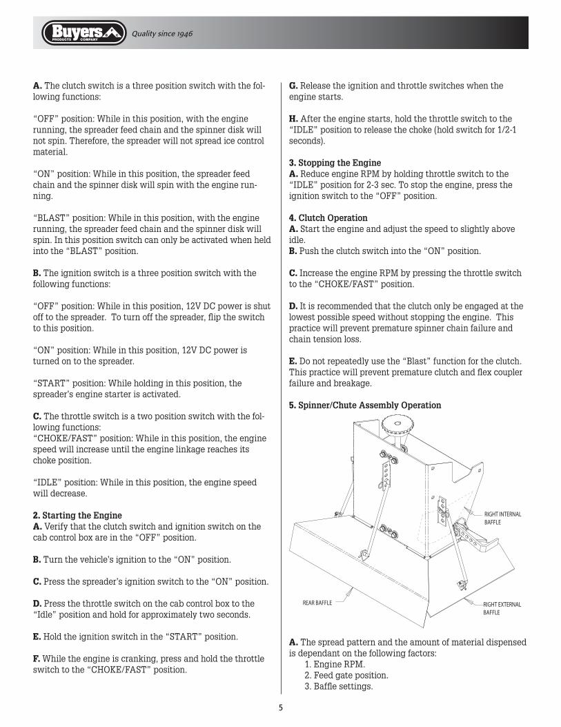
5. Spinner/Chute Assembly Operation
REAR BAFFLE RIGHT EXTERNALBAFFLE
RIGHT INTERNAL BAFFLE
A. The spread pattern and the amount of material dispensed is dependant on the following factors: 1. Engine RPM. 2. Feed gate position. 3. Baffle settings.

Quality since 1946
�
B. Keep the following rules in mind:• Decreasing engine RPM will decrease the amount of material coming to the spinner.• Increasing engine RPM will increase the amount of material coming to the spinner.• Size of the feed gate opening will increase or decrease the amount of material coming to the spinner.
Below are illustrations that show the baffles effect on the spread pattern as viewed from the top of the spinner disk.
6. Precautions
A. If the feed chain does not move because of dense material or a material jam, remove all material from the hopper and free the chain.
B. If the material in the hopper freezes, move the spreader into a warm area to thaw.
C. To prevent the feed chain from freezing, do not store ma-terial in the spreader.
D. The gearbox is designed to only accept torque from the input shaft. Therefore, DO NOT ATTEMPT TO FREE THE FEED CHAIN BY USING A PIPE OR SIMILAR TOOL TO MOVE OR DISLODGE THE CHAIN. If the feed chain is moved, the gears within the gearbox will strip. This action will void all warranties.
Spreader Maintenance
1. Use dielectric grease on all electrical connections before an electrical connection is made or after a connector is dis-connected.
2. Grease the following: • Idler shaft bearings (2) • Drive shaft bearings (2) • Spinner shaft bearings (2) • Flanged bearing located between gearbox and clutch. • Gearbox input shaft (if equipped with fitting)
3. Check gearbox oil level periodically and maintain the oil level by adding appropriate lubricant.
4. Fill the engine crankcase with recommended oil to the full line. Read the engine owner’s manual for the recommended oil viscosity for your operating conditions. Check the oil level periodically and maintain the oil level. Clean and lubricate engine’s choke throttle linkage.
5. Check the Feed Chain tension periodically.A. To check the tension, measure in 21"-25" from the rear edge of the sills. Push up on the chain with your hand. The conveyor chain should lift up 2"-3" off the conveyor chain guide or cross angles.
Both internalbaffles out
Left baffle in,Right baffle out
Right baffle in,Left baffle out
All baffles adjusteddown for a confinedspread pattern
Right baffle deflectsmaterial down;heavy on right side
Left baffle deflectsmaterial down;heavy on left side
Internal Baffle Adjustment
External Baffle Adjustment
CAUTIONAlways follow the following precautions so as not to cause damage to the spreader.
CAUTIONThe engine crankcase and gearbox must be filled and maintained with oil. The engine crankcase oil must be of the correct viscosity for the intended spreader operating conditions. Refer to the engine’s owner manual to determine the correct viscosity. Operating the engine or gearbox without oil (or without a sufficient amount of oil) can cause per-manent damage to the engine or crankcase.
E. Check and maintain the correct oil level for both the engine crankcase and the gearbox. The engine crankcase is filled with 1 quart of SAE 5W-30 motor oil at the factory. The gearbox is filled with SAE 90 gear lubricant at the factory.
FeedChain
Rear of SillExtension
2" - 3"
21" - 25"

Quality since 1946
�
6. Maintain the correct tension on the following roller chains:A. Engine to Gearbox Input Sprocket.B. Spinner Shaft to Gearbox Input Sprocket.
The correct chain tension allows 5/16" deflection midway between respective sprockets. Oil both roller chains often, and at the end of each season.
To loosen or tighten Chain A: loosen the four (4) 3/8-16 X 1 carriage bolts that fasten the engine mount stand to the engine deck and slide the engine mount stand.
To loosen or tighten Chain B: First, loosen the spinner chute fasteners and slide the spinner/chute assembly. If additional adjustment is needed, loosen the spinner shaft bearing bolts and slide the spinner shaft. Be sure to maintain the vertical alignment of the spinner shaft and bearings before tighten-ing the hardware.
7. Empty the spreader of all ice control material when not in use to prevent a frozen feed chain.
8. Wash out the spreader when it is not in use. At the end of the season wash out the spreader to remove all ice control materials. Thoroughly dry all metal surfaces. Paint and oil all bare metal surfaces and chains to protect from rust. Properly store the spreader for the next season.
9. To minimize problems and extend the life of the electric clutch, the following procedures are recommended:A. At the end of the season, remove and clean the clutch.
B. After cleaning, coat both mating surfaces of the clutch with oil or light grease.
C. Remove oil and grease prior to using the clutch again.
10. Engine RepairA. Maintain the spreader engine according to the engine owner’s manual. This manual is shipped with the spreader. The engine warranty is covered by the engine’s manufac-turer. If engine service is required, contact an authorized service center for the engine’s manufacturer.
CAUTIONDo not over-tension either roller chain. Over-ten-sioning can cause damage to bearings, roller chain, sprockets, or the engine.
CAUTIONImproper installation of the throttle motor assem-bly can result in damage to the engine choke/throt-tle linkage.
Throttle Motor Assembly Instructions(diagram on pg. 8)
Removal Instructions:1. Carefully observe the existing installation and mark the position of the throttle control bracket on the engine mount stand.
2. Disconnect the wire connections.
3. Remove the 1/4-20 fasteners that hold the throttle control bracket to the engine mount stand. Remove the throttle mo-tor assembly.
Installation Instructions:1. Connect the electrical wiring. Only connect the brown wire to brown wire and red wire to red wire.
2. Run the new throttle motor until the crank is within open-ing of the throttle control bracket.
3. Fasten the new throttle motor to the throttle control bracket using the existing hardware.
4. Place the throttle pin assembly on the crank of the throttle motor using hole in the middle of plastic block.
5. Place the assembly onto the engine mount stand by insert-ing the throttle pin into the engine choke/throttle linkage slider.
6. Keeping the throttle pin assembly parallel to the engine choke/throttle linkage bolt the assembly to the engine mount stand with the existing hardware.
7. Run throttle motor in both directions until the slider in choke/throttle linkage stops against choke/throttle linkage bracket. Adjust position of throttle bracket if necessary.

Quality since 1946
�
1 3006853 1 Stand, Engine Mount 2 - 4 Washer, Lock 5/16" 3 - 4 Nut, Hex 5/16" 4 - 4 Washer, Flat 5/16" 5 - 4 Screw, 5/16-18 x 1.5 Gr 5 6 1410709 1 Throttle Motor Assembly 7 1411911 1 Retainer, Throttle Motor Bracket 8 - 4 Washer, Flat 1/4 SAE 9 1411915 1 Sprocket, Engine Drive 10 KS402 1 Key, 1/4" x 2" 11 1306070 1 Solenoid 12 - 3 Nut, Hex 1/4-20 13 - 3 Washer, Lock 1/4"
ItEM PARtNO. qtY. DESCRIPtION
14 - 5 Screw, 1/4-20 x 3/4" Gr 5 15 3006887 1 Engine, Gas, 10½ HP Briggs & Stratton 15 3005709 1 Engine, Gas, 10 HP Tecumseh 16 1411910 1 Throttle Pin Assembly 17 3001378 1 Cable, Battery 14" (Black) 18 3001379 2 Cable, Battery 14" (Red) 19 - 1 Terminal, 1/4" Ring 20 - 1 Terminal, 5/16" Ring 21 - - Red Wire, 16 GA 22 - 3 Screw, #8-32 x 5/8" Machine. Pan HD 23 - 3 Nut, #8-32 Nylock 24 3003228 1 Bracket, Throttle Control, Briggs & Stratton 24 1410714 1 Bracket, Throttle Control, Tecumseh
ItEM PARtNO. qtY. DESCRIPtION
Repair Parts - Engine Subassembly

Quality since 1946
�
1
2
3
4
5
6
7
9
10
8
11
12
13
14 15
16
17
18
19
20
21
22
1 3001306 1 CHUTE HOUSING SUBASSEMBLY-STD CS 1 3001405 1 CHUTE HOUSING SUBASSEMBLY-EXT CS 1 3002114 1 CHUTE HOUSING SUBASSEMBLY STD SST 1 3002120 1 CHUTE HOUSING SUBASSEMBLY EXT SST 2 FPC007800075 1 COTTER PIN, 5/64 X 3/4 3 1420014 1 CLEVIS SHEAR PIN, 1/4 X 2-1/2 4 3004611 1 SPINNER DISC 11.5 DIA. POLY 5 1420015 3 CONTROL ROD 6 FPC013000100 1 COTTER PIN, 1/8 X 1 7 4 H. HEAD CAP SCREW 3/8-16 X 3/4 GR5 8 4 HEX NUT 3/8-16 9 4 3/8 FLATWASHER 10 4 3/8 LOCKWASHER 11 1420016 3 HAIRPIN COTTER, 3/32 X 2 12 1420018 2 LYNCH PIN, 3/8 X 1-3/4
ItEM PARtNO. qtY. DESCRIPtION ItEM PARtNO. qtY. DESCRIPtION
Repair Parts - Spinner/Chute Assembly
13 4 H. HEAD CAP SCREW, 3/8-16 X 3/4, GR5 14 4 3/8 FLATWASHER 15 4 3/8 LOCKWASHER 16 1420101 2 PILLOW BLOCK BEARING, 3/4” 17 1420150 1 SPINNER SHAFT-STD 17 142X150 1 SPINNER SHAFT-EXT 18 KS301 1 KEY, 3/16” SQUARE X 1” 19 1420004 1 SPROCKET, 24 TOOTH W/ SET SCREW 20 1410711 1 ROLLER CHAIN, #40, W/ 80 LINKS 21 3002225 1 COLLAR, .75 DIA LOCK WITH TWO SET SCREWS,3/16 KEYWAY 22 141055K 1 KIT,STD LG , SHAFT, BEARING,SPROCKET, SPINNER DISK, & HDW 22 141065K 1 KIT EXT LG,SHAFT, BEARING, SPROCKET, SPINNER DISK, & HDW

Quality since 1946
10
Repair Parts - Drive Subassembly
1 3006861 1 Engine Deck Weldment SST 1 3007189 1 Engine Deck Weldment Carbon Steel 2 1410720 1 Gearbox Assembly - 1410702 1 Sprocket, 16 Tooth 3 1401150 1 Clutch Assembly 4 1411000 1 Bearing, 2-Hole Flanged, 1" ID 5 1411800 1 Sprocket, Clutch 52 Tooth 6 3006856 1 Engine Shroud Weldment SST 6 3007184 1 Engine Shroud Weldment Carbon Steel 7 1410717 1 Battery, 12 VDC 8 3001363 2 Bracket, Battery Mount 9 1410216 - Sponge, Rubber 10 - 4 Screw, 1/2-13 x 1 Gr 5 11 - 4 Washer, Lock 1/2" 12 1411500 2 Collar, 1" ID 13 - 2 Screw, 5/16-18 x 1-1/2 Gr 5 14 - 2 Washer, Flat 5/16 SAE 15 3006917 1 Engine, Assembly 10½ HP Briggs & Stratton 15 3005735 1 Engine, Assembly 10 HP Tecumseh 16 3002390 2 Pin, Pivot 3/16 x 1-5/8"
ItEM PARtNO. qtY. DESCRIPtION
17 - 3 Screw, 5/16 - 18 x 5/8" 18 - 4 Bolt, Carriage 3/8-16 x 1" 19 - 6 Washer, Flat 3/8 USS 20 - 4 Washer, Lock 3/8" 21 - 4 Nut, Hex 3/8-16 22 - 5 Washer, Lock 5/16" 23 - 3 Nut, Hex 5/16-18 24 3002113 1 Guard, Engine Base SST 24 3001381 1 Guard, Engine Base Carbon Steel 25 3002398 2 Strap, Rubber Latch Carbon Steel Spreaders 25 3000281 2 Strap, Rubber Latch SST Spreaders 26 3002392 2 Cotter Pin 1/16 dia. x 1/2" SST 27 - 7 Screw, 1/4-20 x 3/4 Gr 5 28 - 7 Nut, Hex 1/4-20 29 - 7 Washer, Flat 1/4" SAE 30 - 7 Washer, Lock 1/4" 31 1412300 1 Chain, #40 Roller, 78 Pitches 32 1413200 1 Grommet, 1-1/2' Rubber 33 - 2 Pin. Hair Cotter 3/32 x 2 SST
ItEM PARtNO. qtY. DESCRIPtION

Quality since 1946
11
1 1410200 2 Bearing, 2 Hole Flanged, 1-1/8” ID 2 1410250 2 Drive Sprocket, Cast 3 1401100p 1 Pintle Chain Assembly 96" Spreader 3 1401300 1 Pintle Chain Assembly 72" Spreader 3 1401500 1 Pintle Chain Assembly 120" Spreader 4 KS402 2 Key, 1/4” X 1/4” X 1-1/2” 5 1410712 1 Drive Shaft 6 3007461 1 Weldment, Idler Take-up 7 1411001 2 Bearing, Idler Take-up 8 1410706 1 Coupling 9 3007952 1 Chain Guard CS 9 3007950 1 Chain Guard SST 10 2 Set Screw, 1/4-20 X 1/4” 11 4 Washer, Split Lock, 3/8-16 12 4 Nut, 3/8-16 GR 5 13 1410305 4 Screw- Leveler, 3/8-16 X 1-1/4”
ItEM PARtNO. qtY. DESCRIPtION ItEM PARtNO. qtY. DESCRIPtION
Repair Parts - Drive Subassembly
14 141803 2 Clevis Pin, 3/8” X 2” 15 FPC013000100 2 Cotter Pin, 1/8” X 1” 16 141050W 2 Weldment, Take-up Bolt 17 5 Screw, Hhc, 1/4-20 X 1” GR 5 18 5 Nut, Hex 1/4-20 GR 5 19 5 Washer, Lock, 1/4” 20 2 Nut, Hex, 5/8-11 GR 5 21 1410241 1 Wiper Belt, Hopper 22 5 Washer, Flat, 1/4” 23 1410708 1 Wire Harness For Hopper Spreader 24 3002270B 1 Sill Extention R.H. 96” Hopper 24 3002270SS 1 Sill Extention R.H. SST 25 3002269B 1 Sill Extention L.H. 96” Hopper 25 3002269SS 1 Sill Extention L.H. SST 26 8 Screw, Btn HD Soc Cap 1/2-13 X 1” SST 27 8 Nut, Hx Flng 1/2-13 SST
6
7
20 16
3 27
24
26
25
21 22
17
19
18
23
14
15 8
9
12
11
1
2
5
13
4 10
Quality since 1946
1�
9049 Tyler Blvd. • Mentor, Ohio 44060Phone (440) 974-8888 • Fax (440) 974-0165
Toll-Free Fax 800-841-8003 • buyersproducts.com
3008005 Rev. A
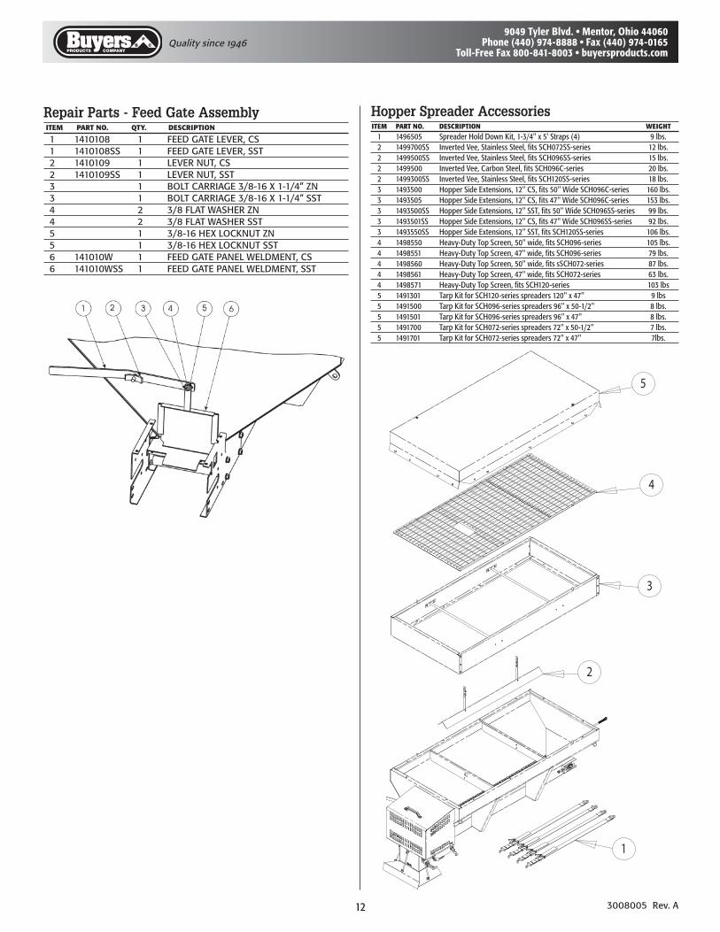
1 1410108 1 FEED GATE LEVER, CS 1 1410108SS 1 FEED GATE LEVER, SST 2 1410109 1 LEVER NUT, CS 2 1410109SS 1 LEVER NUT, SST 3 1 BOLT CARRIAGE 3/8-16 X 1-1/4” ZN 3 1 BOLT CARRIAGE 3/8-16 X 1-1/4” SST 4 2 3/8 FLAT WASHER ZN 4 2 3/8 FLAT WASHER SST 5 1 3/8-16 HEX LOCKNUT ZN 5 1 3/8-16 HEX LOCKNUT SST 6 141010W 1 FEED GATE PANEL WELDMENT, CS 6 141010WSS 1 FEED GATE PANEL WELDMENT, SST
ItEM PARtNO. qtY. DESCRIPtION
Repair Parts - Feed Gate AssemblyITEM PARTNO. DESCRIPTION WEIGHT 1 1����0� SpreaderHoldDownKit,1-�/�"x�'Straps(�) �lbs. � 1����00SS InvertedVee,StainlessSteel,fitsSCH0��SS-series 1�lbs. � 1����00SS InvertedVee,StainlessSteel,fitsSCH0��SS-series 1�lbs. � 1����00 InvertedVee,CarbonSteel,fitsSCH0��C-series �0lbs. � 1����00SS InvertedVee,StainlessSteel,fitsSCH1�0SS-series 1�lbs. � 1����00 HopperSideExtensions,1�"CS,fits�0"WideSCH0��C-series 1�0lbs. � 1����0� HopperSideExtensions,1�"CS,fits��"WideSCH0��C-series 1��lbs. � 1����00SS HopperSideExtensions,1�"SST,fits�0"WideSCH0��SS-series ��lbs. � 1����01SS HopperSideExtensions,1�"CS,fits��"WideSCH0��SS-series ��lbs. � 1�����0SS HopperSideExtensions,1�"SST,fitsSCH1�0SS-series 10�lbs. � 1�����0 Heavy-DutyTopScreen,�0"wide,fitsSCH0��-series 10�lbs. � 1�����1 Heavy-DutyTopScreen,��"wide,fitsSCH0��-series ��lbs. � 1�����0 Heavy-DutyTopScreen,�0"wide,fitssSCH0��-series ��lbs. � 1�����1 Heavy-DutyTopScreen,��"wide,fitsSCH0��-series ��lbs. � 1�����1 Heavy-DutyTopScreen,fitsSCH1�0-series 10�lbs � 1��1�01 TarpKitforSCH1�0-seriesspreaders1�0"x��" �lbs � 1��1�00 TarpKitforSCH0��-seriesspreaders��"x�0-1/�" �lbs. � 1��1�01 TarpKitforSCH0��-seriesspreaders��"x��" �lbs. � 1��1�00 TarpKitforSCH0��-seriesspreaders��"x�0-1/�" �lbs. � 1��1�01 TarpKitforSCH0��-seriesspreaders��"x��" �lbs.
Hopper Spreader Accessories
5
4
3
2
1