Installation Manual - renumaterials.com Dowel Opening In ... With four Gracies™ per panel it is...
23
1 236 E Arrow Hwy, Covina, Ca 91722 949-246-4177 Installation Manual
Transcript of Installation Manual - renumaterials.com Dowel Opening In ... With four Gracies™ per panel it is...

1
236 E Arrow Hwy, Covina, Ca 91722 949-246-4177
Installation Manual

2
Table of Contents
History
What is Rapid Roadway
Types of Pavement
Measure/Survey
Saw cut and Removal
Drilling Dowel Opening In Existing Pavement
Base Preparation
Grout Containment
Panel Prep
Panel Installation
Level Panels
Engage Dowels
Bedding Grout
Fill Grout
Final Steps

3
History:
California started experimenting with jointed precast concrete pavement in
2010 with an installation of 800+/- panels on the 10 freeway. District 7 (Los
Angeles and Ventura Counties) Maintenance started using jointed precast for
repairs that same year.
Rapid Roadway™ is the result of a unique collaboration of a contractor,
concrete pavement expert and grout supplier. It was developed in District 7 as
an improvement over other existing systems. Rapid Roadway™ provided an
easier and quicker method to install precast pavement over other widely used
precast concrete pavement systems.
Rapid Roadway™ has allowed Southern California contractors to more than
triple their nightly installation versus other precast pavement systems.
The increased production as well as the longer life that reinforced precast
pavement provides has allowed Rapid Roadway™ to be the preferred repair
method for California DOT Maintenance in Los Angeles and Ventura counties
for the past 2 years. It is also being used by San Bernardino, Riverside and
Orange counties. Rapid Roadway has also been installed in Utah and is
pending on a project in Hawaii.

4
What is Rapid Roadway™?
Rapid Roadway™ is a precast concrete pavement system that consists of 5
equally important parts. The Gracie Leveling Lift™, the Barra Glide™ Load
Transfer System, Performance Plus™ Bedding and Fill Grouts, Grout
Containment™ and a quality precast concrete manufacturer.
Gracie Leveling Lift™: The Gracie™ is a patented insert that serves a dual
purpose. With four Gracies™ per panel it is used as a lift insert to handle the
precast panels. After the panel has been placed the same insert is used as a
leveler. With its attached bottom plate and a leveling screw the panel can be
leveled to match existing grades and super elevations.
Gracie™ prior to pouring Panels with 4 Gracies™ and leveling screw

5
Barra Glide™ Load Transfer System: The Barra Glide™ is a patented center
slot sliding dowel load transfer system. Because of its unique design the
largest top opening is 1 1/8” x 9 ¼” which prevents any possibility that the
1½” x 18” dowel will be dislodged. After the dowel has been engaged the
dowel is encased top and bottom by reinforced precast concrete. Because the
dowel is not cast into the concrete panel, the panel can be manufactured up to
12’ lay lengths. The center slot design ensures that the fill grout will not be
contaminated by the bedding grout.

6
Performance Plus™ RH Non-Sanded Bedding Grout: RH bedding grout is a
rapid hardening, non-shrink, very free flowing, zero bleed, sand aggregate
free, cementitious grout. This product is specifically designed as a pumpable,
bedding support for under precast concrete panels. RH Bedding Grout exhibits
rheological fluid properties allowing all small voids between the sub-grade
and precast concrete panels to be filled.
Performance Plus™ RH Latex Fill Grout: RH Latex Fill Grout is a rapid
hardening, non-shrink, free flowing, zero bleed, sanded, cementitious grout. It
is a blend of specialty cements and admixtures designed to provide flow and
shrinkage compensation. RH Latex Fill Grout is sanded, non-metallic and
contains no chlorides. Performance Plus™ Copolymer Latex is added to the
Fill Grout to increase adhesion and to improve overall performance.
Grout Containment: Grout Containment™ is a patent pending method that
serves a dual purpose. It serves as a bond break between the bedding grout
and the existing base and it also contains the bedding grout from migrating
under existing pavement.

7
Quality Precast Concrete Manufacturer: A successful Rapid Roadway™
installation cannot be accomplished without a qualified precast manufacturer.
The manufacturer needs to possess the internal quality control to be able
manufacture the precast slabs that meet the required tolerances. We
recommend that all precast manufacturing facilities are either NPCA or PCI
certified.

8
Types of Pavement:
Precast Jointed Concrete Pavement (PJCP): PJCP is for permanent
continuous lane replacement. Panels are designed for a 40 year life. When
installing multiple lanes panels as wide as 26’-6” may be used. If panels are
over 15’ wide pre-stressed panels must be used. Two panels may be used in
lieu of the single wide panel for multiple lanes, but requires a longitudinal
construction joint or keyway between adjoining panels. Skewed panels are
required on curved installations per Caltrans standard “Panel Skew
Dimension” table.
Individual Precast Slab Replacement (IPSR): IPSR is for shorter repair
installations. IPSR is produced in single lane widths only. Width is 2” wider
than existing lane. No longitudinal construction joint required for multiple
lane side by side installations. Skewed panels are required on curved
installations per Caltrans standard “Panel Skew Dimension” table. Normal lay
length is 12’.
Because of the Barra Glide’s™ sliding bar design PJCP and IPSR are normally
produced in 12’ lay lengths. Widths of 15ft and under can be reinforced with
either a rebar design or pre-stressed design. Widths over 15ft require pre-
stress design.

9
Layout:
Measurement: The goal on all layouts should be to keep the panel variation
to a minimum. A standard panel lay length should be established and when
feasible all layouts should be set to multiples of that length. By keeping the lay
length standard it will simplify production and installation. On shorter runs,
normally IPSR, the layout can be done with a 100ft tape measure and a 90
degree laser. For longer continuous runs, normally PJCP, it may be
advantageous to use a surveyor to layout.
The formula for the length of your layout is
L = (#panels *lay length in inches) + ((#panels -1) * 0.375”) + 1.5”
This formula will give you a lay length in inches
Your panels should be manufactured 2” wider than the existing lanes. Your
layout should be 1” wider than the precast panel. You should offset your
layout a minimum of 1” from the existing joint to ensure a straight cut.
The formula for the width of your layout is
W = panel width in inches + 1”
This formula will give you a width in inches
After your layout is complete you should measure your diagonals to ensure
that your layout is square.
Layout on Curved Installations: The layout on curves is similar to straight
layouts expect that you need to continually change your starting point. Use
the existing joint for reference. Establish your width at the starting point.
Mark your starting point off the existing joint. Measure 1-3 panel lengths,
depending on the severity of the radius, plus joint and mark a new start point
the same distance. Note that the panel lengths are longer on the outside of the
curve than on the inside. Check your width at every new point.
10
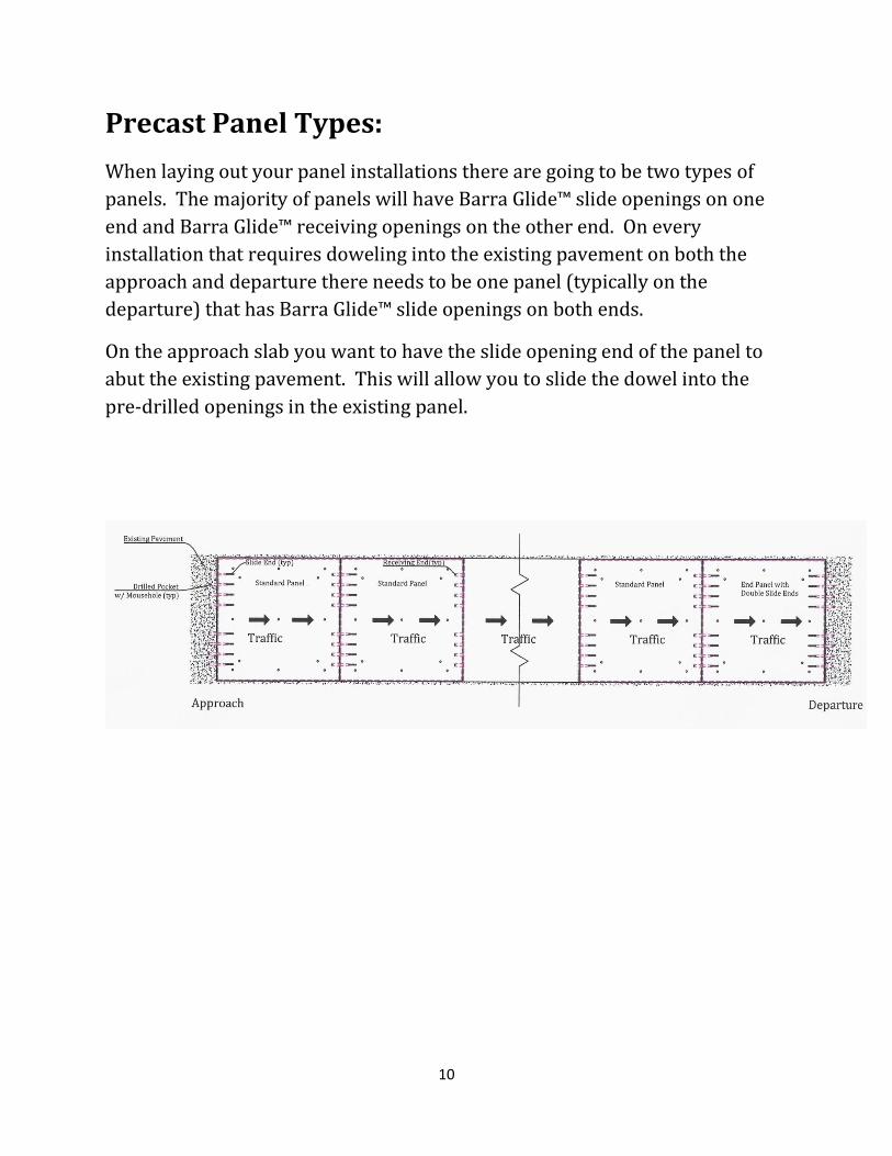
Precast Panel Types:
When laying out your panel installations there are going to be two types of
panels. The majority of panels will have Barra Glide™ slide openings on one
end and Barra Glide™ receiving openings on the other end. On every
installation that requires doweling into the existing pavement on both the
approach and departure there needs to be one panel (typically on the
departure) that has Barra Glide™ slide openings on both ends.
On the approach slab you want to have the slide opening end of the panel to
abut the existing pavement. This will allow you to slide the dowel into the
pre-drilled openings in the existing panel.

11
Saw cut and Removal:
Saw cut: Saw cut on your layout lines to ensure that your width is consistent.
Once you have cut the full width and length cut the length in to thirds (roughly
4ft wide). At the beginning of the layout a relief cut will make removal of the
4ft pull slab easier. Each 4ft pull slab has a 2in diameter hole for removal.
Panel Lift Pin

12
Once the 4ft pull slabs have been removed a slab bucket may be used to
remove the remaining existing slabs. The slab bucket does a minimal amount
of damage to the existing base reducing the amount of base repair. After
existing pavement has been removed the corners need to be squared up and
the undercut chipped away on each end.

13
Drill Existing Pavement For Dowel Slide:
After removal of existing pavement the existing pavement can be drilled to
accommodate load transfer dowels. Location and depth of drilled holes
should match the precast panels that are going to be placed. Drilled holes
should be large enough to except the dowel and allow enough space for fill
grout to completely encase the dowel. We recommend 2” for a 1.5” dowel.
Depth should be half the length of the dowel, 9” for standard 18” dowel. After
the horizontal 2” holes have been drilled, vertical holes needs to be drilled for
fill grout access. The vertical openings should be a minimum of ¾” and
located in the back half of the horizontal opening.

14
Base Preparation:
After removal of existing pavement the existing base needs to be evaluated.
What is the base composition? Lean base or gravel? Depth to base needs to
be compared to the precast panel thickness. The depth should allow a
minimum of 1/8” of space for grout, but should not exceed 1/2”. If existing is
a lean concrete base and extra depth is required then grinding will be
necessary. If base is too deep then a lean concrete rapid setting base (LCB)
will need to be placed. On existing gravel base only, prior to LCB placement
existing base must be properly compacted.
If LCB is not required the existing base must be level with no high spots. High
spots can create a pivot point on the precast panels prior to leveling and
grouting. If the pavement is opened to traffic prior to leveling and grouting,
(emergency situations only) these high points may cause panel cracking.
LCB Placement: There are numerous ways to ensure LCB depth and
levelness. Maximum aggregate size needs to smaller than the required
thickness of LCB. Whatever method that is used for LCB placement depth and
levelness must be ensured.

15
Grout Containment:
After the base has been placed the grout containment is placed over the LCB
to aid in curing. Once the LCB has reached 750psi strength the 6mil grout
containment sheet is placed tight against all sides. Reasonable effort should
be used to smooth out bubbles and wrinkles. The sheet needs to overlap on
the ends and the sides to preform correctly. When runs are longer or wider
than a single sheet the overlap needs to follow the flow of the grout.

16
Panel Preparation:
Precast panels need to be prepped prior to installation. Prepping includes
cleaning of the Barra Glide™ voids, installation of the Barra Plugs™, attaching
the Barra Pads™ to the dowels, greasing the dowel bars, installing dowel bars
in the slide end of the panel and attaching the expansion foam on the sides of
the panel. Panel prep can be done prior to delivery, but measures must be
made to protect the expansion foam in place and to ensure that the dowels
remain in the slide end.
If panel prep is done onsite, deliveries should arrive approximately 1 hour
prior to setting to ensure ample time for preparation.
Onsite Panel Prep

17
Panel Installation:
After the grout containment has been placed and the lean base has reached a
minimum of 750psi panel installation can begin. Panels are placed directly on
the base. It is ok to drive the placement equipment on non-grouted panels. It
is important to compress the transverse foam between panels. Transverse
and longitudinal joint widths should not exceed ½”.
Typical Joints Panel Placement

18
Panel Leveling:
After the setting crew has progressed the leveling of the panels can begin. The
first step is to release the bottom plate of the Gracie™, this is accomplished
with a ¾” steel rod and an 8lb
hammer.
Place rod into the Gracie™
opening and hammer until you
feel the plate release. This is a
critical step. The leveling bolts
will not work if the bottom plate
is not released.
After the bottom plates have been
release the leveling bolts are
installed. An impact wrench is
used to level the panels to the
surrounding profiles using the
transverse joint as the primary gauge.

19
Engage Dowels:
Once the panels have been leveled the dowels can be engaged from the slide
end of the Barra Glide™ into the receiving end. This is accomplished by
placing a thin metal rod behind the dowel bar and simply pushing the dowel
into the receiving end.
Dowel Prior to Slide
Dowel Slide

20
Bedding Grout:
Once the panels have been leveled grouting commences. You want to start
the grout process from an uphill position. The multiple grout ports allow
observation of the grout flow to ensure that all panels are fully bedded. On
larger installations multiple grout crews may be used.
The Performance Plus bedding grout is a Rapid Hardening Material. The
bedding grout is manufactured in such a way as to give the contractor the
optimal set time and early strength.
The set time is controlled with Performance Plus™ Set Control on site. There
are three conditions that effect the set time, ambient temperature, water
temperature and material temperature. After recording these temperatures
the set control is added into the mixer at the proper dosage. It is best to add
the set control after the second bag has started mixing. After mixing, a sample
of the mixed bedding grout is taken immediately and the temperature is
checked. For the best results the bedding grout should have a temperature in
the low to mid 70˚ F range out of the mixer. If the mixed bedding grout is
lower or higher in temperature than the low to mid 70˚ F range the set control
dosage is adjusted up or down.
Performance Plus™ Products will have a tech on site to train grouting
personnel on the dosage rate of the set control at the start of the project and
as needed.

21
Grout Truck With Dual ChemGrout Mixers
Grout Wand

22
Fill Grout:
After the panels have been leveled and the dowels have been engaged the
Barra Glide™ openings may be filled with Performance Plus RH™ fill grout.
Mix Performance Plus™ Latex Fill Grout per bag instructions making sure the
latex fill grout is fluid enough to totally encapsulate the dowel bar. The latex
fill grout has to be placed as soon as mixing is completed and as quickly as
possible. Fill half of the dowel bar slot allowing any entrapped air to escape
and then return and top off the remaining half of the slot before the latex
grout starts to set. If the latex grout settles below the top of the precast panel
it will need to be topped off again.

23
Final Steps:
After the bedding grout has reached 2000psi (approximately 30minutes)
remove the leveling bolts. Cut the overlapping grout containment. Seal all
joints and open to traffic.
THE END
www.RapidRoadway.com
January 1, 2015