INSTALLATION MANUAL CONVENI-PACK - UK | Daikin · Installation manual CONVENI-PACK ... English 1...
21
INSTALLATION MANUAL English Deutsch Français Español Italiano Portugues Nederlands Outdoor Unit (LRYEQ16AY1(E)) CONVENI-PACK Installation manual CONVENI-PACK Installationsanleitung CONVENI-PACK Manuel d’installation CONVENI-PACK Manual de instalación CONVENI-PACK Manuale di installazione CONVENI-PACK Installatiehandleiding CONVENI-PACK Manual de instalação CONVENI-PACK
Transcript of INSTALLATION MANUAL CONVENI-PACK - UK | Daikin · Installation manual CONVENI-PACK ... English 1...

INSTALLATION MANUAL
English
Deutsch
Français
Español
Italiano
Portugues
Nederlands
Outdoor Unit(LRYEQ16AY1(E))
CONVENI-PACK
Installation manualCONVENI-PACK
InstallationsanleitungCONVENI-PACK
Manuel d’installationCONVENI-PACK
Manual de instalaciónCONVENI-PACK
Manuale di installazioneCONVENI-PACK
InstallatiehandleidingCONVENI-PACK
Manual de instalaçãoCONVENI-PACK


English 1
LRYEQ16AY1(E) CONVENI-PACK Installation manual
CONTENTS1. FIRST OF ALL ......................................................................... 1
1-1 Safety Precautions............................................................ 11-2 Special Notice of Product.................................................. 21-3 Disposal Requirements..................................................... 2
2. BEFORE INSTALLATION........................................................ 22-1 Standard Supplied Accessories ........................................ 22-2 Example of System Configuration..................................... 32-3 Indoor Unit Constraints ..................................................... 3
3. SELECTION OF LOCATION ................................................... 34. HANDLING THE UNIT ............................................................. 45. PLACING THE UNIT................................................................ 56. REFRIGERANT PIPING .......................................................... 5
6-1 Selection of Piping Material .............................................. 66-2 Protection Against Contamination
when Installing Pipes ........................................................ 76-3 Pipe Connection................................................................ 76-4 Drier Installation ................................................................ 76-5 Connecting the Refrigerant Piping .................................... 7
7. FIELD WIRING ........................................................................ 97-1 Example of Wiring Entire System ................................... 117-2 Procedure for Incoming Wiring ....................................... 117-3 Procedure for Power Supply Wiring................................ 127-4 Procedure for Wiring Inside Units ................................... 13
8. INSPECTION AND PIPE INSULATION................................. 148-1 Air Tight Test/Vacuum Drying ......................................... 148-2 Thermal Insulation Work ................................................. 148-3 Checking of Device and Installation Conditions.............. 15
9. CHECKS AFTER WORK COMPLETION .............................. 1510. REFRIGERANT REPLENISHMENT...................................... 1511. TEST RUN ............................................................................. 16
1. FIRST OF ALL• This document is an installation manual for the Daikin CONVENI-
PACK. Before installing the unit, read this manual thoroughly, and following the instructions contained in it. After installation, do a test run to make sure the unit runs properly, and then explain how to operate and take care of the unit to the customer, using the operation manual.
• Lastly, make sure the customer keeps this manual, along with the operation manual, in a safe place.
• This manual does not describe how to install the indoor unit. Refer to the installation manual included with the indoor unit for that.
1-1 Safety PrecautionsPlease read these “Safety precautions” carefully before installing the CONVENI-PACK and be sure to install it correctly. After completing installation, conduct a trial operation to check for faults and explain to the customer how to operate the CONVENI-PACK and take care of it with the aid of the operation manual. Ask the customer to store the installation manual along with the operation manual for future reference.
Meaning of WARNING and CAUTION notices
WARNING.....Failure to follow these instructions properly may result in personal injury or loss of life.
CAUTION ......Failure to observe these instructions properly may result in property damage or personal injury, which may be serious depending on the circumstances.
WARNING
• Ask your dealer or qualified personnel to carry out installation work.Do not attempt to install the CONVENI-PACK yourself. Improper installation may result in water leakage, electric shocks or fire.
• Maintenance personnel of the manufacturer or equivalent skilled personnel should install this unit.
• Install the CONVENI-PACK in accordance with the instructions in this installation manual.Improper installation may result in water leakage, electric shocks or fire.
• When installing the unit in a small room, take measures against to keep refrigerant concentration from exceeding allowable safety limits in the event of refrigerant leakage. Contact the place of purchase for more information. Excessive refrigerant in a closed ambient can lead to oxygen deficiency.
• Be sure to use only the specified accessories and parts for instal-lation work.Failure to use the specified parts may result in the unit falling, water leakage, electric shocks or fire.
• Install the CONVENI-PACK on a foundation strong enough to withstand the weight of the unit.A foundation of insufficient strength may result in the equipment falling and causing injury.
• Carry out the specified installation work after taking into account strong winds, typhoons or earthquakes.Failure to do so during installation work may result in the unit fall-ing and causing accidents.
• Make sure that a separate power supply circuit is provided for this unit and that all electrical work is carried out by qualified person-nel according to local laws and regulations and this installation manual.An insufficient power supply capacity or improper electrical con-struction may lead to electric shocks or fire.
• Make sure that all wiring is secured, the specified wires are used, and that there is no strain on the terminal connections or wires.Improper connections or securing of wires may result in abnormal heat build-up or fire.
• When wiring the power supply and connecting transmission wir-ing, position the wires so that the control box lid can be securely fastened. Improper positioning of the control box lid may result in electric shocks, fire or the terminals overheating.
• If refrigerant gas leaks during installation, ventilate the area immediately.Toxic gas may be produced if the refrigerant gas comes into con-tact with fire.
• After completing installation, check for refrigerant gas leakage.Toxic gas may be produced if the refrigerant gas leaks into the room and comes into contact with a source of fire, such as a fan heater, stove or cooker.
• Be sure to switch off the unit before touching any electrical parts.• Do not directly touch refrigerant that has leaked from refrigerant
pipes or other areas, as there is a danger of frostbite. • Do not allow children to climb on the outside unit and avoid plac-
ing objects on the unit. Injury may result if the unit becomes loose and falls.
• Be sure to earth the CONVENI-PACK.Do not earth the unit to a utility pipe, lightning conductor or telephone earth lead. Imperfect earthing may result in electric shocks or fire.A high surge current from lightning or other sources may cause damage to the CONVENI-PACK.
• Be sure to install an earth leakage breaker.Failure to install an earth leakage breaker may result in electric shocks or fire.
CAUTION
• While following the instructions in this installation manual, install drain piping to ensure proper drainage and insulate piping to pre-vent condensation.Improper drain piping may result in indoor water leakage and property damage.

2 English
• Install the indoor and outdoor units, power cord and connecting wires at least 1 meter away from televisions or radios to prevent picture interference and noise.(Depending on the incoming signal strength, a distance of 1 meter may not be sufficient to eliminate noise.)
• Do not install the CONVENI-PACK in the following locations:1. Where there is a high concentration of mineral oil spray or
vapor (e.g. a kitchen).Plastic parts will deteriorate, parts may fall off and water leak-age could result.
2. Where corrosive gas, such as sulphurous acid gas, is produced.Corroding of copper pipes or soldered parts may result in refrigerant leakage.
3. Near machinery emitting electromagnetic radiation.Electromagnetic radiation may disturb the operation of the control system and result in a malfunction of the unit.
4. Where flammable gas may leak, where there is carbon fiber or ignitable dust suspensions in the air, or where volatile flamma-bles such as paint thinner or gasoline are handled.Operating the unit in such conditions may result in fire.
5. Vehicles, ships, or other places that generate vibration or cause the CONVENI-PACK to move.The CONVENI-PACK may malfunction or cause oxygen defi-ciency accidents as a result of refrigerant leakage.
6. Places with excessive voltage fluctuations.The CONVENI-PACK may malfunction.
7. Places where fallen leaves accumulate or weeds grow thick.8. Places that become small animals’ shelter.
Small animals coming in contact with electrical parts can cause malfunctions, smoke, or ignition.
• The CONVENI-PACK is not intended for use in a potentially explo-sive atmosphere.
1-2 Special Notice of Product[CLASSIFICATION]• This CONVENI-PACK comes under the term “appliances not
accessible to the general public”.• Follow the showcase to be connected for the climate class.
(EN60335-2-89)[EMC CHARACTERISTICS]This System is a class A product. In a domestic environment this product may cause radio interference in which case the user may be required to take adequate measures.[REFRIGERANT]This System use R410A refrigerant.
CAUTION
This unit is already filled with a certain amount of R410A.Never open liquid and gas shutoff valve until the step Specified in “9. CHECKS AFTER WORK COMPLETION”.
• The refrigerant R410A requires strict cautions for keeping the sys-tem clean, dry and tight.Read the chapter “REFRIGERANT PIPING” carefully and follow these procedures correctly.A. Clean and dry
Foreign materials (including mineral oils such as SUNISO oil or moisture) should be prevented from getting mixed into the system.
B. TightTake care to keep the system tight when installing.R410A does not contain any chlorine, does not destroy the ozone layer, and does not reduce the earth’s protection against harmful ultraviolet radiation.R410A can contribute slightly to the greenhouse effect if it is released.
• Since R410A is a mixed refrigerant, the required additional refrig-erant must be charged in its liquid state. If the refrigerant is charged in a state of gas, its composition changes and the system will not work properly.
• Be sure to perform refrigerant replenishment. Refer to “9. CHECKS AFTER WORK COMPLETION” and the label of instructions on refrigerant replenishment on the cover surface of the control box,
Important information regarding the refrigerant usedThis product contains fluorinated greenhouse gases covered by the Kyoto Protocol. Do not vent gases into the atmosphere.Refrigerant type : R410A
GWP (1)
value : 1975(1)
GWP = global warming potential* Values are indicated in F-gas regulations (EC) No.842/2006, Annex I, Parts 1 and 2.Please fill in with indelible ink,
the factory refrigerant charge of the product, the additional refrigerant amount charged in the field and + the total refrigerant charge
on the refrigerant charge label supplied with the product.
The filled out label must be adhered in the proximity of the product charging port (e.g. onto the inside of the service cover).
[DESIGN PRESSURE]Since design pressure is 3.8MPa or 38bar (for R407C units : 3.3MPa or 33bar), the wall thickness of pipes should be more carefully selected in accordance with the relevant local and national regula-tions.
1-3 Disposal RequirementsDismantling of the unit, treatment of the refrigerant, oil and eventual other parts, should be done in accordance with the relevant local and national regulations.
2. BEFORE INSTALLATION
CAUTION
• When installing the indoor unit, refer to the installation manual provided for the indoor unit.
• Optional accessories are required for the installation of the prod-uct. Refer to the information on optional accessory.
2-1 Standard Supplied AccessoriesThe following accessories are included. The storage location of the accessories is shown in the figure.
NoteDo not throw away any of the accessories until installation is complete.
Name Clamp (1) Clamp (2)Gas side
accessory pipe (1)
Gas side accessory
pipe (2)
Quantity 11 pcs. 2 pcs. 1 pc. 1 pc.
Shape
Small
3
56
2
1
4 1 factory refrigerant charge of the product : see unit name plate
2 additional refrigerant amount charged in the field
3 total refrigerant charge
4 Contains fluorinated greenhouse gases covered by the Kyoto Protocol
5 outdoor unit
6 refrigerant cylinder and manifold for charging

English 3
2-2 Example of System Configuration
1 Operation manual 2 Installation manual 3 Clamps4 Accessory pipes (Installed on bottom frame)
2-3 Indoor Unit Constraints (Refrigeration and Freezer)
• The design pressure for the indoor unit is 2.5 MPa or more.• Install an R410A mechanical thermostatic expansion valve on
each indoor unit.• Insulate the feeler block of the mechanical thermostatic expan-
sion valve.• Install an R410A solenoid valve on the primary side of the
mechanical thermostatic expansion valve (Max. operating differ-ential pressure of 3.5 MPa [35 bars] or over) described above for each indoor unit.
• Install a filter on the primary side of the solenoid valve described above for each indoor unit. Determine the filter mesh count based on the size specified by the solenoid valve and mechanical ther-mostatic expansion valve being used.
• Route the path to the indoor unit heat exchanger so that the flow of refrigerant is from top to bottom.
• When installing a number of indoor units, be sure to install them at the same level.
• Use either off-cycle defrosting or electric heater defrosting as the defrosting type. Hot-gas defrosting models cannot be used.
3. SELECTION OF LOCATIONSelect a location for installation that meets the following conditions. Get the customer’s permission.
1. There is no danger of fire due to leakage of inflammable gas.
2. Select the location of the unit in such a way that neither the dis-charged air nor the sound generated by the unit disturb anyone.
3. The foundation is strong enough to support the weight of the unit and the floor is flat to prevent vibration and noise generation.
4. The piping length between the outdoor unit and the indoor unit may not exceed the allowable piping length. (Refer to “6. REFRIGERANT PIPING”)
5. Locations where the unit’s suction vent and outlet vent do not gen-erally face the wind. Wind blowing directly into the suction or outlet vents will interfere with the unit’s operation.If necessary, install some kind of obstruction to block the wind.
6. The space around the unit is adequate for servicing and the min-imum space for air inlet and air outlet is available. (See the “Installation Space Examples” for the minimum space requirements.)
Installation Space Examples• The installation space requirement shown in the following figure is
a reference for cooling operation when the outdoor temperature is 32°C. If the design outdoor temperature exceeds 32°C or the heat load exceeds maximum capacity in all the outdoor unit, take an even large space on the intake shown in the following figure.
• During installation, install the units using the most appropriate of the patterns shown in the following figure for the location in ques-tion, taking into consideration human traffic and wind.
• If the number of units installed is more than that shown in the pat-tern in the following figure, install the units so there are no short circuits.
• As regards space in front of the unit, consider the space needed for the local refrigerant piping when installing the units.
• If the work conditions in the following figure do not apply, contact your dealer or Daikin directly.
NameLiquid side accessory
pipe (1)Liquid side accessory
pipe (2)
Quantity 1 pc. 1 pc.
Shape
NameLiquid side accessory
pipe (3)
Liquid side accessory
pipe (4)Others
Quantity 1 pc. 1 pc. 1 pc. about each item
Shape
• Operation manual• Installation manual• Declaration of con-
formity (PED)• “ADDITIONAL REF.
CHARGE” label
Name Outdoor unit Booster unit
Shape
Name
Indoor unit
Air-conditionerRefrigeration
Blower coil Showcase
Shape
Name
Indoor unitControl panel
(Defrost)
Warning panel
Remote controller (for air-
conditioner)
Freezer
Blower coil Showcase
Shape
1, 2, 3
4

4 English
NOTE) For Patterns 1 and 2• Wall height for front side no higher than 1500 mm.• Wall height on the suction side no higher than 500 mm.• Wall height for sides – no limit• If the height is exceeded the above, calculate h1 and h2 shown
in the figure on next page, and add h1/2 to the service space of front side and h2/2 to the service space of suction side.
CAUTION
1. An inverter CONVENI-PACK may cause electronic noise gener-ated from AM broadcasting. Examine where to install the main CONVENI-PACK and electric wires, keeping proper distances away from stereo equipment, personal computers, etc.Particularly for locations with weak reception, ensure there is a distance of at least 3 meters for indoor remote controllers, place
power wiring and transmission wiring in conduits, and ground the conduits.
2. When installing in a locations where there is heavy snowfall, implement the following snow measures.• Ensure the base is high enough that intakes are not clogged
by snow.• Mount a snow protection hood (optional accessory)• Remove the rear intake grille to prevent snow from accumulat-
ing on the fins.
3. If condensate may drip on downstairs (or walkway) depending on the floor condition, take a measure such as the installation of cen-tral drain pan kit (sold separately).
4. The refrigerant R410A itself is nontoxic, nonflammable and is safe. If the refrigerant should leak however, its concentration may exceed the allowable limit depending on room size. Due to this it could be necessary to take measures against leakage. See “Engineering Data” for details.
4. HANDLING THE UNIT1. Decide on the transportation route.
2. If a forklift is to be used, pass the forklift arms through the large openings on the bottom of the unit.
1 Opening (large)2 Fork 3 Fixed screws of transportation clasp4 Transportation clasp (yellow)If hanging the unit, use a cloth sling to prevent damaging the unit. Keeping the following points in mind, hang the unit following the procedure shown in the following figure.• Use a sling sufficiently strong to hold the mass of the unit.• Use 2 belts of at least 8m long.• Place extra cloth in the locations where the casing comes in
contact with the sling to prevent damage.• Hoist the unit making sure it is being lifted at its center of gravity.
1 Belt sling2 Patch cloth3 Belt sling4 Patch cloth5 Opening
3. After installation, remove the transportation clasp (yellow) attached to the large openings.
NoteApply a filler cloth on a fork to prevent coating of the bottom frame from coming off and rust from occurring when bringing in the unit with anti-corrosion treatment type using a forklift.
≥10 ≥10 ≥10≥20
≥10≥20
≥50≥100
≥50≥100
≥200≥400 ≥400
≥50 ≥50
≥200
≥300
≥300
≥300
≥500
≥100
≥500
≥300
≥500
≥100
≥500
< When installed as a single unit >(Pattern 1) NOTE)
(Pattern 2) NOTE) (Pattern 2) NOTE)
(Pattern 3) (Pattern 3)
(Pattern 1) NOTE)< When installed in serial >
Front side Front side
Front side
Front side
Front side
Front side
No limit to wall height
No limit to wall height
Servi
ce sp
ace
of su
ction
side
Servi
ce sp
ace
of fro
nt sid
e
Servi
ce sp
ace
of su
ction
side
Servi
ce sp
ace
of fro
nt sid
eSe
rvice
spac
e of
sucti
on si
deSe
rvice
spac
e of
front
side
Servi
ce sp
ace
of su
ction
side
Servi
ce sp
ace
of fro
nt sid
e
A
B1500
500
h2
Fro
nt s
ide
Service space
Service space
Suc
tion
side
h1
h1 = A (Actual height) – 1500h2 = B (Actual height) – 500X = 500 + h1/2 or overY = 300 + h2/2 or over(Y = 100 + h2/2 or over)[Values in parentheses are for pattern 2]
≥1500
≥150
0≥1
500
≥1500
≥1500
Branch switch, overcurrent breaker(Earth leakage breaker)
Branch switch, overcurrent breaker(Earth leakage breaker)
Control panelWarning panel
Showcase (mm)
1
24
3
1 23
4
5

English 5
5. PLACING THE UNIT• Make sure the unit is installed level on a sufficiently strong base to
prevent vibration and noise.• The base should be bigger around than the width of the unit’s legs
(66 mm), and should support the unit.If protective rubber is to be attached, attach it to the whole face of the base.
• The height of the base should be at least 150mm from the floor.• Secure the unit to its base using foundation bolts. (Use four com-
mercially available M12-type foundation bolts, nuts, and washers.)• The foundation bolts should be inserted 20 mm.
Note• When installing on a roof, make sure the roof floor is strong
enough and be sure to water-proof all work.• Make sure the area around the machine drains properly by setting
up drainage grooves around the foundation.Drain water is sometimes discharged from the outdoor unit when it is running.
• If the CONVENI-PACK is of brine damage resistant or heavy brine dam-age resistant type, use nuts provided with resin washers to secure the prod-uct to the foundation bolts (see the illustration on the right-hand side).The rustproof effect of the nut will be lost if the coatings on the tightening portions of the nuts come off.
6. REFRIGERANT PIPINGTo Piping Work Contractors• Never open the shutoff valve until the steps specified in “7. FIELD
WIRING” and “8-3 Checking of Device and Installation Condi-tions” of piping.
• Do not use flux at the time of brazing and connecting refrigerant pipes. Use phosphorous copper brazing filler metal (BCuP-2), which does not require flux. Chlorine-based flux causes piping corrosion. Furthermore, if fluoride is contained, the flux will have adverse influences on the refrigerant piping line, such as the dete-rioration of refrigerating machine oil.
CAUTION
• All field piping must be installed by a licensed refrigeration tech-nician and must comply with relevant local and national regula-tions.
[Precautions for reuse of existing refrigerant piping / heat exchangers]
Keep the following points in mind for the reuse of existing refrig-erant piping / heat exchangers.A malfunction may result if there is deficiency.• Do not use the existing piping in the following cases. Perform new
piping instead.• The piping is different in size.• The strength of the piping is insufficient.• The compressor of the CONVENI-PACK previously used
caused a malfunction.An adverse influence of residual substances, such as the oxi-dation of refrigerant oil and the generation of scale, is consid-ered.
• If the indoor unit or outdoor unit is disconnected from the piping for a long time.The intrusion of water and dust into the piping is considered.
• The copper pipe is corroded.• The refrigerant of the CONVENI-PACK previously used was
other than R410A (e.g., R404A / R507 or R407C). The contamination of the refrigerant with heterogeneity is con-sidered.
• If there are welded connections midway on the local piping, make gas leakage checks on the welded connections.
• Be sure to insulate the connection piping.The liquid and gas pipe temperatures are as follows:Liquid pipe arrival minimum temperature
20°C (Air-conditioning side) 5°C (Refrigeration side)
Gas pipe arrival minimum temperature: 0°C (Air-conditioning side)–20°C (Refrigeration side)
In the case of thickness insufficiency, add additional insulation material or renew the existing insulation material.
• Renew the insulation material if the insulation material is degraded.
Keep the following points in mind for the reuse of existing heat exchangers• Units with insufficient design pressure (since this product is an
R410A unit) require a lower-stage design pressure of 2.5 MPa [25 bars].
• Units for which the path to the heat exchanger has been routed so that the flow of refrigerant is from bottom to top.
• Units with copper tubing or fan corrosion.• Units that may be contaminated with foreign matter such as rub-
bish or other dirt.
20≥100
≥100
≥100
≥100
≥100
≥100
Corner-hole foundation
Independent foundation
Beam foundation (horizontal)
Beam foundation (vertical)
Center of the product Center of the product
Base form
1240
1102
729
765
(Dep
th o
f pro
duct
)
631
(Inn
er d
imen
sion
of
the
base
)76
5 or
mor
e(O
uter
dim
ensi
on
of th
e ba
se)
Foundation bolt point (4-15 × 22.5)
(Unit : mm)
Base width and base bolt positions
Resin washers

6 English
6-1 Selection of Piping Material• Make sure that the inner side and outer side of the piping used is clean and free of contaminants, such as sulphur, oxide, dust, chips, oil and fat, and water.
It is desirable that the maximum oil adhesion in the piping is 30 mg per 10 m.• Use the following type of refrigerant piping.
Material: Seamless phosphorus deoxidized copper tube (C1220T-O for a maximum outer diameter of 15.9 mm and C1220T-1/2H for a mini-mum outer diameter of 19.1 mm)
Refrigerant piping size and wall thickness: Decide the size and thickness from the following table.(This product uses R410A. The withstand pressure of O type may be insufficient if it is used for piping with a minimum diameter of 19.1 mm. Therefore, be sure to use 1/2 H type with a minimum thickness of 1.0 mm.If O type is used for piping with a minimum diameter of 19.1 mm, a minimum thickness of 1.2 mm will be required. In that case, be sure to perform the blazing of each joint.)
• Be sure to perform piping work within the range specified in the following table.
Max. permissible one-way piping length (equivalent length)
Max. difference in height between indoor and outdoor units
Difference in height between unit cooler and showcase
unit below outdoor unit
unit above outdoor unit
a + b + c + d1 ≤ 130m (d1 is d or e whichever is longer)
a2 + b2 + e1 ≤ 130m (e1 is d2 or e2 whichever is longer)
b + c + d1 ≤ 30m (d1 is d or e whichever is longer)
b2 + e1 ≤ 30m (e1 is d2 or e2 whichever is longer)
H1, H2 ≤ 35m (Note)
H1, H2 ≤ 10m
H3 ≤ 5m
H4 ≤ 0.5m
Max. branch piping length (actual length)
Difference in height between air-conditioner indoor units
Note: A trap is required at 5 m intervals from outdoor unit.
⟨Refrigerant piping length⟩
⟨Refrigerant piping size⟩(Refrigeration)
Outdoor unit sidePiping size (mm)
Liquid pipe Gas pipe50m or less 50~130m 50m or less 50~130m
Piping between branching areas(B, b, C, c)
Piping between branching areas and each unit
Select the piping from the following table in accordance with the total capacity of indoor units connected downstream.
No size after branching can exceed the size of any upstream piping.
φ9.5 × 0.8 (O type) φ12.7 × 0.8 (O type)
φ12.7 × 0.8 (O type) φ6.4 × 0.8 (O type)
φ9.5 × 0.8 (O type)φ15.9 × 1.0 (1/2H type)φ19.1 × 1.0 (1/2H type)φ22.2 × 1.0 (1/2H type)φ25.4 × 1.0 (1/2H type)
φ25.4 × 1.0 (1/2H type) φ28.6 × 1.2 (1/2H type)
Total capacity of indoor units after branchingLess than 6.0 kW6.0 kW or over and less than 9.9 kW9.9 kW or over and less than 14.5 kW14.5 kW or over and less than 18.5 kW18.5 kW or over
Gas pipe size Liquid pipe size
(Air-condition)
Outdoor unit sidePiping size (mm)
Liquid pipe Gas pipe50m or less 50~130m 50m or less 50~130mm
Piping between branching areas(B2, b2)
Piping between branching areas and each unit
Select the piping from the following table in accordance with the total capacity of indoor units connected downstream.
No size after branching can exceed the size of any upstream piping.
φ9.5 × 0.8 (O type) φ12.7 × 0.8 (O type)
φ9.5 × 0.8 (O type)
φ12.7 × 0.8 (O type)
φ15.9 × 1.0 (1/2H type)φ19.1 × 1.0 (1/2H type)φ22.2 × 1.0 (1/2H type)
φ25.4 × 1.0 (1/2H type) φ28.6 × 1.2 (1/2H type)
Total capacity of indoor units after branchingLess than 16.0 kW16.0 kW or over and less than 22.4 kW22.4 kW or over and less than 28.0 kW
Gas pipe size Liquid pipe size
Piping between outdoor unit and first branch (A, a)
Piping between outdoor unit and first branch (A2, a2)
In case of no connection with booster unit Outdoor unit
ShowcaseUnit
cooler
Airconditioner
Liquid pipingGas piping
Difference in height
NoteWhen connecting the booster unit, refer to the installation manual provided for the booster unit.
If the size of the connection pipe of the indoor unit exceeds that of the branch pipe shown in the table above, enlarge the size of the connection pipe near the indoor unit before connecting it.
If the size of the connection pipe of the indoor unit exceeds that of the branch pipe shown in the table above, enlarge the size of the connection pipe near the indoor unit before connecting it.

English 7
6-2 Protection Against Contamination when Installing Pipes
Protect the piping to prevent moisture, dirt, dust, etc. from entering the piping.
NoteExercise special caution to prevent dirt or dust when passing piping through holes in walls and when passing pipe edges to the exterior.
6-3 Pipe Connection• Be sure to perform nitrogen permutation or nitrogen blow when brazing.
Brazing without performing nitrogen permutation or nitrogen blow into the piping will create large quantities of oxidized film on the inside of the pipes, adversely affecting valves and compressors in the refrigerating system and preventing normal operation.
• The pressure regulator for the nitrogen released when doing the brazing should be set to 0.02 MPa (about 0.2kg/cm
2:Enough to
feel a slight breeze on your cheek).
NoteDo not use anti-oxidants when brazing the pipe joints.Residue can clog pipes and break equipment.
6-4 Drier Installation
CAUTION
This product requires that a drier be installed on liquid piping on site.(Operating the unit without a drier installed may result in equipment failure.)
Select a drier from the following chart:
• Connect the drier to liquid pipe on the refrigeration side.• Install the drier in a horizontal orientation wherever possible.• Install the drier as close to the outdoor unit as possible.• Remove the drier cap immediately before brazing (to prevent
absorption of airborne moisture).• Follow instructions in the drier instruction manual concerning drier
brazing.• Repair any burning of drier paint that occurs during drier brazing.
Contact the manufacturer for more information about paint for repair use.
• Flow direction is specified for some type of the dryer.Set the flow direction according to the operation manual of the dryer. (Liquid refrigerant flows from the outdoor unit to the indoor unit.)
6-5 Connecting the Refrigerant Piping
CAUTION
• In addition to gas and liquid shutoff valves, this unit has a mainte-nance shutoff valve (see diagram below).
• Do not operate the maintenance shutoff valve*.(The factory setting for the maintenance shutoff valve is “open.” During operation, always leave this valve in the open position. Operating the unit with the valve in the closed position may cause the compressor to fail.)
1. Directions to bring out the pipesThe local interunit piping can be connected either forward or to the sides (taken out through the bottom) as shown in the following figure.When passing out through the bottom, use the knock hole in the bottom frame.
Precautions when knocking out knock holes• Open knock hole in the base frame by drilling the 4 concave
around it with a 6mm bit.
• Be sure to avoid damaging the casing• After knocking out the holes, we recommend you remove any
burrs and paint them using the repair paint to prevent rusting.• When passing electrical wiring through the knock holes, protect
the wiring with a conduit or bushings, making sure not to damage the wiring.
Place Installation period Protection method
OutdoorMore than a month Pinch the pipe
Less than a monthPinch or tape the pipe
Indoor Regardless of the period
ModelRequired dryer core (recommended type)
LRYEQ16AY1160g (100% molecular sieve equivalent)(DML164/DML164S : Danfoss made)
Refrigerant pipe
Regulator
Handy valve
Taping
Nitrogen
Nitrogen
Location to be brazed
Liquid side shutoff valve (provided with service port)
Gas side shutoff valve (provided with service port)
* Maintenance shutoff valve
* Maintenance shutoff valve
Right-side connection
Front connection
Left-side connection
Knock hole
Concave section (4 places)
Drill

8 English
2. Removing Pinch PipingIn the case of connecting refrigerant piping to the outdoor unit, remove the span piping as in the following procedure.Refer to “Operation method of shutoff valve” for handling of the shutoff valve.
WARNING
Disconnect the pinch piping after collecting the refrigerant gas in the piping.The piping may be blown off and injury may result by melting the brazing filler metal unless the refrigerant gas in the piping is all col-lected.
Operation Method of Shutoff ValvesFollow the instructions below when operating each shutoff valve.
CAUTION
• Do not open the shutoff valve until the steps specified in “8-3 Checking of Device and Installation Conditions” is com-pleted.Do not leave the shutoff valve opened without turning the power on, otherwise refrigerant may be condensed in the compressor and the insulation of the main power supply circuit may be degraded.
• Be sure to use an exclusive tool to handle the shutoff valve. The shutoff valve is not of back sheet type. Excessive force imposed may break the valve.
• Use a charge hose when using the service port.• Make sure that there is no refrigerant gas leakage after the valve
cover and cap are securely tightened.
⟨Tightening torque⟩Check with the following table the sizes of shutoff valves incorporated by each model and the tightening torque values of the respective shutoff valves.
Shutoff valve sizes
⟨Opening method⟩1. Remove the valve cover and turn the shaft anticlockwise with a
hexagon wrench.2. Turn the shaft until the shaft stops.3. Tighten the valve cover securely. Refer to the above table for the
tightening torque according to the size.
⟨Closing method⟩1. Remove the valve cover and turn the shaft clockwise with a hexa-
gon wrench.2. Tighten the shaft until the shaft comes in contact with the sealing
part of the valve.3. Tighten the valve cover securely. Refer to the above table for the
tightening torque according to the size.
⟨Handling Precautions for Valve Cover⟩• Be careful not to damage the sealing part.• At the time of mounting the valve cover, apply a screw lock agent
to the screw thread.• Do not apply a screw lock agent (for flare nut use) to the sealing
part.• Be sure to tighten the valve cover securely after operating the
valve. Refer to “Operation Method of Shutoff Valves” for the tightening torque of the valve.
Procedure 1Confirm the shutoff valve is closed.
Procedure 4Melt the brazing material with a burner and remove the pinch piping (large) after the gas in the pinch piping is discharged.
Procedure 2Connect a charge hose to the service port of the liquid side and gas side shutoff valves and remove the gas from the pinch piping.
Procedure 3Cut off the pinch piping (small) with an appropriate tool, such as a pipe cutter, and open the cross section to check that there is no residual oil.Note: If oil comes out of the cross section, cut off the pinch piping (large) with a pipecutter and remove the pinch piping.
Pinch piping
Service portLiquid side and gas side shutoff valves
Piping on product side
Service portCharge hose
On-site piping
Pinch piping (Large)
Pinch piping (Small)Cut off
Liquid side shutoff valve φ9.5
Gas side shutoff valve φ25.4
Shutoff valve sizes
Tightening torque N•m (closes clockwise)
Shaft (valve body) Valve cover Service port
φ9.5 5.4~6.5Hexagon
wrench: 4mm13.5~16.5
11.5~13.9
φ25.4 27.0~33.0Hexagon
wrench: 8mm22.5~27.5
Service port
Valve cover
Hexagon hole
ShaftSealing part
Screw threadApply a screw lock agent
Sealing partNot apply a screw lock agent
Shutoff valve Part of mounting the valve cover.
Valve cover

English 9
⟨Handling Precautions for Service Port⟩• Work on the service port with a charge hose provided with a push-
ing rod.• At the time of mounting the cap, apply a screw lock agent to the
screw thread.• Do not apply a screw lock agent (for flare nut use) to the sealing
part.• Be sure to tighten the cap securely after the work. Refer to “Oper-
ation Method of Shutoff Valves” for the tightening torque of the cap.
CAUTION
Apply a screw lock agent to the valve cover mount and the screw thread of the service port.Otherwise, dew condensation water will intrude inside and freeze. Therefore, refrigerant gas leakage or a compressor malfunction may result from the cap deformation or damage.
3. Connecting refrigerant piping to outdoor units
If connected to the frontRemove the shutoff valve cover to connect.
When connected at lateral side (bottom)Remove the knock hole on the bottom frame and route the piping under the bottom frame.
CAUTION
• Check that the on-site piping does not come in contact with other piping, the bottom frame, or side plate of the product.
⟨Precautions for Piping⟩Perform piping branching with the following conditions kept in mind.
• At the time of branching the liquid piping, use a Y-joint and branch it horizontally. This will prevent an uneven flow of refrigerant.
• At the time of branching gas piping, use a T-joint and branch it so that the branched piping will be located above the main piping (see the illustration below). This will prevent the stay of refrigerant oil in the indoor unit not in operation.
• Use a T-joint for the gas refrigerant branch and connect from the top of the main piping.
• Make sure that the horizontal portion of the gas piping slants downward to the outdoor unit (see the illustration above).
• If the outdoor unit is located above, make a trap on the gas pipe at 5 m intervals from outdoor unit. This will ensure the smooth returning of oil in the piping slanting upward.
7. FIELD WIRINGTo Electric Engineering Contractors• Be sure to install an earth leakage breaker. The product incorpo-
rates inverter equipment. In order to prevent the malfunctioning of the earth leakage breaker, make sure that the earth leakage breaker withstands harmonic interference.
• Do not operate the CONVENI-PACK until refrigerant piping work is completed, or otherwise the compressor will malfunction.
• Do not remove any electrical components such as thermistors or sensors when connecting power supply wires or transmission wires. The compressor may malfunction if the CONVENI-PACK is operated with such electrical components removed.
CAUTION
• All field wiring and components must be installed by a licensed electrician and must comply with relevant local and national reg-ulations.
• Be sure to use a dedicated power circuit. Never use a power sup-ply shared by another appliance.
• Never install a phase advancing capacitor. As this unit is equipped with an inverter, installing a phase advancing capacitor will not only deteriorate power factor improvement effect, but also may cause capacitor abnormal heating accident due to high-frequency waves.
• Only proceed with wiring work after blocking off all power.• Always ground wires in accordance with relevant local and
national regulations.• This machine includes an inverter device. Connect earth and
leave charge to eliminate the impact on other devices by reducing noise generated from the inverter device and to prevent leaked current from being charged in the outer hull of the product.
• Do not connect the ground wire to gas pipes, sewage pipes, light-ning rods, or telephone ground wires.Gas pipes: can explode or catch fire if there is a gas leak.Sewage pipes: no grounding effect is possible if hard plastic pip-ing is used.Telephone ground wires and lightning rods: dangerous when struck by lightning due to abnormal rise in electrical potential in the grounding.
Sealing partNot apply a screw lock agent
Screw threadApply a screw lock agent
Cap
[2] Gas side shutoff valve(Air-conditioner)
Liquid side accessory pipe (2)Gas side accessory pipe (2)
Brazing
[3] Gas side shutoff valve(Refrigerator)
[4] Liquid side shutoff valve(Refrigerator)
Liquid side accessory pipe (1)
Gas side accessory pipe (1)
[1] Liquid side shutoff valve(Air-conditioner)
[2] Gas side shutoff valve(Air-conditioner)
[3] Gas side shutoff valve(Refrigerator)
[4] Liquid side shutoff valve(Refrigerator)[1] Liquid side shutoff valve
(Air-conditioner)
Gas side accessory pipe (3)
Gas side accessory pipe (4)
Gas side piping (field supply)
Brazing Brazing
Liquid side accessory pipe (3)
Liquid side accessory pipe (4)Knock holePunch the knock hole
Liquid side piping (field supply)
Liquid piping
Horizontal surface ±30˚ or less
A-arrow viewA
Y-joint
Gas piping
T-joint
Main piping
Indoor unit side
Outdoor unit side
Branch pipingMake the piping slant downward
Branch piping
Make the piping slant downward
Main pipingMake the piping slant downward
T-joint

10 English
• Be sure to install an earth leakage circuit breaker.This unit uses an inverter, so install the earth leakage circuit breaker that be capable of handling high harmonics in order to prevent malfunctioning of the earth leakage circuit breaker itself.
• Earth leakage circuit breaker which are especially for protecting ground-faults should be used in conjunction with main switch or fuse for use with wiring.
• Electrical wiring must be done in accordance with the wiring dia-grams and the description herein.
• Do not operate until refrigerant piping work is completed.(If operated before complete the piping work, the compressor may be broken down.)
• Never remove thermistor, sensor or etc. when connecting power wiring and transmission wiring.(If operated with thermistor, sensor or etc. removed, the compres-sor may be broken down.)
• This product have reversed phase protection detector that only works when the power is turned on. If there exists black out or the power goes on and off which the product is operating, attach a reversed phase protection circuit. Running the product in reversed phase may break the compressor and other parts.
• Attach the power wire securely. Introducing power with a missing N-phase or with a mistaken N-phase will break the unit.
• Never connect the power supply in reversed phase. The unit can not operate normally in reversed phase.If you connect in reversed phase, replace two of the three phases.
• Make sure the electrical unbalance ratio is no greater than 2%. If it is larger than this, the unit’s lifespan will be reduced.If the ratio exceeds 4%, the unit will shut down and an malfunction code will be displayed on the indoor remote controller.
• Connect the wire securely using designated wire and fix it with attached clamp without applying external pressure on the termi-nal parts (terminal for power wiring, terminal for transmission wir-ing and earth terminal).
• Install a switch that allows you to switch all poles from the main power supply.

English 11
7-1 Example of Wiring Entire System
Note• Use conduit for power supply wiring.• Make sure the weak electric wiring (i.e. for the remote controller,
between units, etc.) and the power wiring do not pass near each other, keeping them at least 50 mm apart.Proximity may cause electrical interference, malfunctions, and breakage.
• Be sure to connect the power wiring to the power wiring terminal block and secure it as described in “7-2 Procedure for Incoming Wiring”.
• Do not connect the power supply to the terminal block for the transmission wiring for warning, alarm, operation output, and remote operation switch. Otherwise the entire system will be dam-aged.
• Transmission wiring should be secured as described in “7-3 Procedure for Power Supply Wiring”.
• Secure wiring with clamp such as insulation lock ties to avoid con-tact with piping.
• Shape the wires to prevent the structure such as the control box lid deforming. And close the cover firmly.
7-2 Procedure for Incoming Wiring• Route high-voltage wiring (power supply wiring, earth wires, and
warning/alarm/operation wiring) through wiring openings located on the side or front of the unit (knock holes) or on the bottom frame (knock holes).
• Route low-voltage wiring (for remote operating switches) through wiring openings (knock holes) located on the front of the unit or through wiring intakes.
Note• Open the knock holes with a hammer or the like.• After knocking out the holes, we recommend you remove any
burrs and paint them using the repair paint to prevent rusting.
Timer for refrigerationTimer for freezer
Relay
Alarm panel
Warning outputCaution output
AC220-240V(Note 2)
Branch switchOvercurrentcircuit breaker
Refrigeration operating output (Note 2)
Freezer operation output
Indoorunit
Booster unit
Remote switch(Note 1)
Remotecontroller
In-Out Out-Out
Thermostat for inner temperature adjustmentDefrost completion thermostatSolenoid valve
Electromagnetic contactor(Defrost heater)Defrost lamp
Integrated heat control board (Field supply)
Timer for freezer
Timer for refrigeration
For freezerFor refrigerator
ST controller
Showcase interface
Warninginput
Sensorinput
Freezer showcase
Refrigeration unit cooler
Refrigeration showcase
Refrigeration showcase
3 phase 380-415VEarth leakage circuit breaker(High-frequency type)(For earth fault, overload and short-circuit protection)
AC 220-240VEarth leakage circuit breaker(High-frequency type)(For earth fault, overload and short-circuit protection)
(Note 1)Remote switch
Earth leakage circuit breaker(For earth fault, overload and short-circuit protection)
E1H
Outdoor unit
Caution inputWarning input
Note:1. For Remote switch, use non-voltage contact for microcurrent (not more than 1mA, 12VDC)Note:2. Total capacity for warning, alarm : 0.5A or less at AC 220 to 240V.
Capacity for operation output : 0.5A or less at AC 220 to 240V.
(Note 2)
Through-hole coverCut the shaded area
Electric wiring label(Rear side of control box lid)
ConduitPiping outlet
High-voltage wiring
Low-voltage wiring

12 English
• When passing electrical wiring through the knock holes, protect the wiring with a conduit or bushings, making sure not to damage the wiring.
• If small animals might enter the unit, block off any gaps (hatching parts) with material (field supply).
7-3 Procedure for Power Supply Wiring⟨Procedure for Power Supply Wiring⟩
1 Power supply (3 phase 380~415)2 Overcurrent circuit breaker (earth leakage circuit breaker), all pole
disconnection switch3 Earth wire4 Power supply terminal block5 Mount insulation sleeves6 Fix the power supply wiring for phases L1, L2, L3, and N, respec-
tively, with the provided clamp (1) to the resin clamp.7 Fix the earth wire to the power supply wire (phase N) with the pro-
vided clamp (1).8 Earth wire
Perform wiring so that the earth wire will not come in contact with lead wires of the compressor. Otherwise, noise generated may have a bad influence on other equipment.
9 Ground terminal10 • When two wires are connected to a single terminal, connect
them so that the rear sides of the crimp contacts face each other.
• Also, make sure the thinner wire is on top, securing the two wires simultaneously to the resin hook using the accessory clamp (1).
Power circuit, safety device, and cable requirements (X1M~X4M terminal block)• A power circuit (see the following table) must be provided for con-
nection of the unit. This circuit must be protected with the required safety devices, i.e. a main switch, a slow blow fuse on each phase and an earth leakage circuit breaker.
• When using residual current operated circuit breakers, be sure to use a high-speed type (1 second or less) 200mA rated residual operating current.
• Use copper conductors only.• Use insulated wire for the power cord.• Select the power supply cable type and size in accordance with
relevant local and national regulations.• Specifications for local wiring are in compliance with IEC60245.• Use wire type H05VV when protected pipes are used.• Use wire type H07RN-F when protected pipes are not used.
Point for attention regarding quality of the public electric power supply
This equipment complies with respectively:
EN/IEC61000-3-11(1)
provided that the system impedance Zsys is less than or equal to Zmax andEN/IEC61000-3-12
(2) provided that the short-circuit power Ssc is
greater than or equal to the minimum Ssc value
at the interface point between the user’s supply and the public sys-tem. It is the responsibility of the installer or user of the equipment to ensure. by consultation with the distribution network operator if nec-essary, that the equipment is connected only to a supply with respec-tively:
Zsys less than or equal to Zmax andSsc greater than or equal to the minimum Ssc value.
(1) European/International Technical Standard setting the limits for voltage changes.Voltage llucruations and flicker in public low-voltage supply sys-tems for equipment with rated current ≤ 75A
(2) European/International Technical Standard setting the limits for harmonic currents produced by equipment connected to public low-voltage systems with input current > 16A and ≤ 75A per phase.
Operation output wiring connections• Connect operation output wiring to the X2M terminal block and
clamp as indicated by the following diagram:
X2M wire specifications
Knockout hole(For low-voltage wiring)
Knockout hole(For high-voltage wiring)
Burr
NL 1 L 2 L 3
B
1
2
3
4
5
67
910
8
Terminal block Crip style terminal Wire: narrow
Clamp (1)
Wire: thick
Resin hook
Phase and frequency
VoltageMinimum
circuit amp.
Recom-mended
fuses
LRYEQ16AY1 φ3, 50Hz 380-415V 35.2A 40A
Zmax (Ω) minimum Ssc value
LRYEQ16AY1 0.24 1038KVA
Electric wire thickness 0.75~1.25mm2
Max. wiring length 130m
Clamp (1)

English 13
CAUTION
• Refer to the “7-1 Example of Wiring Entire System” by all means when connecting the operation output wiring.A compressor failure may result if the operating output wiring is not connected.
Warning, alarm wiring connections• Connect warning, alarm wiring to the X4M terminal block and
clamp as indicated by the following diagram:
X4M wire specifications
Note: Be sure to insulate the mating equipment.
Remote operating switch wiring connections• When installing a remote operating switch, clamp as indicated by
the following diagram:
X3M wire specifications
CAUTION
• For Remote switch, use non-voltage contact for microcurrent (not more than 1mA, 12VDC)
• If the remote operating switch will be used to start and stop the unit, set the operating switch to “REMOTE”.
<Precautions for Terminal Connections>• Be sure to use ring-type crimp-style terminals provided with insu-
lation sleeves.• Use specified electric wires for the wiring and secure the wiring so
that external force will not be imposed on the terminal block.
• Use an appropriate screwdriver to tighten the terminal screws.Small-sized screwdriver will damage the screw heads and cannot tighten the screws properly.
• Do not tighten the terminal screws in excess, otherwise the screws may be damaged.
• Refer to the following table for the tightening torque values of the terminal screws.
• Take out the earth wire from the notch of the cup washer and lay the wire carefully so that other wires will not be caught by the washer. Otherwise, the earth wire may not contact sufficiently and the earthing effect of the wire may be lost.
• Do not finish strand wire with solder.
7-4 Procedure for Wiring Inside Units• Referring to the following figure, secure and wire the power and
transmission wiring using the accessory clamp (1), (2), and (3).• Lay the ground wire so that it will not come in contact with the lead
wires of the compressor. Other equipment will be adversely affected if the ground wire comes in contact with the lead wires of the compressor.
• Make sure all wiring do not contact to the pipes (hatching parts in the figure).
• The transmission wiring must be at least 50 mm away from the power wiring.
• After wiring work is completed, check to make sure there are no loose connections among the electrical parts in the control box.
1 Conduit2 Perform wiring carefully so that the wiring will not come in contact
with the port3 When routing high-voltage wiring (power supply wiring, earth
wires, and warning/alarm/operation output wiring) from the left side
4 Connecting local piping5 Power supply terminal block (X1M)6 X2M terminal block for operation output7 Earth terminal block8 When routing high-voltage wiring (power supply wiring, earth
wires, and warning/alarm/operation output wiring) from the right side
9 When routing high-voltage wiring (power supply wiring, earth wires, and warning/alarm/operation output wiring) from the front
10 Remote operating switch terminal block (X3M)11 When routing remote operating switch wiring through a wiring
opening12 Separate by at least 50 mm13 Stay
Electric wire thickness 0.75~1.25mm2
Max. wiring length 130m
Electric wire thickness 0.75~1.25mm2
Max. wiring length 130m
Mount insulation sleeves
Fix the wiring with the provided clamp (1)
X3M 21
Secure remote operating switch wiring to the resin block using a clamp (field supply).
Crimp-style terminal
Insulating sleeve
Power wire
Screw size Tightening torque (N•m)
M8 (Power supply terminal block)5.5 - 7.3
M8 (Earth)
M4 (X2M) 2.39 - 2.91
M3.5 (X3M) 0.79 - 0.97
Crimp-style terminal
Cup washer
Cut out section
6
8
1112917
3
2
1
13
15 5
4
14
16
10
7
14 English
14 Perform wiring carefully so that the sound insulation of the com-pressor will not come off
15 Support16 Fixed to the rear side of the support with the provided clamp (2)17 Fixed to the rear side of the support with the provided clamp (2)
CAUTION
On completion of electrical work, check that there are no disconnected connectors or terminals of any electrical parts in the control box.
8. INSPECTION AND PIPE INSULATIONFor piping work contractor, electrical work contractor, and trial run workers
• Never open the shutoff valve until the insulation measurement of the main power supply circuit is finished. The measured insulation value will become lower if the measurement is made with the shutoff valve opened.
• On completion of inspection and refrigerant charging, open the shutoff valve. The compressor will malfunction if the CONVENI-PACK is operated with the shutoff valve closed.
8-1 Air Tight Test/Vacuum DryingRefrigerant is enclosed in the unit.Be sure to keep both liquid and gas shutoff valves closed at the time of an airtight test or vacuum drying of the local piping.
[For piping work contractor]On completion of piping work, make the following inspection pre-cisely.• To ensure that the CONVENI-PACK withstand pressure properly
and prevent the penetration of foreign substances, be sure to use R410A-dedicated tools.
• Air tightPressurize the high-pressure section of the system (liquid piping) to 3.8 MPa (38 bar) and the low-pressure section of the system (gas piping) to the design pressure (*1) of the indoor unit (field supply) from the service port (*2) (do not exceed the design pres-sure). The system is considered to have passed if there is no decrease in the pressure over a period of 24 hours.If there is a decrease in the pressure, check for and repair leaks.
• Vacuum dryingConnect a vacuum pump to the service ports (*) of both the liquid and gas pipes for at least 2 hours and vacuum the unit down to –100.7 kPa or below. Then leave the unit for at least 1 hour at a pressure of –100.7 kPa or below and check that the vacuum gage reading will not rise. If the pressure rises, there is residual water in the system or the system has leakage.
*1 Contact the manufacturer in advance for more information about the design pressure of the indoor unit (field supply).
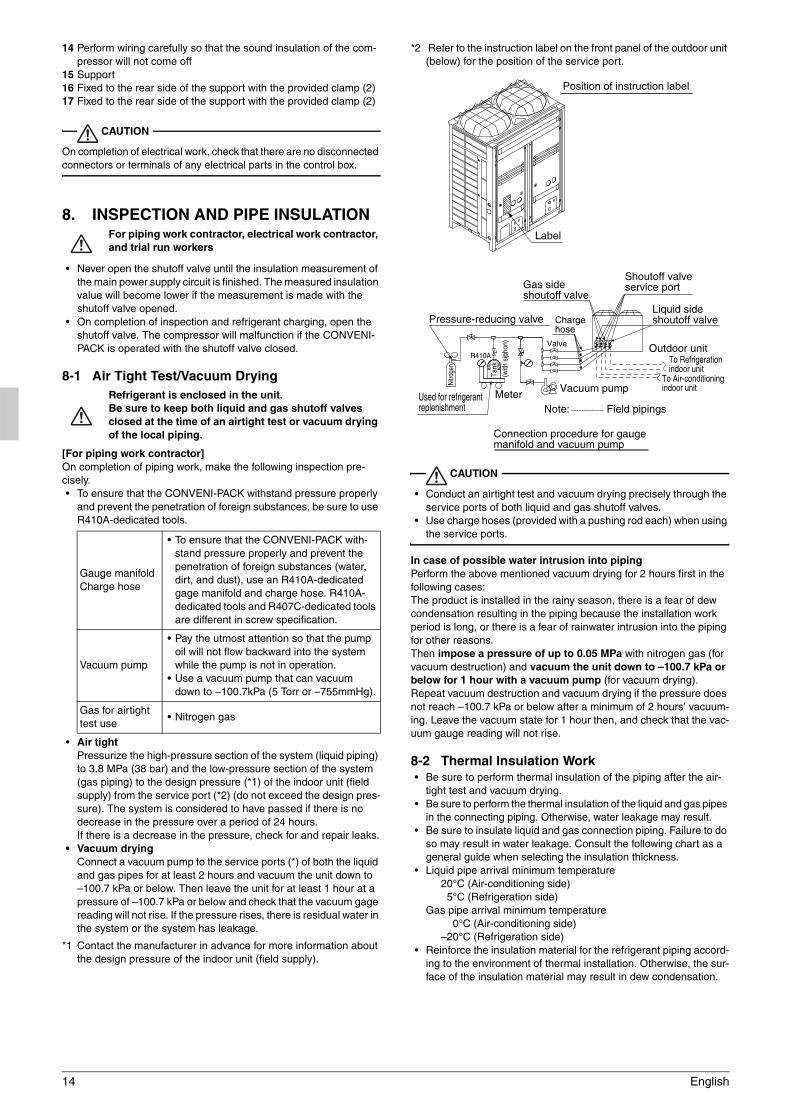
*2 Refer to the instruction label on the front panel of the outdoor unit (below) for the position of the service port.
CAUTION
• Conduct an airtight test and vacuum drying precisely through the service ports of both liquid and gas shutoff valves.
• Use charge hoses (provided with a pushing rod each) when using the service ports.
In case of possible water intrusion into pipingPerform the above mentioned vacuum drying for 2 hours first in the following cases:The product is installed in the rainy season, there is a fear of dew condensation resulting in the piping because the installation work period is long, or there is a fear of rainwater intrusion into the piping for other reasons.Then impose a pressure of up to 0.05 MPa with nitrogen gas (for vacuum destruction) and vacuum the unit down to –100.7 kPa or below for 1 hour with a vacuum pump (for vacuum drying).Repeat vacuum destruction and vacuum drying if the pressure does not reach –100.7 kPa or below after a minimum of 2 hours’ vacuum-ing. Leave the vacuum state for 1 hour then, and check that the vac-uum gauge reading will not rise.
8-2 Thermal Insulation Work• Be sure to perform thermal insulation of the piping after the air-
tight test and vacuum drying.• Be sure to perform the thermal insulation of the liquid and gas pipes
in the connecting piping. Otherwise, water leakage may result.• Be sure to insulate liquid and gas connection piping. Failure to do
so may result in water leakage. Consult the following chart as a general guide when selecting the insulation thickness.
• Liquid pipe arrival minimum temperature20°C (Air-conditioning side) 5°C (Refrigeration side)
Gas pipe arrival minimum temperature 0°C (Air-conditioning side)–20°C (Refrigeration side)
• Reinforce the insulation material for the refrigerant piping accord-ing to the environment of thermal installation. Otherwise, the sur-face of the insulation material may result in dew condensation.
Gauge manifoldCharge hose
• To ensure that the CONVENI-PACK with-stand pressure properly and prevent the penetration of foreign substances (water, dirt, and dust), use an R410A-dedicated gage manifold and charge hose. R410A-dedicated tools and R407C-dedicated tools are different in screw specification.
Vacuum pump
• Pay the utmost attention so that the pump oil will not flow backward into the system while the pump is not in operation.
• Use a vacuum pump that can vacuum down to –100.7kPa (5 Torr or –755mmHg).
Gas for airtight test use
• Nitrogen gas
Position of instruction label
Label
Pressure-reducing valve
Nitro
gen
Used for refrigerant replenishment
Tank
(with
sip
hon)
Meter Vacuum pump
Field pipingsNote:
Connection procedure for gauge manifold and vacuum pump
R410A
To Air-conditioningindoor unit
To Refrigerationindoor unit
Shoutoff valveservice port
Liquid sideshoutoff valve
Outdoor unit
Gas sideshoutoff valve
Valve
Charge hose

English 15
• If the dew condensation water on the shutoff valves is likely to flow to the indoor unit side through the clearance between the insula-tion material and piping because the outdoor unit is installed above the indoor unit or for some other reasons, perform appro-priate treatment such as the caulking of the joints (see the illus-trations below).
• Attach the cover of the piping outlet with a knock hole opened. If there is a feature of small animals intruding through the piping outlet, cover the piping outlet with a blocking material (field sup-ply) on completion of the steps of “10. REFRIGERANT REPLEN-ISHMENT” (see the illustrations below).Use the piping outlet for jobs required during the steps of “10. REFRIGERANT REPLENISHMENT” (e.g., a job of taking in the charge hose).
Note• After knocking out the holes, we recommend you remove burrs in
the knock holes and paint the edges and areas around the edges using the repair paint.
8-3 Checking of Device and Installation Condi-tions
Be sure to check the followings.
<For those doing electrical work>See “7-2 Procedure for Incoming Wiring”.
1. Make sure there is no faulty power wiring or loosing of a nut.See “7-3 Procedure for Power Supply Wiring”.
2. Has the insulation of the main power circuit deteriorated?Measure the insulation and check the insulation is above regular value in accordance with relevant local and national regulations.
<For those doing pipe work>
1. Make sure piping size is correct.See “6-1 Selection of Piping Material”.
2. Make sure insulation work is done. See “8-2 Thermal Insulation Work”.
3. Make sure there is no faulty refrigerant piping.See “6. REFRIGERANT PIPING”.
9. CHECKS AFTER WORK COMPLETION• Make sure the following works are complete in accordance with
the installation manual.Piping workWiring workAir tight test/Vacuum dryingInstallation work for indoor unitInstallation work for booster unit(In case of the booster unit connection)
10. REFRIGERANT REPLENISHMENT
For refrigerant filling contractor
Use R410A for refrigerant replenishment.The R410A refrigerant cylinder is painted with a pink belt.
Warning Electric Shock Warning
• Securely close the control box lid before turning power on.• Before turning power on, check through the inspection hole (on
the left-hand side) of the control box lid that the RUN switch is set to OFF.If the RUN switch is set to ON, the fan may rotate.
• Use an insulated rod to operate the push buttons via the EL. COMPO. BOX’s inspection door.There is a risk of electric shock if you touch any live parts, since this operation must be performed with the power on.
• Check the LED indicators on the PCB (A1P) of the outdoor unit through the inspection hole (on the right-hand side) of the control box lid after the outdoor unit is turned on (see the illustration).(The compressor will not operate for approximately 10 minutes after the outdoor unit and air-conditioning indoor unit are turned on.H2P will be turned off when in a condition to be able to operate a system. (H3P continues blink state)
WARNING
• Use protective gear (e.g., protective gloves and glasses) at the time of refrigerant filling.
• Pay attention to the rotation of the fan whenever the front panel is opened while working.The fan can rotate continuously for a while after the outdoor unit stops operating.
[Refrigerant Replenishment Work]
CAUTION
• Refer to the Operation Method of Shutoff Valves for the control method of the shutoff valves.
• Never replenish liquid refrigerant directly from a gas line. Liquid compression may cause the compressor to fail.
• Refer to the Service Manual for instructions on additional refriger-ant charging when indoor units are connected only to the air-con-ditioning equipment side or only to the refrigeration equipment side.
Liquid side shutoff valve
Gas side shutoff valve
Indoor/Outdoor interunit piping Insulation material
Coking, etc.
Liquid side pipingBlock
Gas side piping
Open a knock hole at
Piping lead-out hole lid
Inspection hole (left-hand side)
Inspection hole (right-hand side)
Control box
Inspection hole (left-hand side) (upper left-hand side of control box)
Inspection hole (right-hand side) (upper right-hand side of control box)
Control box lid
LED(H1~8P)
Lift up this tab and open the cover.
Inspection hole cover
REMOTE OFF ON
RUN switch (factory set: OFF)

16 English
• When the only indoor unit connected is an air-conditioner (when the showcase is not connected to the air-conditioning side), refer to the Service Manual for instructions on additional refrigerant charging.
1. The refrigerant must be noted for this product. Calculate the amount of refrigerant replenishment according to the label for the calculation of the amount of refrigerant replenishment.Procedures for calculating refrigerant charge amounts are described in page 18.
2. Take the following procedure for refrigerant replenishment.Refer to “8-1 Air Tight Test/Vacuum Drying” for the connection of the refrigerant cylinder.
(1) Turn on the indoor unit and control panel.Do not turn on the outdoor unit.
(2) Replenish refrigerant from the service port of the shutoff valve on the liquid side.
(3) If the calculated amount of refrigerant cannot be filled, take the following steps to operate the system and continue refrigerant replenishment.a. Open the gas shutoff valve all the way and adjust the opening
of the liquid shutoff valve (*1).b. [Warning/Electric Shock Warning]
Turn on the outdoor unit.c. [Warning/Electric Shock Warning]
Turn on the RUN switch of the outdoor unit and replenish refrigerant while the outdoor unit is in operation.
d. Turn off the RUN switch of the outdoor unit after the specified amount of refrigerant is replenished.
e. [Caution] Fully open the shutoff valves on the gas and liquid sides promptly. Otherwise, a piping explosion may result from liquid sealing.
*1 The cylinder’s internal pressure will drop when there is little refrig-erant remaining in the cylinder, making it impossible to charge the unit, even if the liquid shutoff valve opening is adjusted. In this sit-uation, replace the cylinder with one that has more refrigerant remaining.Additionally, if the piping length is long, replenishing while the liq-uid shutoff valve is fully closed may lead to activation of the pro-tection system, causing the unit to stop operation.
1. After the work is completed, apply a screw lock agent (for flare nuts) to the screws of the shutoff valves and service ports.Refer to the “Handling Precautions for Valve Cover” and “Handling Precautions for Service Port” in “6-5 Connecting the Refrigerant Piping” for the handling of the valve covers and service ports.
2. After the refrigerant replenishment is completed, fill out the item “total amount of refrigerant replenishment” on the label of instruc-tions on refrigerant replenishment of the outdoor unit with the actual amount of refrigerant replenishment.Refer to the illustration of the label pasting position for instructions on refrigerant replenishment (see the illustration on the above).
[Precautions for refrigerant cylinder]At the time of refrigerant filling, check whether the siphon tube is pro-vided. Then locate the cylinder so that the refrigerant will be filled in the state of liquid (see table below).R410A is a mixed refrigerant, the composition of which may change and the normal operation of the system may not be possible if the refrigerant is filled in the state of gas.
[Check through sight glass]
CAUTION
• Fully open the shutoff valves on the liquid and gas sides after the refrigerant replenishment is finished.The compressor will malfunction if the system is operated with the shutoff valves closed.
• Apply a screw lock agent to the screws of the valve cover mounting parts and service ports.(Otherwise, dew condensation water will intrude and freeze inside and cause cap deformation or damage, which may result in refrig-erant gas leakage or compressor malfunctions.)
11. TEST RUN
For test run operators
Do not operate the outdoor unit alone on a trial basis.When you connect a booster unit, refer to the installation manual attached to the booster unit before a test run.
Test run procedureUse the following procedure to perform a test run after installation work is complete for the entire system:
1. Fully open the shutoff valves on the gas and liquid side of the out-door unit.
2. Check that the electric accessory box lids of the outdoor unit, the indoor unit (air-conditioner, refrigeration showcase, refrigeration unit cooler) and the piping cover of the outdoor unit are closed. Then turn on the outdoor and indoor units (air conditioner, refrig-eration showcase, refrigeration unit cooler).
3. Turn on the operation switch from the inspection door of the out-door unit. (The outdoor fan rotates in about 10 minutes after the operation switch is turned on and the compressor starts.)
4. Push the ON/OFF button on the remote controller of the outdoor unit (air-conditioner) to operate the unit.
5. Check the sealing condition through the sight glass of the outdoor unit. In case of shortage of refrigerant, check if the refrigerant is charged to the specified level.
Label of instructions on refrigerant replenishment
Label pasting position
Control box
Cylinder provided with siphon tube.
Other cylinders
Stand the cylinder upright and fill the refrigerant.(There is a siphon tube inside, which makes it possible to replenish the refrigerant in the state of liquid without setting the cylinder upside down.)
Stand the cylinder upside down and fill the refrigerant.(Pay attention so that the cylinder will not topple down.)
Full of liquid A little foam flows.
Sealing state
Foam always comes out.
Refrigerant insufficiency
Sight glass

English 17
6. Check the following on each unit.
7. Be sure to turn off the operation switch before turning off the power.
Error diagnosis• Check the following if nothing is displayed on the remote controller
during the test run.
<Indoor unit (air-conditioner)>1. Is the power turned on?2. Is the wire broken or incorrectly wired (between the power, the
indoor unit and the remote controller)?3. Has the fuse on PCB melted?
• Take the following action if you find a malfunction code on the remote controller during the test run.
*1Set the operating switch to the “OFF” position to reset the power sup-ply and then return the switch to the “ON” position to restart the unit. If the problem persists, refer to the Service Manual.
• If you have changed the power wire and the transmission line, keep the power of the indoor unit (air conditioner, refrigeration showcase, refrigeration unit cooler) and the integrated heat con-trol board turned on, turn off the operation switch of the outdoor units and never fail to press the push button switch (BS5) on PCB (A1P) in the electric accessory box (right) of the outdoor unit for at least 10 seconds (Open the inspection door (right) on the upper right portion of the electric accessory box and operate the push button switch (BS5) using an insulating rod). (See the right figure.)
• Refer to the Service Manual for other malfunction codes.
CAUTION
• Do not disconnect the power supply for 1 minute after setting the operating switch to “ON”.Electric leak detection is performed for several seconds after the operating switch is set to “ON” and each compressor starts oper-ating, so disconnecting the power supply during that time will result in a false detection.
For dealers
• After the test run is finished, check that the piping cover and front panel are mounted.
• At the time of delivery to the customer, use the Operation Manual and fully explain the handling of the equipment.
• For precautions at the time of delivery, refer to the provided Instal-lation Manual for each unit as well.
Refrigeration showcase
Cold air should be blowing and the temper-ature should decrease to the preset level.The electronic expansion valve should be controlled on an appropriate superheated degree.The unit should start defrosting operation by the time set on the timer.
Refrigeration unit cooler
Cold air should be blowing and the temper-ature should decrease to the preset level.The electronic expansion valve should be controlled on an appropriate superheated degree.The unit should start defrosting operation by the time set on the timer.
Air-conditioner Cold air (or hot air) should be blowing.
Malfunction code
Defect at installation Action to be taken
E3, E4 Shutoff valves closedFully open the shutoff valves.
L4 The air passage is blocked.Remove obstacles blocking the air passage.
U1Reverse-phase of the power supply
Exchange two wires out of three power supply wires.
U2 Voltage drop Check the voltage drop.
U4, UFWrong wiring of transmis-sion lines between units
Check the connection of transmission lines between the outdoor unit and the air conditioner.
UAIn the case of system dis-crepancy
Check if the air conditioner is connected as should be assembled.
E2 Electric leak See *1.
Inspection door (right)(Upper right portion of the electric accessory box)

18 English
• This product must fill the refrigerant in the field.Calculate the amount of refrigerant replenishment according to the following points and note the amount of the refrigerant in a list shown below.
1. The amount of the refrigerant for the liquid piping is calculated from the liquid piping size and the piping length of the system.(Calculate the refrigerant additional charging quantity by rounding off to the number in 0.1kg.)
2. Total each piping size amount of the refrigerant.---(1)3. The amount of the refrigerant for the indoor unit of the refrigera-
tion is calculated from the capacity of the connected showcase as below table 1).1). Total all the refrigeration showcase capacities.2). Total all the freezer showcase capacities.3). Total all the blower coil capacities.4). Calculate the amount of the refrigeration by the total capacities
and the table 1) below of each indoor unit.4. The amount of the refrigerant for the each indoor unit of the Air-
conditioner calculated from the capacity of the connected indoor unit as below table 2).
5. Total each indoor unit amount of the refrigerant.---(2)6. Total the amount of the refrigerant of table below(1), (2), and (3).
---(4)7. Check sealing conditions through the sight glass at the time of
test run.If the sight glass has not been sealed yet (due to the shortage of refrigerant), charge additional refrigerant by 0.5kg.
Note• The upper limit quantity of refrigerant adjustment at the time of the
test run assumes 0.1 times of the quantity of refrigerant which calcu-lated from the capacity of connected indoor units.
8. Fill the amount of the refrigerant replenishment on this label.---(5)9. Calculate the amount of all refrigerant filling in this system.---(7)
Table 1) Capacity and amount of refrigerant of the indoor unit (Show-case and Blower coil)
Note1. Case of showcase, the condition of capacity (evaporating temper-
ature)Refrigeration :-10°CFrozen :-35°C
2. Case of blower coil, the condition of capacity is 10°C (Td).
Table 2) The amount of refrigerant of the indoor unit for air-condition-ing
*Calculate for each unit.
Figure 1)
Method of calculating "additional refrigerant charging quantity"
Liquid pipe size
(mm)
Refrigerant amount per 1m
(kg)
Pipe length(m)
Total amount of refrigerant
(kg)φ6.4 0.02 (a)φ9.5 0.06 (b)φ12.7 0.12 (c)φ15.9 0.19 (d)
(1) Subtotal [(a)+(b)+(c)+(d)]
Indoor unitTotal capacity (kW)
Amount of refrigerant (Refer to table 1 and 2)
Refrigeration showcase (A)Frozen showcase (B)Blower coil (C)Air-conditioning unit (D)
(2) Subtotal [(A)+(B)+(C)+(D)](3) Constant amount of additional filling 3.5(4) Total of the amount of refrigerant
replenishment [(1)+(2)+(3)](5) Amount of refrigerant replenishment at
the time of test run.(6) Amount of initial filling 11.5(7) Total additional charging amount
[(4)+(5)+(6)]
(5) ≤ (2) × 0.1
Indoor unit
Outdoor unitBlower coil
Booster unit
Refrigeration showcase
Frozen showcase
Total capacity of showcase or blower coil (*Note.)
Amount of refrigerant (kg)Showcase
Blower coilRefrigeration Frozen
Less than 5kW 1.1 1.4 0.6From 5kW to less than 10kW 2.3 3.2 1.2From 10kW to less than 15kW 3.4 5.2 1.7From 15kW to less than 20kW 4.6 2.320kW or more 5.9 3.0
HPKinds ofindoor unit
2.0 2.5 3.2 4.0 5.0 8.0 10.0
Round-flow cassette type (FXFQ)
0.5 0.9 0.9 0.9 1.0
Double-flow cassette type (FXCQ)
0.5 0.7 0.8 1.1
Ceiling built-in (FXSQ) 0.3 0.6 0.5 1.0 1.0Ceiling mounted duct type (FXMQ)
0.5 1.2 1.2 2.1 2.4
Ceiling suspended type (FXHQ)
0.8
Ceiling suspended cassette type (FXUQ)
0.9 1.1
Full of liquid
Bubbles come out at all times.
A few bubbles flow.
Sealed state ( ) Shortage of refrigerant ( )

3P248411-4B EM09A055 (1002) FS