SensaGuard Rectangular Flat Pack Installation...
12
SensaGuard TM Rectangular Flat Pack Installation Instructions Certifications IMPORTANT: SAVE THESE INSTRUCTIONS FOR FUTURE USE 440N-Z21SS2H-AS Note: Refer to Technical Specifications for Certification information and ratings. PN-114371 dir 10000182958 ver 00
Transcript of SensaGuard Rectangular Flat Pack Installation...

SensaGuard
TM
Rectangular Flat Pack
Installation Instructions
Certifications
IMPORTANT:
SAVE THESE INSTRUCTIONS FOR FUTURE USE
440N-Z21SS2H-AS
Note: Refer to Technical Specifications for Certification information and ratings.
PN-114371 dir 10000182958 ver 00
Table of Contents
Installation Instructions 3
Warnings 3
Technical Specification 3
Operating Characteristics 3
Outputs (internally fused) 3
Environmental 3
Protection 4
Dimensions 4
Mode of Operation 4
Status Indicators 4
Mounting Information 4
Nut Torque Specification 4
Minimum Distance Between Sensors 5
Misalignment Curve 5
Wiring Diagram 5
Recommended Mating Cable 5
Diagnostics 5
Troubleshooting 6
Application Wiring Examples 8
List of Recommended Relays 12
Maintenance 12
Repair 12
Declaration of Conformity 12
PN-114371 dir 10000182958 ver 00
2 SensaGuard
TM
Installation Instructions
ENGLISH: This instruction sheet is available in multiple languages at www.rockwellautomation.com/literature.
Select publication language and type "SensaGuard" in the search field.
GERMAN: Dieses Instruktionsblatt kann in mehreren Sprachen unter www.rockwellautomation.com/literature gelesen werden.
Bitte Ihre Sprache anwählen und "SensaGuard" im Suchfeld eintippen.
FRENCH: Ces instructions sont disponibles dans différentes langues à l'adresse suivante www.rockwellautomation.com/literature.
Sélectionner la langue puis taper “SensaGuard” dans le champ de recherche.
ITALIAN: La presente scheda d'istruzione è disponibile in varie lingue sul sito www.rockwellautomation.com/literature.
Selezionare la lingua desiderata e digitare "SensaGuard" nel campo di ricerca.
SPANISH: Puede encontrar esta hoja de instrucciones en varios idiomas en www.rockwellautomation.com/literature.
Seleccione el idioma de publicación y escriba "SensaGuard" en el campo de búsqueda.
PORTUGUESE: Esta folha de instruções está disponível em várias línguas em www.rockwellautomation.com/literature.
Seleccione a língua de publicação e entre com "SensaGuard" no espaço de busca.
POLISH: Ta kartka z instrukcjami jest dostepna w wielu jezykach na stronie: www.rockwellautomation.com/literature
Wybierz jezyk publikacji i wpisz w polu poszukiwania "SensaGuard".
Installation Instructions
Installation must be in accordance with the following steps and stated specifications and should be
carried out by suitable competent personnel. The unit is not to be used as a mechanical stop. Guard
stops and guides must be fitted. Adherence to the recommended maintenance instructions forms part
of the warranty.
This device is intended to be part of the safety related control system of a machine. Before installation,
a risk assessment should be performed to determine whether the specifications of this device are suit-
able for all foreseeable operational and environmental characteristics of the machine to which it is to
be fitted. Refer to Technical Specifications for Certification information and ratings.
ATTENTION: The presence of spare actuators compromise the integrity of the safety sys-
tems. Personal injury or death, property damage or economic loss can result.
Appropriate management controls, working procedures and alternative protec-
tive measures should be introduced to control their use and availability.
Technical Specification
Safety Ratings
Standards IEC60947-5-3, IEC61508, ISO 13849-1
Safety Classification Cat. 4 Per ISO 13849-1, SIL CL3
PFH
D
: 1.12 x 10
-9
Dual channel interlock may be suitable for
Functional Safety Data use in application up to PLe (according to
ISO 13849-1) and for use up to SIL3
systems (according to IEC 62061) depending
application characteristics.
Certifications CE marked for all applicable directives, cULus
(UL 508), and TÜV.
Operating Characteristics
Sensing Distance, Assured Make (mm) 15
Sensing Distance, Assured OFF (mm) 27
Typical misalignment See misalignment curve
Maximum output current (all
outputs, mA) 200
Input Current 50 mA (no load supply current)
Operational Current, Min. ≥ 1 mA DC
Off-state Current < 0.5 mA DC
Maximum # of switches, connected in series Unlimited. See unit response time section
Operating Voltage 24V DC +10% / -15%
Frequency of operating cycle 1 Hz
Response Time (Off) 54 ms first switch, 18 ms additional for each switch
Case Material Valox
®
DR 48
Actuator Material Valox
®
DR 48
Outputs (Guard door closed, Actuator in place)
Outputs Description Status
Safety 2 x PNP, 0.2 A max. ON (+24vdc)
Auxiliary 1 x PNP, 0.2 A max. OFF (0vdc)
Environmental
Operating Temperature -10…+55°C (+14…+131°F)
Operating Humidity 5% -95% relative
Washdown rating NEMA 3, 4X, 12,13, IP 69K
Shock & Vibration IEC68-2-27 30 g, 11 ms/IEC 68-2-6
10…55Hz
Radio Frequency IEC 61000-4-3
IEC 61000-4-6
PN-114371 dir 10000182958 ver 00
SensaGuard
TM
Installation Instructions 3
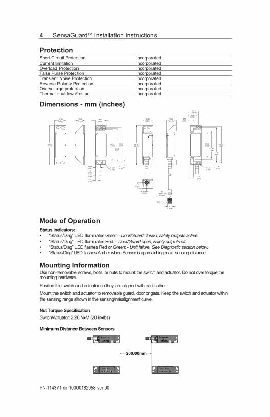
Protection
Short-Circuit Protection Incorporated
Current limitation Incorporated
Overload Protection Incorporated
False Pulse Protection Incorporated
Transient Noise Protection Incorporated
Reverse Polarity Protection Incorporated
Overvoltage protection Incorporated
Thermal shutdown/restart Incorporated
Dimensions - mm (inches)
Mode of Operation
Status indicators:
• “Status/Diag” LED illuminates Green - Door/Guard closed, safety outputs active.• “Status/Diag” LED illuminates Red: - Door/Guard open, safety outputs off.• “Status/Diag” LED flashes Red or Green: - Unit failure. See Diagnostic section below.• “Status/Diag” LED flashes Amber when Sensor is approaching max. sensing distance.
Mounting Information
Use non-removable screws, bolts, or nuts to mount the switch and actuator. Do not over torque the
mounting hardware.
Position the switch and actuator so they are aligned with each other.
Mount the switch and actuator to removable guard, door or gate. Keep the switch and actuator within
the sensing range shown in the sensing/misalignment curve.
Nut Torque Specification
Switch/Actuator: 2.26 N•M (20 in•lbs)
Minimum Distance Between Sensors
PN-114371 dir 10000182958 ver 00
4 SensaGuard
TM
Installation Instructions
24.99
(0.984)
88.14
(3.47)
10.66
(0.42)
7.11
(0.28)
6.78
(0.267)
4.57
(0.18)
¯ 5.08
(¯ 0.2))
4.57
(0.18)
68.31
(2.689)
18.54
(0.73)
72.9
(2.87)
77.98
(3.07)
20.65
(0.813)
24.99
(0.984)
88.14
(3.47)
20.65
(0.813)
4.57
(0.18)
18.54
(0.73)
10.67
(0.42)
13.41
(0.528)
9.96
(0.392)
QD
CONNECTOR
VERSION
M12 x 1
¯ 9.7
(¯ 0.38)
4.57
(0.18)
¯ 5.08
(¯ 0.2)
4.57
(0.18)
77.98
(3.07)
62.53
(2.462)
57.96
(2.282)
82.55
(3.25)
200.00mm
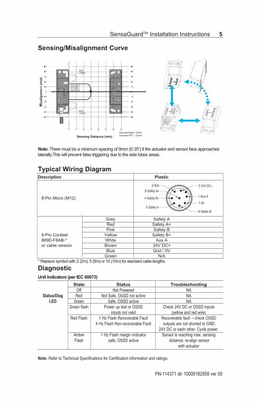
Sensing/Misalignment Curve
Typical Wiring Diagram
Description Plastic
8-Pin Micro (M12)
Grey Safety A
Red Safety A+
Pink Safety B
8-Pin Cordset Yellow Safety B+
889D-F8AB-* White Aux A
or cable version Brown 24V DC+
Blue Gnd / 0V
Green N/A
* Replace symbol with 2 (2m), 5 (5m) or 10 (10m) for standard cable lengths.
Diagnostic
Unit Indicators (per IEC 60073)
State Status Troubleshooting
Off Not Powered NA
Status/Diag Red Not Safe, OSSD not active NA
LED Green Safe, OSSD active NA
Green flash Power up test or OSSD Check 24V DC or OSSD inputs
inputs not valid (yellow and red wire)
Red Flash 1 Hz Flash Recoverable Fault Recoverable fault —check OSSD
4 Hz Flash Non-recoverable Fault outputs are not shorted to GND,
24V DC or each other. Cycle power.
Amber 1 Hz Flash margin indicator Sensor is reaching max. sensing
Flash safe, OSSD active distance; re-align sensor
with actuator
PN-114371 dir 10000182958 ver 00
SensaGuard
TM
Installation Instructions 5
2-24V DC+
1-Aux A
7-0V
6-Safety B
3-N/A
8-Safety A+
4-Safety B+
5-Safety A
Note: Refer to Technical Specifications for Certification information and ratings.
0 5
10
15
20
25
30
35
Assured Make: 15mm
Assured OFF : 27mm
SIDE
LOBES
SIDE
LOBES
ASSURED
SENSING
DISTANCE
Sensing Distance (mm)
Note: There must be a minimum spacing of 9mm (0.35”) if the actuator and sensor face approaches
laterally.This will prevent false triggering due to the side lobes areas.
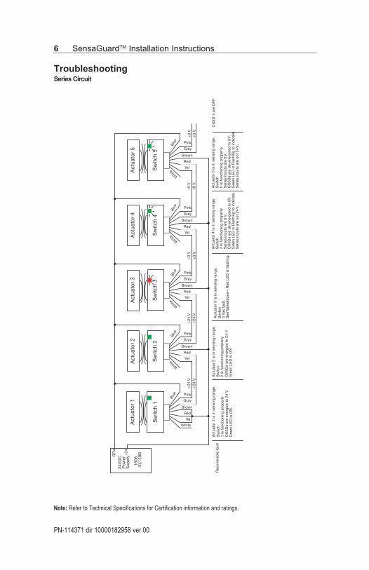
Troubleshooting
Series Circuit
PN-114371 dir 10000182958 ver 00
6 SensaGuard
TM
Installation Instructions
Yel
Red
Brown
Gray
Pink
Blu
e
24V
DC
Pow
erS
upp
ly
1606
-XL1
20D
Sw
itch
1
+24
RTN
Sw
itch
2
White
Whit
eYel
Red
Brown
Gray
Pink
Blu
e
Act
uato
r 1
Act
uato
r 2
Sw
itch
3
Whit
eYel
Red
Brown
Gray
Pink
Blu
e
Act
uato
r 3
Sw
itch
4
Whit
eYel
Red
Brown
Gray
Pink
Blu
e
Act
uato
r 4
Sw
itch
5
Whit
eYel
Red
Brown
Gray
Pink
Blu
e
Act
uato
r 5
+24
V+
24 V
+24
V+
24 V
+0
V+
0 V
+0
V+
0 V
+0
V+
0 V
Act
uato
r 2
is in
sen
sing
ran
ge.
Sw
itch
2 is
func
tioni
ng p
rop
erly
OS
SD
s ar
e en
ergi
ze t
o 24
VG
reen
LE
D is
ON
.
Act
uato
r 3
is in
sen
sing
ran
ge.
Sw
itch
3 ha
s fa
ult.
See
Tab
le A
bov
e—R
ed L
ED
is fl
ashi
ng
Act
uato
r 1
is in
sen
sing
ran
ge.
Sw
itch
1 is
func
tioni
ng p
rop
erly
OS
SD
s ar
e en
ergi
ze t
o 24
VG
reen
LE
D is
ON
.
Act
uato
r 4
is in
sen
sing
ran
ge.
Sw
itch
4 is
func
tioni
ng p
rop
erly
.S
erie
s in
put
s ar
e 0
V.
OS
SD
s ar
e d
e-en
ergi
zed
to
0V.
Gre
en L
ED
is F
lash
ing
to in
dic
ate
Ser
ies
inp
uts
are
not
24V.
Act
uato
r 5
is in
sen
sing
ran
ge.
Sw
itch
5 is
func
tioni
ng p
rop
erly
.S
erie
s in
put
s ar
e 0
V.
OS
SD
s ar
e d
e-en
ergi
zed
to
0V
.G
reen
LE
D is
Fla
shin
g to
ind
icat
eS
erie
s in
put
s ar
e no
t 24
V.
OS
SD
’s a
re O
FFR
ecov
erab
le fa
ult
Note: Refer to Technical Specifications for Certification information and ratings.
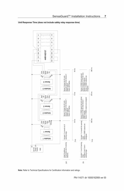
Unit Response Time (does not include safety relay response time)
PN-114371 dir 10000182958 ver 00
SensaGuard
TM
Installation Instructions 7
Note: Refer to Technical Specifications for Certification information and ratings.
Yel
Red
Whi
teG
ray
Pink
Blue
24V
DCPo
wer
Supp
ly
1606
Sensor 1
+24
RT
Sensor 2
Brow
n
Brown
Gra
yPi
nkW
hite
Yel
Red
Blue
Sensor 3
Brown
Yel
Red
Whi
teG
ray
Pink
Blue
A1 S21
S11
4133
2313
S12
S52
4234
2414
A2S3
4S2
2
440R
-N23
127
Actuator 1
Actuator 2
Actuator 3
Initi
al C
ondi
tions
:Al
l act
uato
rs a
re in
sen
sing
dist
ance
.
Actu
ator
1 is
mov
ed o
ut o
fse
nsin
g ra
nge.
Sens
or 2
dro
ps th
e 24
vol
ts
(red
and
yello
w) f
rom
Sen
sor 1
O
SSD
outp
uts.
Gre
en L
ED fl
ashe
s.
Sens
or 3
dro
ps th
e 24
vol
ts
(red
and
yello
w) f
rom
Sen
sor 2
O
SSD
outp
uts.
Gre
en L
ED fl
ashe
s.
0 m
s54
ms
72 m
s90
ms
Actu
ator
1 is
out
of s
ensin
g ra
nge.
Actu
ator
2 a
nd 3
are
in
sens
ing
rang
e.
Actu
ator
1 is
mov
ed in
to s
ensin
g ra
nge.
Sens
or 1
OSS
D ou
tput
s ar
e en
ergi
zed.
Sens
or 2
OSS
D in
puts
(red
and
yel
low
) tra
nsiti
on to
24V
DC
from
Sen
sor 1
O
SSD
outp
uts.
Sens
or 2
OSS
D ou
tput
s ar
e en
ergi
zed
Sens
or 3
OSS
D in
puts
(red
and
ye
llow
) tra
nsiti
on to
24V
DC
from
Se
nsor
2 O
SSD
outp
uts.
Sens
or 3
OSS
D ou
tput
s ar
e en
ergi
zed.
0 m
s36
0 m
s37
8 m
s39
6 m
s
OFF ON
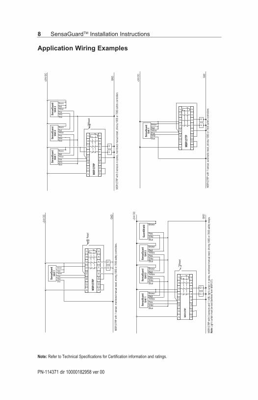
Application Wiring Examples
PN-114371 dir 10000182958 ver 00
8 SensaGuard
TM
Installation Instructions
K1
+24V
DC
MSR
127R
P w
ith 1
sen
sor,
mon
itore
d m
anua
l res
et, d
rivin
g 10
0S o
r 700
S sa
fety
con
trolle
rs.
A1S1
1S5
2S1
213
2333
41
S21
S22
S34
A214
2434
42
MSR
127R
P
Rese
t
GND
BlueGrayPink
YellowRed
Brown
Sens
aGua
rdUn
it 1
K2
+24V
DC
GND
MSR
127R
P w
ith 3
sen
sors
in s
erie
s, m
onito
red
man
ual r
eset
, driv
ing
100S
or 7
00S
safe
ty c
ontro
llers
BlueGrayPinkYellowRed
Brown
Sens
aGua
rdUn
it 1
Sens
aGua
rdUn
it 2
Sens
aGua
rdUn
it 3
K1
A1S1
1S5
2S1
213
2333
41
S21
S22
S34
A214
2434
42
MSR
127R
P
Rese
t
K2
BlueGrayPinkYellowRed
Brown
BlueGrayPink
YellowRedBrown
MSR
127R
P w
ith 3
sen
sors
and
1 4
40L
light
cur
tain
in s
erie
s, m
onito
red
man
ual r
eset
, driv
ing
100S
or 7
00S
safe
ty re
lays
.No
te: L
ight
cur
tain
mus
t be
last
(far
thes
t fro
m M
SR12
7).
GND
A1S1
1S5
2S1
213
2333
41
S21
S22
S34
A214
2434
42
MSR
127R
P
Rese
t
K1K2
+24V
DC
BlueGrayPinkYellowRedBrown
Sens
aGua
rdUn
it 1
Sens
aGua
rdUn
it 2
Sens
aGua
rdUn
it 3
Gua
rdSh
ield
BlueGrayPinkYellowRedBrown
BlueGrayPinkYellowRedBrown
BlueGrayPink
Brown
A1S1
1S5
2S1
213
2333
41
S21
S22
S34
A214
2434
42
MSR
127T
P
GND
MSR
127R
P w
ith 1
sen
sor,
auto
mat
ic re
set,
drivi
ng 1
00S
or 7
00S
safe
ty c
ontro
llers
+24V
DC
Sens
aGua
rdUn
it 1
K1K2
BlueGrayPinkYellowRedBrown
Note: Refer to Technical Specifications for Certification information and ratings.
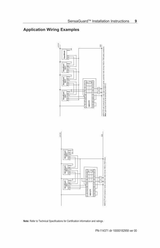
Application Wiring Examples
PN-114371 dir 10000182958 ver 00
SensaGuard
TM
Installation Instructions 9
Note: Refer to Technical Specifications for Certification information and ratings.
MSR
127T
P w
ith 3
sen
sors
in s
erie
s, a
utom
atic
rese
t, dr
iving
100
S or
700
S re
lays
.
MSR
127T
P
+24V
DC
GND
Blue
GrayPink
YellowRed
Brown
Sens
aGua
rdUn
it 1
K1
A1S1
1S5
2S1
213
2333
41
S21
S22
S34
A214
2434
42
K2
Blue
GrayPink
YellowRed
Brown
Blue
GrayPink
YellowRed
Brown
Sens
aGua
rdUn
it 3
Sens
aGua
rdUn
it 2
MSR
127T
P w
ith 3
sen
sors
and
1 4
40L
light
cur
tain
in s
erie
s, a
utom
atic
rese
t, dr
iving
100
S or
700
S sa
fety
con
tact
ors.
Note
: Lig
ht c
urta
in m
ust b
e la
st (f
arth
est f
rom
MSR
127)
MSR
127T
P
GND
A1S1
1S5
2S1
213
2333
41
S21
S22
S34
A214
2434
42
K1K2
+24V
DC
Blue
GrayPink
YellowRed
Brown
Blue
GrayPink
YellowRed
Brown
Blue
GrayPink
YellowRed
Brown
Blue
GrayPink
Brown
Gua
rdSh
ield
Sens
aGua
rdUn
it 1
Sens
aGua
rdUn
it 3
Sens
aGua
rdUn
it 2
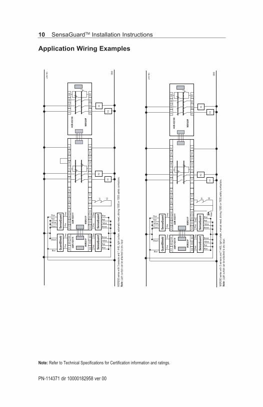
Application Wiring Examples
PN-114371 dir 10000182958 ver 00
10 SensaGuard
TM
Installation Instructions
MSR
200
serie
s w
ith 3
sen
sors
and
1 4
40L
light
cur
tain
, aut
omat
ic re
set,
drivi
ng 1
00S
or 7
00S
safe
ty c
onta
ctor
s.No
te: L
i ght
cur
tain
can
be
atta
ched
to a
ny in
put
Gua
rdSh
ield
+24V
DC
GND
440R
-H23
177
Y40
Y41
S51
S12
S20
S32
S11
S21
S31
S41
1323
31Y4
2A1
S32
S20
S12
S42
S50
S62
S34
Y1Y2
Y314
2432
Y32
Y33
Y30
A2S6
2S5
0S4
2440R
-H23
179
K1
S32
S20
S12
S62
S50
S42
S32
S32
440R
-H23
180
MSR
221P
MSR
211P
MSR
230P
K2K1 K2
K3
K4
Sens
aGua
rd
Blue
Brown
Gra
yPi
nk
Blue
Brown
Yellow
Red
Gra
yPi
nk
Sens
aGua
rdSe
nsaG
uard
Gra
yPi
nkG
ray
Pink
Blue
Brown
Yellow
Red
Blue
Brown
Yellow
RedM
SR20
0 se
ries
with
3 s
enso
rs a
nd 1
440
L lig
ht c
urta
in, m
anua
l res
et, d
rivin
g 10
0S o
r 700
S sa
fety
con
tact
ors.
Note
: Lig
ht c
urta
in c
an b
e at
tach
ed to
any
inpu
t.
Rese
t
Gua
rdSh
ield
+24V
DC
GND
440R
-H23
177
Y40
Y41
S51
S12
S20
S32
S11
S21
S31
S41
1323
31Y4
2A1
S32
S20
S12
S42
S50
S62
S34
Y1Y2
Y314
2432
Y32
Y33
Y30
A2S6
2S5
0S4
2440R
-H23
179
K1
S32
S20
S12
S62
S50
S42
S32
S32
440R
-H23
180
MSR
221P
MSR
211P
MSR
230P
K2K1 K2
K3
K4
Sens
aGua
rd
Blue
Brown
Gra
yPi
nk
Blue
Brown
Yellow
Red
Gra
yPi
nk
Sens
aGua
rdSe
nsaG
uard
Gra
yPi
nkG
ray
Pink
Blue
Brown
Yellow
Red
Blue
Brown
Yellow
Red
Note: Refer to Technical Specifications for Certification information and ratings.
PN-114371 dir 10000182958 ver 00
SensaGuard
TM
Installation Instructions 11
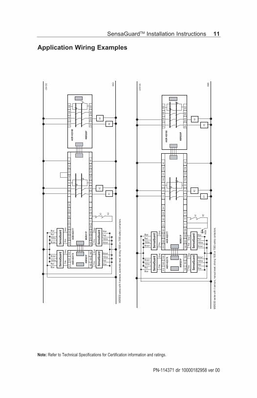
Note: Refer to Technical Specifications for Certification information and ratings.
MSR
200
serie
s w
ith 4
sen
sors
, aut
omat
ic re
set,
drivi
ng 1
00S
or 7
00S
safe
ty c
onta
ctor
s.
Yellow
Red
+24V
DC
GND
440R
-H23
177
Y40
Y41
S51
S12
S20
S32
S11
S21
S31
S41
1323
31Y4
2A1
S32
S20
S12
S42
S50
S62
S34
Y1Y2
Y314
2432
Y32
Y33
Y30
A2S6
2S5
0S4
2440R
-H23
179
K1
S32
S20
S12
S62
S50
S42
S32
S32
440R
-H23
180
MSR
221P
MSR
211P
MSR
230P
K2K1 K2
K3
K4
Sens
aGua
rdSe
nsaG
uard
Blue
Brown
Gra
yPi
nk
Blue
Brown
Yellow
Red
Gra
yPi
nk
Sens
aGua
rdSe
nsaG
uard
Gra
yPi
nkG
ray
Pink
Blue
Brown
Yellow
Red
Blue
Brown
Yellow
Red
MSR
200
serie
s w
ith 4
sen
sors
, man
ual r
eset
, driv
ing
100S
or 7
00S
safe
ty c
onta
ctor
s.
Rese
t
+24V
DC
GND
440R
-H23
177
Y40
Y41
S51
S12
S20
S32
S11
S21
S31
S41
1323
31Y4
2A1
S32
S20
S12
S42
S50
S62
S34
Y1Y2
Y314
2432
Y32
Y33
Y30
A2S6
2S5
0S4
2440R
-H23
179
K1
S32
S20
S12
S62
S50
S42
S32
S32
440R
-H23
180
MSR
221P
MSR
211P
MSR
230P
K2K1 K2
K3
K4
Sens
aGua
rdSe
nsaG
uard
Blue
Brown
Gra
yPi
nk
Blue
Brown
Yellow
Red
Yellow
Red
Gra
yPi
nk
Sens
aGua
rdSe
nsaG
uard
Gra
yPi
nkG
ray
Pink
Blue
Brown
Yellow
Red
Blue
Brown
Yellow
Red
Application Wiring Examples
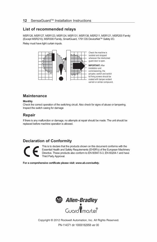
List of recommended relays
MSR126, MSR127, MSR123, MSR124, MSR131, MSR138, MSR211, MSR121, MSR200 Family
(Except MSR210), MSR300 Family, SmartGuard, 1791 DS DeviceNet™ Safety I/O.
Relay must have light curtain inputs.
Maintenance
Monthly
Check the correct operation of the switching circuit. Also check for signs of abuse or tampering.
Inspect the switch casing for damage
Repair
If there is any malfunction or damage, no attempts at repair should be made. The unit should be
replaced before machine operation is allowed.
Declaration of Conformity
This is to declare that the products shown on this document conforms with the
Essential Health and Safety Requirements (EHSR’s) of the European Machinery
Directive. These products also conform to EN 60947-5-3, EN 60204-1 and have
Third Party Approval.
For a comprehensive certificate please visit: www.ab.com/safety.
PN-114371 dir 10000182958 ver 00
12 SensaGuard
TM
Installation Instructions
Check the machine is isolated and stopped whenever the interlocked guard door is open.
IMPORTANT: Afterinstallation and commissioning, the actuator, switch and switch lid fixing screws should be coated with tamper evident varnish or similar compound.
R
Copyright © 2012 Rockwell Automation, Inc. All Rights Reserved.