INSTALLATION MANUAL - Baja Kits
16
www.bajakits.com Vehicle: 2015+ Chevy Colorado, 2WD and 4WD Prerunner Kit Part # CC0P15 INSTALLATION MANUAL **NOTE: Read through entire installation manual before deciding whether to attempt the procedure. Do not attempt if you do not possess the proper know-how and tools necessary to complete the installation. Professional installation is highly recommended. Level 2 Install: Bolt on w/drilling and/or minimal grinding Install Time: 8 hours (approximate)
Transcript of INSTALLATION MANUAL - Baja Kits

www.bajakits.com
Vehicle: 2015+ Chevy Colorado, 2WD and 4WD Prerunner Kit
Part # CC0P15
INSTALLATION MANUAL
**NOTE: Read through entire installation manual before deciding whether to attempt the
procedure. Do not attempt if you do not possess the proper know-how and tools
necessary to complete the installation. Professional installation is highly recommended.
Level 2 Install: Bolt on w/drilling and/or minimal grinding
Install Time: 8 hours (approximate)

Prerunner Kit
www.bajakits.com 1
Vehicle: 2015+ Chevy Colorado, 2WD and 4WD Tool List:
- 13/16” Socket/wrench
- 15/16” Socket/wrench
- 3/4” Socket/wrench
- 10mm Socket/wrench
- 1/2” – 12 point socket
- 9/16” – 12 point socket
- Red threadlocker
Parts List:
- LH & RH Upper Control Arm (UCA)
- Uniball (installed)
- Delrin Bushings (installed)
- Crush sleeves (installed)
- Baja Kits badges (installed)
- Zerk fittings (installed)
- Misalignment spacers (installed)
- LH & RH Lower Control Arm (LCA)
- Uniball (installed)
- Delrin bushings (installed)
- Crush sleeves (installed)
- Baja Kits badges (installed)
- Zerk fittings (installed)
- Misalignment spacers (installed)
- Steering extensions
- Extended length axle (4WD only)
- Extended length brake lines with hardware
- King Coilovers with hardware (if purchased)
- King Bypass shocks with hardware (if purchased)
- RH and LH Bypass Mounts (if purchased

Prerunner Kit
www.bajakits.com 2
LOWER CONTROL ARM ASSEMBLY COMPONENTS

Prerunner Kit
www.bajakits.com 3
UPPER CONTROL ARM ASSEMBLY COMPONENTS

Prerunner Kit
www.bajakits.com 4
BYPASS MOUNT ASSEMBLY COMPONENTS (IF PURCHASED)

Prerunner Kit
1. Start by lifting the front end of the vehicle and placing wheel chocks behind both rear wheels.
2. Remove the stock brake lines and sway bar.
3. Remove the UCAs on both sides.
4. Remove the shocks.
5. Remove the LCAs on both sides.
6. Remove the axles on both sides (4WD only).
7. Remove inner plastic fenderwell lining.
www.bajakits.com 5

Prerunner Kit
www.bajakits.com 6
Cut off OEM droop stop.
8. Cut off stock droop stop in order to gain the maximum amount of suspension travel (see photo below).

Prerunner Kit
9. Install Baja Kits LCA to the frame on both sides of the vehicle using the stock alignment cams.
- Torque to 180 ft-lbs.
10. Rebuild stock Colorado axles using the extended length center portion provided (4WD only).
- Instruction guide for this procedure (BajaKits “Axle Rebuild Manual”) can be found in the package or on
our webpage.
- If you do not have the correct tools or expertise, please have the axles rebuilt by a professional.
11. Install stock spindle onto the Baja Kits LCA.
www.bajakits.com 7
Prerunner Kit
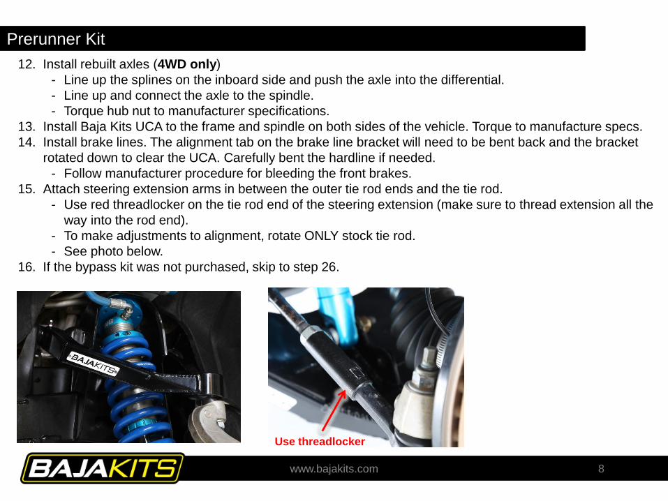
12. Install rebuilt axles (4WD only)
- Line up the splines on the inboard side and push the axle into the differential.
- Line up and connect the axle to the spindle.
- Torque hub nut to manufacturer specifications.
13. Install Baja Kits UCA to the frame and spindle on both sides of the vehicle. Torque to manufacture specs.
14. Install brake lines. The alignment tab on the brake line bracket will need to be bent back and the bracket
rotated down to clear the UCA. Carefully bent the hardline if needed.
- Follow manufacturer procedure for bleeding the front brakes.
15. Attach steering extension arms in between the outer tie rod ends and the tie rod.
- Use red threadlocker on the tie rod end of the steering extension (make sure to thread extension all the
way into the rod end).
- To make adjustments to alignment, rotate ONLY stock tie rod.
- See photo below.
16. If the bypass kit was not purchased, skip to step 26.
www.bajakits.com 8
Use threadlocker

Prerunner Kit 17. Remove the aluminum shield that is over the UCA back pivot pocket and discard.
18. Cut slots in the sheetmetal fenderwell firewall lip that hangs down and bend it back. See middle
photo below.
- This is for tire clearance at full bump.
19. Cut the inner sheetmetal fenderwell for the bypass mount. See photo on the right.
- There is plumbing and harnesses behind the fenderwell so be sure to not hit them.
www.bajakits.com 9
Aluminum Shield
Cut and bend lip back
Cut out for bypass mount

Prerunner Kit 20. On the driver side, push the plumbing hose and wiring harness up and zip tie out of the way. See left photo.
21. Sand off the paint on top of the OEM shock box and where the bypass mount sits on the frame.
22. Remove the coil from the coilover shock and bolt to the LCA outer shock pocket.
- Coil is removed to be able to cycle the suspension fully to ensure clearance.
- The resi fitting should be facing the rear of the vehicle. Big spacer on lower eyelet should be facing the rear
as well.
23. Install the bypass mount to the shock box with the supplied hardware.
- Before welding to the frame, be sure the fenderwell was trimmed enough to clear everything.
- On the driver side, the brake hardline goes between the opening on the bypass mount. See middle photo.
24. Disconnect battery and weld bypass to the frame and shock box. It is recommended to weld as much as possible.
See photo in the middle for recommended areas.
25. Locate supplied bypass resi mount tabs onto bypass mount and weld on. See photo on the right.
www.bajakits.com 10
Hardline location
Weld
Weld
WeldBypass res mounts

Prerunner Kit 26. Remove the three bolts on top of the shock and install the supplied shock resi mount. See photo for
orientation. Note the bent plate is welded offset. Reinstall three upper shock bolts.
27. Cover surroundings and paint the bypass mount to prevent rusting.
28. Install bypass shock to LCA and bypass mount. Use hose clamps to mount the bypass resi to the bypass
mount.
29. Install tires and cycle the suspension to check for any interferences. Trim any additional areas as needed.
www.bajakits.com 11
Bypass mount side
Top

Prerunner Kit
30. After trimming, remove shock and reinstall coil.
31. Install shock back on the truck. If using the Baja Kits custom King Shocks, Use the outer shock pocket on the
LCA. Otherwise the OEM or King OEM Replacement, use the inner pocket. The longer spacer on the lower shock
eyelet faces the rear of vehicle. Use 3/8-16 hardware with threadlocker when mounting the bypass mount to the
shock plate.
- If bypass kit purchased, only use Baja Kits Custom shock. WILL NOT WORK WITH OEM REPLACEMENT
SHOCK.
32. Using hose clamps, install the coilover resi to the resi mount. Route as shown in photo.
- The OEM King replacement shocks have the resi line going toward the front of the truck.
- If hose rubs on anything, add rubber insulation around hose to protect from wearing.
www.bajakits.com 12
Longer spacerPassenger side shown (custom Kings)
Driver side shown (OEM Kings)

Prerunner Kit
33. Grease all control arm pivots via grease zerks. They come with very little grease from our factory for
installation purposes only. Failure to grease will result in premature failure.
34. Double check all hardware is tight.
35. Install tires and torque lug nuts to 140 ft-lbs.
36. Take to a tire shop or dealership to have the alignment done. Failure to do so will result in poorly worn
tires.
37. After the first 500 miles, check that all pivot bolts (shock and control arms) are tight.
www.bajakits.com 13
Prerunner Kit W/ Bypass Prerunner Kit

Prerunner Kit
38. Make sure to follow the BajaKits “General Maintenance Manual” for the life of the kit to ensure longevity of
the suspension components.
www.bajakits.com 14

Prerunner Kit
FOR ANY TECHNICAL QUESTIONS OR
SUPPORT, PLEASE CONTACT BAJA KITS
AT 949-566-8615
www.bajakits.com 15
Rev Description Date Initial
- Initial Release 8/10/2017 JOS
A Added Step 7 8/21/2017 TB
B Bypass Notes 9/15/2017 TB