Installation Instructions - utcccs-cdn.com · The accessory kit is intended for installation at the...
8
Manufacturer reserves the right to discontinue, or change at any time, specifications or designs without notice and without incurring obligations. Catalog No. 04-53300046-01 Printed in U.S.A. Form 30XW-5SI Pg 1 11-09 Replaces: New Installation Instructions Part No. 00EFN900004300A, 00EFN900004500A, 00EFN900004600A SAFETY CONSIDERATIONS Installing, starting up, and servicing air-conditioning equip- ment can be hazardous due to system pressures, electrical components, and equipment location. Only trained, qualified installers and service mechanics should install, start up, and service this equipment. When working on the equipment, observe precautions in the literature and on tags, stickers, and labels attached to the equipment. Fol- low all safety codes. Wear safety glasses and work gloves. INTRODUCTION The spring isolation accessory kits consist of 4 cast iron spring-flex mounting isolators. The isolator top and bottom surfaces have oil resistant elastomeric pads attached. The 30XW condensers each have two mounting channels that are 10 in. wide and up to 47 3 / 8 in. long. One isolator is to be mounted under each channel end through the 7 / 8 in. clearance hole located at the outer edge of the channel. These isolators are NOT intended for seismic duty, but are intended to reduce the vibration and noise levels transmitted from the chiller to the surrounding environment where the unit is installed. INSTALLATION Install the accessory kit as follows: 1. The accessory kit is intended for installation at the ini- tial unit installation. One accessory kit is required per chiller. The contents of the kit and part number required are shown in Table 1. All mounting hardware is field supplied. 2. The chiller mounting pad/rail surface must be level. The base plates of the isolators must be no more than 1 /4 in. different in elevation for proper operation. The entire isolator base plate area must be resting on a flat surface properly designed for the chiller being installed. 3. Isolators are provided with 5 / 8 in. wide slots on each end for bolt mounting to the floor, pad, and/or rails as required. Mounting hardware is field supplied. See Fig. 1 for isolator dimensions. 4. Position isolators according to the condenser channel information in Fig. 2-3C. 5. Remove leveling bolt and lockdown nut from top of each isolator and save for use later. Install the 30XW chiller onto the top plates of the four isolators, making sure the channel mounting holes in the chiller are cen- tered over the isolator leveling bolt holes. Reinstall the isolator top bolts and lockdown nuts using a field- supplied 3 /4 in. washer between the lockdown nut and chiller mounting channel. Leave lockdown nut loose. 6. All isolators require adjustment so that a 1 / 4 to 1 / 2 in. gap is set between the upper and lower mount hous- ings. Use leveling bolt to achieve the gap. Adjust isola- tor bolts in sequence: screw down one complete turn on the bolt of each mounting. Repeat with remaining 3 isolator bolts using the same sequence until the proper gap is obtained on all isolators. See Fig. 1. 7. With proper gap obtained on all four isolators, tighten lockdown nut on each isolator to secure the chiller to the isolators. Table 1 — Package Contents ACCESSORY PART NUMBER ISOLATOR PART NUMBER ISOLATOR COLOR CODE CHILLER MOUNTING LOCATIONS (SEE FIG. 4) ISOLATOR QTY 00EFN900004300A (30XW325-400) C4E-1D-4800 C4E-1D-3600 Gray Dark Green 1, 2 3, 4 2 2 00EFN900004500A (30XW150-200) C4E-1D-2040 C4E-1D-2700 Black Purple 1, 2, 3 4 3 1 00EFN900004600A (30XW250-300) C4E-1D-2040 C4E-1D-2700 C4E-1D-3600 Black Purple Dark Green 1 2, 3 4 1 2 1 30XW150-400 Spring Isolation Kit Accessory
Transcript of Installation Instructions - utcccs-cdn.com · The accessory kit is intended for installation at the...

Manufacturer reserves the right to discontinue, or change at any time, specifications or designs without notice and without incurring obligations.Catalog No. 04-53300046-01 Printed in U.S.A. Form 30XW-5SI Pg 1 11-09 Replaces: New
Installation InstructionsPart No. 00EFN900004300A, 00EFN900004500A,
00EFN900004600A
SAFETY CONSIDERATIONSInstalling, starting up, and servicing air-conditioning equip-
ment can be hazardous due to system pressures, electricalcomponents, and equipment location.
Only trained, qualified installers and service mechanicsshould install, start up, and service this equipment. Whenworking on the equipment, observe precautions in the literatureand on tags, stickers, and labels attached to the equipment. Fol-low all safety codes. Wear safety glasses and work gloves.
INTRODUCTION
The spring isolation accessory kits consist of 4 cast ironspring-flex mounting isolators. The isolator top and bottomsurfaces have oil resistant elastomeric pads attached. The30XW condensers each have two mounting channels that are10 in. wide and up to 473/8 in. long. One isolator is to bemounted under each channel end through the 7/8 in. clearancehole located at the outer edge of the channel. These isolatorsare NOT intended for seismic duty, but are intended to reducethe vibration and noise levels transmitted from the chiller to thesurrounding environment where the unit is installed.
INSTALLATION
Install the accessory kit as follows:
1. The accessory kit is intended for installation at the ini-tial unit installation. One accessory kit is required perchiller. The contents of the kit and part numberrequired are shown in Table 1. All mounting hardwareis field supplied.
2. The chiller mounting pad/rail surface must be level.The base plates of the isolators must be no more than1/4 in. different in elevation for proper operation. Theentire isolator base plate area must be resting on a flatsurface properly designed for the chiller beinginstalled.
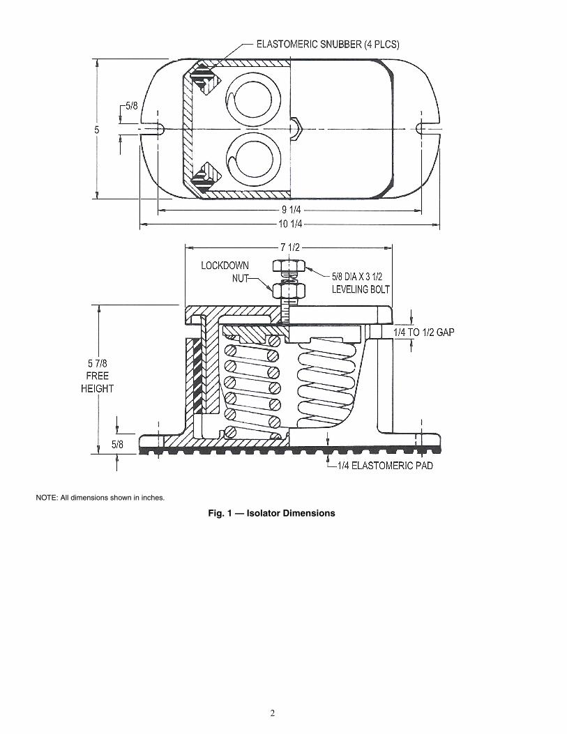
3. Isolators are provided with 5/8 in. wide slots on eachend for bolt mounting to the floor, pad, and/or rails asrequired. Mounting hardware is field supplied. SeeFig. 1 for isolator dimensions.
4. Position isolators according to the condenser channelinformation in Fig. 2-3C.
5. Remove leveling bolt and lockdown nut from top ofeach isolator and save for use later. Install the 30XWchiller onto the top plates of the four isolators, makingsure the channel mounting holes in the chiller are cen-tered over the isolator leveling bolt holes. Reinstall theisolator top bolts and lockdown nuts using a field-supplied 3/4 in. washer between the lockdown nut andchiller mounting channel. Leave lockdown nut loose.
6. All isolators require adjustment so that a 1/4 to 1/2 in.gap is set between the upper and lower mount hous-ings. Use leveling bolt to achieve the gap. Adjust isola-tor bolts in sequence: screw down one complete turnon the bolt of each mounting. Repeat with remaining3 isolator bolts using the same sequence until theproper gap is obtained on all isolators. See Fig. 1.
7. With proper gap obtained on all four isolators, tightenlockdown nut on each isolator to secure the chiller tothe isolators.
Table 1 — Package Contents
ACCESSORY PART NUMBER ISOLATORPART NUMBER
ISOLATORCOLOR CODE
CHILLER MOUNTING LOCATIONS(SEE FIG. 4)
ISOLATOR QTY
00EFN900004300A(30XW325-400)
C4E-1D-4800C4E-1D-3600
GrayDark Green
1, 23, 4
22
00EFN900004500A(30XW150-200)
C4E-1D-2040C4E-1D-2700
BlackPurple
1, 2, 34
31
00EFN900004600A(30XW250-300)
C4E-1D-2040C4E-1D-2700C4E-1D-3600
BlackPurple
Dark Green
12, 3
4
121
30XW150-400Spring Isolation Kit Accessory
2
Fig. 1 — Isolator Dimensions
NOTE: All dimensions shown in inches.
a30-4931.tif

3
CHANNEL CENTER AND LENGTH DIMENSIONS (in.)
Fig. 2 — Condenser Channel Dimensions
30XW UNIT SIZE A B C D150-200 56.39 42.90 37.02 2.94250-300 56.39 47.38 39.50 3.94325-400 56.39 47.38 39.50 3.94
PLAN VIEW
UNIT CONTROL BOX
SUPPORTCHANNELLENGTH
B
10 IN. TYP
A
C
D
CONDENSERCHANNELMOUNTINGHOLES (4)
a30-4932

4
Fig. 3A — Chiller Mounting Locations — 30XW150-200
LEGENDMLV — Minimum Load ValveSAE — Society of Automotive EngineersSSV — Suction Service Valve
a30-5060

5
Fig. 3B — Chiller Mounting Locations — 30XW250-300
LEGENDMLV — Minimum Load ValveSAE — Society of Automotive EngineersSSV — Suction Service Valve
a30-5062

6
Fig. 3C — Chiller Mounting Locations — 30XW325-400
LEGENDMLV — Minimum Load ValveSAE — Society of Automotive EngineersSSV — Suction Service Valve
a30-5061

7
Fig. 4 — Isolation Spring Mounting Location
NOTES:1. See Table 1 for isolation spring color and mounting location.2. The recommended service clearance around the machine is 3 ft [914 mm].
Consult local electrical codes for minimum clearance requirements on con-trol panel side.
30XW150-300
30XW325-400
a30-4935
a30-4894

Manufacturer reserves the right to discontinue, or change at any time, specifications or designs without notice and without incurring obligations.Catalog No. 04-53300046-01 Printed in U.S.A. Form 30XW-5SI Pg 8 2-10A 11-09 Replaces: New
Copyright 2009 Carrier Corporation