Installation Instructions the excavation must be ... advantageous to lay out the inlet and outlet...
19
Installation Instructions Triton Stormwater Solutions Chamber System for Stormwater Management Revised June/2015. Supersedes all previous installation manuals.
Transcript of Installation Instructions the excavation must be ... advantageous to lay out the inlet and outlet...

Installation InstructionsTriton Stormwater Solutions Chamber System for Stormwater Management
Revised June/2015. Supersedes all previous installation manuals.

Call Triton SWS at 810.222.7652 for technical and product information or visit www.tritonsws.com1
Triton Stormwater Solutions Chamber System for Stormwater Management Installation Manual
SINGLE LAYER SYSTEM
DOUBLE STACKED SYSTEM
Section drawing can be downloaded at www.tritonsws.com/support_center/downloads
This installation guide provides the requirements for proper installation of the Triton Stormwater Solutions system. Non-adherence to this guide may result in damage to chambers during installation. Replacement of damaged chambers during or after backfilling is costly and very time consuming. It is recommended that all installers be familiar with this manual, and that the contractor inspects the chambers for distortion, damage and joint integrity as work progresses.

Call Triton SWS at 810.222.7652 for technical and product information or visit www.tritonsws.com 2
Before You BeginREQUIRED MATERIALS AND EQUIPMENT LIST• Acceptable 0.75" – 2" (19.05mm – 50.8mm) washed,
crushed, angular stone per, Tables 2 & 3 on page 9• Acceptable fill materials per Table 3 on page 9• Filter fabric, per Table 1 on page 8• Triton SWS end caps & Triton SWS chambers• Watch the Triton SWS Installation video at:
http://www.tritonsws.com/video#video-double-stack• Reciprocating saw with a tapered bi-metal blade, router,
jig saw or an air saw (to custom, cut end cap, side andtop holes).*Portable air compressor and power source if usingan air saw. A proper diameter hole saw works best.
• PVC distribution pipe, per engineer’s plan for connectingthe Triton SWS system together
• Self-Expanding closed cell foams (e.g., Great Stuff™Pond and Stone insulating foam) to seal all gaps
• OSHA compliance• Stone bucket• Tracked excavator that does not exceed the ground
pressure limits listed in Table 4 on page 13
• Transit or laser• Vibratory roller with maximum gross vehicle weight of
12,000 lbs. (5443.108 kg) and a maximum dynamic forceof 20,000 lbs. (9071.847 kg). Also a walk-behind platecompactor whose compaction force does not exceed2,500 lbs (10kN).
• Installer(s) should wear gloves and proper eye protection,proper clothing and dust mask when cutting
• Review directions on all products to ensure proper installation• 60" (1524mm) forks to unload pallets and rope to pull pal-
lets to back of van.• Fork pallet only. Do not lift stack by placing forks under
product• Remove all packaging, i.e., bands, stretch wrap, labels, and
protective film, from product before installing them• A minimum of a 3" (76mm) wide x 10' (3m) Web Sling with
a choker load rating of 3,760 pounds or more to lowerproduct into trench
Requirements for System Installation 1. Triton Stormwater Solutions LLC requires installing con-
tractors to use and understand Triton SWS’ most cur-rent installation instructions prior to beginning systeminstallation.
All illustrations and photographs are examples of typicalsituations. Actual designs may vary. Be sure to followthe engineer’s drawings.
2. Triton SWS offers installation consultations to installingcontractors. Contact Triton SWS at least 10 days prior tosystem installation to arrange a pre-installation consulta-tion. Our representatives can answer questions, addresscomments and provide information about the Triton SWS’chamber system’s installation requirements. Call 1-810-222-7652 or visit www.tritonsws.com to receive the mostcurrent version of our installation instructions.
3. Contact local underground utility companies orlocating agency at least 3 days prior to construction.
4. All Triton SWS’ system designs must be certified by aregistered professional engineer.
5. Triton SWS’ requirements for systems with a pavementdesign (asphalt, concrete pavers, etc.): Minimum coveris 18" not including pavement; maximum cover is 600"(15,240mm) including pavement design. For installationsthat do not include pavement, where rutting from vehiclesmay occur, minimum required cover is 24" (609.6mm) ,maximum cover is 600" (15,240mm).
6. The contractor must report any discrepancies withthe system subgrade soil’s bearing capacity to thedesign engineer.
7. Check chambers for shipping damage prior to installation.Units that have been damaged must not be installed.Contact Triton SWS immediately upon discovery of anydamage.
8. Filter fabric must be used as indicated in the engineer’sdrawings.
9. To maintain row separation distances and preventchamber displacement, place stone between chamberrows and around perimeter as required by the mostcurrent version of Triton SWS Installation Instructions.
10. Backfilling of the chamber system must be in accordancewith the most current version of Triton SWS’ Installa-tion Instructions, listed on the lower left of the installa-tion manual cover.
11. The contractor must refer to Triton SWS InstallationInstructions for Tables of Acceptable Vehicle Loads atvarious depths of cover. The contractor is responsiblefor preventing vehicles that exceed Triton SWS’ re-quirements from traveling across or parking over thestormwater system. Temporary fencing, warning tapeand appropriately located signs are commonly usedto prevent unauthorized vehicles from enteringsensitive construction areas.
12. The contractor must apply erosion and sediment controlmeasures to protect the stormwater system during allphases of site construction, per local codes and designengineer’s specifications.
13. Remove all packaging, i.e., bands, stretch wrap, labels,and protective film, from product before installing them.

Triton Stormwater Solutions Chamber System for Stormwater Management Installation Manual
Call Triton SWS at 810.222.7652 for technical and product information or visit www.tritonsws.com3
Requirements for Excavating and Preparing the Site1. Excavate and level the designated area. Be sure to
excavate at least one extra foot around the chamberperimeter to allow for proper fit and adequatecompaction. (Bed dimensions are specified onengineer’s plan.)
2. Excavation must be free of standing water. Dewateringmeasures must be taken if required. Positive drainageof the excavation must be maintained.
3. Prepare the chamber bed’s subgrade soil as outlined inthe engineer’s drawings.
4. Line trench walls with any of the acceptable AASHTOM288 class 2 Non-Woven geotextiles listed in table1 on page 8. Overlap adjacent filter fabric by at least2' (.6096m) . Do not place filter fabric under theTriton SWS’ ChambersTM. The filter fabric will clog,restricting the infiltration rate of the field.
In conditions where the sub-soils may migrate upinto the base stone, a geofabric may be necessary.Contact the civil engineer responsible for the projectif you think this may occur during the compaction ofthe stone.
5. Perforated pipe outlet underdrains may be designed withinthe one foot stone perimeter. Install perforated pipe outletunderdrains as required by the engineer’s drawings.
6. Place acceptable 0.75"– 2" (19.05mm – 50.8mm) washed,crushed, angular stone foundation material over theentire bottom surface of the bed (see Tables 2 & 3 forstone requirements). Refer to the engineer’s drawings forsubgrade soil preparation and required stone foundationthickness.
7. Compact the stone using a vibratory roller with its fulldynamic force applied to achieve a flat surface.
Requirements for System Installation 14. Triton SWS’ systems must be installed in accordance
with Triton Stormwater Solutions’ minimum require-ments. Failure to do so will void the limited warranty.
15. Triton SWS’ product warranty is limited. See currentproduct warranty for details on page 14. To acquire acopy call Triton SWS at 1-810-222-7652 or visitwww.tritonsws.com.
16. For installation instructions for any additional structuresor fittings not covered in these instructions, contactTriton SWS at 1-810-222-7652.
17. Supply Triton SWS and its distributor with the vehiclespecifications that will be used during the installation ofthe system 10 business days prior to start of installationfor approval.
18. When light pole bases are located within the footprintof the system, prior to installation of the system, theelectrical contractor must be consulted to ensuresufficient room has been provided for light polebase excavation.
Use a plate compactor to achieve a flat surface. Compaction of the embedment stone is necessary if the angular stone used is of nominal graded size less than 1.5" (40 mm). Compaction of the embedment stone is recommended when doing a double stack system so a flat surface is achieved for the installation of the upper system.

Call Triton SWS at 810.222.7652 for technical and product information or visit www.tritonsws.com 4
Requirements for Assembling Inlet PipesNOTE: Depending on the system’s design, it may be advantageous to lay out the inlet and outlet pipe systems prior to forming the bed of chambers.
1. Temporarily lay out the main header system accordingto the engineer’s drawings.
2. Stone foundation scour control measures such assplash pads, riprap, or geotextiles may be required bythe design engineer. Locate and install scour controlmeasures, per engineer’s drawings, if required.
3. Set first chamber of each row aligned with their inletpipes if applicable or with the Main Header Row.
Per the engineer’s drawings, ensure that the minimum*clear spacing, measured between feet, is maintainedbetween adjacent rows. Separate chambers andinlet fittings as necessary to maintain the minimumseparation distance between chamber rows.
Requirements for Installing the ChambersTo begin building the chamber bed, orient the cham-bers so the end labeled with the build direction arrow is pointed in the direction of the build.
Maintain the minimum separation between chamber rows (measurement taken from the foot of chambers).
4. Pre-drill a hole large enough to use a saw listed on page2 under the “Before you Begin” section. Cut an openingfor the inlet piping in the applicable end caps at the speci-fied invert height.
NOTE: Inlet pipe openings may be cut anywhere onan end cap. To do this, take a short length of pipe anduse a marker to draw an outline of the pipe on the endcap at the correct height or use the proper diameterguides on the face of the end cap to cut required hole.
5. Insert the distribution pipes into the end caps.
6. Once chamber spacing requirements are met, theheader row system may be permanently assembled.
For more details on installing the Triton SWS’ Main Header Row system go to page 10.* A wider spacing may be required, as indicated on the engineer’s drawings.
With the Build Direction Arrow nearest you, lower Chamber B over the last rib on Chamber A.
From the start of the first picture to the last picture it took the two men 8 seconds to install the three chambers they were carrying.
Triton Stormwater Solutions Chamber System for Stormwater Management Installation Manual
Call Triton SWS at 810.222.7652 for technical and product information or visit www.tritonsws.com5
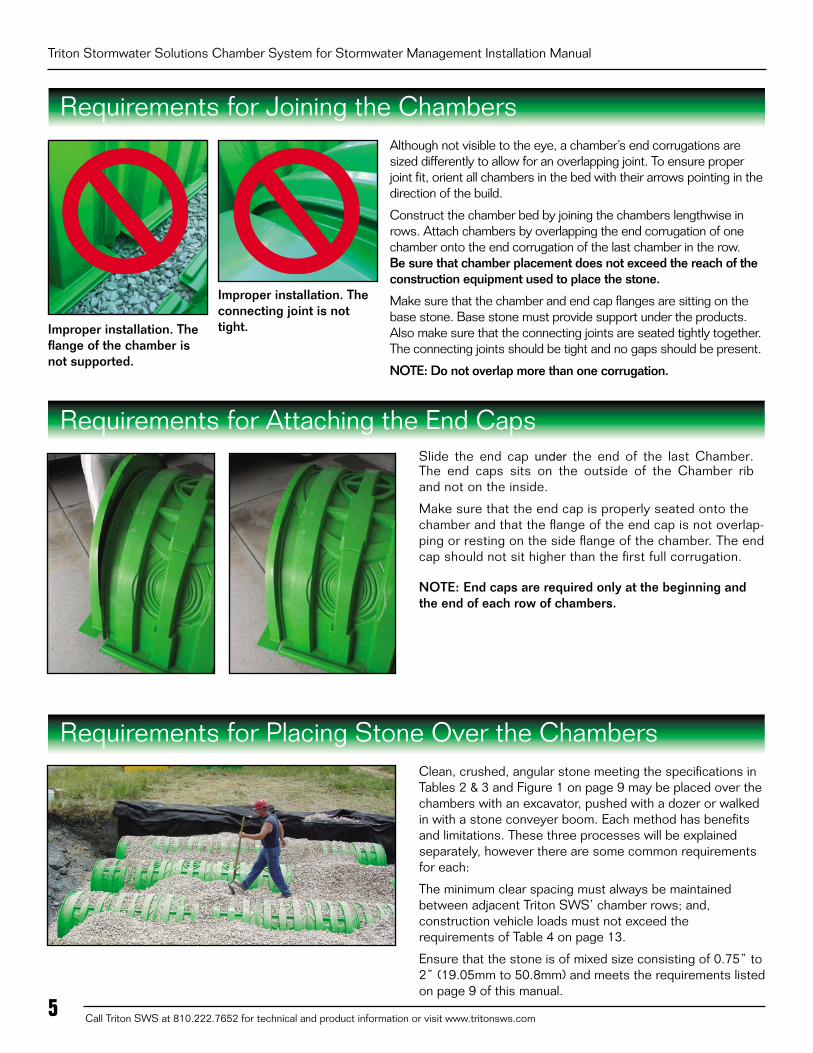
Requirements for Joining the ChambersAlthough not visible to the eye, a chamber’s end corrugations are sized differently to allow for an overlapping joint. To ensure proper joint fit, orient all chambers in the bed with their arrows pointing in the direction of the build.
Construct the chamber bed by joining the chambers lengthwise in rows. Attach chambers by overlapping the end corrugation of one chamber onto the end corrugation of the last chamber in the row. Be sure that chamber placement does not exceed the reach of the construction equipment used to place the stone.
Make sure that the chamber and end cap flanges are sitting on the base stone. Base stone must provide support under the products. Also make sure that the connecting joints are seated tightly together. The connecting joints should be tight and no gaps should be present.
NOTE: Do not overlap more than one corrugation.
Requirements for Attaching the End CapsSlide the end cap under the end of the last Chamber. The end caps sits on the outside of the Chamber rib and not on the inside.
Make sure that the end cap is properly seated onto the chamber and that the flange of the end cap is not overlap-ping or resting on the side flange of the chamber. The end cap should not sit higher than the first full corrugation.
NOTE: End caps are required only at the beginning and the end of each row of chambers.
Requirements for Placing Stone Over the ChambersClean, crushed, angular stone meeting the specifications in Tables 2 & 3 and Figure 1 on page 9 may be placed over the chambers with an excavator, pushed with a dozer or walked in with a stone conveyer boom. Each method has benefits and limitations. These three processes will be explained separately, however there are some common requirements for each:
The minimum clear spacing must always be maintained between adjacent Triton SWS’ chamber rows; and, construction vehicle loads must not exceed the requirements of Table 4 on page 13.
Ensure that the stone is of mixed size consisting of 0.75” to 2” (19.05mm to 50.8mm) and meets the requirements listed on page 9 of this manual.
Improper installation. The flange of the chamber is not supported.
Improper installation. The connecting joint is not tight.

Call Triton SWS at 810.222.7652 for technical and product information or visit www.tritonsws.com 6
Placing stone with an excavator is currently the most common method of placing stone over Triton SWS’ chambers. Its biggest limitation is the reach of the excavator arm. For larger beds it is common practice to work across a bed by joining only a few rows of chambers and placing their angular stone embedment, the filter fabric and soil fill before moving onto the next few rows.
Requirements for Placing Stone with an ExcavatorA bed may be built either parallel to or perpendicular to the chamber row’s direction with this process. The excavator typically works inside the excavation, leading the way across the bed. It is also possible for the excavator to work at grade over the recently placed chambers following the build across. If this process is used it is required that the depth of cover between tops of chambers and the excavator’s tracks be the minimum required by Table 1 on page 8.
1. Anchor chambers by ladling angular stone directly overthe centerline of the chambers. Evenly distribute stoneto minimize chamber movement while maintaining rowseparation distances.
2. After chambers are anchored, continue to place thestone, surrounding the chambers and filling the perim-eter areas to a minimum of 6" (152mm) over the top ofchambers. Stone column height should never differ bymore than 12" (305mm) between adjacent chamber rowsor between chamber rows and perimeter. Do not driveequipment over the chambers without minimum coverrequired by Table 4 on page 13.
3. Repeat steps 1 & 2 until all the chambers are laid to thedimensions of the engineer’s drawing.
Requirements for Pushing Stone with a Dozer
A dozer may be used to push the angular stone embedment into place over the chambers. There are some strict requirements for this process.
1. All embedment stone must be pushed in a directionparallel with the rows of chambers. Pushing stone perpen-dicular across chamber rows may cause the chambers tomove, possibly reducing the required minimum spacingbetween rows. The stone around and between the cham-
Dozer to push stone parallel and ensure stone is distributed equally on sides of chamber. Do not push stone so that one side is being filled with stone while other side has no stone for support. Refer to Backfill of Chambers Diagram on page 15.
Installing embedment stone around chambers.
bers is a critical component to the strength of the overall system so when pushing stone make sure that the amount of stone is evenly distributed and not pushed on one side of the chamber and not the other.
2. Always maintain the required cover between the tops ofchambers and the dozer tracks, per Table 4 on page 13.The contractor must check Table 4 on page 13 to deter-mine if their construction vehicles can be used over thechamber bed.
3. Supply Triton SWS or its distributor with the vehicle specifi-cations that will be used during the installation of the system.
4. Push stone in the opposite directions of the “Build Direc-tion” arrows that are on top of each chamber. Push stonein small piles and spread evenly. Evenly distribute stone tominimize chamber movement while maintaining the properrow separation distances.
5. NEVER push embedment stone perpendicular to the cham-ber row including the Main Header Row. Evenly distributeembedment stone to minimize chamber movement whilemaintaining row separation distances.
6. When entering onto the chamber bed make sure that thereis as flat as possible transition from the existing grade to thestone cover. Push in small piles as to not side load the cham-ber rows. Ensure that the stone fill in between the chamberrow is equalized. Contact Triton SWS for further details.

Triton Stormwater Solutions Chamber System for Stormwater Management Installation Manual
Call Triton SWS at 810.222.7652 for technical and product information or visit www.tritonsws.com7
Requirements for Pushing Stone with a Dozer (cont.)
Requirements for Placing Stone with a Telescoping Conveyer Boom
7. The angular stone cover height between the chamberrows should never differ by more than 12" (304.8mm)over adjacent chambers. Stone should be pushed insmall piles and spread evenly to prevent movement ofchamber rows. Refer to the Backfill of Chamber-Empedi-ment Stone drawing on page 15.
8. Full dump trucks must not drive over or dump stoneover Triton SWS chambers unless there is a mini-mum of 24" (609.6mm) of compacted cover overthe chambers. It is convenient for truckers to dump
stone as close to the dozer as practical, however a full truck is often the heaviest load on a construction site. Raising the body to dump stone significantly increases the rear wheel loads. 24" (609.6mm) of compacted cover is the minimum requirement for dumping stone over Triton SWS’ chambers. The dump truck must be on level ground with adequate soil cover under all tires. Make sure that all tire pressure is to the tire manufacturers’ recommendations. Lower pressure tires must be inflated to the proper pressure before driving over the chamber bed.
Telescoping aggregate conveyer trucks are limited only by the range of the boom. Typical trucks have a boom range between 50’ (15.24m) to 130’ (39.624m). Booms can convey up to 360 cu ft (10.194m3 ) of stone per hour.
1. Anchor chambers by ladling angular stone directly overthe centerline of the chambers. Evenly distribute stoneto minimize chamber movement while maintaining rowseparation distances.
2. After chambers are anchored, continue to place the stone,surrounding the chambers and filling the perimeter areas toa minimum of 6" (152.4mm) over the top of chambers.
Do not drive equipment over the chambers without minimum cover required by Table 4 on page 13. As the stone is being placed over the system, the application of the stone over the products must not be stationary. The conveyer must be moving, left and right, fore and aft, to ensure that the stone is not wearing away the product’s material. The stone must also be installed over the system evenly as described in this manual The maxi-mum height from which stone should be dropped onto the system should not exceed 10" (3m).
3. Repeat steps 1 & 2 above until all the chambers are laidto the dimensions of the engineer’s approved drawings.
Requirements for Backfilling the System1. Place the required angular stone over the entire bed area as
described in previous sections.
2. Line the trench walls with AASHTO M288 Class 2 non-woven filter fabric. Take the fabric from the perimeter andlay it over the top of the stone. The filter fabric must overlapat least 2' (.6096m) where the edges of the fabric meet.
3. The first 12" (304.8mm) of fill material must meet therequirements of Table 3 on page 9. Backfill over the topof the filter fabric in lifts that do not exceed 6" (152.4mm).Distribute the fill with a construction vehicle that meets themaximum wheel loads or ground pressure limits specified inTable 4 on page 13.
4. Compact each lift of backfill as specified in the engineer’sdrawings. Triton SWS requires compacting to a minimumof 95% of the Standard Proctor density. Use a walk-behindor vibratory roller not to exceed a maximum gross vehicleweight of 12,000 lbs (5443.108 kg) and a maximum dy-namic force of 20,000 lbs (9071.847 kg).
5. Continue to backfill over the chamber bed in 6" (152.4mm)maximum lifts until the specified grade is achieved. TritonSWS’ cover requirements are 18" (457mm) minimum and600" (15,240mm) maximum over the top of the chambers.For pavement sub-base or special fill requirements, seeengineer’s drawings.
The backfill height differential should never differ by more than 12" (304.8mm) over adjacent chambers. Minimum cover heights must be met before vehicles are allowed on top of the system. Large rocks and organic matter such as roots, stumps, etc. must not be part of the backfill material. Refer to Table 3 on page 9 for Acceptable Cover Materials or contact the design engineer for approved fill types. Refer to the Back-fill of Chamber-Empediment Stone drawing on page 15.
NOTE: Where site access is limited it is highly recommended to use a rock thrower type of truck shown above.

Call Triton SWS at 810.222.7652 for technical and product information or visit www.tritonsws.com 8
Acceptable Manhole Connection
Acceptable GeotextilesTABLE 1 - Some Suitable Geotextiles
1 AASHTO M288 Class 2 Non-Woven Geotextile Application: Separation layer between angular stone cover and fill to prevent fines intrusion.
2 AASHTO M288 Class 1 Woven Geotextile Application: Stabilization layer for angular stone foundation to prevent scouring of the stone base during JetVac maintenance procedure, modest hydraulic flows maintained. Can also be used in place of the Triton SWS Sediment Floors at each inlet row and Main Header Row to prevent scouring of foundation stone.
Manufacturer AASHTO M288 Class 2 Non-Woven1 AASHTO M288 Class 1 Woven2
Amoco Fabrics and Fibers (Part of BP) ProPex 4506, ProPex 4508, ProPex 4551, ProPex 4552, ProPex 4553
ProPex 2006, ProPex 2016, ProPex 2004
BTL Inc. (Bend Tarp Liners) Style 801, 8 oz., GN200 PPL-20, PPL-24, PPL-36
Carthage Mills FX-60HS, FX-80HS FX-66
Terrafix Geosynthetics Inc. 360R, 400R, 420R 200W, 400W
GSE Lining Technology NW6, NW8 —
Pavco-Amanco NT 3000, NT 4000 TR 4000
SI Geosolution Geotex 601, Geotex 801 Geotex 315ST
TNS Advanced Tech. R060, R070, R080, R100 M 403
US Fabrics US 205NW-C US 315
Webtec TeraTex N06, TeraTex N08 TeraTex HD
Triton Stormwater Solutions Chamber System for Stormwater Management Installation Manual
Call Triton SWS at 810.222.7652 for technical and product information or visit www.tritonsws.com
Washed Crushed Stone Description Criteria
AcceptableAngular Stones have sharp edges and relatively plane sides with unpolished surfaces
Subangular Stones are similar to angular description but have rounded edges
UnacceptableSubrounded Stones have nearly plane sides but have well-rounded corners and edges
Rounded Stones have smoothly curved sides and no edges
9
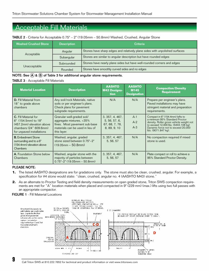
Acceptable Fill MaterialsTABLE 2 - Criteria for Acceptable 0.75" – 2" (19.05mm – 50.8mm) Washed, Crushed, Angular Stone
TABLE 3 - Acceptable Fill Materials
Material Location DescriptionAASHTO
M43 Designa-tion
AASHTO M145
Designation
Compaction/Density Requirement
D. Fill Material from 18” to grade above chambers
Any soil/rock Materials, native soils or per engineer’s plans. Check plans for pavement subgrade requirements.
N/A N/A Prepare per engineer’s plans. Paved installations may have stringent material and preparation requirements.
C. Fill Material for 6" (154.5mm) to 18" (457.2mm) elevation above chambers (24” 609.6mm)for unpaved installations
Granular well-graded soil/ aggregate mixtures, <35% fines. Most pavement sub-base materials can be used in lieu of this layer.
3, 357, 4, 467, 5, 56, 57, 6, 67, 68, 7, 78, 8, 89, 9, 10
A-1
A-2
A-3
Compact in 6" (154.4mm) lefts to a minimum 95% Standard Proctor density. Roller gross vehicle weight not to exceed 12,000 lbs. (5443.108 kg) Dynamic force not to exceed 20,000 lbs. (9071.847 kg).
B. Embedment Stone surrounding and to a 6" (154.4mm) elevation above Chambers
Washed, angular, graded stone sized between 0.75"–2" (19.05mm – 50.8mm)
3, 357, 4, 467, 5, 56, 57
N/A No compaction required if mixed stone is used.
A. Foundation Stone below Chambers
Washed, angular stone with the majority of particles between 0.75"–2" (19.05mm – 50.8mm)
3, 357, 4, 467, 5, 56, 57
N/A Plate compact or roll to achieve a 95% Standard Proctor Density.
PLEASE NOTE: 1. The listed AASHTO designations are for gradations only. The stone must also be clean, crushed, angular. For example, a
specification for #4 stone would state: “clean, crushed, angular no. 4 (AASHTO M43) stone.”
2. As an alternate to Proctor Testing and field density measurements on open graded stone, Triton SWS compaction require-ments are met for “A” location materials when placed and compacted in 9" (229 mm) (max.) lifts using two full passes withan appropriate compactor.
FIGURE 1 - Fill Material Locations
NOTE: See A & B of Table 3 for additional angular stone requirements.
Call Triton SWS at 810.222.7652 for technical and product information or visit www.tritonsws.com 10
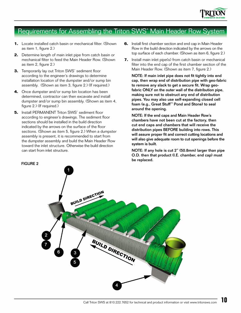
Requirements for Assembling the Triton SWS’ Main Header Row System
1. Locate installed catch basin or mechanical filter. (Shownas item 1, figure 2.)
2. Determine length of main inlet pipe from catch basin ormechanical filter to feed the Main Header Row. (Shownas item 2, figure 2.)
3. Temporarily lay out Triton SWS’ sediment flooraccording to the engineer’s drawings to determineinstallation location of the dumpster and/or sump binassembly. (Shown as item 3, figure 2.) (If required.)
4. Once dumpster and/or sump bin location has beendetermined, contractor can then excavate and installdumpster and/or sump bin assembly. (Shown as item 4,figure 2.) (If required.)
5. Install PERMANENT Triton SWS’ sediment flooraccording to engineer’s drawings. The sediment floorsections should be installed in the build directionindicated by the arrows on the surface of the floorsections. (Shown as item 5, figure 2.) When a dumpsterassembly is present, it is recommended to start fromthe dumpster assembly and build the Main Header Rowtoward the inlet structure. Otherwise the build directioncan start from inlet structure.
6. Install first chamber section and end cap in Main HeaderRow in the build direction indicated by the arrows on thetop surface of each chamber. (Shown as item 6, figure 2.)
7. Install main inlet pipe(s) from catch basin or mechanicalfilter into the end cap of the first chamber section of theMain Header Row. (Shown as item 7, figure 2.)
NOTE: If main inlet pipe does not fit tightly into endcap, then wrap end of distribution pipe with geo-fabricto remove any slack to get a secure fit. Wrap geo-fabric ONLY on the outer wall of the distribution pipe,making sure not to obstruct any end of distributionpipes. You may also use self-expanding closed cellfoam (e.g., Great Stuff™ Pond and Stone) to sealaround the opening.
NOTE: If the end caps and Main Header Row’schambers have not been cut at the factory, thencut end caps and chambers that will receive thedistribution pipes BEFORE building into rows. Thiswill assure proper fit and correct cutting locations andwill also give adequate room to cut openings before thesystem is built.
NOTE: If any hole is cut 2” (50.8mm) larger than pipeO.D. then that product (I.E. chamber, end cap) mustbe replaced.
FIGURE 2

Triton Stormwater Solutions Chamber System for Stormwater Management Installation Manual
Call Triton SWS at 810.222.7652 for technical and product information or visit www.tritonsws.com11
Requirements for Assembling the Triton SWS’ Main Header Row System (Cont.)
FIGURE 3 - Distribution Pipes
8. Continue with installation of chamber sections in thebuild direction indicated by the arrows on the topsurface of each chamber to construct the Main HeaderRow. Chamber sections should fit securely on top of thesediment floor. (Shown as item 8, figure 3.)
9. Once the Main Header Row has been installed ontothe sediment floor and the dumpster, install up to a 33”(838.2mm) O.D. manhole access drop. Use a jigsaw,reciprocating, or air saw to cut the appropriate diameteropening to accept the manhole access drop. Attach foursmall galvanized angle brackets equally spaced approxi-mately ONE (1) foot up from the end of the pipe. Usehalf inch screws on riser pipe to fasten the 4 small gal-vanized brackets. It is not necessary to screw the anglebrackets to the Triton SWS’ chambers. The purpose ofthe angle brackets is to support the pipe until the back-fill is placed. Insert the bottom foot of pipe into the topporthole of the chamber and backfill. Attach top of riserpipe to a “Fernco Type” rubber cap, or to a cleanoutcover assembly, as specified on the engineering draw-ings. Place an access casting in a concrete pad above,once all fill is placed, for risers in pavement. (Shown asitem 9, figure 3.)
10. Locate and cut out specified side porthole diameterson all chambers of the Main Header Row (pre-drill largeenough hole to insert blade for start of cut). (Shown asitem 10, figure 3.)
11. Once all side portholes have been cut to the specifieddiameter, install all distribution pipes. (Shown as item11, figure 3.)
NOTE: If distribution pipes do not fit tightly into sideportholes, then wrap end of distribution pipe withgeo-fabric to remove any slack and get a secure
fit. Wrap geo-fabric ONLY on the outer wall of the distribution pipe, making sure not to obstruct any end of distribution pipe, or you can also use self- expanding closed cell foam (e.g. Great Stuff™ Pond and Stone) to fill in the gaps.
12. Once all distribution pipes have been properly installedin the side portholes of the Main Header Row, set eachchamber of each row aligned with their distribution pipes.Add self-expanding closed cell foam to seal gaps aroundpipe entering through the chambers and end caps. (En-sure the minimum spacing is achieved per the drawings,measured between feet, is required between adjacentrows.) Separate chambers and distribution fittings asnecessary to maintain the minimum clear space betweenchamber rows. Install the end cap onto the first sectionof each row of chambers in the drain field. With a jigsaw,reciprocating saw, or air saw cut an opening for the dis-tribution pipe in the applicable end caps at the specifiedinvert height to accept the distribution pipe. (See Figure4.) Slide chamber with the installed end cap over the endof the distribution pipe. (See Figure 5.) Once chamberspacing requirements are met, the rest of the chambersmaking up the drain field can now be installed. (Shown asitem 12, figure 3.) A minimum of 12" (300mm) spacing isrequired between Main Header Row and distribution rowchambers.
13. Install end caps at the end of each chamber row. (Shownas item 13, figure 3.)
NOTE: End caps are required only at the beginningand end of each row of chambers
In the event that additional sediment floors, dumpster and/or sump bins are to be installed along with manhole access points refer to engineer’s drawings and call Triton SWS for further instructions (1-810-222-7652).

Call Triton SWS at 810.222.7652 for technical and product information or visit www.tritonsws.com 12
Requirements for Assembling the Triton SWS’ Main Header Row System (Cont.)
FIGURE 4 FIGURE 6
FIGURE 7
FIGURE 5
*NOTE: A jig saw works the best to cut hole in end cap
1. Cut Proper Hole diameter on end cap to acceptdistribution pipe at proper invert height.
2. Install End Cap onto first section of each row ofchambers in the drain field.
3. Slide chamber with installed end cap over end ofdistribution pipe or place chamber with installed endcap and pass distribution pipe from inside of chamberthough the end cap hole into the chamber side hole.Use self-expanding closed cell foam to seal aroundgaps between end cap and chamber(s).
Figure 6 shows the distribution pipe projecting past the inside face of the end cap by a minimum of 18” (457.2mm) to supply the chamber row. Base stone can be piled up 8” (203.2mm) on the inside face of the end cap, as shown, to ensure that the flow of water entering into the chamber rows flows toward the end of that row.
Self expanding closed cell foam can be used to fill in the gaps around the distribution pipe. Self expanding foam also can be used to fill in gaps around the pipes from the Main Header Row into the distribution rows (see figure 7).
The Main Header Row feeds water into the distribution rows.
Triton Stormwater Solutions Chamber System for Stormwater Management Installation Manual
Call Triton SWS at 810.222.7652 for technical and product information or visit www.tritonsws.com13
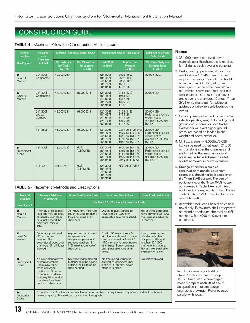
TABLE 4 - Maximum Allowable Construction Vehicle Loads
Material Location
See Figure 1
Fill Depth over
Chambers in [mm]
Maximum Allowable Wheel Loads Maximum Allowable Track Loads6 Maximum Allowable Roller Loads
Max Axle Load for Trucks lbs [kN]
Max Wheel Load for Loaders
lbs [kN]
Track Widthin. [mm]
Max Ground Pressurepsf [kPa]
Max Drum Weight or Dynamic Force
lbs [kN]
D Final Fill Material
36" [900]Compacted
48,000 [213] 12" [305]18" [457]24" [610]30" [762]36" [914]
3863 [185]2652 [127]2088 [100]1691 [81]1462 [70]
38,000 [169]
C Initial Fill Material
24" [600]Compacted
48,000 [213] 16,000 [71] 12" [305]18" [457]24" [610]30" [762]36" [914]
2715 [130]1963 [94]1587 [76]1336 [64]1190 [57]
20,000 [89]
24" [600]Loose/Dumped
48,000 [213] 16,000 [71] 12" [305]18" [457]24" [610]30" [762]36" [914]
2464 [118]1775 [85]1441 [69]1232 [59]1107 [53]
20,000 [89]Roller gross vehicle weight not to exceed 12,000 lbs. [53 kN]
18" [450] 48,000 [213] 16,000 [71] 12" [305]18" [457]24" [610]30" [762]36" [914]
2211 psf [106 kPa]1628 psf [78 kPa]1342 psf [64 kPa]1166 psf [56 kPa]1045 psf [50 kPa]
20,000 [89]Roller gross vehicle weight not to exceed 12,000 lbs. [53 kN]
B Embedment Stone
12" [300] 16,000 [71] NOT ALLOWED
12" [305]18" [457]24" [610]30" [762]36" [914]
1690 psf [81 kPa]1219 psf [58 kPa]1111 psf [53 kPa]1000 psf [48 kPa]924 psf [44 kPa]
20,000 [89]Roller gross vehicle weight not to exceed 12,000 lbs. [53 kN]
6" [150] 8,000 [35] NOT ALLOWED
12" [305]18" [457]24" [610]30" [762]36" [914]
NOT ALLOWED
TABLE 5 - Placement Methods and Descriptions
Material Location
See Figure 1
Placement Methods/ Restrictions
Wheel Load Restrictions Track Load Restrictions Roller Load Restrictions
See Table 6 for Maximum Construction Loads
D Final Fill Material
A variety of placement methods may be used. All construction loads must not exceed the maximum limits in Table 6.
36” (900 mm) minimum cover required for dump trucks to dump over chambers.
Dozers to push parallel to rows until 36" (900mm) compacted cover is reached.4
Roller travel parallel to rows only until 36" (900 mm) compacted cover is reached.
CInitial Fill Material
Excavator positioned off bed recom- mended. Small excavator allowed over chambers. Small dozer allowed.
Asphalt can be dumped into paver when compacted pavement subbase reaches 18” (450 mm) above top of chambers.
Small LGP track dozers & skid loaders allowed to grade cover stone with at least 6” (150 mm) stone under tracks at all times. Equipment must push parallel to rows at all times.
Use dynamic force of roller only after compacted fill depth reaches 12” (300 mm) over chambers. Roller travel parallel to chamber rows only.
B Embedment Stone
No equipment allowed on bare chambers. Use excavator or stone conveyor positioned off bed or on foundation stone to evenly fill around all chambers to at least the top of chambers.
No wheel loads allowed. Material must be placed outside the limits of the chamber bed.
No tracked equipment is allowed on chambers until a min. 6” (150 mm) cover stone is in place.
No rollers allowed.
A Foundation Stone
No restrictions. Contractor responsible for any conditions or requirements by others relative to subgrade bearing capacity, dewatering or protection of subgrade
Notes:1. 36" (900 mm) of stabilized cover
materials over the chambers is requiredfor full dump truck travel and dumping.
2. During paving operations, dump truckaxle loads on 18" (450 mm) of covermay be necessary. Precautions shouldbe taken to avoid rutting of the roadbase layer, to ensure that compactionrequirements have been met, and thata minimum of 18" (450 mm) of coverexists over the chambers. Contact TritonSWS or its distributor for additionalguidance on allowable axle loads duringpaving.
3. Ground pressure for track dozers is thevehicle operating weight divided by totalground contact area for both tracks.Excavators will exert higher groundpressures based on loaded bucketweight and boom extension.
4. Mini-excavators (< 8,000lbs/3,628kg) can be used with at least 12" (300mm) of stone over the chambers andare limited by the maximum groundpressures in Table 4, based on a fullbucket at maximum boom extension.
5. Storage of materials such asconstruction materials, equipment,spoils, etc. should not be located overthe Triton SWS system. The use ofequipment over the Triton SWS systemnot covered in Table 4 (ex. soil mixingequipment, cranes, etc) is limited. Pleasecontact Triton SWS or its distributor formore information.
6. Allowable track loads based on vehicletravel only. Excavators shall not operateon chamber beds until the total backfillreaches 3 feet (900 mm) over theentire bed.
CONSTRUCTION GUIDE
Install non-woven geotextile over stone. Geotextile must overlap 12” (300mm) min. where edges meet. Compact each lift of backfill as specified in the site design engineer’s drawings. Roller to travel parallel with rows.

14Call Triton SWS at 810.222.7652 for technical and product information or visit www.tritonsws.com
LIMITED WARRANTY of Triton Stormwater Solutions (“Triton SWS”): Products
(A) This Limited Warranty (“Limited Warranty”) applies solely to the Triton SWS’ chambers and end caps manufactured for Triton SWS, and sold to the original purchaser (the “Purchaser”). The chambers and end caps are collectively referred to as the “Products.” This Limited Warranty is applicable only to Purchaser and there are no other intended beneficiaries of this Limited Warranty.
(B) The structural integrity of the Products, when installed strictly in accordance with the Triton SWS written installation instructions at the time of installation, are warranted to the Purchaser against defective materials and workmanship for five (5) years from the date of purchase (“Limited Warranty Period”). Should a defect appear in the Limited Warranty Period, the Purchaser shall provide Triton SWS with written notice of the alleged defect at Triton SWS’ corporate headquarters within ten (10) days of the discovery of the defect. The notice shall describe the alleged defect in reasonable detail. Triton SWS agrees to supply replacements for those Products determined by Triton SWS to be defective and covered by this Limited Warranty. The supply of replacement Products is the sole remedy of the Purchaser for breaches of this Limited Warranty. Triton SWS’ liability specifically excludes the cost of removal and/or installation of the Products and/or replacement Products.
(C) THIS LIMITED WARRANTY IS PURCHASER’S EXCLUSIVE WARRANTY. THERE ARE NO OTHER WARRANTIES WITH RESPECT TO THE PRODUCTS, INCLUDING NO IMPLIED WARRANTIES OF MERCHANTABILITY OR OF FITNESS FOR A PARTICULAR PURPOSE.
(D) No representative of Triton SWS has the authority to change this Limited Warranty in any manner or to extend this Limited Warranty. This Limited Warranty does not apply to any person other than to the Purchaser.
(E) Under no circumstances shall Triton SWS be liable to the Purchaser or to any third party for product liability claims; claims arising from the design, shipment, or installation of the Products; or the cost of other goods or services related to the purchase and installation of the Products. For this Limited Warranty to apply, the Products must be installed strictly in accordance with all site conditions required by state and local codes; all other applicable laws; and Triton SWS’ written installation instructions.
(F) THE LIMITED WARRANTY DOES NOT EXTEND TO INCIDENTAL, CONSEQUENTIAL, SPECIAL OR INDIRECT DAMAGES. TRITON SWS SHALL NOT BE LIABLE FOR PENALTIES OR LIQUIDATED DAMAGES, INCLUDING LOSS OF PRODUCTION AND PROFITS; LABOR AND MATERIALS; OVERHEAD COSTS; OR OTHER LOSS OR EXPENSE INCURRED BY THE PURCHASER OR ANY THIRD PARTY. SPECIFICALLY EXCLUDED FROM LIMITED WARRANTY COVERAGE ARE DAMAGE TO THE PRODUCTS ARISING FROM ORDINARY WEAR AND TEAR; ALTERATION, ACCIDENT, MISUSE, ABUSE OR NEGLECT; THE PRODUCTS BEING SUBJECTED TO VEHICLE TRAFFIC OR OTHER CONDITIONS, WHICH ARE NOT PERMITTED BY TRITON SWS’ WRITTEN SPECIFICATIONS OR INSTALLATION INSTRUCTIONS; FAILURE TO MAINTAIN THE MINIMUM GROUND COVERS SET FORTH IN THE INSTALLATION INSTRUCTIONS; THE PLACEMENT OF IMPROPER MATERIALS INTO THE PRODUCTS; FAILURE OF THE PRODUCTS DUE TO IMPROPER SITING OR IMPROPER SIZING; OR ANY OTHER EVENT NOT CAUSED BY TRITON SWS. THIS LIMITED WARRANTY REPRESENTS TRITON SWS’ SOLE LIABILITY TO THE PURCHASER FOR CLAIMS RELATED TO THE PRODUCTS, WHETHER THE CLAIM IS BASED UPON CONTRACT, TORT, OR OTHER LEGAL THEORY.
(G) Claims; Remedies. All claims made under this Limited Warranty shall be presented to Triton SWS in writing at Triton SWS’ corporate headquarters, 9864 E. Grand River, Ste. 110-176, Brighton, Michigan, 48116 no later than ten (10) days after Purchaser’s discovery of defects in the Products for which such claim is made. Any claim under this Limited Warranty that is not so presented to Triton SWS in writing within ten (10) days after discovery shall be deemed unconditionally waived. Triton SWS agrees to replace those Products determined by Triton SWS to be defective and covered by this Limited Warranty. The supply of replacement Products is the sole remedy of Purchaser for breaches of this Limited Warranty. Triton SWS’ liability specifically excludes the cost of removal of the replaced Products and/or installation of the replacement Products.
It is recommended that the Triton SWS’ Products be installed and in the ground within 30 days of delivery at site to prevent onsite damage from equipment and to prevent theft.
Note:
Contact Triton SWS for Lifetime System Warranty Information

Triton Stormwater Solutions Chamber System for Stormwater Management Installation Manual
Call Triton SWS at 810.222.7652 for technical and product information or visit www.tritonsws.com15Triton SWS products are covered by one or more U.S. and Foreign Patents Pending. Printed in U.S.A. © Copyright. All rights reserved. Triton Stormwater Solutions LLC, 2008
MAIN HEADER ROW SECTIONBackfill of Chambers – Embedment Stone
Backfill chambers evenly. Stone column height should never differ by more than 12” (300 mm) between adjacent chamber rows or between chamber rows and perimeter.
Perimeter stone must be brought up evenly with chamber rows. Perimeter must be fully backfilled, with stone extended horizontally to the excavation wall.
UNEVEN BACKFILL EVEN BACKFILL PERIMETER NOT BACKFILLED PERIMETER FULLY BACKFILLED

16Call Triton SWS at 810.222.7652 for technical and product information or visit www.tritonsws.com
Page 6, Items 1 and 6 state to “push stone in small piles as to not side load the chamber rows. Ensure stone fill between the chamber rows do not differ by more than 12” (305mm).”
Page 6, Item 5 states “never push embedment stone perpendicular to the chamber rows.”
Stone must be brought up evenly with chamber rows. Perimeter must be fully backfilled, with stone extending to the trench wall.
Inlet pipe needs to be installed and foamed as soon as possible before stone is place and Bobcat drives over this area. Remove end caps and inspect to see that there are no issues with the chambers as the Bobcat passes over the rows.
End of stone is even across the entire width of system. Must be equalized from side to side to lock stone.
Please make sure the stone is pushed over the system evenly. The end of the stone of the fill needs to be across the entire width of the system in order to lock into the sides of the trench and to keep from side loading the rows that don’t have any stone, as per page 6 of Install Manual. See lower left photo for proper example.
Non-recommended backfilling of system.
Backfilling the system in this manner could result in damage – not recommended.

Triton Stormwater Solutions Chamber System for Stormwater Management Installation Manual
Call Triton SWS at 810.222.7652 for technical and product information or visit www.tritonsws.com17
The stone shown above is a nominal .75” (19.0mm) that had a lot of fines mixed in. Because it is not of mixed size and is of a smaller nominal size than what is called out for in the Triton SWS stone specification, Triton SWS recommends that this stone must be compacted with a walk-behind plate compactor when the stone is placed over the top of the chamber. The plate compactor must not exceed a compaction force greater than 2,500 lbs (10kn). Contact Triton SWS or its distributor for review of stone being used.
The stone shown above shows a mixture of clean, washed, angular stone that ranges between .75” (9mm) to 2.0” (50mm) in size. This is an example of the specified stone that Triton SWS requires. Please refer to page 9 of this manual for further details.
The picture above shows the layout and name of the components of the Triton SWS system. For further information, please visit us at www.tritonsws.com/video.
As shown above, the use of a rock slinger conveyor truck is highly recommended. This type of truck will allow the placement of all the Triton SWS products, connecting pipes, fabric, inlets and prior to backfilling. These trucks can easily convey up to 360 cu. ft. (10.2m3) of stone per hour without any damage to the products. This is a quickest and safest way of backfilling the Triton SWS system.
PROPER STONE USAGE
18Call Triton SWS at 810.222.7652 for technical and product information or visit www.tritonsws.com
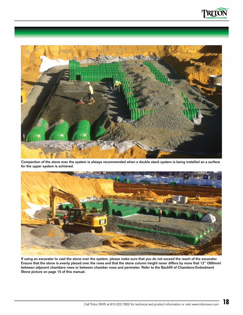
Compaction of the stone over the system is always recommended when a double stack system is being installed so a surface for the upper system is achieved.
If using an excavator to cast the stone over the system, please make sure that you do not exceed the reach of the excavator. Ensure that the stone is evenly placed over the rows and that the stone column height never differs by more that 12” (300mm) between adjacent chambers rows or between chamber rows and perimeter. Refer to the Backfill of Chambers-Embedment Stone picture on page 15 of this manual.