INSTALLATION INSTRUCTIONS SNOWBIRD Rev. 1 Document...
13
Thomas P. Dietrich Hegnacherstr. 43 70736 Fellbach Germany INSTALLATION INSTRUCTIONS SNOWBIRD Rev. 1 Document# RF8001INSI Rev1 INSTALLATION of RF Ski 8001 HUSKYA-1 …. Aircraft
Transcript of INSTALLATION INSTRUCTIONS SNOWBIRD Rev. 1 Document...

Thomas P. Dietrich Hegnacherstr. 43 70736 Fellbach Germany
INSTALLATION INSTRUCTIONS SNOWBIRDRev. 1
Document# RF8001INSI Rev1
INSTALLATION of RF Ski 8001
HUSKYA-1 …. Aircraft
Thomas P. Dietrich Hegnacherstr. 43 70736 Fellbach Germany
INSTALLATION INSTRUCTIONS SNOWBIRD Page IRev. 1
Installation of RF Ski 8001 on Husky A1…. Aircraft
Note:If the installation on another derivate of the A-1 Aircraft (A- 1A, A-1B, A1C 180&200) is carried out, stillfollow these instructions, since the differences between the derivates are not applicable to thisinstallation.
CONTENTS
Page
General
Primary installation
Parts list
Actuator installation, Pump adjustment
Pictures #1 Main ski , hydraulic pump
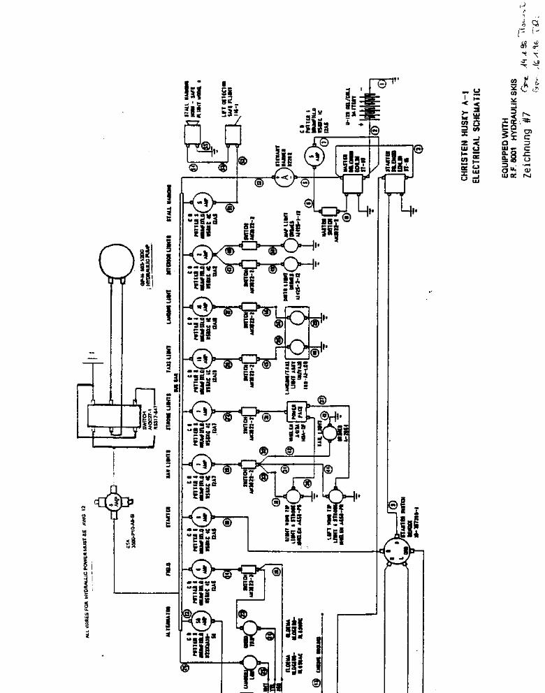
#7 Electrical diagramm
Electrical Wire routing #4
Location of Hydraulic Pump
#6 Front view ski installation
Revision Record
1
2 2/1
3
4
5
6
7
8
9
10
Thomas P. Dietrich Hegnacherstr. 43 70736 Fellbach Germany
INSTALLATION INSTRUCTIONS SNOWBIRD Page 1Rev. 1
Installation of RF Ski 8001
General
The Ski kit contains all necessary parts for installation.It is recommended, if an easy & fast change to the wheel plane is indented, to use an extra Scotttailwheel without ski installed. With this extra tailwheel the airplane ’s configuration can changed veryeasy from wheels to ski and back.
The top side of the skis must be painted with epoxy paint as used on cars, there are no colourrestrictions. The bottom should always be waxed with a Ski downhill wax.
Perform all work according to AC 43.13-1A/3 and methods used in aviation maintenance.
The primary installation has to be approved by an AP. The empty weight of the airplane with andwithout skis has to be added to the flight manual.
After primary installation, the skis may be removed and installed by the pilot, if he got checked out by anAP to perform the job. The pilot will then be responsible for the ski installation. Only the skis will beremoved from the airplane, the Hydraulic pump and the hoses, etc. will remain installed.
If the Husky is already equipped with a hydraulic pump from am Amphib installation, this pump may beused as long as the installer makes sure that the pump will operate the cylinders to their stop. Thisminor change needs to be documented in the POH Supplement.
The RF8001 Skis Hydraulic System is pressure-less, meaning that no pressure is required to maintaineither ski up or down position. Hydraulic pressure is only required for transition of the skis from a “Skiup” to a “Ski down” position.
Engineering aspects approved by
AVIAT INC. Generalvertretung LBA STC approvedThomas P. Dietrich 16.02.96Dipl. Wirt. Ing. STC# 0545/1088 Rev1
Thomas P. Dietrich Hegnacherstr. 43 70736 Fellbach Germany
INSTALLATION INSTRUCTIONS SNOWBIRD Page 2Rev. 1Installation of RF Ski 8001
RequirementsThe Husky airplane must be equipped with 800X6 or 850 X 6 tires inflated to minimum 30 PSI and AviatAero Ski Gear PN 35017-503 or any other approved gear having the same brackets. The 850 X6 is thepreferred tire. If a prop longer than 76 inches is used, the 850 tires are mandatory.
PRIMARY INSTALLATION
Check tire pressure to be 30 PSI min.
1. Remove wheel fairings for 8.00 or 8.50 tires if installed and mount Aviat Ski Hanger Assy 35017-007 on the gear.
2. Install Attachment fittings on Engine mount and float fittings. Do one at a time, otherwise the enginewill deform the mount. Best hang engine on a hoist. Replace Gear stops by new gear stops PN 35001-SGS and plate 35234-001 by 35234-001-Ski.
3. Drill a 3/4 inch hole, at station 19” down from the gear leg into the upper side of the leading edgefairing of the landing gear. Route a red and blue marked hydraulic hose, 1010mm long, inside thelanding gear fairing into the fuselage and connect them with a T fitting. Protect the hose with a rubbergrommet to avoid chafing where it exits the gear fairing.
4. Install hydraulic pump as shown on page #5 with the emergency pump handle to the left with thereservoir pointing backwards. Therefore remove Springs PN 35541-501 and PN 8170. Use existingfloorboard screws to mount the pump in the existing holes.Make sure the pump and the hydraulic lines are not obstructing any controls and the pump is free to beoperated. Connect the Pump lines to the T-Fittings. Always connect matching colour coded lines. HuskyAircraft with a control-stick fairing, need a 3/4 inch hole in the fairing to allow the hydraulic lines to enterthe area in front of the bungees. See Pic Hydraulic pump installation.
5. Fill skis Hydraulic cylinders by pushing the actuator together. Then, dip the front hydraulic line intoFluid 4 and slowly extend the cylinder. Put both skis from front to rear in front of the airplane, put theturnbuckle on rear cable on the side and push airplane over the rear cable. Attach Joke-rodends assy tothe gearbrackets.
6. Install bungee and safety cable on front fitting. Install the rear AN44-34 Eyebolts with the eye facingforward in the float fittings and connect the rear ski cable to the eye. Lift therefore the rear of the ski tolengthen the front bungees. Lifting is best done with a wooden lug 1”X3 “ or similar, 5 ft long.
7. Install tailski on the tailwheel. For quick change setups, an extra tailwheel assy is stronglyrecommended, so that the ski can stay connected to the tailwheel assy.
8. Connect the Hydraulic actuators to the Hydraulic lines by the self sealing quick connectors.Fill pump´s reservoir untill the top.
9. Install selector and gear switch as per electrical drawing on a good visible place in cockpit. Makesure the Pump operates the right way. Gear up should LOWER the Skis, Gear down should raise theskis. Pumping on the manual pump shoud lower the wheels. Cycle skis 4 times to a full stop and refillfluid to the FULL mark, while in the SKI Down / gear up position. Install Placards. No bleedingrequired
10.Perform mass and balance and enter both weights in the airplane flight manual.
Note: If skis are installed, wheelfairings for 800 and 850 tiers can only be installed, if the fairingsare cut-out to allow the joke to operate. It is recommended to use the Wheelfairings for 800, 850 or26” Goodyear tires only without the skis.
Thomas P. Dietrich Hegnacherstr. 43 70736 Fellbach Germany
INSTALLATION INSTRUCTIONS SNOWBIRD Page 2/1Rev. 1
Installations of RF Ski 8001
Changing from SKI TO WHEELS after primary installation.
1. Disconnect rear cable, remove safety cable and bungee.
2. Release pressure from the hydraulic system by running the pump in the direction “gear up” for 2-3seconds. Disconnect hydraulic lines at the quick connectors. Do not make sharp bends with the hoses.
3. Disconnect front cable & bungees & main ski attachment bolts and remove the skis forward.
4. Replace the tailwheel with the ski attached, by a normal tailwheel assembly or remove tailski.
5. Reinstall wheel fairings, if applicable ( 8.00, 850 & 26 Goodyear ’s)
Changing from WHEELS TO SKI after primary installation.
1. Pull airplane over rear cable and insert the skis into the lubed extended Axle assy on the landinggear. Mount with lubed bolts that the threaded side faces the tire.
2. Hook up the bun gees after checking their condition and connect the safety cable.
3. Connect hydraulic lines to the actuators.
4. Attach rear cable
5. Check for right function and for leaks in the hydraulic system.
6. Check entire setup for general condition and hydraulic fluid level.
7. Perform test cycle until both skis touch the ground, then return to the “Wheels down” position
Thomas P. Dietrich Hegnacherstr. 43 70736 Fellbach Germany
INSTALLATION INSTRUCTIONS SNOWBIRD Page 3 Rev.1
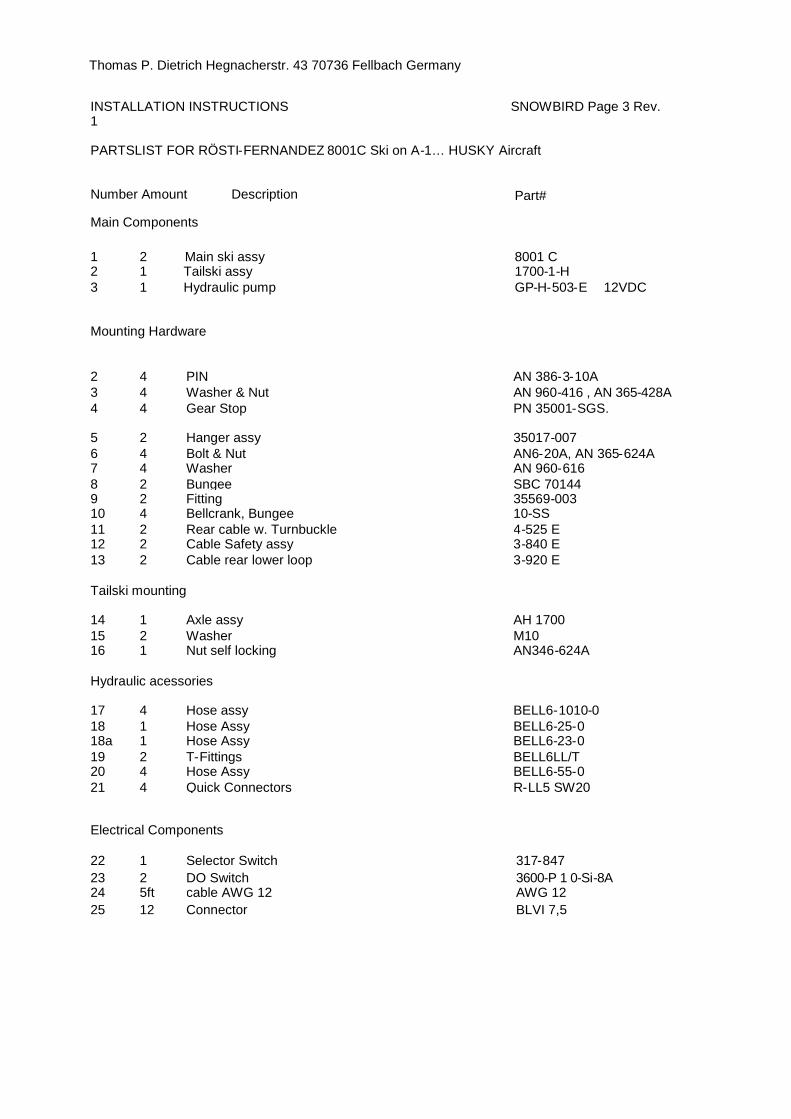
PARTSLIST FOR RÖSTI-FERNANDEZ 8001C Ski on A-1… HUSKY Aircraft
Number Amount Description
Main Components
1 2 Main ski assy
Part#
8001 C2 1 Tailski assy 1700-1-H3 1 Hydraulic pump GP-H-503-E 12VDC
Mounting Hardware
2 4 PIN AN 386-3-10A3 4 Washer & Nut AN 960-416 , AN 365-428A4 4 Gear Stop PN 35001-SGS.
5 2 Hanger assy 35017-0076 4 Bolt & Nut AN6-20A, AN 365-624A7 4 Washer AN 960-6168 2 Bungee SBC 701449 2 Fitting 35569-00310 4 Bellcrank, Bungee 10-SS11 2 Rear cable w. Turnbuckle 4-525 E12 2 Cable Safety assy 3-840 E13 2 Cable rear lower loop 3-920 E
Tailski mounting
14 1 Axle assy AH 170015 2 Washer M1016 1 Nut self locking AN346-624A
Hydraulic acessories
17 4 Hose assy BELL6-1010-018 1 Hose Assy BELL6-25-018a 1 Hose Assy BELL6-23-019 2 T-Fittings BELL6LL/T20 4 Hose Assy BELL6-55-021 4 Quick Connectors R-LL5 SW20
Electrical Components
22 1 Selector Switch 317-84723 2 DO Switch 3600-P 1 0-Si-8A24 5ft cable AWG 12 AWG 1225 12 Connector BLVI 7,5

Thomas P. Dietrich Hegnacherstr. 43 70736 Fellbach Germany
INSTALLATION INSTRUCTIONS SNOWBIRD Page 4Rev. 1
Installations of RF Ski 8001
ACTUATOR INSTALLATION
In case that the hydraulic actuator needs to be removed and installed, it is most important to checkthe fully extended length of the actuator.
1. Move the Joke backwards in the Ski UP position. The stops must touch the ski.2. Disconnect the actuator from hydraulic lines and extend the actuator manually to full length.3. Screw the actuator into the bulkhead of the ski. Minimum 6 turns. Try to insert the slotted fitting
on the end of the actuator into the attachment bolt on the U-brace. Adjust the extended cylinderlength by screwing the cylinder further into the ski or by repositioning the slotted fitting on theactuator.
4. The forward facing end of the slotted fitting should not touch the bolt on the U- brace,but have 0.02 inch clearance when the actuator is fully extended.
5. After checking the actuator length, secure all bolts and Nuts with safety lacquer
NOTE: IF ACTUATOR LENGTH IS ADJUSTED TOO LONG, THE ACTUATOR WILL DESTROYITSELF AND THE ACTUATOR ROD WILL BENT.
Pump Pressure adjustment.
The hydraulic pressure of the pump may by adjusted for both pump directions separately. Theadjustment screws are in the recessed holes left and right of the filler opening. There is a white Derlrinplug to protect the screws.To adjust pressure, remove the plugs.By turning the screws in with an Allen head tool, the pressure will increase in the respective direction.
Adjust pressure , that the aircraft is pulled by the pump onto and off the skis, at MTOW on flat evenground.
By adjusting the pressure too high, the flow gets a bit slower, but there in no harm to the system.

GermanyThomas P. Dietrich Hegnacherstr. 43 70736Fellbach
INSTALLATION INSTRUCTIONSRev. 1
Document# RF8001INSI Rev1
SNOWBIRD
Revision Record
Revision NumberPages affected description of change date

Rev1 all Editorial 23.1.08Doc# RF8001INSTI assigned

Thomas P. Dietrich Hegnacherstr. 43 70736 Fellbach Germany
INSTALLATION INSTRUCTIONS SNOWBI RDRev. 1
Page #5
Picture #1
Main Ski Installation.

Panel viewed from front, SWITCH Position I
Cable RoutingRoute cables along the diagonal strut to theforward right top cluster, we the enginemount is connected. Continue down theside diagonal strut to the forward landinggear attachment point. Route
cables forward, on outside of lower RHIongeron to the pump
. G P 1 - t - & 0 3 C - k 1 2 v D c ~ ~~
' ~ o u ~~~. S oS C~Qec ~ c ~ C c c `~,~ 4 n ~I,lS~~1 _ J
les to tubing by double wrap cable ties.b
1 r t I . wm (1P ? . fr ____r . r 1 . ` I
Aa.lp~/t
1 . s + i r
#4
I
Side view front fuselage
Top view front fuselage

Thomas P. Dietrich Hegnacherstr. 43 70736 Fellbach Germany
INSTALLATION INSTRUCTIONS SNOWBI RDRev. 1
Page #9
Picture #6
Front Lower Cowl Cutout
Station 19” for drilling Hydraulic hose outlet