Installation Instructions for: INTERCOOLED SUPERCHARGER ... · INSTALLATION MANUAL Magna Charger GM...
42
Step-by-step instructions for installing the best in supercharger systems. Installation Instructions for: INTERCOOLED SUPERCHARGER SYSTEM 2004 LS1 PONTIAC GTO Magnuson Products LLC 1990 Knoll Drive, Bldg A, Ventura, CA. 93003 (805) 289-0044 * (805) 677-4897 fax magnusonproducts.com * magnacharger.com ATTENTION! Your MAGNA CHARGER intercooler kit is sensitive to corrosion! Take care of if by using 50/50 anti-freeze with de-ionized water. 89-89-60-013 Rev L 89-89-60-013 Rev L * PREMIUM FUEL REQUIRED * * PREMIUM FUEL REQUIRED *
Transcript of Installation Instructions for: INTERCOOLED SUPERCHARGER ... · INSTALLATION MANUAL Magna Charger GM...
Step-by-step instructions for installing the best in supercharger systems.
Installation Instructions for:
INTERCOOLED SUPERCHARGER SYSTEM 2004 LS1 PONTIAC GTO
Magnuson Products LLC1990 Knoll Drive, Bldg A, Ventura, CA. 93003
(805) 289-0044 * (805) 677-4897 faxmagnusonproducts.com * magnacharger.com
ATTENTION!Your MAGNA CHARGER intercooler kit
is sensitive to corrosion! Take care of if by using 50/50
anti-freeze with de-ionized water.
89-89-60-013 Rev L89-89-60-013 Rev L
* PREMIUM FUEL REQUIRED ** PREMIUM FUEL REQUIRED *

INSTALLATION MANUALMagna ChargerGM 5.7L Engine
2004 Pontiac GTO
Please take a few moments to review this manual thoroughly before you begin work: Make a quick parts check to make certain your kit is complete (see shipper parts list in this package). If you discover shipping damage or shortage, please call our offi ce immediately. Take a look at exactly what you are going to need in terms of tools, time, and experience. Review our limited warranty with care. When unpacking the supercharger kit DO NOT lift the supercharger assembly by the black plastic bypass actuator. This is pre-set from the factory and can be altered if used as a lifting point!
Caution: Relieve the fuel system pressure before servicing fuel system components in order to reduce the risk of fi re and personal injury. After relieving the system pressure, a small amount of fuel may be released when servicing the fuel lines or connections. In order to reduce the risk of personal injury, cover the regulator and fuel line fi ttings with a shop towel before disconnecting. This will catch any fuel that may leak out. Place the towel in an approved container when the job is complete. Use only premium fuel, 91 octane or better.Use only premium fuel, 91 octane or better.
Magnuson Supercharger systems are manufactured to produce about 20 RWHP per pound of boost at sea level. High altitudes will produce different numbers.
Our Magnuson Supercharger kits are designed for engines in good mechanical condition only. Installation on high mileage or damaged engines is not recommended and may result in engine failure, for which we are not responsible. Magna Charger is not responsible for the engine or consequential damages.
Aftermarket engine recalibration devices that modify fuel and spark curve (including, but not limited to programmers) are not recommended and may cause engine damage or failure. Use of non-Magnuson Supercharger approved programming will void all warranties. If you have any questions, call us.
After you fi nish your installation and road test your vehicle, please fi ll out and mail in the limited warranty card, so we can add you to our fi les (this is important for your protection).
A new GM fuel fi lter is recommended at the time of supercharger installation Stock spark plugs and stock plug gap is recommended Drive belt = Gates# K061010 Air Filter = K&N# 33-2289
Tools Required: Metric wrench set ¼” - 3/8” and ½” drive metric socket set (Standard & Deep) 3/8”and ½” drive Foot pound and inch pound torque wrenches Phillips and fl at head screwdrivers Fuel line quick disconnect tools (included in kit) Small or angled 3/8” drill motor Drain pan Hose cutters Hose clamp pliers Safety glasses Metric Allen socket set 3/8” drive Shop vacuum cleanerHelpful Tools: Electric or air driven impact wrench.
Contact information:Magnuson Products LLCMagna Charger Division1990 Knoll Drive, Bldg AVentura, CA 93003Sales/Tech support 805-289-0044Websites:www.magnusonproducts.comwww.magnacharger.comEmail:[email protected]

4. Open the petcock on the bottom of the driver side of the radiator to drain the fl uid. Drain into a clean pan for reuse later. We suggest you pour it into suitable bottles with caps, and use a strainer when you reuse the fl uid to remove any debris.
3. On top of each shock tower remove the two nuts that secure the strut tower brace with a 13mm socket wrench. Remove the strut tower brace and fasteners from the vehicle, the brace can be reinstalled after the supercharger installation.
1. Open the hood and remove the under hood insulation by prying out the seven plastic buttons that retain it. The insulation will not be reused.
2. Start the supercharger installation by removing the negative (-) battery with a 10mm wrench.
2004 Pontiac GTO LS1
03/15 Page 3 www.magnusonproducts.com
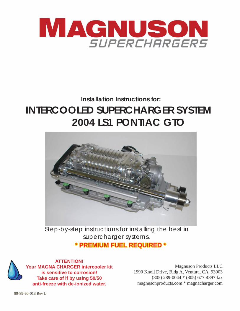
5. Remove the two engine covers by pulling up fi rmly along the edges.
6. Loosen the Air Tube clamp at the Mass Air Flow meter. (MAF)
7. Loosen the Air Tube clamp at the throttle body.
8. Disconnect the Intake Air Temperature (IAT) connector from the sensor.
2004 Pontiac GTO LS1
03/15 Page 4 www.magnusonproducts.com
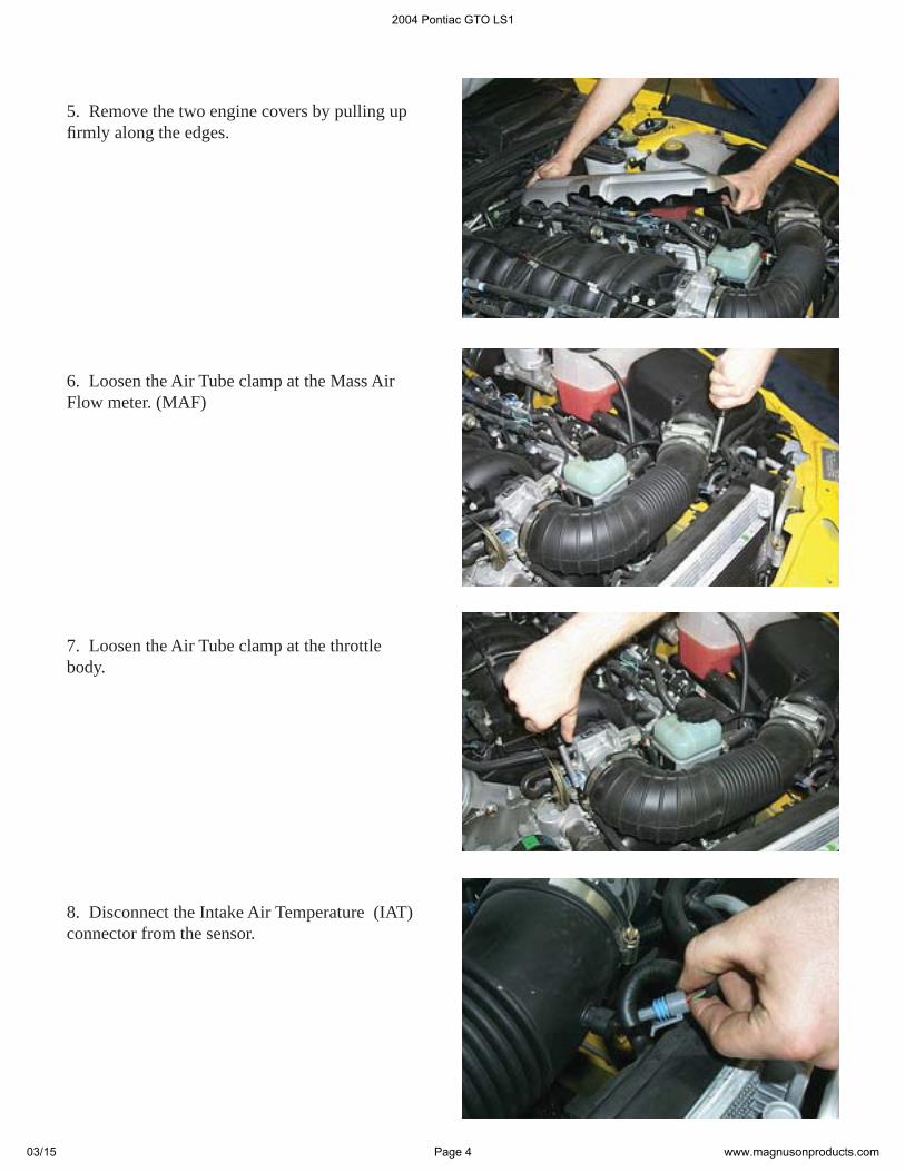
10. Remove the air tube completely, it will not be re-used.
11. Rotate the throttle arm to the open position and then remove the throttle cable from the arm by aligning the cable with the slot in the side of the arm.
12. Remove the throttle cable from its bracket by depressing the small lock tab with a screwdriver and then pulling up on the cable.
ScrewdriverScrewdriver
9. Remove the IAT sensor from the air tube.
2004 Pontiac GTO LS1
03/15 Page 5 www.magnusonproducts.com
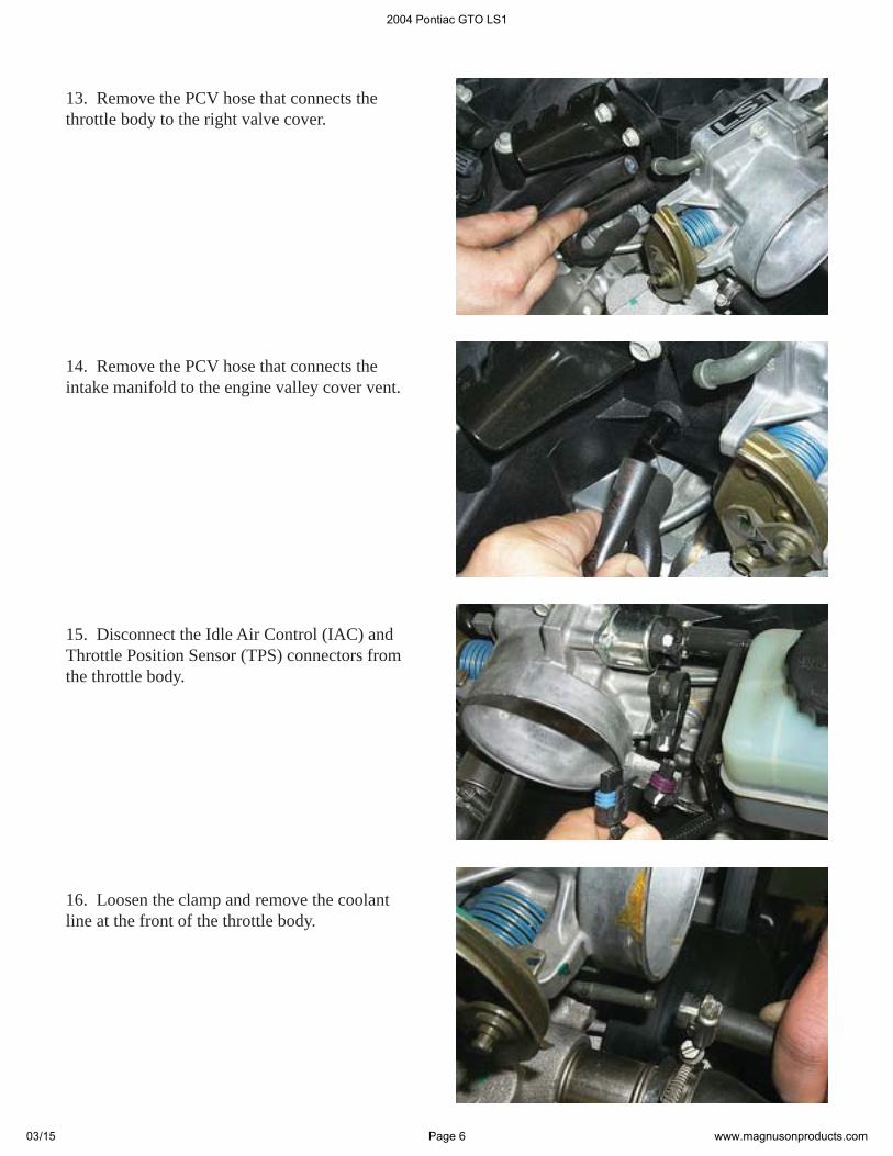
13. Remove the PCV hose that connects the throttle body to the right valve cover.
14. Remove the PCV hose that connects the intake manifold to the engine valley cover vent.
15. Disconnect the Idle Air Control (IAC) and Throttle Position Sensor (TPS) connectors from the throttle body.
16. Loosen the clamp and remove the coolant line at the front of the throttle body.
2004 Pontiac GTO LS1
03/15 Page 6 www.magnusonproducts.com
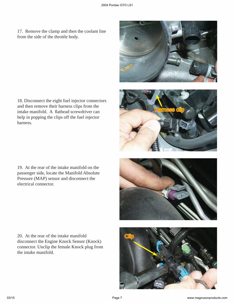
19. At the rear of the intake manifold on the passenger side, locate the Manifold Absolute Pressure (MAP) sensor and disconnect the electrical connector.
20. At the rear of the intake manifold disconnect the Engine Knock Sensor (Knock) connector. Unclip the female Knock plug from the intake manifold.
ClipClip
18. Disconnect the eight fuel injector connectors and then remove their harness clips from the intake manifold. A fl athead screwdriver can help in popping the clips off the fuel injector harness.
Harness clipHarness clip
17. Remove the clamp and then the coolant line from the side of the throttle body.
2004 Pontiac GTO LS1
03/15 Page 7 www.magnusonproducts.com
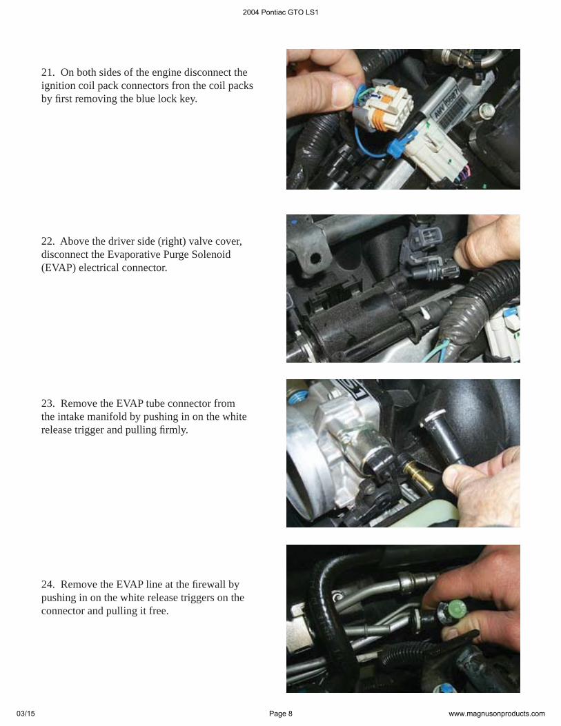
21. On both sides of the engine disconnect the ignition coil pack connectors fron the coil packs by fi rst removing the blue lock key.
22. Above the driver side (right) valve cover, disconnect the Evaporative Purge Solenoid (EVAP) electrical connector.
23. Remove the EVAP tube connector from the intake manifold by pushing in on the white release trigger and pulling fi rmly.
24. Remove the EVAP line at the fi rewall by pushing in on the white release triggers on the connector and pulling it free.
2004 Pontiac GTO LS1
03/15 Page 8 www.magnusonproducts.com
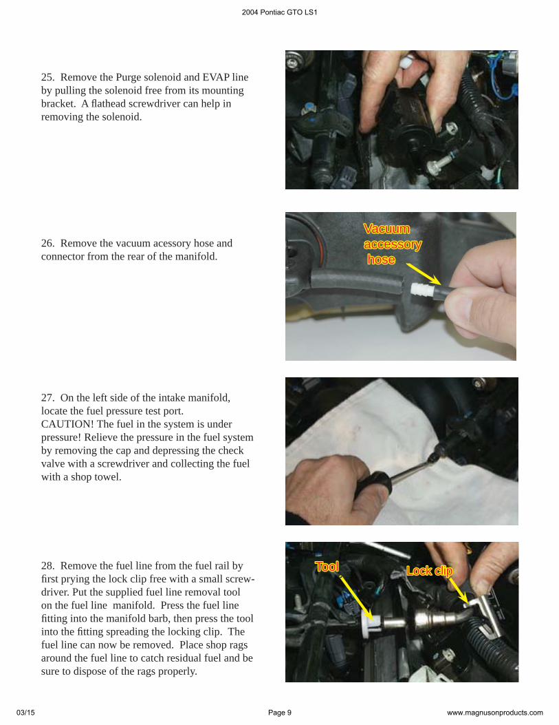
25. Remove the Purge solenoid and EVAP line by pulling the solenoid free from its mounting bracket. A fl athead screwdriver can help in removing the solenoid.
28. Remove the fuel line from the fuel rail by fi rst prying the lock clip free with a small screw-driver. Put the supplied fuel line removal tool on the fuel line manifold. Press the fuel line fi tting into the manifold barb, then press the tool into the fi tting spreading the locking clip. The fuel line can now be removed. Place shop rags around the fuel line to catch residual fuel and be sure to dispose of the rags properly.
26. Remove the vacuum acessory hose and connector from the rear of the manifold.
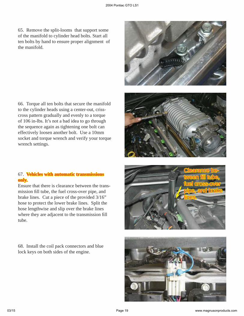
27. On the left side of the intake manifold, locate the fuel pressure test port. CAUTION! The fuel in the system is under pressure! Relieve the pressure in the fuel system by removing the cap and depressing the check valve with a screwdriver and collecting the fuel with a shop towel.
ToolTool Lock clipLock clip
VacuumVacuumaccessoryaccessory hose hose
2004 Pontiac GTO LS1
03/15 Page 9 www.magnusonproducts.com
29. At the rear of the intake manifold remove the vacuum brake hose by squeezing the clamp and pulling the hose free. Alternately, you can remove the hose from the brake booster cannister by pulling the fi tting out of the grommet...and snake the hose out when the manifold is removed.
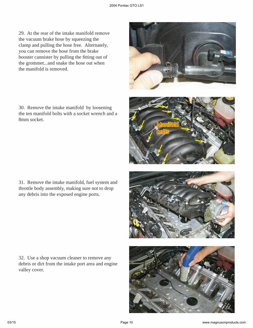
30. Remove the intake manifold by loosening the ten manifold bolts with a socket wrench and a 8mm socket.
31. Remove the intake manifold, fuel system and throttle body assembly, making sure not to drop any debris into the exposed engine ports.
32. Use a shop vacuum cleaner to remove any debris or dirt from the intake port area and engine valley cover.
ManifoldManifoldboltsbolts
2004 Pontiac GTO LS1
03/15 Page 10 www.magnusonproducts.com
33. Cover the intake ports with tape or clean rags to keep dirt and debris from entering the engine. We’ve found that painters masking tape works well and doesn’t leave a lot of residue.
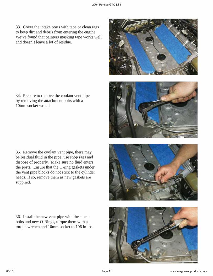
35. Remove the coolant vent pipe, there may be residual fl uid in the pipe, use shop rags and dispose of properly. Make sure no fl uid enters the ports. Ensure that the O-ring gaskets under the vent pipe blocks do not stick to the cylinder heads. If so, remove them as new gaskets are supplied.
36. Install the new vent pipe with the stock bolts and new O-Rings, torque them with a torque wrench and 10mm socket to 106 in-lbs.
34. Prepare to remove the coolant vent pipe by removing the attachment bolts with a 10mm socket wrench.
2004 Pontiac GTO LS1
03/15 Page 11 www.magnusonproducts.com
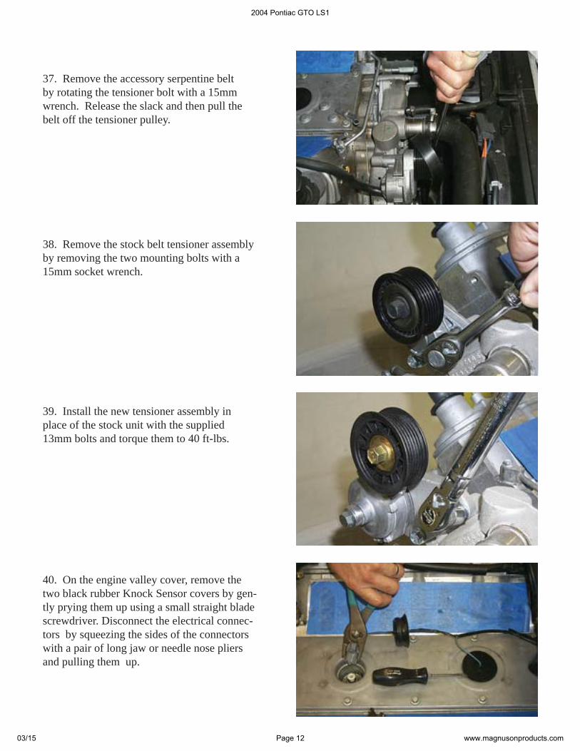
37. Remove the accessory serpentine belt by rotating the tensioner bolt with a 15mm wrench. Release the slack and then pull the belt off the tensioner pulley.
39. Install the new tensioner assembly in place of the stock unit with the supplied 13mm bolts and torque them to 40 ft-lbs.
40. On the engine valley cover, remove the two black rubber Knock Sensor covers by gen-tly prying them up using a small straight blade screwdriver. Disconnect the electrical connec-tors by squeezing the sides of the connectors with a pair of long jaw or needle nose pliers and pulling them up.
38. Remove the stock belt tensioner assembly by removing the two mounting bolts with a 15mm socket wrench.
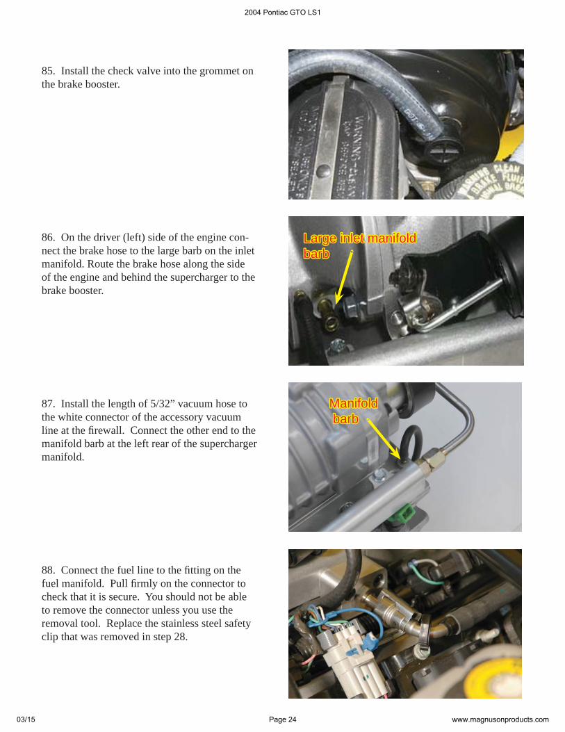
2004 Pontiac GTO LS1
03/15 Page 12 www.magnusonproducts.com

41. Remove the Knock sensors by using a ratchet and a deep 22mm or a 7/8” socket.
43. The gasket will be reused, the original valley cover will not. Inspect the gasket for any damage, carefully clean the gasket as well as the mating surface on the block. Then re-install, note that it will only fi t correctly in one position.
44. Install the new valley cover using the sup-plied fl athead bolts with a 5mm Allen socket and torque wrench. Torque the bolts to 15ft-lbs. Place a couple of small dots of RTV Silicon in the recesses of the valley cover and insert the six O-rings supplied. The RTV Silicone will hold the O-rings in place. Do not disturb until the RTV sets up. O-ringsO-rings
GasketGasket
42. Remove the engine valley cover and gasket by removing the ten bolts with a 10mm socket wrench.
2004 Pontiac GTO LS1
03/15 Page 13 www.magnusonproducts.com
45. Re-install the knock sensors and torque them to 15 ft-lbs. Re-attach the electrical con-nectors by pushing the connectors down fi rmly until a “click” is heard. Before installing the covers, apply a bead of silicone adheasive to the sides of the covers. Finally push the covers back into place and do not disturb until the silicone sets up.
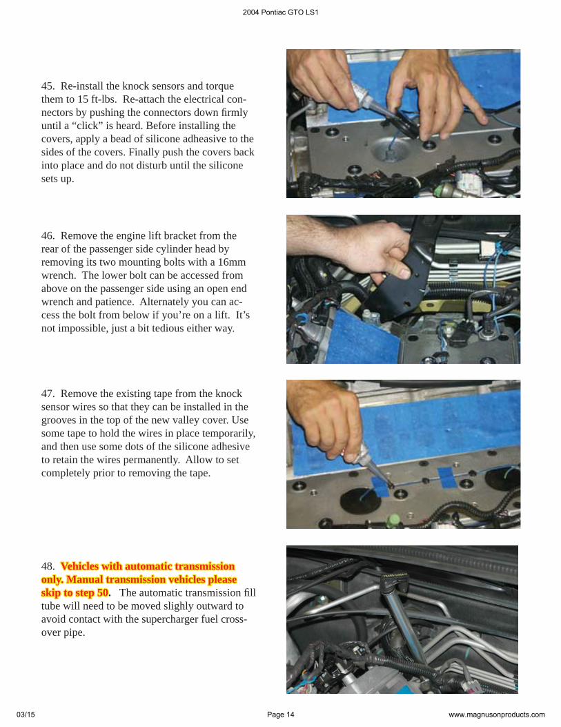
47. Remove the existing tape from the knock sensor wires so that they can be installed in the grooves in the top of the new valley cover. Use some tape to hold the wires in place temporarily, and then use some dots of the silicone adhesive to retain the wires permanently. Allow to set completely prior to removing the tape.
46. Remove the engine lift bracket from the rear of the passenger side cylinder head by removing its two mounting bolts with a 16mm wrench. The lower bolt can be accessed from above on the passenger side using an open end wrench and patience. Alternately you can ac-cess the bolt from below if you’re on a lift. It’s not impossible, just a bit tedious either way.
48. Vehicles with automatic transmission Vehicles with automatic transmission only. Manual transmission vehicles please only. Manual transmission vehicles please skip to step 50skip to step 50. The automatic transmission fi ll tube will need to be moved slighly outward to avoid contact with the supercharger fuel cross-over pipe.
2004 Pontiac GTO LS1
03/15 Page 14 www.magnusonproducts.com
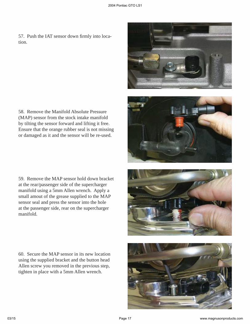
51. Using the four crimp/shrink connectors and the two pieces of 63” long white wire supplied, extend the IAT wires. Install the crimp/shrink connectors by stripping a 1/4” of insulation off each end of the wires. Insert one end of the wire into the crimp shrink connector and crimp it securely. Using a heat gun or blow-dryer set on high, shrink the plastic covering of the connec-tor until the clear sealant from the inside of the connector can be seen oozing out from under the plastic covering. Crimping the con-nector alone is not enough to ensure a permanent connection; you must shrink the plastic covering! When you are fi nished cover the wires and connectors with the piece of split loom supplied.
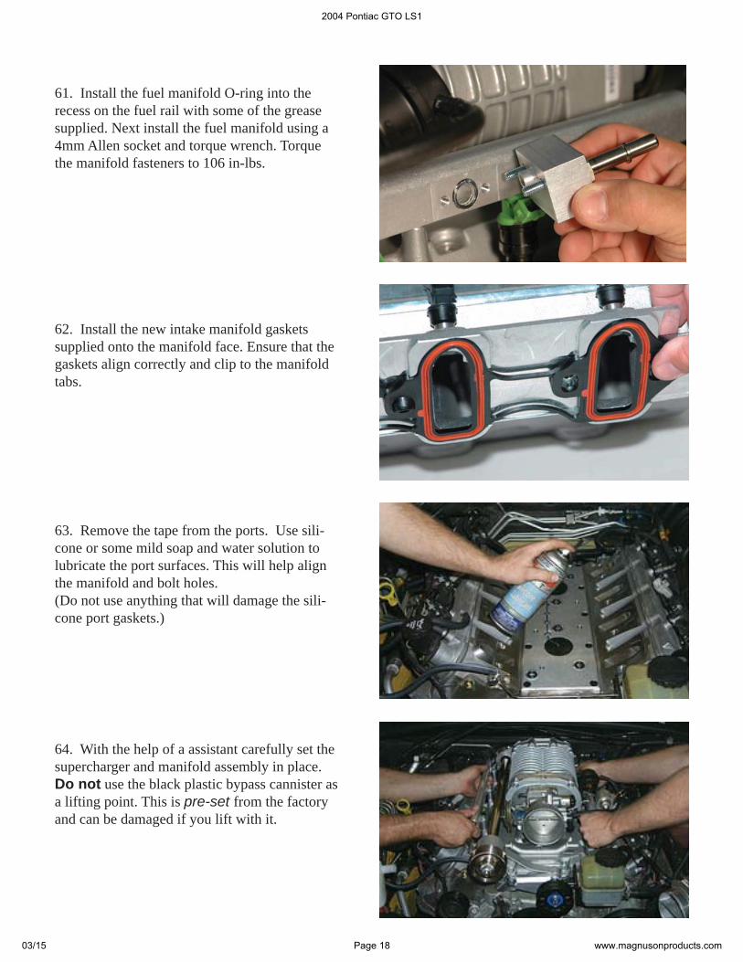
52. Remove the throttle body by removing its three mounting bolts with a 10mm socket wrench.
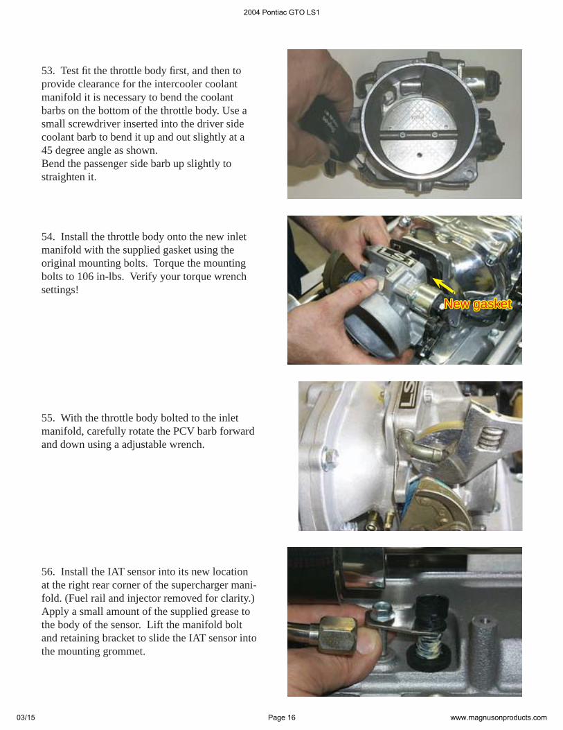
50. Locate the IAT connector and cut its wires approximately 3” from the plug. Save the con-nector for re-use.
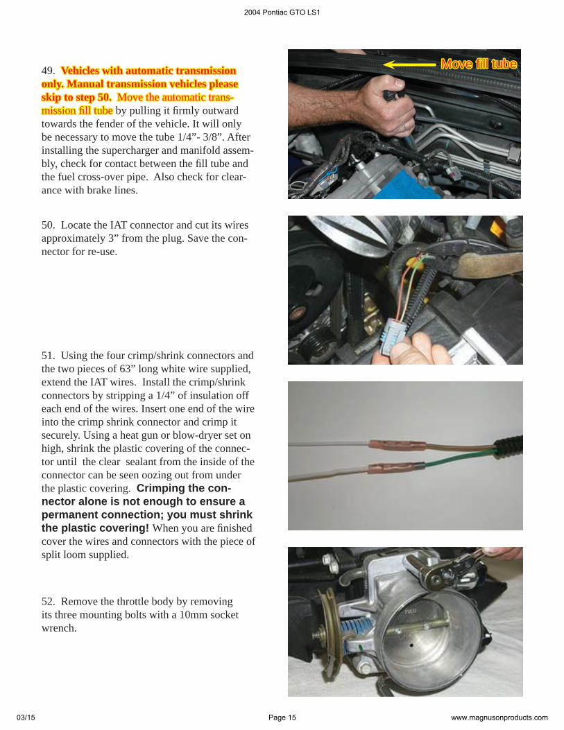
49. Vehicles with automatic transmission Vehicles with automatic transmission only. Manual transmission vehicles please only. Manual transmission vehicles please skip to step 50. skip to step 50. Move the automatic trans-Move the automatic trans-mission fi ll tubemission fi ll tube by pulling it fi rmly outward towards the fender of the vehicle. It will only be necessary to move the tube 1/4”- 3/8”. After installing the supercharger and manifold assem-bly, check for contact between the fi ll tube and the fuel cross-over pipe. Also check for clear-ance with brake lines.
Move fi ll tubeMove fi ll tube
2004 Pontiac GTO LS1
03/15 Page 15 www.magnusonproducts.com
54. Install the throttle body onto the new inlet manifold with the supplied gasket using the original mounting bolts. Torque the mounting bolts to 106 in-lbs. Verify your torque wrench settings!
New gasketNew gasket
55. With the throttle body bolted to the inlet manifold, carefully rotate the PCV barb forward and down using a adjustable wrench.
53. Test fi t the throttle body fi rst, and then to provide clearance for the intercooler coolant manifold it is necessary to bend the coolant barbs on the bottom of the throttle body. Use a small screwdriver inserted into the driver side coolant barb to bend it up and out slightly at a 45 degree angle as shown.Bend the passenger side barb up slightly to straighten it.
56. Install the IAT sensor into its new location at the right rear corner of the supercharger mani-fold. (Fuel rail and injector removed for clarity.) Apply a small amount of the supplied grease to the body of the sensor. Lift the manifold bolt and retaining bracket to slide the IAT sensor into the mounting grommet.
2004 Pontiac GTO LS1
03/15 Page 16 www.magnusonproducts.com
59. Remove the MAP sensor hold down bracket at the rear/passenger side of the supercharger manifold using a 5mm Allen wrench. Apply a small amout of the grease supplied to the MAP sensor seal and press the sensor into the hole at the passenger side, rear on the supercharger manifold.
60. Secure the MAP sensor in its new location using the supplied bracket and the button head Allen screw you removed in the previous step, tighten in place with a 5mm Allen wrench.
58. Remove the Manifold Absolute Pressure (MAP) sensor from the stock intake manifold by tilting the sensor forward and lifting it free. Ensure that the orange rubber seal is not missing or damaged as it and the sensor will be re-used.
57. Push the IAT sensor down fi rmly into loca-tion.
2004 Pontiac GTO LS1
03/15 Page 17 www.magnusonproducts.com
63. Remove the tape from the ports. Use sili-cone or some mild soap and water solution to lubricate the port surfaces. This will help align the manifold and bolt holes.(Do not use anything that will damage the sili-cone port gaskets.)
61. Install the fuel manifold O-ring into the recess on the fuel rail with some of the grease supplied. Next install the fuel manifold using a 4mm Allen socket and torque wrench. Torque the manifold fasteners to 106 in-lbs.
62. Install the new intake manifold gaskets supplied onto the manifold face. Ensure that the gaskets align correctly and clip to the manifold tabs.
64. With the help of a assistant carefully set the supercharger and manifold assembly in place. Do not use the black plastic bypass cannister as a lifting point. This is pre-set from the factory and can be damaged if you lift with it.
2004 Pontiac GTO LS1
03/15 Page 18 www.magnusonproducts.com
68. Install the coil pack connectors and blue lock keys on both sides of the engine.
65. Remove the split-looms that support some of the manifold to cylinder head bolts. Start all ten bolts by hand to ensure proper alignment of the manifold.
66. Torque all ten bolts that secure the manifold to the cylinder heads using a center-out, criss-cross pattern gradually and evenly to a torque of 106 in-lbs. It’s not a bad idea to go through the sequence again as tightening one bolt can effectively loosen another bolt. Use a 10mm socket and torque wrench and verify your torque wrench settings.
67. Vehicles with automatic transmissions Vehicles with automatic transmissions only.only.Ensure that there is clearance between the trans-mission fi ll tube, the fuel cross-over pipe, and brake lines. Cut a piece of the provided 3/16” hose to protect the lower brake lines. Split the hose lengthwise and slip over the brake lines where they are adjacent to the transmission fi ll tube.
Clearance be-Clearance be-tween fi ll tube, tween fi ll tube, fuel cross-over fuel cross-over pipe, and brake pipe, and brake lines.lines.
2004 Pontiac GTO LS1
03/15 Page 19 www.magnusonproducts.com
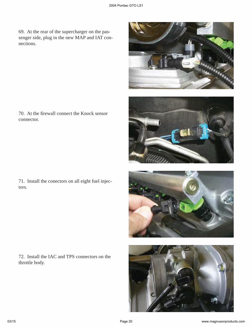
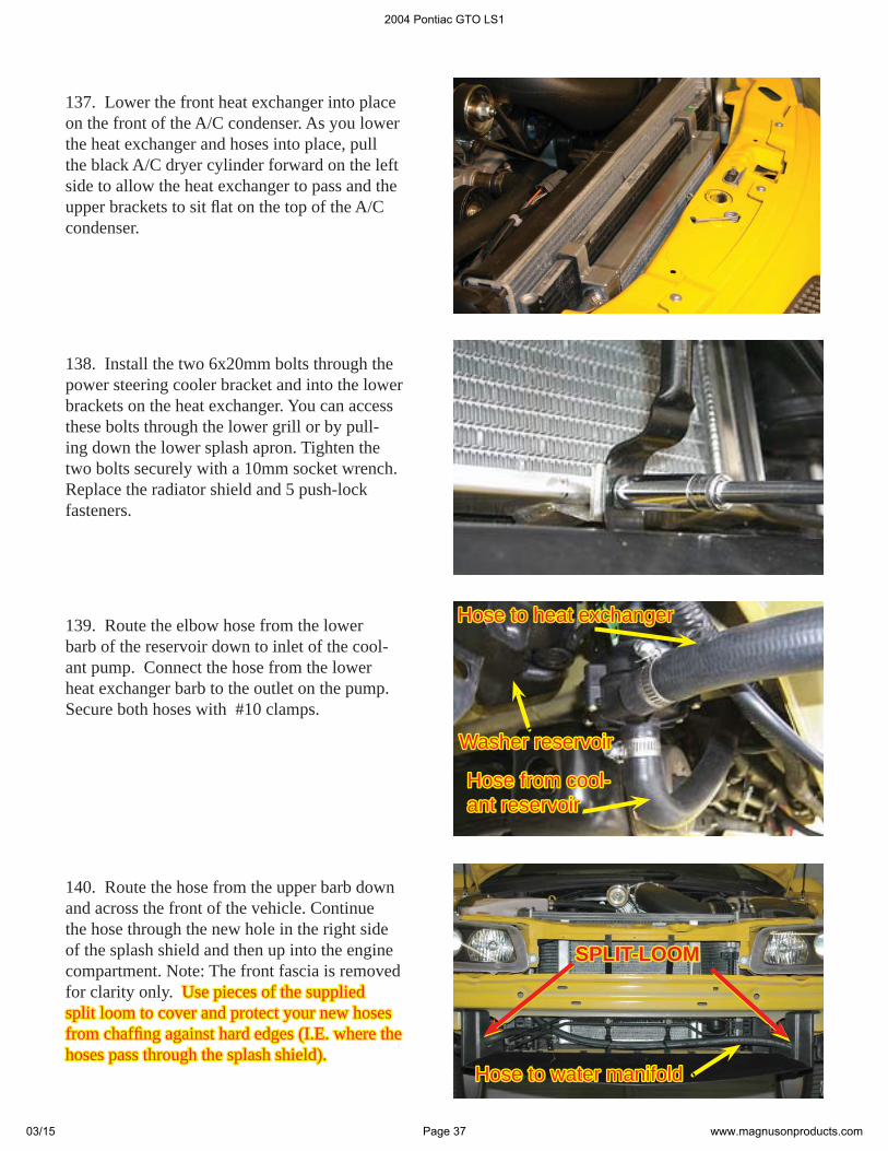
70. At the fi rewall connect the Knock sensor connector.
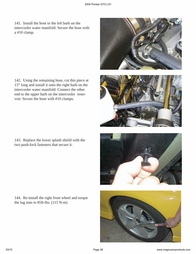
71. Install the conectors on all eight fuel injec-tors.
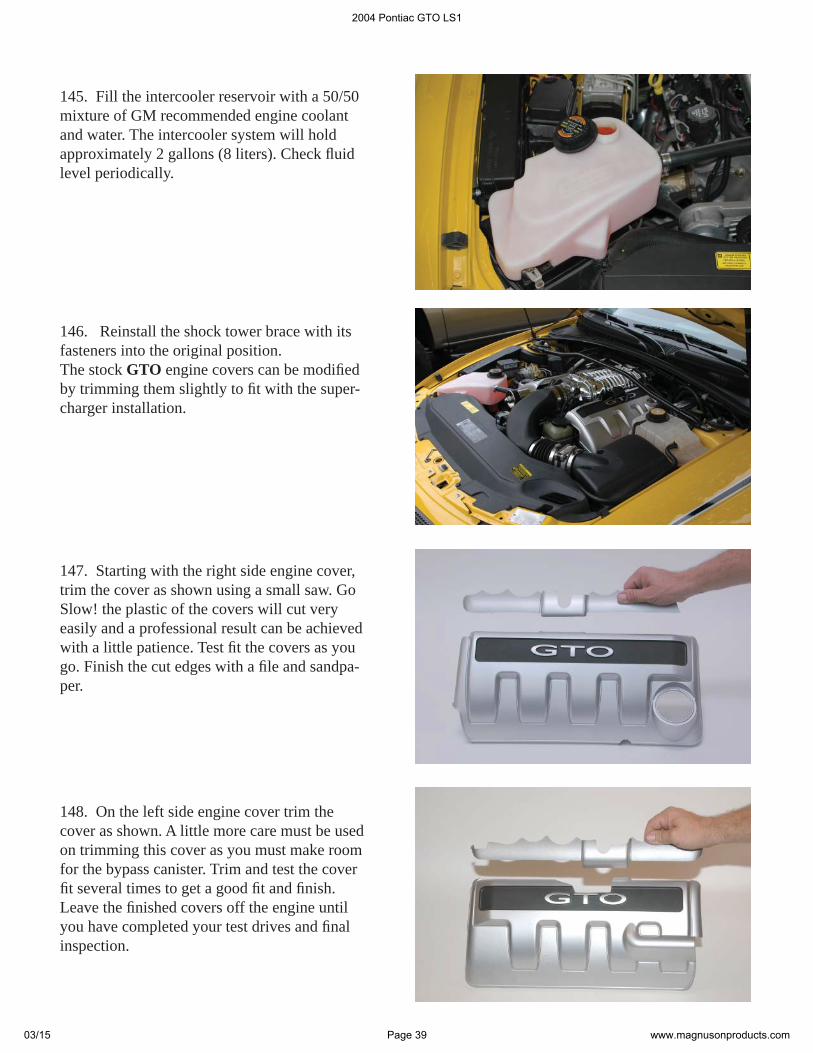
69. At the rear of the supercharger on the pas-senger side, plug in the new MAP and IAT con-nections.
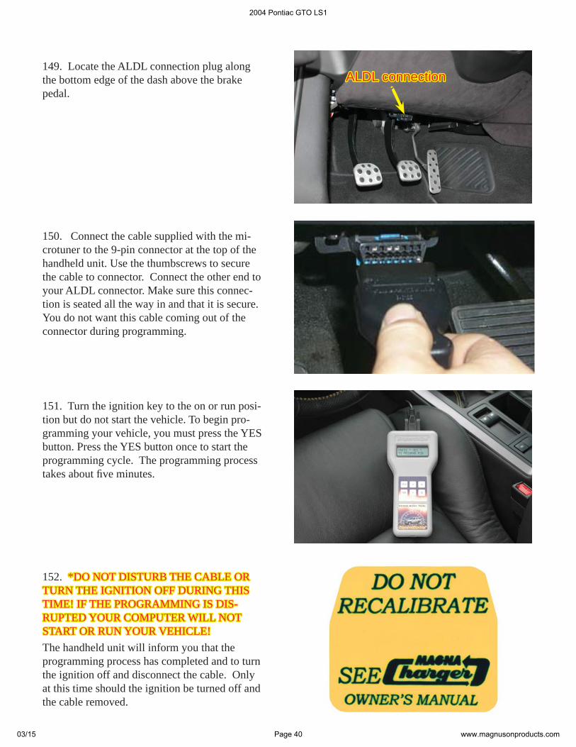
72. Install the IAC and TPS connectors on the throttle body.
2004 Pontiac GTO LS1
03/15 Page 20 www.magnusonproducts.com

76. Lock the cable housing in position by slid-ing the lock clip back into its original closed position.
73. Snap the throttle cable into place on the throttle cable bracket. Next rotate the throttle bellcrank so you can insert the cable end into it’s hole.
75. To adjust the throttle cable housing for cable slack, slide the center lock clip on the housing adjustment outward. Pull or push the housing to achieve the required slack.
74. Check that there is slack in the throttle cable once it is installed. If you cannot depress the cable slightly without moving the bellcrank, loosen the cable housing adjustment as neces-sary.
Move housingMove housingin or out for in or out for slackslack
clip unlockedclip unlocked
clip lockedclip locked
2004 Pontiac GTO LS1
03/15 Page 21 www.magnusonproducts.com
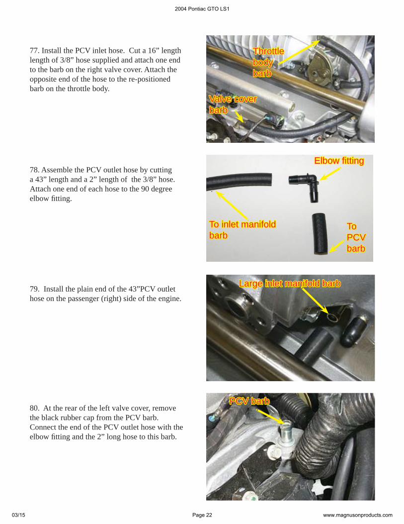
77. Install the PCV inlet hose. Cut a 16” length length of 3/8” hose supplied and attach one end to the barb on the right valve cover. Attach the opposite end of the hose to the re-positioned barb on the throttle body.
79. Install the plain end of the 43”PCV outlet hose on the passenger (right) side of the engine.
Throttle Throttle bodybodybarbbarb
Valve coverValve coverbarbbarb
80. At the rear of the left valve cover, remove the black rubber cap from the PCV barb. Connect the end of the PCV outlet hose with the elbow fi tting and the 2” long hose to this barb.
PCV barbPCV barb
Large inlet manifold barbLarge inlet manifold barb
78. Assemble the PCV outlet hose by cutting a 43” length and a 2” length of the 3/8” hose. Attach one end of each hose to the 90 degree elbow fi tting.
To inlet manifold To inlet manifold barbbarb
To To PCV PCV barbbarb
Elbow fi ttingElbow fi tting
2004 Pontiac GTO LS1
03/15 Page 22 www.magnusonproducts.com
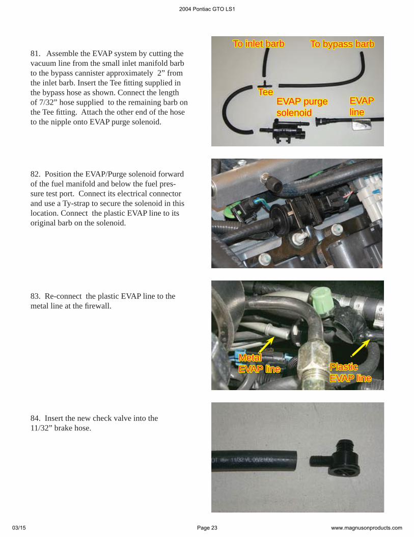
82. Position the EVAP/Purge solenoid forward of the fuel manifold and below the fuel pres-sure test port. Connect its electrical connector and use a Ty-strap to secure the solenoid in this location. Connect the plastic EVAP line to its original barb on the solenoid.
83. Re-connect the plastic EVAP line to the metal line at the fi rewall.
PlasticPlasticEVAP lineEVAP line
MetalMetalEVAP lineEVAP line
84. Insert the new check valve into the 11/32” brake hose.
EVAP EVAP lineline
EVAP purgeEVAP purgesolenoidsolenoid
TeeTee
To inlet barbTo inlet barb To bypass barbTo bypass barb81. Assemble the EVAP system by cutting the vacuum line from the small inlet manifold barb to the bypass cannister approximately 2” from the inlet barb. Insert the Tee fi tting supplied in the bypass hose as shown. Connect the length of 7/32” hose supplied to the remaining barb on the Tee fi tting. Attach the other end of the hose to the nipple onto EVAP purge solenoid.
2004 Pontiac GTO LS1
03/15 Page 23 www.magnusonproducts.com
85. Install the check valve into the grommet on the brake booster.
88. Connect the fuel line to the fi tting on the fuel manifold. Pull fi rmly on the connector to check that it is secure. You should not be able to remove the connector unless you use the removal tool. Replace the stainless steel safety clip that was removed in step 28.
86. On the driver (left) side of the engine con-nect the brake hose to the large barb on the inlet manifold. Route the brake hose along the side of the engine and behind the supercharger to the brake booster.
87. Install the length of 5/32” vacuum hose to the white connector of the accessory vacuum line at the fi rewall. Connect the other end to the manifold barb at the left rear of the supercharger manifold.
ManifoldManifold barb barb
Large inlet manifold Large inlet manifold barbbarb
2004 Pontiac GTO LS1
03/15 Page 24 www.magnusonproducts.com
91. Connect vent line from the coolant reservoir to the lower throttle body barb on the RIGHT side. Secure the hose with the original clamp.
90. Route the other end of the hose to the lower barb on the LEFT side of the throttle body. Se-cure the hose with a #4 clamp supplied.
Coolant vent hoseCoolant vent hose
92. Unclip the small coolant hose from the top of the air box. Unscrew the three cross-head fasteners that secure the airbox cover with a cross head screwdriver and set the cover to one side.
Air boxAir boxfastenersfasteners
89. Install one end of the short length of 1/4” heater hose on the steam vent pipe barb. Secure the hose with a #4 clamp supplied.
Steam vent pipe barbSteam vent pipe barb
2004 Pontiac GTO LS1
03/15 Page 25 www.magnusonproducts.com
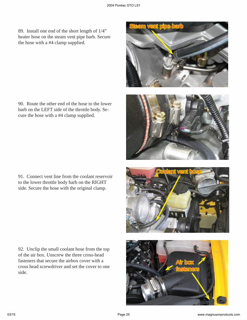
94. Replace the stock fi lter element with the K&N air fi lter element supplied.
93. Remove the stock air fi lter element and discard it.
95. Replace the air box cover, tighten the three fasteners and place the K&N “Warning” label on the cover. Remove the air fl ow meter from the air box cover by loosening its retaining clamp.
Air Flow MeterAir Flow Meter
Retaining Retaining clampclamp
Warning Warning labellabel
96. Remove the four bolts holding the air fl ow meter togather with a Torx T-27 socket and a ratchet. Use great care when seperating the sec-tions of the air fl ow meter, as it is a very delicate instrument.
2004 Pontiac GTO LS1
03/15 Page 26 www.magnusonproducts.com
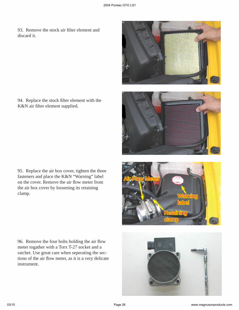
100. Here is the new air tube and mounting components.
99. Reassemble the air fl ow meter sections. Take care not to touch the fi laments and torque the four T-27 Torx bolts to 36 in lbs.Reinstall the air fl ow meter into the air box cover and tighten the retaining clamp securely.
97. Here is the air fl ow meter separated into two sections. DO NOT TOUCH THE FILA-DO NOT TOUCH THE FILA-MENTS ON THE AIR FLOW METER!MENTS ON THE AIR FLOW METER! Touching the fi laments will cause damage and render the air fl ow meter unusable.
98. Remove the mesh from the aluminum air fl ow meter section. Place the section on a hard surface and drive the mesh out from the inside using a small piece of wood or other soft materi-al and a mallet. Drive the mesh downward until you can push it out from the aluminum section.
FilamentsFilaments
MeshMesh
2004 Pontiac GTO LS1
03/15 Page 27 www.magnusonproducts.com
103. Attach the hose end of the air tube to the throttle body. Tighten all clamps securely.
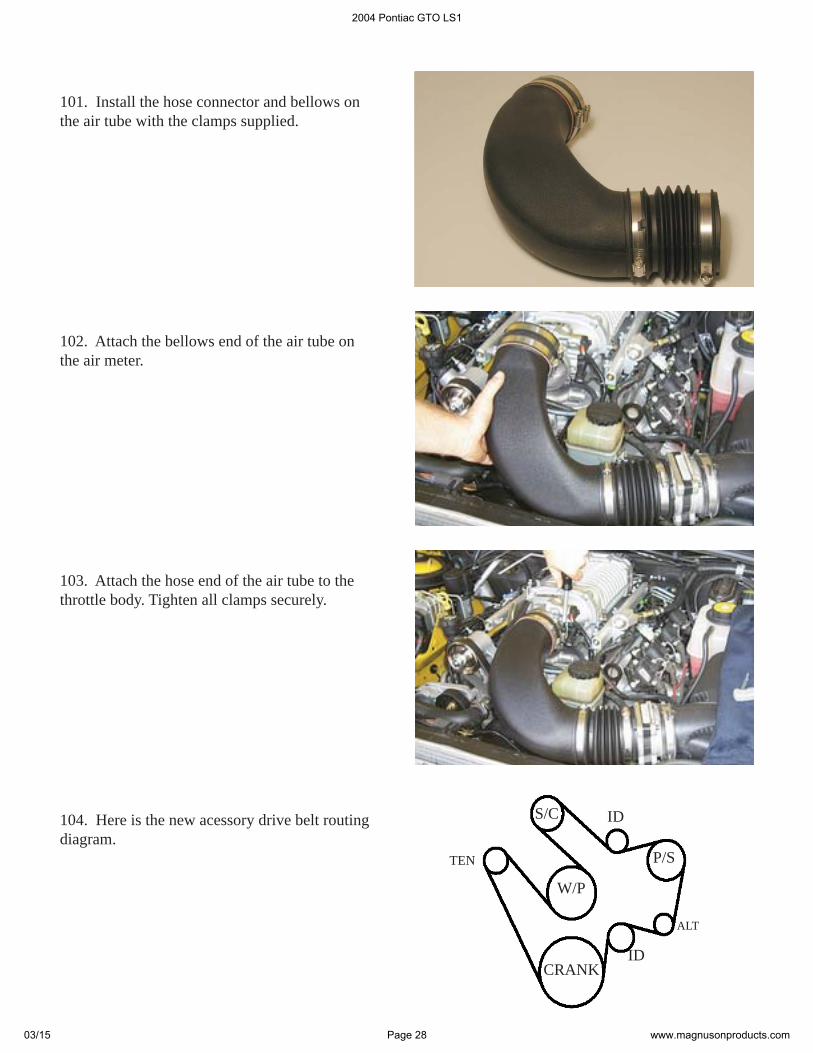
104. Here is the new acessory drive belt routing diagram.
102. Attach the bellows end of the air tube on the air meter.
101. Install the hose connector and bellows on the air tube with the clamps supplied.
S/C
W/P
CRANK
P/STEN
ALT
ID
ID
2004 Pontiac GTO LS1
03/15 Page 28 www.magnusonproducts.com
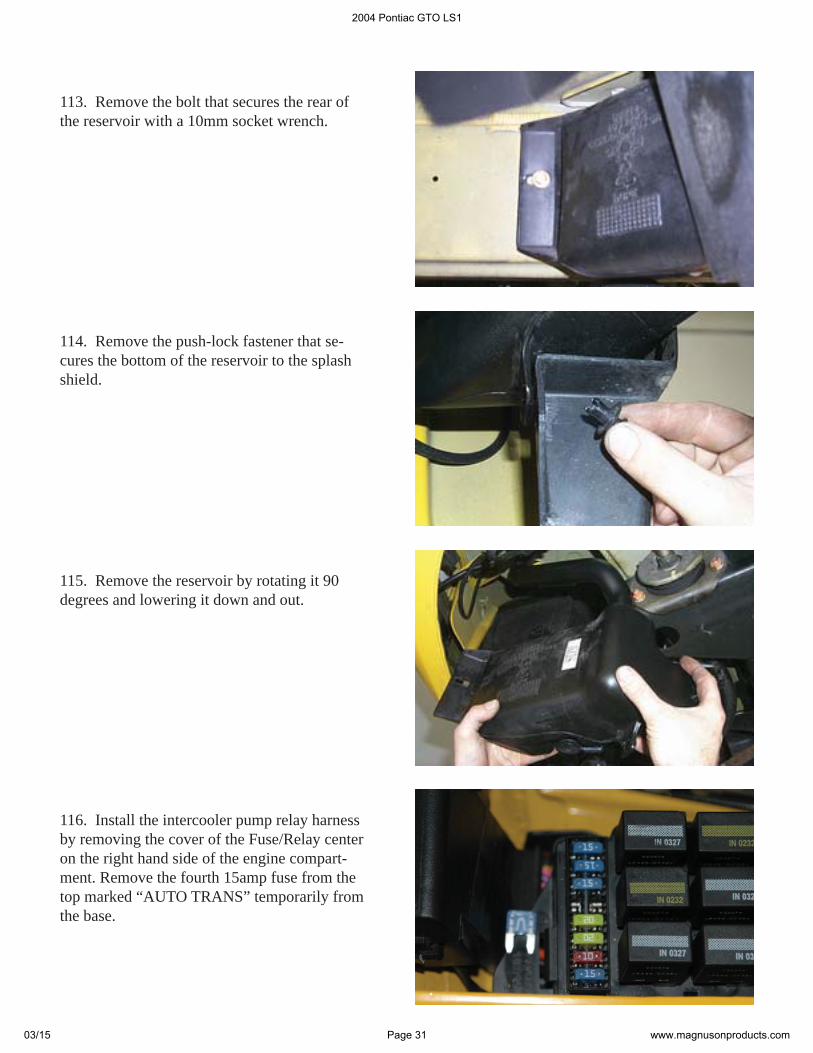
108. Carefully remove the yellow fi ller cap from the neck of the reservoir.
106. Consult the owners manual and raise the vehicle on a automotive hoist or approved jack stands using the factory recomended lift points. Remove the right front wheel.
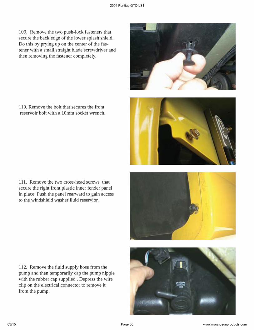
107. This is a diagram of the complete inter-cooler system plumbing. Note the routing of the hoses and their connections.
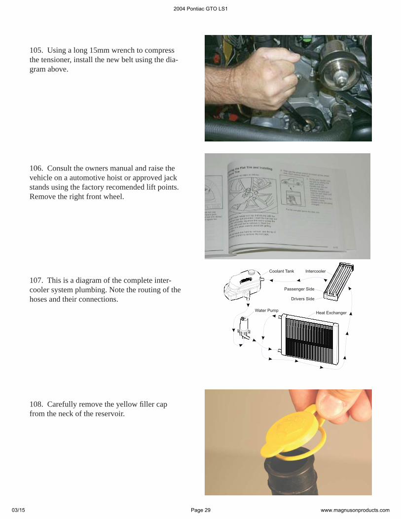
105. Using a long 15mm wrench to compress the tensioner, install the new belt using the dia-gram above.
2004 Pontiac GTO LS1
03/15 Page 29 www.magnusonproducts.com
112. Remove the fl uid supply hose from the pump and then temporarily cap the pump nipple with the rubber cap supplied . Depress the wire clip on the electrical connector to remove it from the pump.
111. Remove the two cross-head screws that secure the right front plastic inner fender panel in place. Push the panel rearward to gain access to the windshield washer fl uid reservior.
110. Remove the bolt that secures the front reservoir bolt with a 10mm socket wrench.
109. Remove the two push-lock fasteners that secure the back edge of the lower splash shield. Do this by prying up on the center of the fas-tener with a small straight blade screwdriver and then removing the fastener completely.
2004 Pontiac GTO LS1
03/15 Page 30 www.magnusonproducts.com
114. Remove the push-lock fastener that se-cures the bottom of the reservoir to the splash shield.
116. Install the intercooler pump relay harness by removing the cover of the Fuse/Relay center on the right hand side of the engine compart-ment. Remove the fourth 15amp fuse from the top marked “AUTO TRANS” temporarily from the base.
115. Remove the reservoir by rotating it 90 degrees and lowering it down and out.
113. Remove the bolt that secures the rear of the reservoir with a 10mm socket wrench.
2004 Pontiac GTO LS1
03/15 Page 31 www.magnusonproducts.com
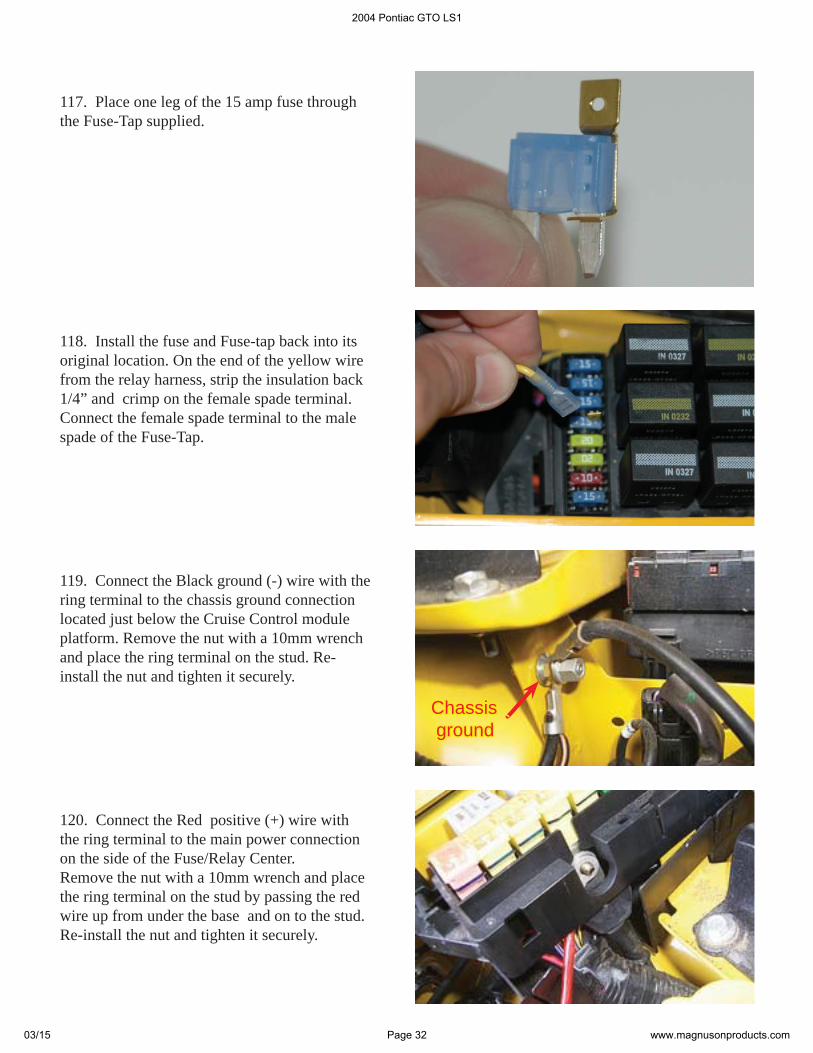
120. Connect the Red positive (+) wire with the ring terminal to the main power connection on the side of the Fuse/Relay Center. Remove the nut with a 10mm wrench and place the ring terminal on the stud by passing the red wire up from under the base and on to the stud. Re-install the nut and tighten it securely.
119. Connect the Black ground (-) wire with the ring terminal to the chassis ground connection located just below the Cruise Control module platform. Remove the nut with a 10mm wrench and place the ring terminal on the stud. Re-install the nut and tighten it securely.
118. Install the fuse and Fuse-tap back into its original location. On the end of the yellow wire from the relay harness, strip the insulation back 1/4” and crimp on the female spade terminal. Connect the female spade terminal to the male spade of the Fuse-Tap.
ChassisChassis ground ground
117. Place one leg of the 15 amp fuse through the Fuse-Tap supplied.
2004 Pontiac GTO LS1
03/15 Page 32 www.magnusonproducts.com
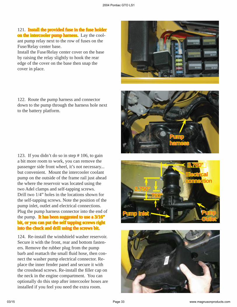
122. Route the pump harness and connector down to the pump through the harness hole next to the battery platform.
Pump Pump harnessharness
123. If you didn’t do so in step # 106, to gain a bit more room to work, you can remove the passenger side front wheel, it’s not necessary...but convenient. Mount the intercooler coolant pump on the outside of the frame rail just ahead the where the reservoir was located using the two Adel clamps and self-tapping screws. Drill two 1/4” holes in the locations shown for the self-tapping screws. Note the position of the pump inlet, outlet and electrical connections. Plug the pump harness connector into the end of the pump. It has been suggested to use a 3/16” It has been suggested to use a 3/16” bit, or you can put the self tapping screws right bit, or you can put the self tapping screws right into the chuck and drill using the screws bit.into the chuck and drill using the screws bit.
2.750”2.750”.750”.750”
3.750”3.750”
PumpPumpOutletOutlet
Pump InletPump Inlet
Electrical Electrical connectionconnection
124. Re-install the windshield washer reservoir. Secure it with the front, rear and bottom fasten-ers. Remove the rubber plug from the pump barb and reattach the small fl uid hose, then con-nect the washer pump electrical connector. Re-place the inner fender panel and secure it with the crosshead screws. Re-install the fi ller cap on the neck in the engine compartment. You can optionally do this step after intercooler hoses are installed if you feel you need the extra room.
121. Install the provided fuse in the fuse holder Install the provided fuse in the fuse holder on the intercooler pump harness.on the intercooler pump harness. Lay the cool-ant pump relay next to the row of fuses on the Fuse/Relay center base.Install the Fuse/Relay center cover on the base by raising the relay slightly to hook the rear edge of the cover on the base then snap the cover in place.
2004 Pontiac GTO LS1
03/15 Page 33 www.magnusonproducts.com
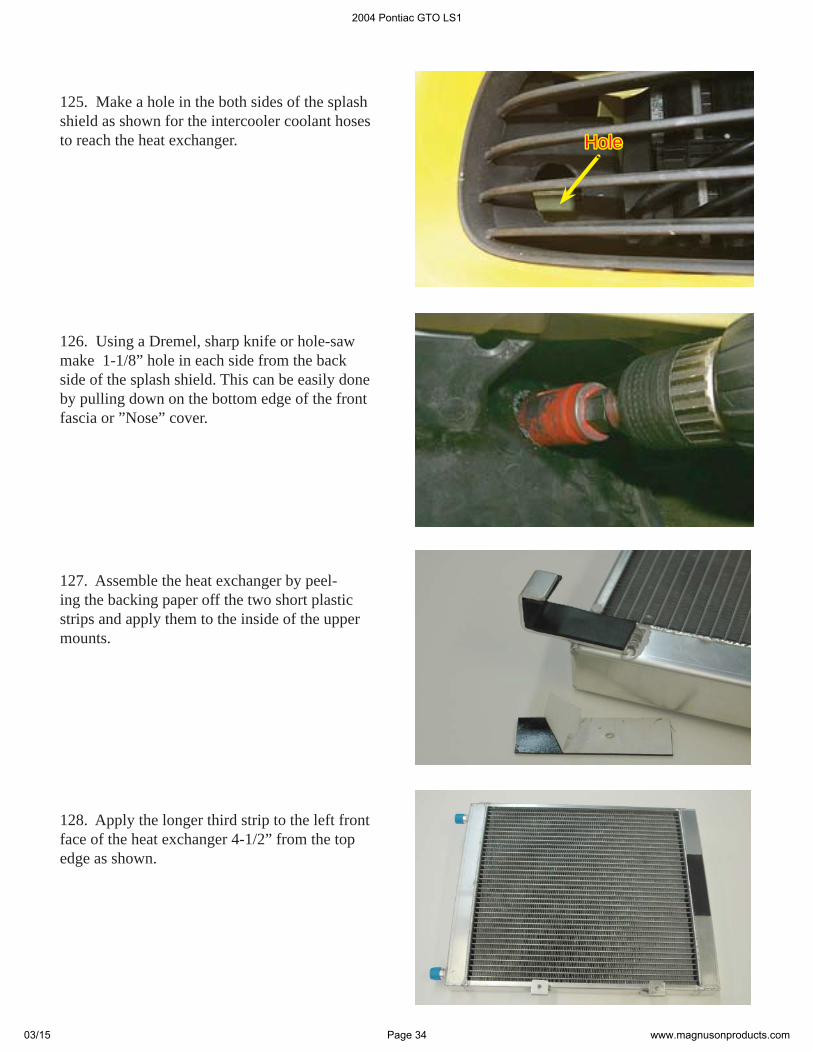
127. Assemble the heat exchanger by peel-ing the backing paper off the two short plastic strips and apply them to the inside of the upper mounts.
128. Apply the longer third strip to the left front face of the heat exchanger 4-1/2” from the top edge as shown.
126. Using a Dremel, sharp knife or hole-saw make 1-1/8” hole in each side from the back side of the splash shield. This can be easily done by pulling down on the bottom edge of the front fascia or ”Nose” cover.
125. Make a hole in the both sides of the splash shield as shown for the intercooler coolant hoses to reach the heat exchanger. HoleHole
2004 Pontiac GTO LS1
03/15 Page 34 www.magnusonproducts.com
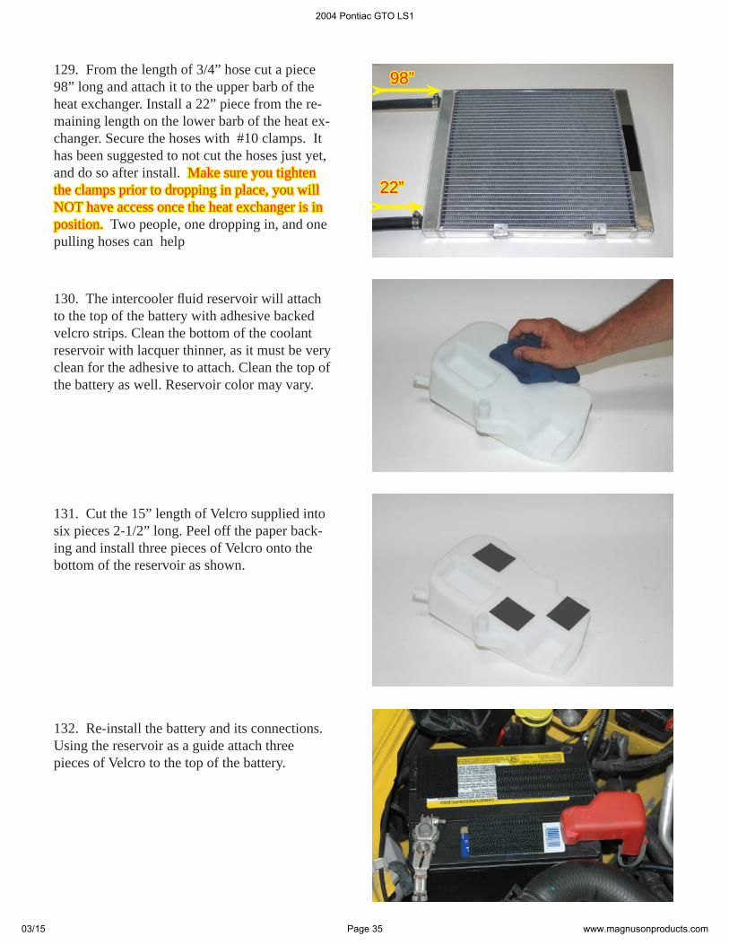
132. Re-install the battery and its connections. Using the reservoir as a guide attach three pieces of Velcro to the top of the battery.
131. Cut the 15” length of Velcro supplied into six pieces 2-1/2” long. Peel off the paper back-ing and install three pieces of Velcro onto the bottom of the reservoir as shown.
130. The intercooler fl uid reservoir will attach to the top of the battery with adhesive backed velcro strips. Clean the bottom of the coolant reservoir with lacquer thinner, as it must be very clean for the adhesive to attach. Clean the top of the battery as well. Reservoir color may vary.
129. From the length of 3/4” hose cut a piece 98” long and attach it to the upper barb of the heat exchanger. Install a 22” piece from the re-maining length on the lower barb of the heat ex-changer. Secure the hoses with #10 clamps. It has been suggested to not cut the hoses just yet, and do so after install. Make sure you tighten Make sure you tighten the clamps prior to dropping in place, you will the clamps prior to dropping in place, you will NOT have access once the heat exchanger is in NOT have access once the heat exchanger is in position.position. Two people, one dropping in, and one pulling hoses can help
22”22”
98”98”
2004 Pontiac GTO LS1
03/15 Page 35 www.magnusonproducts.com

135. Place the intercooler reservoir on the top of the battery. Ensure that the Velcro has a good “grip”.
136. Remove the fi ve push-lock fasteners and the radiator shield.
134. Install the trimmed elbow hose to the lower barb on the reservoir. Secure the hose with a #10 clamp.
133. Trim the supplied molded 90° “elbow” hose supplied by cutting 2” from the short leg and 11” from the long end.
2004 Pontiac GTO LS1
03/15 Page 36 www.magnusonproducts.com
139. Route the elbow hose from the lower barb of the reservoir down to inlet of the cool-ant pump. Connect the hose from the lower heat exchanger barb to the outlet on the pump. Secure both hoses with #10 clamps.
Hose to heat exchangerHose to heat exchanger
Hose from cool-Hose from cool-ant reservoirant reservoir
Washer reservoirWasher reservoir
138. Install the two 6x20mm bolts through the power steering cooler bracket and into the lower brackets on the heat exchanger. You can access these bolts through the lower grill or by pull-ing down the lower splash apron. Tighten the two bolts securely with a 10mm socket wrench. Replace the radiator shield and 5 push-lock fasteners.
140. Route the hose from the upper barb down and across the front of the vehicle. Continue the hose through the new hole in the right side of the splash shield and then up into the engine compartment. Note: The front fascia is removed for clarity only. Use pieces of the supplied Use pieces of the supplied split loom to cover and protect your new hoses split loom to cover and protect your new hoses from chaffi ng against hard edges (I.E. where the from chaffi ng against hard edges (I.E. where the hoses pass through the splash shield).hoses pass through the splash shield).
Hose to water manifoldHose to water manifold
137. Lower the front heat exchanger into place on the front of the A/C condenser. As you lower the heat exchanger and hoses into place, pull the black A/C dryer cylinder forward on the left side to allow the heat exchanger to pass and the upper brackets to sit fl at on the top of the A/C condenser.
SPLIT-LOOMSPLIT-LOOM
2004 Pontiac GTO LS1
03/15 Page 37 www.magnusonproducts.com
143. Replace the lower splash shield with the two push-lock fasteners that secure it.
142. Using the remaining hose, cut this piece at 13” long and install it onto the right barb on the intercooler water manifold. Connect the other end to the upper barb on the intercooler reser-voir. Secure the hose with #10 clamps.
144. Re-install the right front wheel and torque the lug nuts to 85ft-lbs. (115 N-m)
141. Install the hose to the left barb on the intercooler water manifold. Secure the hose with a #10 clamp.
2004 Pontiac GTO LS1
03/15 Page 38 www.magnusonproducts.com
146. Reinstall the shock tower brace with its fasteners into the original position.The stock GTO engine covers can be modifi ed by trimming them slightly to fi t with the super-charger installation.
148. On the left side engine cover trim the cover as shown. A little more care must be used on trimming this cover as you must make room for the bypass canister. Trim and test the cover fi t several times to get a good fi t and fi nish.Leave the fi nished covers off the engine until you have completed your test drives and fi nal inspection.
147. Starting with the right side engine cover, trim the cover as shown using a small saw. Go Slow! the plastic of the covers will cut very easily and a professional result can be achieved with a little patience. Test fi t the covers as you go. Finish the cut edges with a fi le and sandpa-per.
145. Fill the intercooler reservoir with a 50/50 mixture of GM recommended engine coolant and water. The intercooler system will hold approximately 2 gallons (8 liters). Check fl uid level periodically.
2004 Pontiac GTO LS1
03/15 Page 39 www.magnusonproducts.com
The handheld unit will inform you that the programming process has completed and to turn the ignition off and disconnect the cable. Only at this time should the ignition be turned off and the cable removed.
152. *DO NOT DISTURB THE CABLE OR *DO NOT DISTURB THE CABLE OR TURN THE IGNITION OFF DURING THIS TURN THE IGNITION OFF DURING THIS TIME! IF THE PROGRAMMING IS DIS-TIME! IF THE PROGRAMMING IS DIS-RUPTED YOUR COMPUTER WILL NOT RUPTED YOUR COMPUTER WILL NOT START OR RUN YOUR VEHICLE!START OR RUN YOUR VEHICLE!
150. Connect the cable supplied with the mi-crotuner to the 9-pin connector at the top of the handheld unit. Use the thumbscrews to secure the cable to connector. Connect the other end to your ALDL connector. Make sure this connec-tion is seated all the way in and that it is secure. You do not want this cable coming out of the connector during programming.
151. Turn the ignition key to the on or run posi-tion but do not start the vehicle. To begin pro-gramming your vehicle, you must press the YES button. Press the YES button once to start the programming cycle. The programming process takes about fi ve minutes.
149. Locate the ALDL connection plug along the bottom edge of the dash above the brake pedal.
ALDL connectionALDL connection
2004 Pontiac GTO LS1
03/15 Page 40 www.magnusonproducts.com
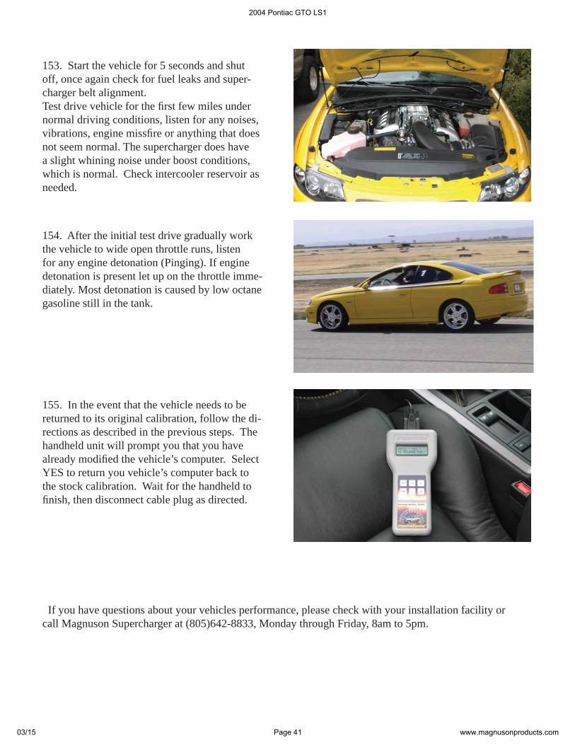
154. After the initial test drive gradually work the vehicle to wide open throttle runs, listen for any engine detonation (Pinging). If engine detonation is present let up on the throttle imme-diately. Most detonation is caused by low octane gasoline still in the tank.
155. In the event that the vehicle needs to be returned to its original calibration, follow the di-rections as described in the previous steps. The handheld unit will prompt you that you have already modifi ed the vehicle’s computer. Select YES to return you vehicle’s computer back to the stock calibration. Wait for the handheld to fi nish, then disconnect cable plug as directed.
If you have questions about your vehicles performance, please check with your installation facility or call Magnuson Supercharger at (805)642-8833, Monday through Friday, 8am to 5pm.
153. Start the vehicle for 5 seconds and shut off, once again check for fuel leaks and super-charger belt alignment.Test drive vehicle for the fi rst few miles under normal driving conditions, listen for any noises, vibrations, engine missfi re or anything that does not seem normal. The supercharger does have a slight whining noise under boost conditions, which is normal. Check intercooler reservoir as needed.
2004 Pontiac GTO LS1
03/15 Page 41 www.magnusonproducts.com

Ventura, CA. Magna Charger, manufacturer of superchargers and supercharger systems for foreign and domestic vehicles, was presented the prestigious award at the annual Specialty Equipment Market Association Show (SEMA) in Las Vegas, Nevada.
Sponsored by General Motors Corporation, the SEMA Design Award for the “Most Innovative Prod-uct” was awarded to Magna Charger and recognized by the all-star team of judges for their outstand-ing and innovative design achievement. The criteria used by the judges included innovation, techni-cal achievement, quality and workmanship.
The award was presented for the Radix® Intercooled supercharger system, designed for the Chevro-let, GMC and Cadillac, 4.8L, 5.3L and 6.0L General Motors Trucks and SUV’s including the new H2 and SSR.
Please enjoy your “Magna Charged” performance responsibly!
Special thanks to LS1GTO.com forum member “Steel Chicken” for instruction manual edit suggestions.Special thanks to LS1GTO.com forum member “Steel Chicken” for instruction manual edit suggestions.
2004 Pontiac GTO LS1
03/15 Page 42 www.magnusonproducts.com